

Page 1
Palm Size Digital Multimeter
Model: 72-7765A / 72-10420A / 72-7770A
1
Page 2
IMPORTANT SAFETY INFORMATION
Please read these instructions carefully before use and retain for future
reference.
• Check the test leads, probes and case insulation before using. If you nd any
breakage or abnormality, or you consider the device is broken, stop using the
device immediately.
• When using the test probes, keep your ngers behind the nger protection ring.
• Do not use the meter with the back cover open.
• Select the appropriate test range for measurements.
• Ensure all inputs are less than the range selected otherwise it may cause electrical
shock or meter damage.
• Do not change the range selector position during measurements.
• Do not apply a voltage over 250V between COM terminal and ground.
• Take caution when working voltages are above 60V DC or 30V AC rms.
• Do not connect the meter to voltage signals when the range selector is on current,
resistance, diode or continuity range.
• When measuring current, each single measurement should be shorter than 10
seconds. For current values over 5A, the wait period between each measurement
must be longer than 15 minutes.
• When a measurement has been completed, disconnect the testing probes from
the circuit under test.
• Replace the batteries as soon as the low battery indicator appears on the display.
• Remove dead batteries from the meter or if it is not going to be used for a long
time.
• Never mix old and new batteries together, or different types of batteries.
• Never dispose of batteries in a re, or attempt to recharge ordinary batteries.
• Before replacing the battery, turn off the meter and disconnect all the test probes.
• To prolong battery life turn off the meter after use.
WHAT’S INCLUDED
• Digital palm size Multimeter.
• Instruction manual.
• Test leads.
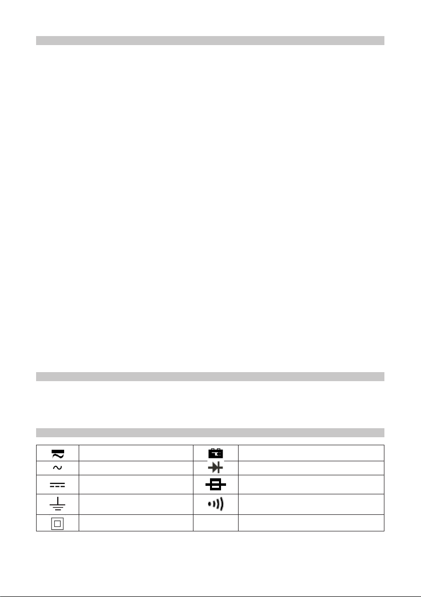
ELECTRICAL SYMBOLS
AC or DC Low battery
AC Diode
DC Fuse
Ground Continuity sounder
Double insulation
2
Page 3
FUNCTIONS
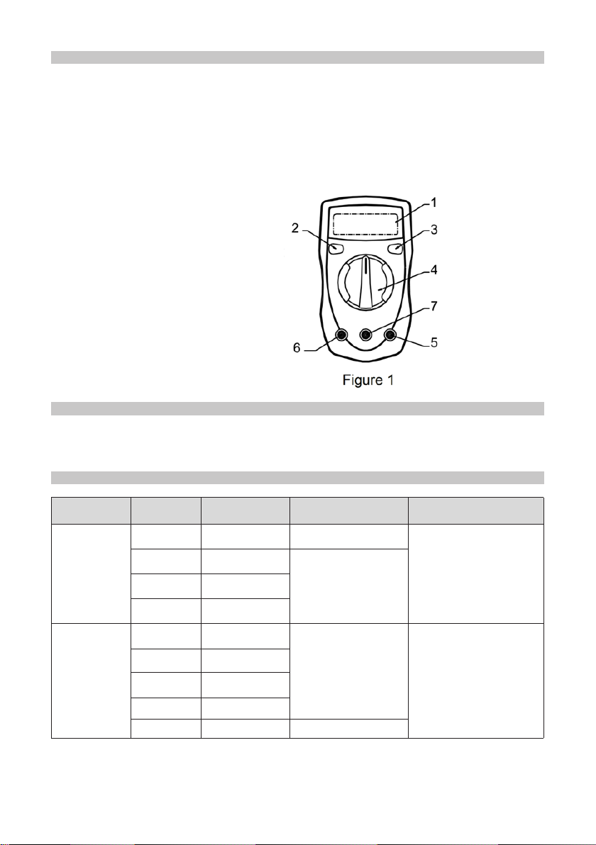
Meter front panel (Figure 1)
1. LCD display
2. SELECT button(72-7765A)(Press the yellow button to switch between AC and
DC current, or between continuity and diode measurements, indicated by buzzer.
In standby mode, press it to activate the meter and cancel auto power off
function.) Or HOLD button (72-10420A/72-7770A) (Press the yellow button,
then the current displayed data will be held with letter H shown on LCD. Press it
again to exit data hold operation.
3. Backlight display button
4. Range selector
5. COM input terminal
6. 10A input terminal
7. Other input terminal
OPERATING PARAMETERS
• Operating temperature: 23ºC ± 5ºC.
• Relative humidity: <75%.
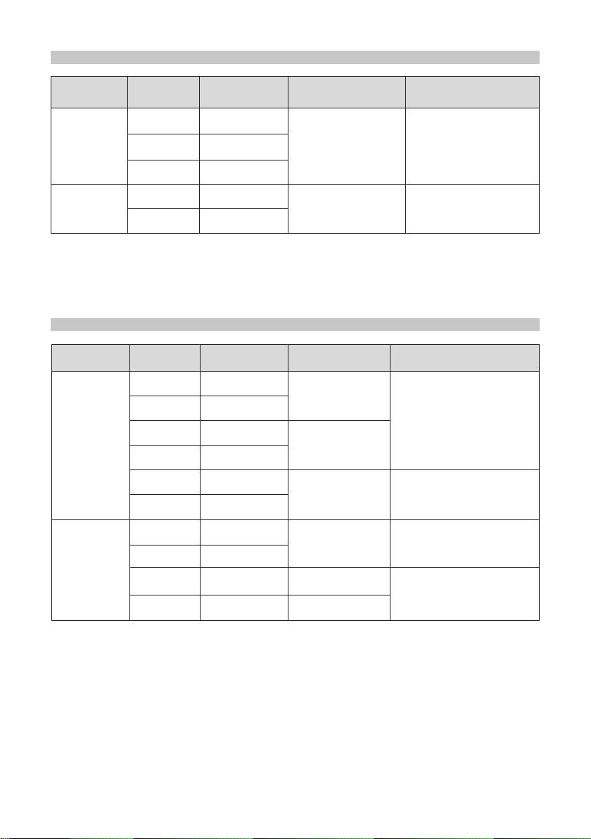
DC VOLTAGE
Model Range Resolution Accuracy Overload Protection
400mV 0.1mV ± (0.8%+3)
4V 1mV
72-7765A
40V 10mV
± (0.8%+1)
250V AC
250V 100mV
200mV 100μV
72-10420A
72-7770A
2000mV 1mV
20V 10mV
± (0.5%+2)
250V DC and AC
200V 100mV
250V 1V ± (0.8%+2)
Note:
• Input impedance is 10MΩ.
3
Page 4
AC VOLTAGE
Model Range Resolution Accuracy Overload Protection
4V 1mV
72-7765A
40V 10mV
± (1.2%+3) 250VAC
250V 100mV
72-10420A
72-7770A
200V 100mV
± (1.2%+10) 250V DC and AC
250V 1V
Notes:
• Input impedance: ~ 5MΩ.
• Displaying effective value of sine wave (mean value response).
• Frequency response: 40 ~ 400Hz.
DC CURRENT
Model Range Resolution Accuracy Overload Protection
400μA 0.1μA
± (1%+2)
72-7765A
4000μA 1μA
40mA 10μA
± (1.2%+2)
400mA/250V fast type
fuse Φ5x20mm
400mA 100μA
72-10420A
72-7770A
4A 1mA
± (1.5%+5)
10A 10mA
2000μA 0.1μA
± (0.5%+2)
20mA 1μA
200mA 100μA ± (1.2%+2)
10A 10mA ± (2%+5)
10A/600V fast type fuse
Φ6x25mm
200mA, 250V fast type
fuse Φ5x20mm
10A, 600V fast type
fuse Φ6x25mm
Note:
• At 10A range: every measurement should be <10s, the interval between
measurements must be > 15 minutes.
4
Page 5

AC CURRENT
Range Resolution Accuracy Overload protection
400μA 0.1μA
± (1.5%+5)
4000μA 1μA
40mA 10μA
400mA/250V fast type fuse
Φ5x20mm
± (2%+5)
400mA 100μA
4A 1mA
± (2.5%+5) 10A/600V fast type fuse Φ6x25mm
10A 10mA
DIODE AND CONTINUITY MEASUREMENT
Range Resolution Accuracy Overload protection
1mV
0.1Ω
(72-7765A)
Displaying approximate
forward voltage drop
Beeping if impedance <100Ω
250V DC and AC
1Ω Beeping if resistance <70Ω
RESISTANCE
Model Range Resolution Accuracy
Overload
protection
400Ω 0.1Ω ± (1.2%+2)
4kΩ 1Ω ± (1%+2)
40kΩ 10Ω ± (1%+2)
72-7765A
400kΩ 100Ω ± (1%+2)
4MΩ 1kΩ ± (1.2%+2)
40MΩ 10kΩ ± (1.5%+5)
200Ω 0.1Ω ± (0.8%+5)
250V DC and AC
2000Ω 1Ω ± (0.8%+2)
72-10420A
72-7770A
20kΩ 10Ω ± (0.8%+2)
200kΩ 100Ω ± (0.8%+2)
20MΩ 10kΩ ± (1%+5)
200MΩ 100kΩ
± (5%[reading-10]+10)
(72-7770A)
5
Page 6

TEMPERATURE (Model 72-10420A only
Range Resolution Accuracy Overload protection
-40 ~ 150°C
1℃
150 ~ 1000°C ± (1.5%+15)
SQUARE WAVE OUTPUT (Model 72-7770A only
Range Function
OUT
OPERATION
Voltage measurement (See Figure 1&2)
DC voltage measurement
For Model 72-7765A, the testing ranges are: 400mV, 4V, 40V and 250V.
For Model 72-10420A and 72-7770A, the testing ranges are: 200mV, 2000mV, 20V,
200V and 250V.
To measure DC voltage, perform the following steps:
• Insert the red test probe into the VΩmA terminal and the black test probe into the
COM terminal.
• Turn the range selector to V range(s).
• Connect the test probes with the circuit being measured. The measured value will
be shown on LCD.
± (1%+3)
250V DC and AC
~ 50Hz square wave
AC voltage measurement
For Model 72-7765A, the ranges are: 4V, 40V and 250V
For Model 72-10420A and 72-7770A, the ranges are: 200V and 250V.
6
Page 7

To measure AC Voltage, perform the following steps:
• Insert the red test probe into the VΩmA terminal and the black test probe into the
COM terminal.
• Turn the range selector to V
• Connect the test probes to the circuit being measured. The measured value will be
shown on LCD, which is the effective value of sine wave (mean value response).
Notes:
• DCV and ACV measurement with 72-7765A is auto range.
• If the voltage to be measured is unknown, use the maximum measuring range
(250V) and reduce the range step by step until a satisfactory reading is obtained.
(Do not adjust when connected to the circuit).
• If LCD shows “OL”, this indicates the measured value is higher than the selected
range. Select a higher range in order to obtain a measured value.
• In each range, the meter has an input impedance of about 10MΩ. This loading
effect can cause measurement errors in high impedance circuits.
• If the circuit impedance is less than or equal to 10kΩ, the error is negligible (0.1%
or less).
Current measurement (See Figure 3 & 4)
WARNING
• Never attempt a current measurement where the voltage between either terminal
and ground is greater than 60V.
DC current measurement
• Model 72-7765A testing range: 400μA, 4000μA, 40mA, 400mA, 4A and 10A
• Model 72-7770A/72-10420A testing range: 2000μA, 20mA, 200mA and 10A
To measure DC current, perform the following steps:
• Turn off the power and discharge all high-voltage capacitors of the circuit to be
measured.
• Insert the red test probe into the VΩmA or 10A terminal and the black test probe
into the COM terminal.
• Turn the range selector to
• Connect the red test probe to the positive electrode and the black test probe to the
negative electrode of the circuit in series.
• Turn on the circuit power. The measured value shows on the display.
7
Page 8

AC current measurement (Model 72-7765A only)
• The testing ranges are: 400μA, 4000μA, 40mA, 400mA, 4A and 10A
• To measure AC current, perform the following steps:
• Turn off the power and discharge all high-voltage capacitors of the circuit to be
measured.
• Insert the red test probe into the VΩmA or 10A terminal and the black test probe
into the COM terminal.
• Turn the range selector to μA/mA/A range.
• Press the SELECT button for switching DC measurement to AC measurement.
• Connect the red test probe to the positive electrode and the black test probe to the
negative electrode of the circuit in series.
• Turn on the circuit power. The measured value shows on the display.
Notes:
• If the current to be measured is unknown, use the maximum measurement range
(10A) and reduce the range step by step until a satisfactory reading is obtained.
(Do not adjust when connected to the circuit).
• When current measurement has been completed, disconnect the testing probes
from the circuit under test.
Resistance measurement (See Figure 5)
WARNING: To avoid damages to the meter or to the devices under test, disconnect
circuit power and discharge all the high-voltage capacitors before measuring resistance.
Model 72-7765A testing ranges: 400Ω, 4kΩ, 40kΩ, 400kΩ, 4MΩ and 40MΩ
Model 72-10420A testing ranges: 200Ω, 2000Ω, 20kΩ, 200kΩ and 20MΩ
Model 72-7770A testing ranges: 200Ω, 2000Ω, 20kΩ, 200kΩ, 20MΩand 200MΩ
To measure resistance, perform the following steps:
• Insert the red test probe into the VΩmA terminal and
the black test probe into the COM terminal.
• Turn the range selector to Ω range(s).
• Connect the test probes to the circuit in parallel.
• Read the testing result on the display.
Notes:
• The test probes can add 0.1Ω to 0.3Ω of error to
resistance measurement. To obtain precise reading
in low-resistance measurement, short-circuit the test
probes beforehand and record the reading obtained.
Subtract this value from the measured value to obtain the resistance of the circuit
under test.
• For high resistance measurement (>1MΩ), it normally takes several seconds to
obtain a stable reading.
8
Page 9

Diode and continuity measurement (See Figure 6&7)
Diode measurement
Perform diode test to check diodes, transistors, and other semiconductor devices.
The meter can measure the voltage drop of PN joint of diode and other semiconductors in
this range. For a silicon semiconductor with normal structure, the reading of the forward
voltage drop should be within 0.5~0.8V.
To test diode, perform the following steps:
• Insert the red test probe into the VΩmA terminal and the black test probe into the
COM terminal.
• Turn the range selector to range.
• For forward voltage drop readings on any semiconductor components, connect
the red test probe to the anode and the black test probe to the cathode of the
components.
• The measured value will be shown on the display. This is the voltage drop across
the diode. If the display shows “OL”, it indicates the open circuit or reversed
connection.
9
Page 10

Continuity measurement
To test continuity, perform the following steps:
• Insert the red test probe into the VΩmA terminal and the black test probe into the
COM terminal.
• Turn the range selector to range.
• Connect the test probes to the circuit to be measured. The buzzer beeps if the
circuit resistance is less than 100Ω. If the display shows “OL”, this indicates the
open circuit.
Temperature measurement (Model 72-10420A only, see gure 8)
The temperature measurement range is -40°C - 1000°C.
To measure temperature, perform the following steps:
• Insert the output ports (anode and cathode) of the temperature probe respectively
into VΩmA°C /°F and COM terminals.
• Turn the range selector to °C / °F range.
• Place the temperature measuring end of the
temperature probe on the surface of or in the
object to be measured. The measured value will be
shown on the display.
Notes:
• The inside meter temperature will be automatically
displayed when there is no temperature probe
connected.
• The point contact temperature probe attached
to the meter can only measure temperature
lower than 250°C. When higher temperature
measurement is needed, please use other suitable temperature probe.
Square wave output (Model 72-7770A only)
To avoid meter damage, do not connect the output terminal (red test probe) to the
circuit with voltage higher than 10V.
To measure square wave output, perform the following steps:
• Turn the range selector to OUT range.
• The meter outputs square wave signal between VΩmA and COM Terminals.
Notes:
• The frequency is about 50Hz.
• The output amplitude is >2.3Vpp when the meter is connected to the circuit with
1MΩ resistance.
• When measurement is completed, disconnect the test probes from the circuit under
test.
10
Page 11

GENERAL SPECIFICATIONS
Item Model
72-7765A 72-10420A/72-7770A
Max voltage (including
transient overvoltage) between
250V rms
terminals and ground
VΩmA terminal fuse protection
400mA, 250V fast type,
Φ5x20mm
200mA, 250V fast
type, Φ5x20mm
10A terminal fuse protection 10A, 600V fast type, Φ6x25mm
Range selection auto manual
Max display 3999 1999
Battery 1.5V(AAA)x2
9V Battery NEDA1604
or 6F22 or 006Px1
Operating temperature 0 ~ 40°C
Storage temperature -10 to 50°C
Relative humidity 0 to 30°C: 75%, 31 to 40°C: <50%
Dimension (H x W x L) 130 x 73.5 x 35mm
Weight (including battery) 156g
BATTERY AND FUSE REPLACEMENT
Replacing the battery:
• Remove the test probes from the meter input terminals and turn the range selector
to OFF position.
• Unscrew and lift off the back cover.
• Remove the old battery.
• Replace with the new battery of same type.
• Ret the back cover.
Replacing the fuse:
• Remove the test probes from the meter input terminals and turn the range selector
to OFF position.
• Unscrew and lift off the back cover and remove the fuse from its holder.
• Replace ONLY with the fuses that match the following specications:
400mA, 250V fast type, Φ5x20mm (72-7765A).
200mA, 250V fast type, Φ5x20mm (72-10420A/72-7770A).
10A, 600V fast type, Φ6x25mm.
• Ret the back cover.
11
Page 12

INFORMATION ON WASTE DISPOSAL FOR CONSUMERS OF
ELECTRICAL & ELECTRONIC EQUIPMENT
These symbols indicate that separate collection of Waste Electrical and Electronic Equipment
(WEEE) or waste batteries is required. Do not dispose of these items with general household
waste. Separate for the treatment, recovery and recycling of the materials used. Waste batteries
can be returned to any waste battery recycling point which are provided by most battery retailers.
Contact your local authority for details of the battery and WEEE recycling schemes available in
your area.
Made in China. PR2 9PP
12
Man Rev 1.0
 Loading...