

Page 1

Model 72-7720/72-7725: OPERATING MANUAL
Table of Contents
Title
Overview
Unpacking Inspection
Safety Information
Rules For Safe Operation
International Electrical Symbols
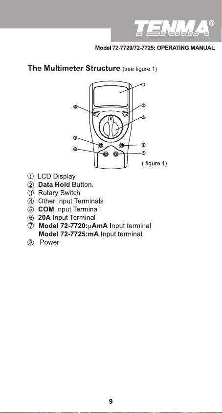
The Multimeter Structure
Functional Buttons
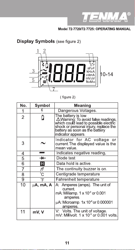
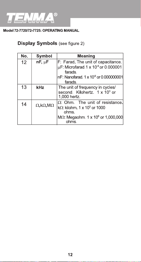
Display Symbols
Measurement Operation
A. DC Voltage Measurement
B. AC Voltage Measurement
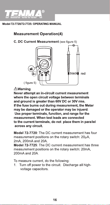
C. DC Current Measurement
D. AC Current Measurement
E. Measuring Resistance
F. Model 72-7725:
Frequency Measurement
G. Model 72-7725:
Temperature Measurement
H. Capacitance Measurement
I. Measuring Diodes & Continuity
Testing for Continuity
Sleep Mode
Turning on the Auto Display Backlight
General Specifications
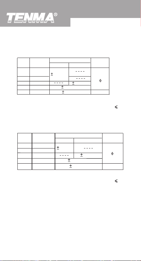
Accuracy Specifications
A. DC Voltage
B. AC Voltage
C. DC Current
D. AC Current
Page
3
4
5
6
8
9
10
11
13
13
14
16
17
19
20
21
22
23
24
25
25
26
27
27
27
28
28
1
Page 2

Model 72-7720/72-7725: OPERATING MANUAL
Title
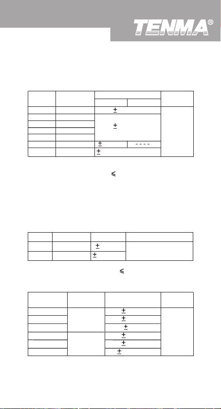
E. Resistance Test
F. Model 72-7725: Frequency
G. Model 72-7725:
Temperature
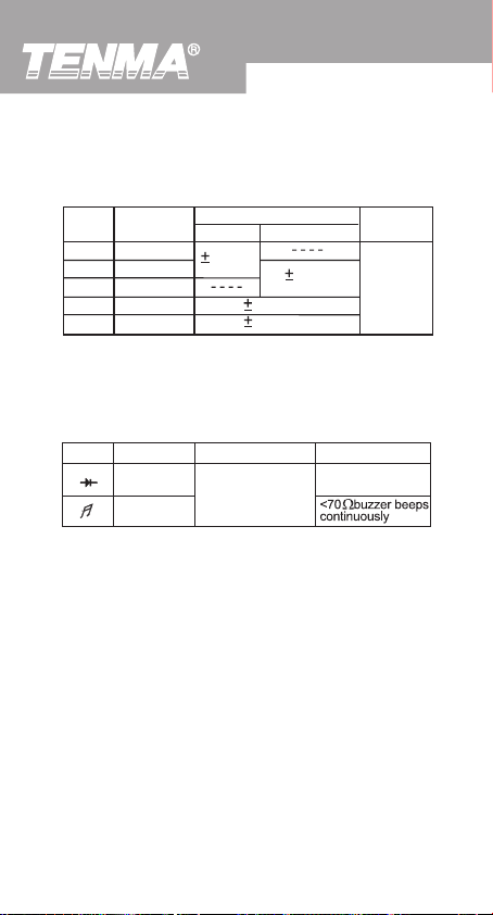
H. Capacitance
I. Diodes and Continuity Test
Maintenance
A. General Service
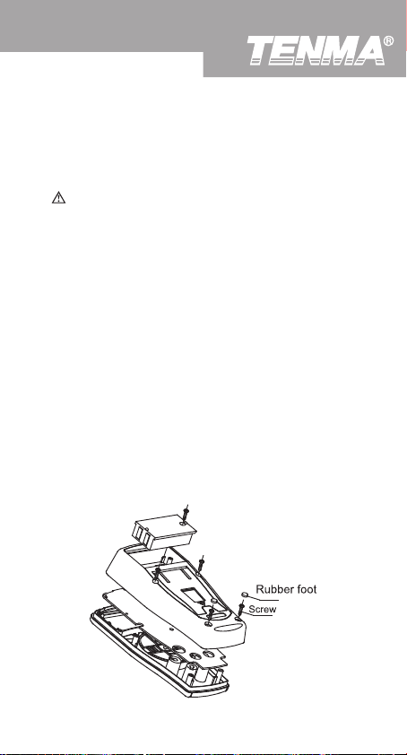
B. Replacing the Battery
C. Replacing the Fuses
Page
29
29
29
30
30
31
32
32
32
2
Page 3

Model 72-7720/72-7725: OPERATING MANUAL
Overview
Warning
To avoid electric shock or personal injury, read the
"Safety Information" and "Rules for Safe Operation"
carefully before using the Meter.
Digital Multimeters Model 72-720 and 72-7725 (hereafter
referred to as “the Meter”) are 3 1/2 digits with steady
operations, fashionable structure and highly reliable
hand-held measuring instrument. The Meter uses large
scale of integrated circuit with double integrated A/D
converter as its core and has full range overload
protection. The Meter not only can measure AC/DC
Voltage, AC/DC Current, Resistance, Capacitance,
T emperature, Frequency, Diodes and Continuity , but also
has Data Hold, Full Icon Display and Sleep Mode features.
The Meter adopted advanced “co-injection” technique in
order to provide sufficient insulation and anti-shaking.
In addition, the Automatic Display Backlight feature
enables user to work in a dim condition.
3
Page 4

Model 72-7720/72-7725: OPERATING MANUAL
Unpacking Inspection
Open the package case and take out the Meter. Check
the following items carefully for missing or damaged
parts:
Item
Description
1
English Operating Manual
2
Test Lead
3
Test Clip
Point Contact Temperature Probe
4
(72-7725 only)
In the event you find items missing or damaged, please
contact your dealer immediately.
Qty
1 piece
1 pair
1 pair
1 piece
4
Page 5

Model 72-7720/72-7725: OPERATING MANUAL
Safety Information
This Meter complies with the standards IEC61010: in
pollution degree 2, overvoltage category (CAT. II 1000V,
CAT. III 600V) and double insulation.
CAT. II: Local level, appliance, PORTABLE EQUIPMENT
etc., with smaller transient voltage overvoltages than
CAT. III
CAT. III: Distribution level, fixed installation, with smaller
transient overvoltages than CAT. IV
Use the Meter only as specified in this operating manual,
otherwise the protection provided by the Meter may be
impaired.
In this manual, a Warning identifies conditions and
actions that pose hazards to the user, or may damage
the Meter or the equipment under test.
A Note identifies the information that user should pay
attention to.
International electrical symbols used on the Meter and
in this Operating Manual are explained on page 8.
5
Page 6

Model 72-7720/72-7725: OPERATING MANUAL
Rules For Safe Operation (1)
Warning
To avoid possible electric shock or personal injury,
and to avoid possible damage to the Meter or to the
equipment under test, adhere to the following rules:
l Before using the Meter inspect the case. Do
not use the Meter if it is damaged or the case
(or part of the case) is removed. Look for cracks
or missing plastic. Pay attention to the insulation
around the connectors.
l Inspect the test leads for damaged insulation
or exposed metal. Check the test leads for
continuity. Replace damaged test leads with
identical model number or electrical specifications
before using the Meter.
l Do not apply more than the rated voltage, as
marked on the Meter, between the terminals or
between any terminal and ground.
l The rotary switch should be placed in the correct
position and no changeover of range shall be
made during measurement, to prevent damage
of the Meter.
l When working at an effective voltage over 60V
DC or 30V rms AC, special care should be taken
for there is danger of electric shock.
l Use the proper terminals, function, and range
for your measurements.
l Do not use or store the Meter in an environment
of high temperature, humidity, explosive,
flammable and strong magnetic field. The
performance of the Meter may deteriorate after
dampened.
l When using the test leads, keep your fingers
behind the finger guards.
6
Page 7

Model 72-7720/72-7725: OPERATING MANUAL
Rules For Safe Operation (2)
l Disconnect circuit power and discharge all high voltage capacitors before testing resistance,
continuity, diodes, capacitance or current.
l Before measuring current, check the Meter’s
fuses and turn off power to the circuit before
connecting the Meter .
l Replace the battery as soon as the battery
indicator appears. With a low battery, the Meter
might produce false readings that can lead to
electric shock and personal injury.
l Remove test leads, test clips and temperature
probe from the Meter and turn the Meter power
off before opening the Meter case.
l When servicing the Meter, use only the same
model number or identical electrical specifications
replacement parts.
l The internal circuit of the Meter shall not be
altered at will to avoid damage of the Meter and
any accident.
l Soft cloth and mild detergent should be used
to clean the surface of the Meter when servicing.
No abrasive and solvent should be used to
prevent the surface of the Meter from corrosion,
damage and accident.
l The Meter is suitable only for indoor use.
l Turn the Meter power off when it is not in use
and take out the battery when not using for a
long time.
l Periodically check the battery as it may leak
after some time.If leakage is apparent,the battery
should be immediately replaced to prevent
damage.
7
Page 8
Model 72-7720/72-7725: OPERATING MANUAL
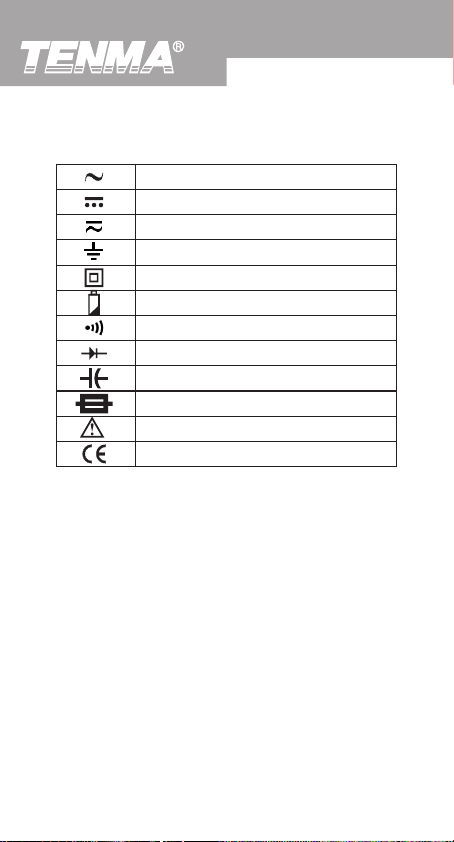
International Electrical Symbols
AC (Alternating Current).
DC (Direct Current).
AC or DC.
Grounding.
Double Insulated.
Deficiency of Built-In Battery.
Continuity Test.
Diode.
Capacitance Test.
Fuse.
Warning. Refer to the Operating Manual.
Conforms to Standards of European Union.
8
Page 9
Page 10

Page 11
Page 12
Page 13
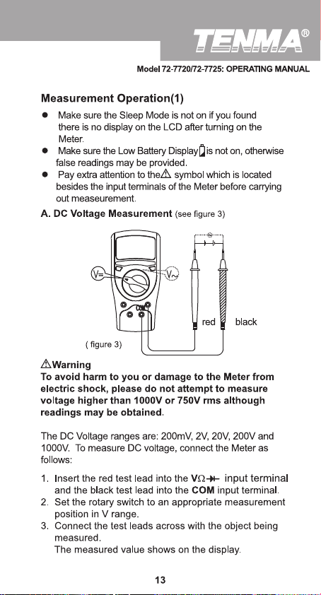
Page 14
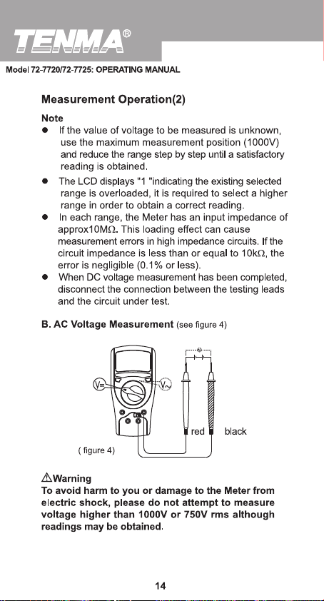
Page 15
Page 16
Page 17
Model 72-7720/72-7725: OPERATING MANUAL
Measurement Operation(5)
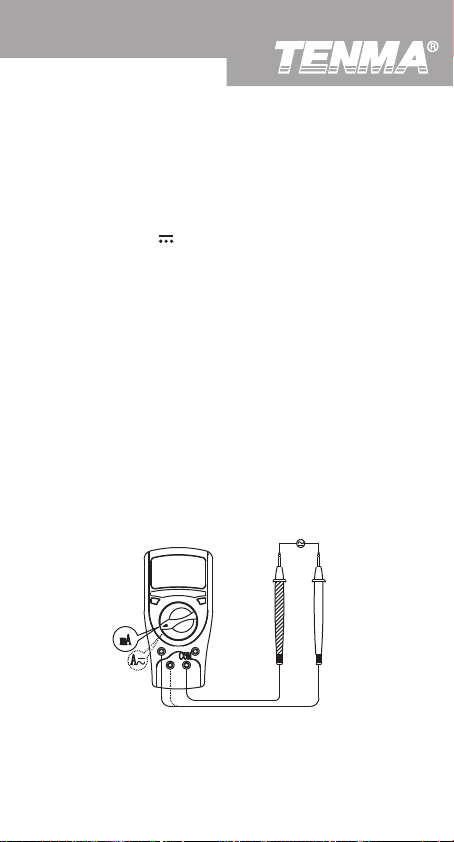
2. Insert the red test lead into the µAmA ( Model
72-7725) or 20A terminal and the black test lead into
the COM terminal.
3. Set the rotary switch to an appropriate measurement
position in A range.
4. Break the current path to be tested. Connect the red
test lead to the more positive side of the break and
the black test lead to the more negative side of the
break.
5. Turn on power to the circuit. The measured value
shows on the display.
Note
l If the value of current to be measured is unknown,
use the maximum measurement position (20A) and
20A terminal, and reduce the range step by step until
a satisfactory reading is obtained.
l When current measurement has been completed,
disconnect the connection between the test leads
and the circuit under test.
D. AC Current Measurement (see figure 6)
black
red
( figure 6)
17
Page 18

Model 72-7720/72-7725: OPERATING MANUAL
Measurement Operation(6)
Warning
Never attempt an in-circuit current measurement
where the voltage between terminals and ground is
greater than 60V.
If the fuse burns out during measurement, the Meter
may be damaged or the operator may be injured.
Use proper terminals, function, and range for the
measurement. When test leads are connected to the
current terminals, do not place them in parallel
across any circuit.
Model 72-7720: The AC current measurement has five
measurement positions on the rotary switch: 200µA,
2mA, 20mA, 200mA and 20A.
Model 72-7725: The AC current measurement has three
measurement positions on the rotary switch: 20mA,
200mA and 20A.
To measure current, do the following:
1. Turn off power to the circuit.Discharge all high-voltage
capacitors.
2. Insert the red test lead into theµAmA ( Model
72-7720) or mA ( Model 72-7725) or 20A terminal
and the black test lead into the COM terminal.
3. Set the rotary switch to an appropriate measurement
position in A range.
4. Break the current path to be tested. Connect the red
test lead to the more positive side of the break and
the black test lead to the more negative side of the
break.
5. Turn on power to the circuit.
The measured value shows on the display.
Note
l If the value of current to be measured is unknown,
use the maximum measurement position (20A) and
20A terminal and reduce the range step by step until
a satisfactory reading is obtained.
l When current measurement has been completed,
disconnect the connection between the testing leads
and the circuit under test.
18
Page 19
Model 72-7720/72-7725: OPERATING MANUAL
Measurement Operation(7)
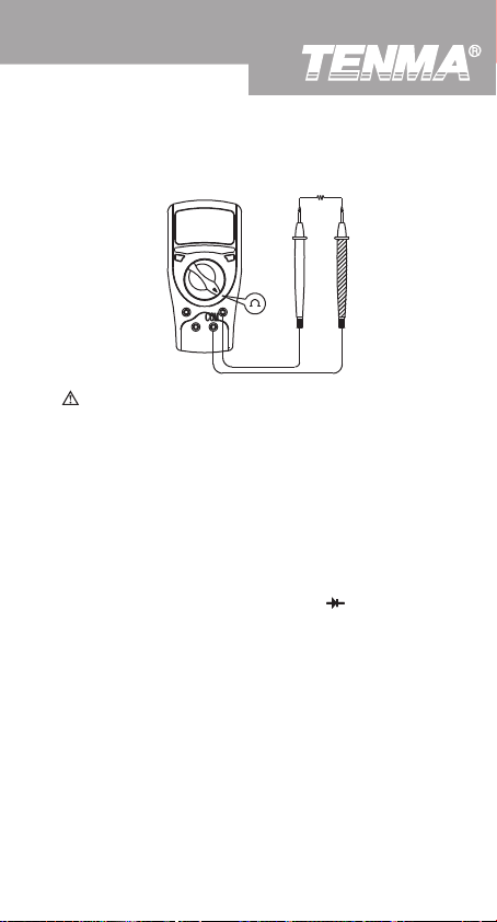
E. Measuring Resistance (see figure 7)
red black
( figure 7)
Warning
To avoid damage to the Meter or to the devices under
test, disconnect circuit power and discharge all the
high-voltage capacitors before measuring resistance.
The resistance ranges are:
Model 72-7720: 200Ω, 2kΩ, 20kΩ, 200kΩ,
2MΩ, 20MΩand 200MΩ.
Model 72-7725: 200Ω, 2kΩ, 20kΩ, 200kΩ, 2MΩ
and 200MΩ.
To measure resistance, connect the Meter as follows:
1. Insert the red test lead into the VΩ terminal and
the black test lead into the COM terminal.
2. Set the rotary switch to an appropriate measurement
position inΩ range.
3. Connect the test leads across with the object being
measured.The measured value shows on the display.
Note
l The test leads can add 0.1Ωto 0.3Ω of error to the
resistance measurement.T o obtain precision readings
in low-resistance, that is the range of 200Ω, short circuit the input terminals beforehand and record the
reading obtained (called this reading as X). (X) is
the additional resistance from the test lead.
19
Page 20
Model 72-7720/72-7725: OPERATING MANUAL
Measurement Operation(8)
l For high resistance (>1MΩ), it is normal to take
several seconds to obtain a stable reading.
l When there is no input, for example in open circuit
condition, the Meter displays “1”.
l When resistance measurement has been completed,
disconnect the connection between the testing leads
and the circuit under test.
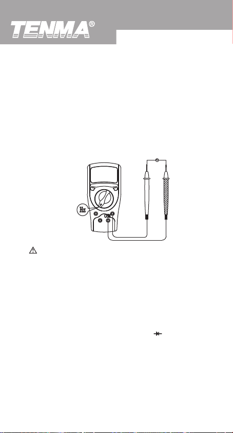
F . Model 72-725: Frequency Measurement (see figure 8)
red black
( figure 8)
Warning
To avoid harm to you or damage to the Meter, do
not attempt to measure voltages higher than 60V in
DC or 30V rms in AC although readings may be
obtained. When the frequency signal to be tested is
higher than 30V rms, the Meter cannot guarantee
accuracy of the measurement.
The frequency measurement ranges are 2kHz and 20kHz.
To measure frequency, connect the Meter as follows:
1. Insert the red test lead into the VΩ terminal and
the black test lead into the COM terminal.
2. Set the rotary switch to an appropriate measurement
position in kHz range.
3. Connect the test leads across with the object being
measured.
The measured value shows on the display.
20
Page 21
Model 72-7720/72-7725: OPERATING MANUAL
Measurement Operation(9)
Note
l When Hz measurement has been completed,
disconnect the connection between the testing leads
and the circuit under test.
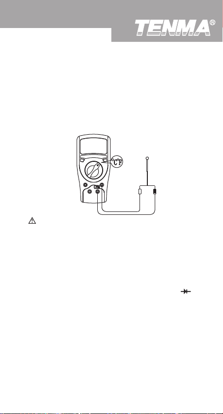
G. Model 72-7725: Temperature Measurement
(see figure 9)
( figure 9)
Warning
To avoid harm to you or damage to the Meter, do
not attempt to measure voltages higher than 60V in
DC or 30V rms in AC although readings may be
obtained.
The temperature measurement range is from -40 oC~
1000 oC or -40 oF~1832 oF. To measure temperature,
connect the Meter as follows:
1. Insert the red temperature probe into the V Ω
terminal and the black temperature probe into the COM
terminal.
2. Set the rotary switch to oC or oF.
3. Place the temperature probe to the object being
measured.
The measured value shows on the display.
Note
l The Meter automatically displays the temperature
value inside the Meter when there is no temperature
probe connected.
21
Page 22
Model 72-7720/72-7725: OPERATING MANUAL
Measurement Operation(10)
l The included temperature probe may only be used for
measurment up to 250oC For any mesaurement
higher than that, the rod type temperature probe
must be used .
l When temperature measeuremnet has been completed,
disconnect the connection between the testing leads
and te circuit under test.
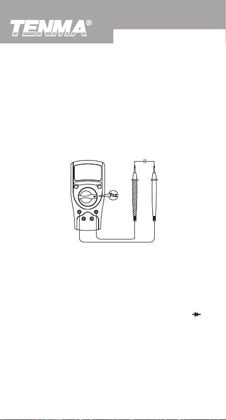
H.Capacitance Measurement (see figure 10)
( figure 10)
Model 72-7720:Capacitance measurement has four
measurement positions on the rotary switch : 2nF , 20nF,
2µF and 100µF .
Model 72-7725: Capacitance measurement has four
measurement positions on the rotary switch: 20nF ,
200nF , 2µF and 100µF.
To measure capacitance, connect the Meter as follows:
1. Insert the red test clip or red test lead into the VΩ
terminal and the black test clip or black test lead into
the µmA ( Model: 72-7720) or mA ( Model: 72-7725)
terminal.
2. Set the rotary switch to an appropriate measurement
position in Fcx range.
3. Connect the test leads across with the object being
measured.
The measured value shows on the display.
22
Page 23
Model 72-7720/72-7725: OPERATING MANUAL
Measurement Operation(11)
Note
l When testing polarited capacitors , connect the
red test lead to anode & black test lead to cathode
l If the capacitor is shorted or the capacitor
value is overloaded, the LCD will display “1”.
l To minimize the error , the test lead should be as
short as possible.
When the tested capacitor is greater than 30 µF ,
reading is for reference only.
l It is normal to take a while for zeroing when changing
the measurement range. This process will not affect
the accuracy of the final readings obtained.
I. Measuring Diodes & Continuity
Warning
To avoid damage to the Meter or to the equipment
under test, disconnect circuit power and discharge
all high-voltage capacitors before measuring diodes
and continuity.
Testing Diodes
Use the diode test to check diodes, transistors, and other
semiconductor devices. The diode test sends a current
through the semiconductor junction, and then measures
the voltage drop across the junction. A good silicon
junction drops between 0.5V and 0.8V.
To test out a diode out of a circuit, connect the Meter as
follows:
1. Insert the red test lead into the VΩ terminal and
the black test lead into the COM terminal.
2. Set the rotary switch to
3. For forward voltage drop readings on any semiconductor
component, place the red test lead on the component’s
anode and place the black test lead on the component’s
cathode.
The measured value shows on the display.
.
23
Page 24

Model 72-7720/72-7725: OPERATING MANUAL
Measurement Operation(12)
Note
l In a circuit, a good diode should still produce a forward
voltage drop reading of 0.5V to 0.8V; however; the
reverse voltage drop reading can vary depending on
the resistance of other pathways between the probe
tips.
l Connect the test leads to the proper terminals as said
above to avoid error display. The LCD will display
“1” indicating open-circuit for wrong connection.
The unit of diode is Volt (V), displaying the positive connection voltage-drop value.
l When diode testing has been completed, disconnect
the connection between the testing leads and the
circuit under test.
Testing for Continuity
To test for continuity, connect the Meter as below:
1. Insert the red test lead into VΩ terminal and the
black test lead into the COM terminal.
2. Set the rotary switch to
3. Connect the test leads across with the object being
measured.
The buzzer sounds if the resistance of a circuit under
test is less than 70Ω .
The LCD displays the resistance value of a circuit under
test.
Note
l The LCD display “1” indicating the circuit being
tested is open.
l When continuity testing has been completed,
disconnect the connection between the testing leads
and the circuit under test.
.
24
Page 25

Model 72-7720/72-7725: OPERATING MANUAL
Sleep Mode
Turning on the Auto Display Backlight
The Meter has a built-in sensor. Therefore the Display
Backlight turns on and off automatically depending on
the brightness of the environment.
25
Page 26
Model 72-7720/72-7725: OPERATING MANUAL
General Specifications
l Maximum voltage between
any Terminals and
Ground : 1000V rms.
l
Fused Protection for
mA Input Terminal : 0.5A, 250V fast
type, 5x20mm.
l
Fused Protection for 20A
Input Terminal : Un-fused.
l Range : Manual ranging.
l Maximum Display : Display :1999.
l Mesaurement Speed : Updates 2~3 times/second.
l Temperature : Operating: 0oC~40oC
(32oF~104oF);
Storage : -10oC~50oC( 14oF~122oF).
l Relative Humidity :
l Altitude: Operating : 2000m;
Storage : 10000m.
l Battery Type : 9V NEDA1604 or 6F22
or 006P.
l Low Battery : Display “
l Data Hold : Display “
l Negative read : Display “ ”
l Overload : Display “1”.
l Dimensions (HxWxL) : 165x80x38.3mm.
l Weight : Approx.275g (battery
included).
l Safety/Compliances : IEC61010 CAT II 1000V
overvoltage and double
insulation standard.
l Certificate :
75% @ 0oC~30oC;
50% @ 31oC~40oC.
”.
”
26
Page 27
Model 72-7720/72-7725: OPERATING MANUAL
Accuracy Specifications(1)
Accuracy: (a% reading + b digits),guarantee for 1 year.
Operating temperature:23oC
Relative humidity:<75%.
T emperature coef ficient: 0.1 x (specified accuracy) / 1oC.
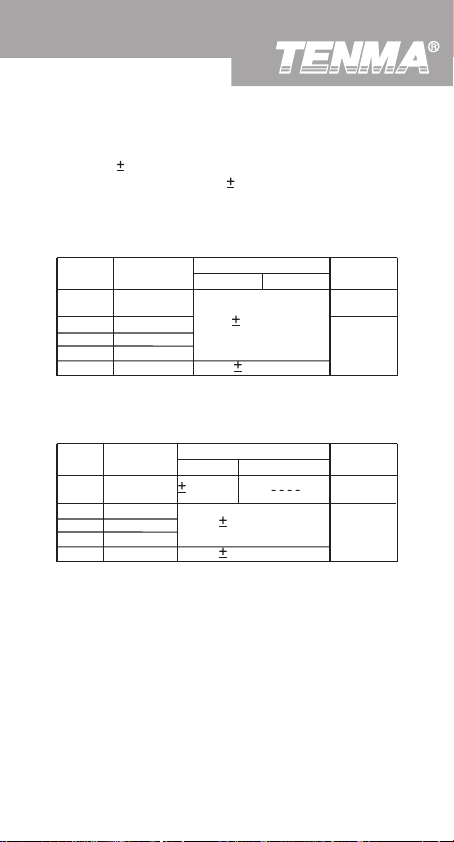
A. DC Voltage
Range Resolution
2V
20V
100µV
1mV
10mV
100mV
1V
Resolution
100µV
1mV
10mV
100mV
1V
200mV
200V
1000V
Remark: Input impedance: 10MΩ
B. AC Voltage
Range
200mV
2V
20V
200V
750V
Remarks:
l Input impedance: 10MΩ .
l Frequency response: 40Hz~400Hz.
l Display effective value of sine wave (mean value
response).
5oC.
Accuracy
72-7720 72-7725
(0.5%+1)
(0.8%+2)
Accuracy
72-7720 72-7725
(1.2%+3)
(0.8%+3)
(1.2%+3)
Overload
Protection
250VDCor
ACrms.
1000V DC
or 750V AC
rms.
Overload
Protection
250V DC or
AC rms
1000V DC
or 750V
AC rms.
27
Page 28
Model 72-7720/72-7725: OPERATING MANUAL
Accuracy Specifications(2)
C. DC Current
Range
20µA
2mA
20mA
200mA
20A
Resolution
72-7720 727-7725
0.01µA
1µA
10µA
100µA
10mA
Remarks:
l At 20A Range: For continuous measurement
seconds and interval not less than 15 minutes.
l Measurement voltage drop: Full range at 200mV.
D. AC Current
Range
Resolution
200µA
20mA
200mA
2mA
20A
0.1µA
1µA
10µA
100µA
10mA
Remarks:
l At 20A Range: For continuous measurement
seconds and interval not less than 15 minutes.
l Measurement voltage drop: Full range at 200mV.
l Frequency reaponse: 40Hz~400Hz
l Display effective value of sine wave (mean value
response).
Accuracy
(0.8%+1)
(0.8%+1)
(1.5%+1)
(2%+5)
Accuracy
72-7720 72-7725
(1%+3)
(1%+3)
(1.8%+3)
(3%+5)
Overload
Protection
0.5A. 250V
fast type
fuse, 5x20
mm
Un-Fused
Overload
Protection
0.5A. 250V
fast type
fuse, 5x20
mm
Un-Fused
10
10
28
Page 29
Model 72-7720/72-7725: OPERATING MANUAL
Accuracy Specifications(3)
E. Resistance Test
Range
Resolution
200Ω
2kΩ
20kΩ
200kΩ
2MΩ
20MΩ
200MΩ
Remarks:
l Open circuit voltage:
it is approx. 2.8V)
l At 200MΩ range , test lead is in short circuit , and it
is normal to display 10 digits. During measurement,
subtract the 10 digits from the reading.
F. Model 72-7725: Frequency
Range Resolution Accuracy Overload Protection
2kHz
20kHz
Remarks: Input Sensitivity: 200mV.
G. The Model 72-7725: Temperature
Range
-40oC~0oC
0oC~400oC
400oC~1000oC
-40oF~32oF
32oF~752oF
752oF~1832oF
0.1Ω
1Ω
10Ω
100Ω
1kΩ
10kΩ
100kΩ
1Hz
10Hz
Resolution
1oC
1oF
Accuracy
72-7720 72-7725
(0.8%+3)
(0.8%+1)
(1%+2)
[5%(reading-10)+10]
700mV (At 200MΩ range,
(2%+5)
(1.5%+5)
Accuracy
(3%+3)
(1%+3)
2.5%
(3%+4)
(1%+4)
(1.5%+15)
Overload
Protection
or AC rms
250V AC
Overload
Protection
250V DC
250V AC
29
Page 30
Model 72-7720/72-7725: OPERATING MANUAL
Accuracy Specifications(4)
H. Capacitance
Range
2nF
20nF
200nF
2µF
100µF
Resolution
1pF
10pF
0.1nF
1nF
0.1µF
Accuracy
72-7720 72-7725
(4%+3)
(4%+3)
(5%+4)
(4%+3)
Remarks:Testing signal:approx. 400Hz 40mV rms.
When the tested capacitor is greater than 30 µF,
reading is for reference only.
I. Diodes and Continuity Test
Range Resolution Input Protection Remark
1mV
250V DC or AC
1Ω
Overload
Protection
250V AC
Open circuit
voltage approx.2.8V
30
Page 31
Model 72-7720/72-7725: OPERATING MANUAL
Maintenance(1)
This section provides basic maintenance information
including battery and fuse replacement instruction.
Warning
Do not attempt to repair or service your Meter unless
you are qualified to do so and have the relevant
calibration, performance test, and service information.
To avoid electrical shock or damage to the Meter, do
not get water inside the case.
A. General Service
l Periodically wipe the case with damp cloth and mild
detergent. Do not use chemical solvent.
l T o clean the terminals with cotton bar with detergent,
as dirt or moisture in the terminals can affect readings.
l Turn the Meter OFF when it is not in use and take
out the battery when not using for a long time.
l Do not store the Meter in place of humidity, high
temperature, explosive, inflammable and strong
magnetic field
B. Replacing the Battery (see figure 11)
(figure 11)
31
Page 32

Model 72-7720/72-7725: OPERATING MANUAL
Maintenance(2)
Warning
To avoid false readings, which could lead to possible
electric shock or personal injury,replace the battery
as soon as the battery indicator appears.
To replace battery:
1. Disconnect the connection between the test leads
and the circuit under test, and move the test leads
away from the input terminals of the Meter.
2. Turn the Meter OFF
3. Remove the rubber feet and screws from the battery
compartment, and separate the battery compartment
from the case bottom
4. Remove the battery from the battery compartment.
5. Replace the battery with a new 9V battery (NEDA
1604 or 6F22 or 006P).
6. Rejoin the battery compartment and the case bottom,
and install the screw and rubber feet
C. Replacing the Fuses
Warning
To avoid electrical shock, arc blast, personal
injury or damage to the Meter, use specified fuses
ONLY in accordance with the following procedure.
To replace the Meter’s fuse:
1. Disconnect the connection between the test leads
and the circuit under test, and move the test leads
away from the input terminals of the Meter.
2. Turn the Meter OFF.
3. Remove the rubber feet and screws from the case
bottom, and separate the case bottom from the case
top.
4. Remove the fuse by gently prying one end loose,
and then take out the fuse from its bracket.
32
Page 33

Model 72-7720/72-7725: OPERATING MANUAL
Model UT50A/B/C: OPERATING MANUAL
Maintenance(3)
1. Install ONLY replacement fuses with the identical
type and specification as follows and make sure the
fuse is fixed firmly in the bracket. 0.5A. 250V fast
type fuse, φ 5x20mm.
2. Rejoin the case bottom and the case top, and install
the screw and rubber feet
Replacement of fuses is seldom required. Burning of a
fuse always results from the improper operation.
This operating manual is subject to change without notice.
This operating manual is subject to change without notice.
~ END ~
33
Page 34

Model 72-7720/72-7725: OPERATING MANUAL
Tenma Test Equipment
405 S. Pioneer Blvd.
Springboro,Ohio 45066
www.tenma.com
34
 Loading...