


72-6696 Spectrum Analyzer
Spectrum Analyzer
72-6696
Operation Manual
8272-66960M0
0

72-6696 Spectrum Analyzer
Table of Contents |
|
1.0 GENERAL DESCRIPTION AND FEATURES........................................................................................ |
3 |
2.0 USAGE PRECAUTIONS AND RECOMMENDATIONS ........................................................................ |
3 |
3.0 PANEL DESCRIPTIONS........................................................................................................................ |
7 |
4.0 SETUP AND USE ................................................................................................................................. |
11 |
5.0 QUICK USE INDEX .............................................................................................................................. |
27 |
6.0 SPECIFICATIONS................................................................................................................................ |
28 |
APPENDIX 1 - REMOTE OPERATION...................................................................................................... |
31 |
Due to continuous improvements in the 72-6696 Spectrum Analyzer, information contained in this Manual is subject to change without notice.
1
72-6696 Spectrum Analyzer
1.0 General Description and Features
The 72-6696 is designed for minimal set-up and adjustment. The user interface allows fast and accurate measurements. The fully synthesized design of the 72-
6696 permits stable operation down to 2 kHz / division.
2.0 Usage Precautions and Recommendations
The following precautions are recommended to insure your safety and to provide the best condition of the 72-6696.
Safety Terms and Symbols
These terms may appear in this manual or on the product:
WARNING: Warning statements identify condition or practices that could result in injury or loss of life.
CAUTION: Caution statements identify conditions or practices that could result in damage to this product or other property.
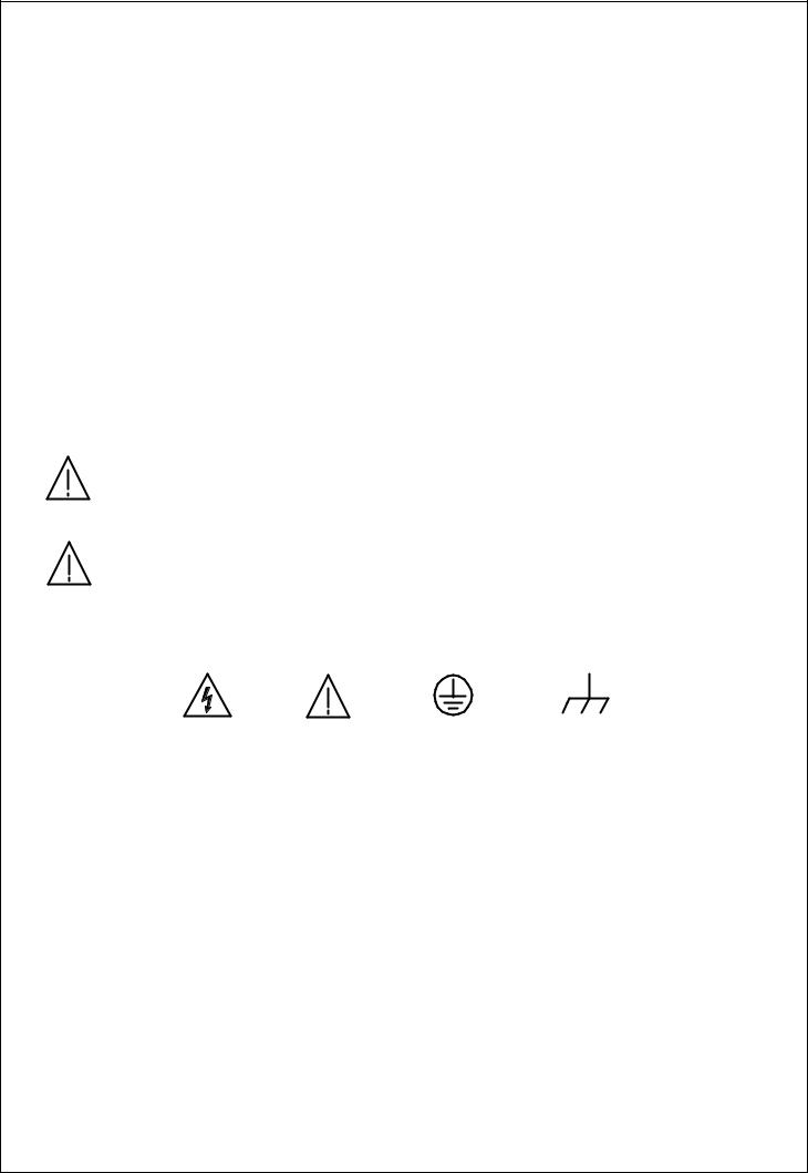
The following symbols may appear in this manual or on the product:
DANGER |
ATTENTION |
Protective |
Earth (ground) |
High Voltage |
refer to Manual |
Conductor |
Terminal |
|
|
Terminal |
|
2

72-6696 Spectrum Analyzer
FOR UNITED KINGDOM ONLY
NOTE: This lead / appliance must only be wired by competent persons
WARNING: THIS APPLIANCE MUST BE EARTHED
IMPORTANT: The wires in this lead are coloured in accordance with the following code:
Green/ Yellow: |
Earth |
Blue: |
Neutral |
Brown: |
Live (Phase) |
As the colours of the wires in main leads may not correspond with the colours marking identified in your plug/appliance, proceed as follows:
The wire which is coloured Green & Yellow must be connected to the Earth terminal marked with the letter E or by the earth symbol  or coloured Green or
Green & Yellow.
The wire which is coloured Blue must be connected to the terminal which is marked with the letter N or coloured Blue or Black.
The wire which is coloured Brown must be connected to the terminal marked with the letter L or P or coloured Brown or Red.
If in doubt, consult the instructions provided with the equipment or contact the supplier.
This cable/appliance should be protected by a suitably rated and approved HBC mains fuse: refer to the rating information on the equipment and/or user instructions for details. As a guide, cable of 0.75mm2 should be protected by a 3A or 5A fuse. Larger conductors would normally require 13A types, depending on the connection method used.
Any moulded mains connector that requires removal /replacement must be destroyed by removal of any fuse & fuse carrier and disposed of immediately, as a plug with bared wires is hazardous if a engaged in live socket. Any re-wiring must be carried out in accordance with the information detailed on this lable.
3

72-6696 Spectrum Analyzer
Use and Wear
CAUTION
•Do not exceed +30 dBm into the RF INPUT or +30 dBm reverse power into the
TG OUTPUT.
•Do not place any heavy object on the instrument.
•Avoid severe impacts or rough handling that could damage the 72-6696.
•Use electrostatic discharge precautions while handling and making connections to the 72-6696.
•Do not place wires into the connectors of the 72-6696, only mating connectors and adapters.
•Do not block or obstruct cooling fan vent opening on side panels or on the rear panel of unit.
1) Disassembly of the Instrument
• Do not disassemble the instrument; refer the instrument to a factory approved service facility only.
2) AC Power Input
CAUTION
•AC input should be within the range of selected line voltage +/- 10%.
•Insure the correct fuse is installed prior to applying voltage for the first time -
90 V ~ 132 VAC input : T 1A / 250V
198 ~ 250 VAC input : T0.5A / 250V
•Check the line voltage setting on the rear panel. If the line voltage does not match input voltage, change as follows:
a)Remove AC Power Cord;
b)Open cover of AC socket with flat blade screwdriver;
c)Remove selector Cam Drum and rotate to the correct voltage selection
d)Replace Cam Drum.
4

72-6696 Spectrum Analyzer
3) Grounding
WARNING
•To avoid electrical shock, the power cord protective grounding conductor must be connected to earth ground.
4) Fuse Replacement
WARNING
•For continued fire protection, replace the fuse with the specified type and rating only.
•Disconnect power cord before replacing fuse.
•If the fuse is blown, there is something wrong with the instrument. Repair the cause of fault before replacing fuse.
5) Cleaning
•Disconnect AC Power Cord from the instrument before cleaning.
•Use a soft cloth dampened in a solution of mild detergent and water. Do not spray any liquid into the unit.
•Do not use chemicals or cleaners containing benzene, toluene, xylene, acetone or other harsh chemicals.
6) Operating Environment
•The following conditions are recommended for optimum use of the instrument -
Indoor Use |
Altitude < 2000 m |
Temperature 18° to 28° C Relative Humidity < 90% |
Dust Free |
No direct sunlight |
No strong magnetic fields |
•Installation Category: II
• Pollution degree: 2
7) Storage Environment
•The following conditions are recommended for optimum storage of the instrument -
Indoor Temperature 0° to 40° C |
Relative Humidity < 85% |
5

72-6696 Spectrum Analyzer
3.0 Panel Descriptions
Front Panel
6

72-6696 Spectrum Analyzer
7

|
72-6696 Spectrum Analyzer |
Item |
Description |
1 |
Cathode Ray Tube (CRT) Display, 8 x 10 graticule, 5 inch |
2 |
Liquid Crystal Display (LCD), 4 line x 20 character |
3 |
Keypad, field selection and data entry |
4 |
Spinner, field selection and data change |
5 |
RF Input, Coaxial, Type N Female |
6 |
Tracking Generator Output, Coaxial, Type N Female (optional) |
7 |
Switch, Power ON / OFF |
8 |
Adjustment, CRT Trace Rotation, potentiometer |
9 |
Control Knob, Volume (optional demod receiver) |
10 |
Phone Jack, head set output, (optional demod receiver) |
11 |
Control Knob, CRT Focus |
12 |
Adjustment, CRT Y-axis position, potentiometer |
13 |
Control Knob, CRT Intensity |
8

72-6696 Spectrum Analyzer
Rear Panel
9
|
72-6696 Spectrum Analyzer |
Item |
Description |
14 |
Panel Label, Usage Warning |
15 |
External Frequency Reference Input, BNC (optional) |
16 |
Connector, DB9, Female, RS-232 |
17 |
Panel Label, Serial Number |
18 |
Cooling Fan Vent |
19 |
Adjustment, CRT Trace Rotation, potentiometer |
20 |
Adjustment, Internal Frequency Reference , potentiometer |
21 |
Adjustment, LCD Contrast, potentiometer |
22 |
Panel Label, Input Voltage |
23 |
AC Input, Connector, Voltage Select and Fuse |
10
 Loading...