

Tenma 72-7655 User Manual
Tenma Model 72-7655
High Current Switch Mode Power Supply with Remote Sensing and Control
User Manual
1. INTRODUCTION
This 900W switching mode DC regulated dual output power supply series provides high current with
constant current limiting protection
, and variable output of 1.0 ~ 15VDC. It is designed with a highly efficient
Active Power Factor Corrector. The remote sensing terminal is used to compensate for long output line losses.
The output voltage level can be externally controlled via the remote control terminal.
2. PRECAUTIONS
● Never Short the Remote Sensing Terminal
● This power supply is for Indoor Use Only.
● Do not expose the power supply to
sun, humid or dusty environment.
● Never remove the metal cover of the power supply while AC power is connected.
● Never touch the unit when your hands are wet.
● Never block the ventilation slots and cooling fan air intake window
● Never attempt to repair the power supply. Incorrect re-assembly may result in a risk of electric shock or
fire.
● Never use the power supply for the load requiring higher current than the designed value otherwise it
may damage the power supply.
● Place the power supply on a flat surface with sufficient clearance, dry, dust free surroundings for
ventilation.
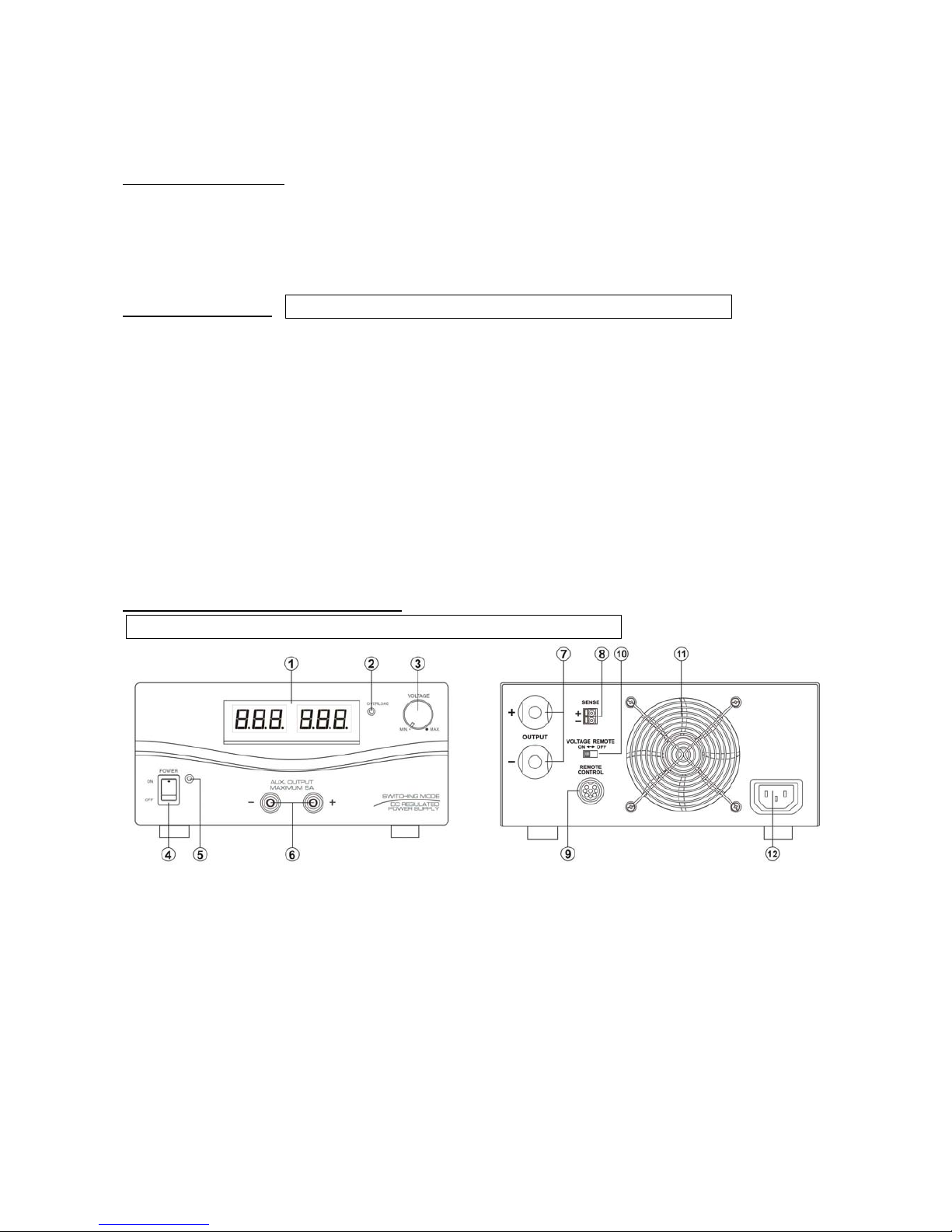
3. CONTROLS AND INDICATORS
(1) Voltage & Ammeter LED Display
(2) Overload LED Indicator – Overload(Constant Current Limiting) & Short-Circuit Protection
(3) Output Voltage Control Knob(control both main and auxilary output)
(4) Power ON/OFF Switch
(5) Power ON/OFF LED
(6) Auxiliary Output Terminal: Rated 5A
(7) Main Output Terminal: Rated 60A
(8) Remote Sensing Terminal (Warning! : Never short the remote sensing terminal)
(9) Remote Control Terminal
(10) Remote Control ON/OFF Switch
(11) Cooling Fan Air Intake Grille
(12) AC Input Plug
Front Rear
Note: Main and Auxiliary output give out same output voltage
CAUTION! : The AC Input is DOUBLE POLE FUSED
4. CONNECTION
4.2 Check the rating label of the power supply and make sure it complies with your AC mains voltage.
Connect the power supply to the AC Mains using the provided power cord.
Steps 4.3 & 4.4 explain how to use the special features: remote sensing and remote control.
You can use the 2 features at the same time or separately.
Please go to step 4.5 if you do not use the 2 features and make sure the remote control
ON/OFF switch is in OFF position(rear panel).
4.3 REMOTE SENSING – Take note of the warning and follow the order of installation.
Warning!:Never short the Remote Sensing Terminal
Connection:
1. First complete the power connections between power supply and equipment.
2. Check and make sure the power connections are secure.
3. Then make connections between Remote Sensing and equipment.
Warning!:Never short the Remote Sensing Terminal
Dis-connection:
1. First disconnect the remote sensing connections.
2. Then disconnect the power connections between the power supply and equipment.
Fig 3 showing connections between Remote Sensing, Power output and Equipment.
The remote sensing wire should be AT LEAST 22AWG wire size.
4.4 REMOTE CONTROL
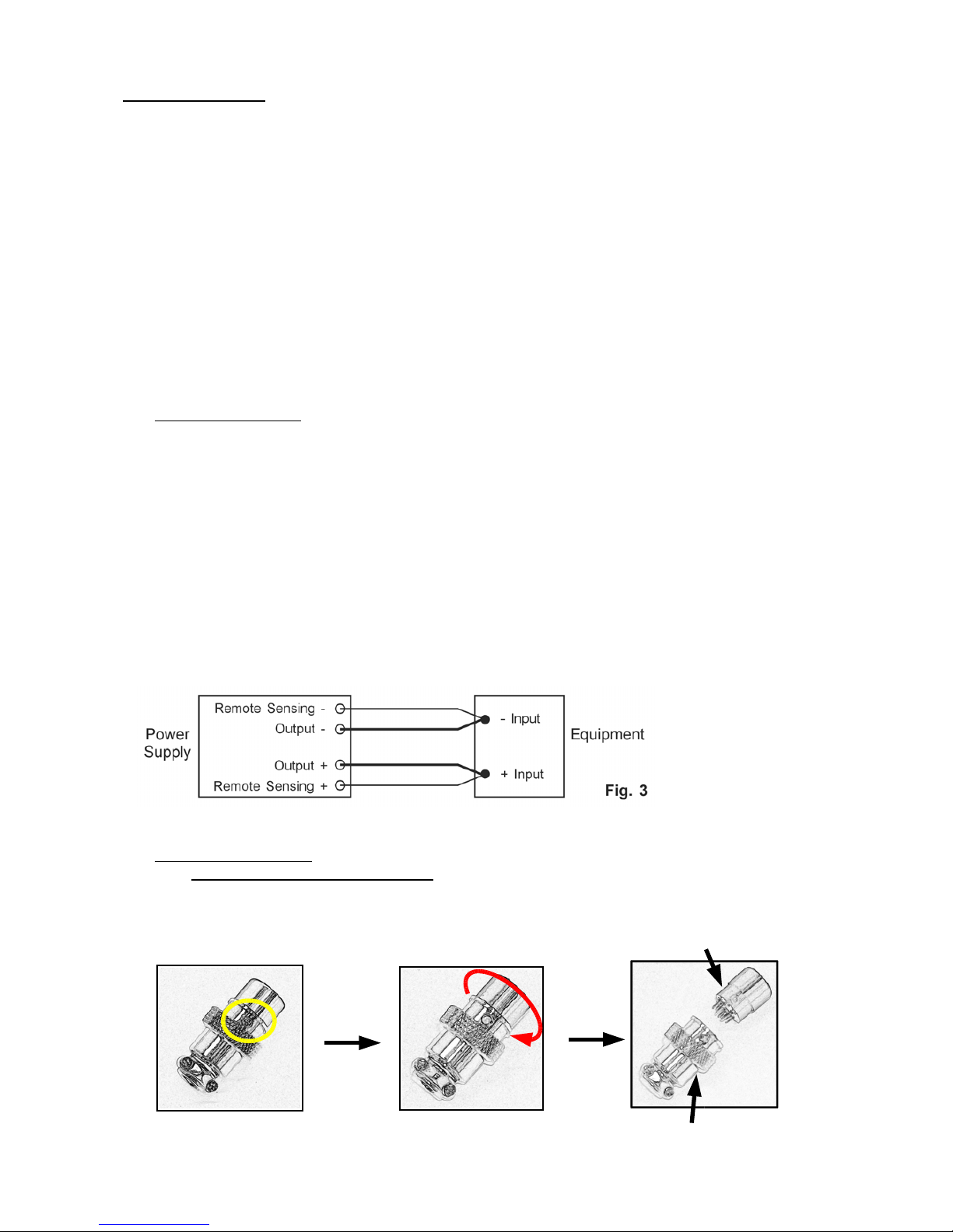
4.4.1 VOLTAGE REMOTE CONTROL
Set up the provided remote connector plug
(a) Remove the black portion of the remote control connector plug by removing the screw as Fig 4.
Black portion
Silver portion
Fig. 4
2. Rotate the black portion1. Remove the screw
4.1
(Intentionally left blank for this model)
 Loading...