

CoaxManager™
User Guide
Ref.769202 CoaxData™ 1Gbps HDTV
con SFP
Ref.769201 CoaxData™ 1Gbps HDTV

Content Index
Important safety instructions.................................................................................................................... 4
General installation conditions.....................................................................................................................4
How to use the equipment safely.................................................................................................................4
Electrical safety symbols..............................................................................................................................4
Introduction............................................................................................................................................... 5
Application Description................................................................................................................................ 5
Features.......................................................................................................................................................5
System Requirements .................................................................................................................................5
Supported CoaxDATA Devices....................................................................................................................5
Installing CoaxManager Application......................................................................................................... 6
Connecting CoaxDATA Modem to CoaxManager .......................................................................................7
Device Configuration................................................................................................................................ 8
MDU Configuration...................................................................................................................................... 9
Select Transmission medium.....................................................................................................................10
Transmission Mask.................................................................................................................................... 11
Writing Device Settings .............................................................................................................................12
Checking Devices Network.................................................................................................................... 13
Device Info.................................................................................................................................................13
CCO Info....................................................................................................................................................14
Network Topology...................................................................................................................................... 14
Generating traffic to verify network links ...................................................................................................15
Generating Reports for Checking Network State...................................................................................... 16
Setting QoS parameters (Advanced User) ............................................................................................ 18
Default Priorities.........................................................................................................................................18
Priority Levels Assignment.........................................................................................................................19
TTL - Time to Live......................................................................................................................................19
Buffer Allocation, Priority Thresholds.........................................................................................................20
Bandwidth Limit..........................................................................................................................................21
Bandwidth Limit with QoS..........................................................................................................................21
Setting Advanced Configuration ........................................................................................................... 23
IGMP options............................................................................................................................................. 23
Number of Users per Slave........................................................................................................................ 25
Network Mitigation..................................................................................................................................... 25
Factory Defaults Button............................................................................................................................. 27
Advanced Power Management..................................................................................................................27
Advanced MME Features.......................................................................................................................... 27


CoaxManager™ User Guide
Important safety instructions
General installation conditions
Before handling or connecting the equipment,please read this manual.
In order to reduce the risk of fire or electric shock, do not expose the equipment to rain or
moisture.
Do not take the cover off the equipment without disconnecting it from the AC power.
4
Do not obstruct the equipment’s ventilation system.
Please allow air circulation around the equipment.
The equipment must not come into contact with water or even be splashed by liquids. Do not
place containers with water on or near the equipment if it is not adequately protected.
Do not place the equipment near sources of heat or in excessively moisture conditions.
Do not place the equipment where it may be affected by strong vibrations or knocks.
How to use the equipment safely
The powering supply of this product is: 100-264 Vac~ 50/60 Hz.
If any liquid or object falls inside the equipment, please contact a specialized technician.
To disconnect the equipment from the mains, pull from the connector, and never pull from the
cable.
Do not connect the equipment to the mains until all the other connections have been made.
The AC Power socket that is going to be used to connect the equipment should be located
nearby and should be easily accessible.
Electrical safety symbols
EN
This symbol indicates compliance with the requirements of CE mark.
This symbol indicates that the equipment is for indoor use only.
This symbol indicates that the equipment complies with the safety requirements for
class II equipment.
www.televes.es

Televes
5
Introduction
Application Description
CoaxManager™ software allows CoaxDATA™ device configuration, setting different modes of
operation, checking installation state and links between devices. CoaxManager™ also allows
configuration of QoS parameters, and other options such as activation of low-power modes for energy
efficiency,
Features
Check coax or PLC installation obtaining links status and traffic rates between devices.
Create PDF reports of network status for later analysis.
Allows basic device configuration setting MxU/HomeNetworking operating modes.
Set Network password for create several system networks. You can install up to four masters
(each with a different key) on the same coaxial network.
®
EN
Allows configuration of QoS parameters supporting four priority levels based on IEEE 802.1Q
VLAN tags or IPv4 ToS (Type of Service).
Supports Advanced Features to configure IGMP, number of users or Low Power Mode.
System Requirements
Application works with Windows 2000/XP/Vista/7/8
Application works on Mac OS X and Linux Operating systems with virtualization based on
Oracle VM VirtualBox software for Windows 2000/XP/Vista/7/8.
Application requires installation of additional Winpcap library (http://www.winpcap.org/install/
default.htm). If library is not installed, CoaxManager automatically install on your PC.
System is fully Plug & Play and requires no installation of any additional software or drivers.
Supported CoaxDATA Devices
Following CoaxDATA devices are supported by application:
• Ref.7689 CoaxDATA™ 200Mbps-HDTV
• Ref.768973 CoaxDATA™ 200Mbps-HDTV 1xEth
• Ref.769201 CoaxDATA™ 1Gbps-HDTV
• Ref.769202 CoaxDATA™ 1Gbps-HDTV with SFP
• Ref.769203 CoaxDATA™ 1Gbps-HDTV 1XEth
www.televes.es
CoaxManager™ User Guide
6
Installing CoaxManager Application
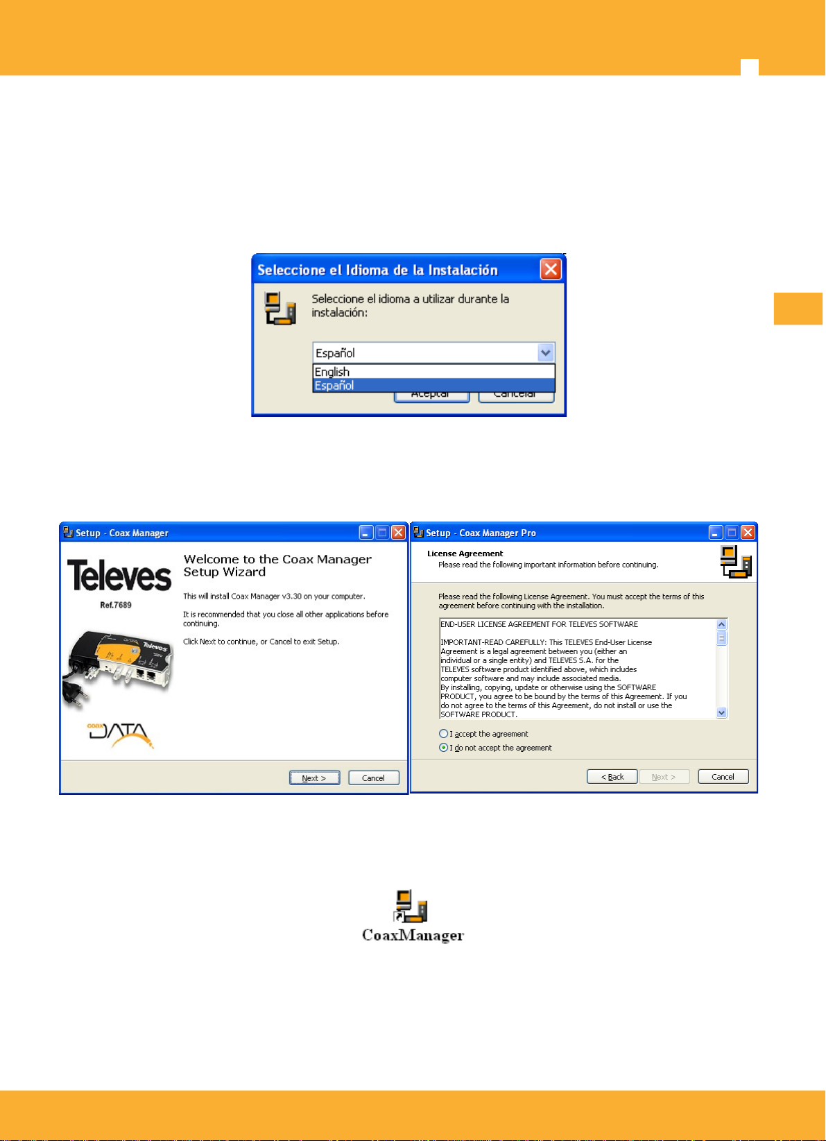
CoaxManager application installed through an executable that guide the user through the installation
process.
Language selection: This option selects setup language
EN
Follow installer instructions to complete applcation installation. Read carefully license before use
program and approval before continue.
Once installed application will appear on your desktop the icon below:
www.televes.es
Televes
7
Connecting CoaxDATA Modem to CoaxManager
After installing application, when CoaxManager start scan all computer ethernet interfaces trying to find
connected devices. In the case of identifying a device already connected, get information associated
therewith.
®
EN
Application provides two combos NIC Interface and Devices showing interfaces and devices that
have been located within these interfaces. When pressed in combo Devices updates automatically
Network Devices list, showing local device (connected directly through ethernet) and all devices that it
has located within its network. .
Click on Connect/Disconnect Button to select which device you want to configure. Different
operations are available :
• Read Config: Reads connected device configuration. This operation is performed automatically
when connected to a device.
• Write Config: Write configuration on connected device. Configuration is changed through tab
GUIs.
• Factory Defaults: Sets device to factory settings. Be careful with this option since restore to
factory configuration causes lose any settings you made on it. This button has the same effect
as Factory Defaults button located on the front of the modems.
• Help: This manual.
www.televes.es
CoaxManager™ User Guide
Once connected to device we have access to different tabs that show different information about it.
If you can not connect to device, verify that this is correctly connected
via an Ethenet cable. If there is an intermediate switch or other network
devices, are configured properly.
Device Configuration
8
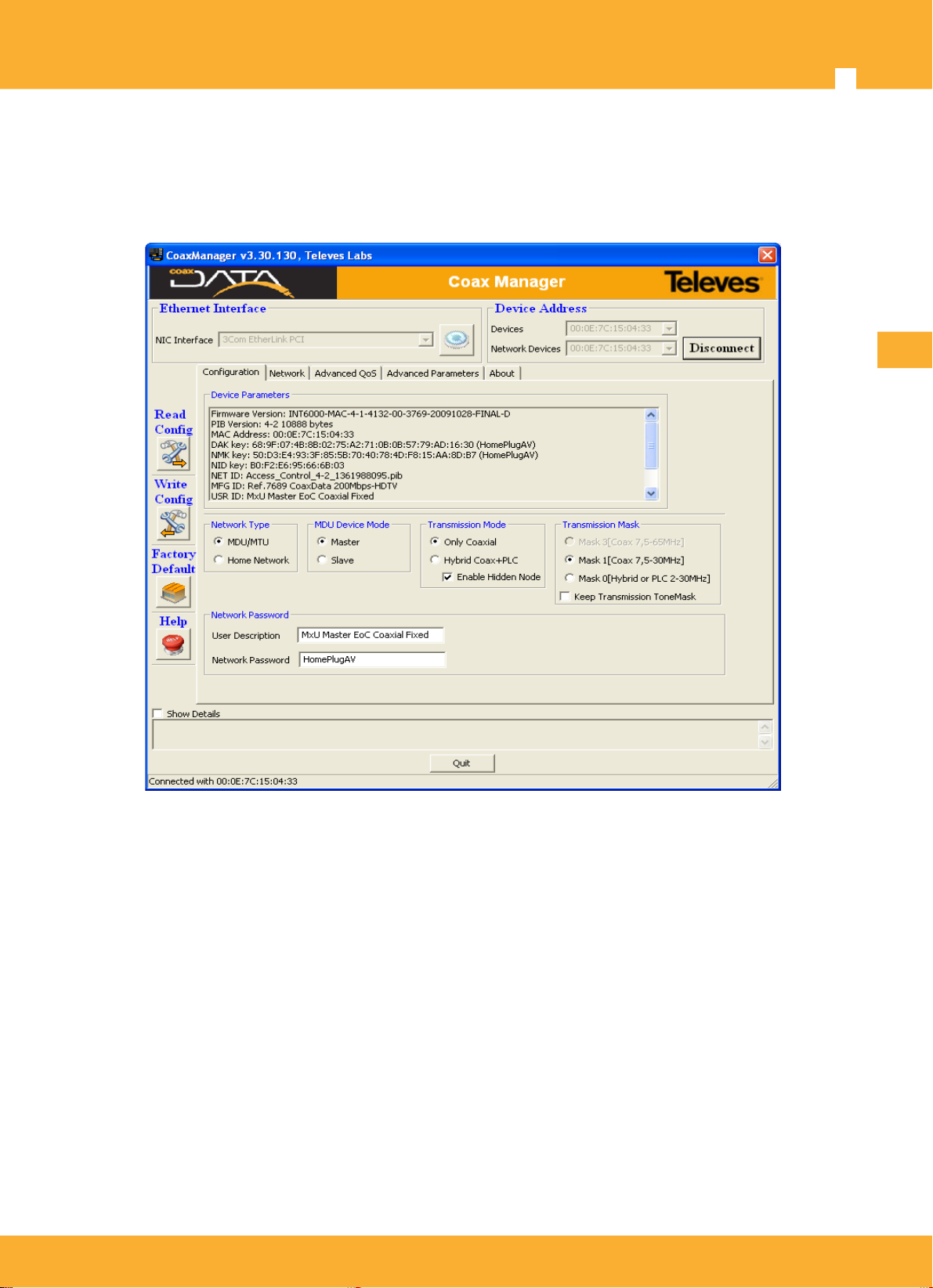
Operation mode setting can be performed through Configuration tab, where shows device info and
also those fields that configure device access mode, network password or transmission mask.
EN
Device Parameters displays information about device:
• Firmware Version: Version Info of Device Firmware.
• PIB Version: Device PIB Version (Parameters Information Block) . PIB stores user configuration
changes and contains firmware runtime parameters.
• MAC Address: Device MAC Address. All Televes MAC Address start with 00:0E:7C
hexadecimal values and are registered on IEEE.
• DAK key (Device Access key): Key established in the manufacturing process and determines
access to devices when it occurs remotely (via coaxial). Knowledge of this key is essential for
updating/configuring devices remotely, although default DAK key value is always the same, on
manufacturing proccess, simplifying devices configuration.
www.televes.es

Televes
• NMK key (Network Management Key): Key set by the user and allows creation of different
data networks named AVLN. This 128bit hexadecimal key, is generated based on the Network
Password field value using a hash algorithm. NMK key determines whether a slave can connect
to a master or not and only devices with the same NMK can be connected together.
• NET ID, MDF ID, USR ID: Description fields determining the network name, Televes product
description and user description, done by the installer. Installer can change descriptions that
make sense in the coaxial network as the location of the modem, its role in the network or who
is using it.
• MDU mode: Indicates whether MDU mode is active or not.
• CCo mode (Central coordinator): CCo is responsible for coordinating communications
between devices. In MDU, a CCO is always a master, in HomeNetworking is determined
randomly formed networks, not always the same, and all devices can communicate with each
other.
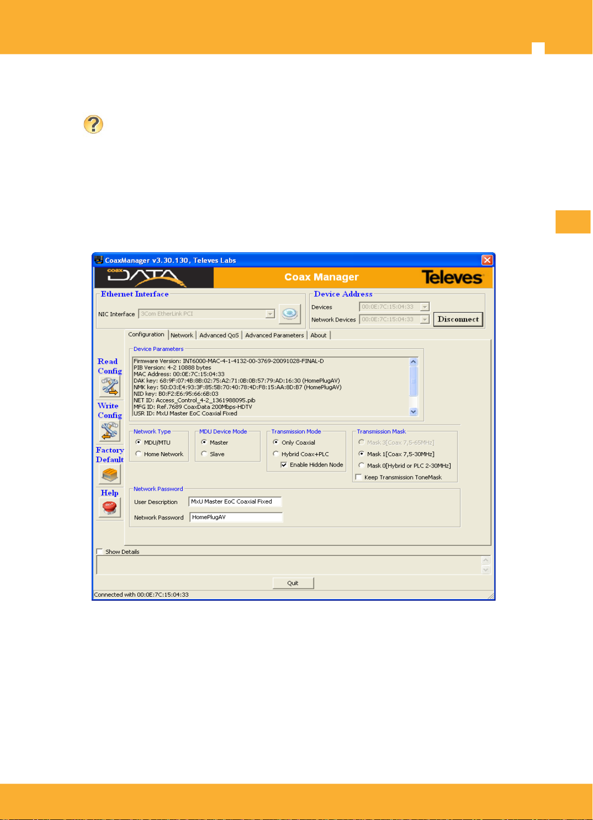
MDU Configuration
Sets operating mode of the device.
9
®
EN
Home Networking: This is default mode setting
at the factory and allows the creation of a local
area network where all devices communicate with
each other. These networks are usually created
when the modem is used to extend internet
services within a house. Default mode that is
retrieved using the Defaults button.
MDU/MTU (Multi-Dwelling/Multi-Tenant Unit).
This mode uses current coaxial network on a
building or house to communicate from the
headend with each of modems installed on
coaxial outlets, providing access to multiple
dwellings without can communicate with each
other. In this mode have two modes, master and
slave.
If you select MDU option is necessary to specify which mode you want:
• Master: CoaxDATA operate in master mode and is typically installed in the headend, as
described in CoaxDATA product manual. Master controls when the slaves can access the
medium synchronizing transmissions and avoiding slave conflicts.
• Slave: modem will be installed in a coaxial outlet, as indicated in CoaxDATA product manual.
www.televes.es

CoaxManager™ User Guide
Select Transmission medium
Sets device transmission medium
• Hybrid Coax+PLC: This option indicates that operation mode is hybrid, where devices
communicate via PLC and Coax. The medium swich on front of device must be on the left
and power LED is set to orange color.
• Only Coax: In this mode of operation only coaxial is used as communication medium. The
medium swich on front of device must be on the right and power LED is set to green color.
10
• Enable Hidden Node: This option changes medium access mechanism of the devices.
Typically medium access method is based on CSMA (carrier sense medium access) listening
and checking medium is avaliable. Devices access to medium when no one else is transmitting.
This mechanism, however, requires that all of the devices can listen all transmissions of other
devices connected to the network. Depending on the coaxial network in which the system is
implemented, there may not listen slaves of other slaves transmissions due to a high isolation of
distribution outlets (> 100dB) and CSMA access mechanism in not valid.
EN
Enable Hidden Node option replaces medium access contention for a token-based system, where
slaves transmit only when the master gives them permission. For this mechanism to work properly, all
devices on the network must have this feature enabled.
With this feature modems access to the medium only when they have permission to do so, providing
better performance in environments where the insulation between slaves is very high. Since the devices
have to get the token for access to the medium, there is a 20% reduction in the total thoughput system.
This feature is enabled by default when user select Coaxial Medum to transmit. Disable only when
isolation between slaves is a known low value.
www.televes.es

Televes
Transmission Mask
This option allows setting the transmission mask to use:
• Mask 0, Hybrid Mask: This mask transmission is set by default when it is being used in
HomeNetworking. Signal starts in very low frequency (2Mhz) to assure transmission on power
line network.
• Mask 1, Sólo Coaxial: This Transmission mask is used in Coaxial Only mode, the signal starts
at a higher frequency (7.5 MHz instead of 2Mhz) avoiding the possible degradation of the
communication by using very low frequencies (2 to 7.5 Mhz): noise produced by power
switching sources, ground earth on installation, etc...
This mask is used on coaxial transmission at CoaxDATA Ref.200Mbps ref.7689 and ref.768973.
It is similar to the Mask 3 and no spectral difference, only provided for compatibility between
different CoaxDATA 200Mbps and 1Gbps products and different firmware versions.
• Mask 3, Sólo Coaxial: Transmission mask used in Coaxial Only mode, the signal starts at a
higher frequency (7.5 MHz instead of 2Mhz) avoiding the possible degradation of the
communication by using very low frequencies (2 to 7.5 Mhz): noise produced by power
switching sources, ground earth on installation, etc...
This transmission mask is used by default on CoaxDATA 1Gpbs devices like refs 769201,
769202 and 769203.
11
®
EN
Frequencies Range used by different transmission masks depend on the product being used
CoaxDATA 200Mbps
Mask 0
Hybrid
2-30Mhz 7,5-30Mhz 7,5-30Mhz
Mask 1
Only Coax
Mask 3
Only Coax
Ref.7689, 768973
CoaxDATA 1Gbps
2-67,5Mhz 7,5-67,5Mhz 7,5-67,5Mhz
Ref.769201, 769202, 769203
Network Password, Create an AVLN Network
This option allows you to set the network key (NMK) devices. All devices that want to communicate
within the same network need the same key NMK. Network set up multiple devices with same key are
called AVLN (HomePlug AV Logical Networks) .
NMK is a 128-bit Hexadecimal value, in order to generate valid NMK in a easy way, Network Password
on CoaxManager provide a text passphrase, which through a hash algorithm, generate necessary
NMK. The passphrase must be entered without any spaces.
Default Network Password is “HomePlugAV” which generate NMK key 50:D3:E4:93:3
F:85:5B:70:40:78:4D:F8:15:AA:8D:B7(HomePlugAV).
Network key also defines various networks established in a coaxial network called
AVLN (Associated Logical Virtual Network). It is possible to set up four masters
simultaneously in a coaxial network.
If user enters a different network key that default, HomePlugAV, next time you connect to device for
safety CoaxManager prompted the introduction of it.
www.televes.es

CoaxManager™ User Guide
Be careful and don't forget the password to connect with devices later.
In case you have forgotten the password, you have a button on the front
of the device called Factory Defaults Button that allows the device
restored to factory settings and reset network key as the default key,
HomePlugAV.
12
EN
User Description
Description that user wants to assign to the device. Descriptions can be set to what makes sense for
the installation and the location of the modem, its role in the network or the user who is using it.
Writing Device Settings
Once the user has configured CoaxDATA modem with the appropriate values, Write Config Button
write configuration on device. Configuration is stored in a memory area dedicated to user settings.
If you have issues about setting up or want to delete, Press Factory Default Button to restore the device
to the factory, eliminating user settings.
When writing the configuration to a remote device connected through
the coaxial, be careful if you change the network key, Network
Password, since when change key, change network membership and can
not reconnect to device remotely.
By changing the network key loses connectivity via coaxial and
reconfigure device will have to do well locally, connecting in the place
where it is installed, or set as network key local device the same as the
remote device. The same also applies if you change the transmission
mask or MxU master/slave mode.
www.televes.es

Televes
13
Checking Devices Network
CoaxManager can check data network created with tab named Network that allows you to view the
network information associated with a device and other devices as part of the same AVLN (Associated
Logical Virtual Network), ie, the devices they have been programmed with the same Network
password.
®
EN
Device Info
Parameters shown in Device Info:
• MAC: MAC address of the device that we have connected.
• TEI (Terminal equipment identifier): Is an unique identifier of a device on a network. It can
accommodate values from 1 (master) to 253 (slaves) MxU mode, and up to 64 slaves on
HomeNetworking mode.
• Hosts Info: List of different users who have connected to the device from its Ethernet interface.
• Ethernet Link: Indicates if any of the two Ethernet interfaces of the device is connected. If is
On, this field indicates that the device has someone connected via Ethernet.
• Get Counters: This button allows access to the information packets transmitted by the device.
The counters displayed are those associated with the coaxial transmission protocol not
Ethernet packet count, so these counters are not suitable to measure the traffic sent by a user,
and only used for informative purposes.
www.televes.es

CoaxManager™ User Guide
14
CCO Info
Parameters shown in CCo Info:
• CCo MAC: MAC address of the device with CCo functions (Central Coordinator) on the
network. On MxU, displays MAC Address of network master.
• CCo TEI (Terminal equipment identifier): Is an unique identifier of a device on a network. It is
always 1
• NID (Network identifier): When a master proceeds to create new networks on coaxial data
generated Network identifiers value by a hash algorithm. In same network can coexists up to 4
masters with same Netwok Password, creating same AVLN, but with a different NID Identifier. A
slave may choose to connect to a master NID or with other, depending on channel conditions.
• SNID (Short Network identifier): Value derived from the NID but a single byte. This value is used
by slaves to uniquely identify the master who joined to form a network.
Network Topology
This section contains information related to network modems. When the application is connected to the
master shows the links established with the slaves.
EN
When device has link set but none devices connected to Ethernet ports show a MAC Bridge = FF: FF:
FF: FF: FF: FF and displays a estimate of the channel's bandwidth with three colours green, orange or
red.
When device have Ethernet hosts and really there is a flow of information between the master and a
slave, you will see information on the channel coding (Mbps) in the columns for TXCoded / Raw (Mbps)
and RXCoded / Raw (Mbps), which indicate rates maximum reached by the channel coding on each of
the links.
Attenuation conditions, channel noise or zero frequency response can alter the values obtained for
throughput. To make more intuitive analysis of the values in the application has chosen a range of
colors to indicate the status of the channel
Indicates that the link operates
at maximum rate
Indicates that the link operates
at medium rate
Indicates that the link operates
at poor rate
coaxDATA 200Mbps-HDTV (120Mbps<throughput<150Mps)
coaxDATA 1Gbps-HDTV (300Mbps<throughput<450Mps)
coaxDATA 200Mbps-HDTV (70Mbps<throughput<120Mps)
coaxDATA 1Gbps-HDTV (170Mbps<throughput<300Mps)
coaxDATA 200Mbps-HDTV (throughput<70Mps)
coaxDATA 1Gbps-HDTV (throughput<170Mps)
CoaxManager also provide data about the link tonemap (set of carriers with QAM 4096, QAM 1024,
QAM 256,..., QPSK) and transmission mask, which indicates whether the carriers are attenuated or
transmitting.
By clicking directly on the link you will get the following window with all the data on it.
This information allows to know in addition to providing the link information about frequencies where, by
excessive noise or channel attenuations, are decreased their rate tonemap and each of the carriers
contributing to the data stream.
www.televes.es

Televes
15
®
EN
• Source and Destination MAC: MAC Address of devices that MAC devices that make up the
link.
• TX Rate Coded/PHY y RX Rate Coded/PHY (Mbps): Estimated Channel rate, for both
transmission and reception.
• Avg.SNR: Average SNR estimation of received signal
• Avg.Attenuation: Average attenuation of the signal in the transmission network.
Generating traffic to verify network links
Some of the information associated with the devices are shown only in the event that there is effective
transmissions between two devices. If a device is not connected to any PC, STB or other devices,
Generate Traffic button allows virtual generation of traffic between connected device and remote
devices that are part of the network.
This feature is only available when connected locally to a device through an
Ethernet cable, but is not available when CoaxManager connect to a remote
device.
www.televes.es

CoaxManager™ User Guide
16
Once the traffic generated between all links, the application displays a message indicating packet
generation is over. With this option we can get an estimate of channel between devices without any
active hosts on devices, this is useful to check the links at the time of installation of apartment
buildings, hotels, etc. ..
The duration of this test depends on the number of devices that form
the data network.
Generating Reports for Checking Network State
application can generate reports containing all the information concerning the status of the network.
These reports allow you to export information generated by the application in PDF for later review.
Generate Report Button automatically generate the PDF report :
EN
www.televes.es

Once generated PDF report,
you can save a compressed
(tgz) that contains all the
information captured from the
network and can be analyzed
later.
Televes
17
®
EN
www.televes.es

CoaxManager™ User Guide
Setting QoS parameters (Advanced User)
This tab allows configuration of the QoS parameters of a device.
18
EN
CoaxDATA devices have various QoS mechanisms that allow prioritize traffic by type: either video,
voice or data. Each one of these traffic can have, depending on the installation requirements and
provide different mechanisms for ensuring priority.
You can set up to 4 priority levels, called CAP "Channel Access Priority": CAP3 (highest priority), CAP2,
CAP1 and CAP0 (lowest priority). Packets belonging to higher priority are transmitted first.
There are three mechanisms for priority setting. Are shown in order of
preference in the firmware.
- Default Priorities
- Mapping as 802.1p and / or cough
- QoS Rules (CoaxManagerPro Only)
Default Priorities
This section allows the assignment of priority levels based on packets by type. This assignment
overrides VLAN tag (802.1p) or IPv4 ToS (Type of Service) priority settings:
Unicast (default CAP1): sets the default priority for unicast packets without VLAN tag
transmitted between devices
IGMP (default CAP3): Permite asignar la prioridad de paquetes IGMP utilizados para gestionar
streams multicast.
www.televes.es

Televes
Multicast (default CAP1): Prioridad asignada a streams multicast que no son gestionados por
IGMP; es decir, aquellos streams multicast para los cuales no se han generados IGMP reports
ni existen IGMP queries que los gestionen.
Multicast gestionados por IGMP (default CAP3): Prioridad asignada a streams multicast que
han sido gestionados por los dispositivos mediante IGMP Snooping.
Priority Levels Assignment
Packets can be assigned to the desired priority level based on:
• VLAN 802.1P Priority: VLAN tags are small data field in 802.1 Ethernet packets and
determines or specifies the packet type in question. This tag is normally assigned at source or
swiches established by the network depending on the input port (or any other parameter:
multicast, UDP. Destination port, etc). You can set the "User Priority" Tag VLAN 802.1P priority
levels CAP0-CAP3.
19
®
EN
• IP Traffic Class: Priority based on ToS (Type of Service) of IP packets. RFC 1349 describes
this field and values like delay, rate optimization or reliability. You can assign one of four priority
levels CAP0-3 device according to the first 3 bits of the ToS field (ToS Precedence).
TTL - Time to Live
CoaxDATA devices allow you to specify a parameter called TTL (Time to Live) for each priority level,
CAP. This parameter indicates how long a packet can stay in the buffers (SDRAM) before exceeding
the maximum lifetime. Once established time is out packet is dropped.
The time a packet remains in the device buffers before transmission depends on network traffic
conditions, the number of modems that make up the network and its effective occupation, so that the
establishment of these values should be account the implementation and the estimated rate of service.
By example, this mechanism is often used in VoIP or Video packets where packet time on buffer is
excessive and can be discarded because elapsed time is too late at the receiver and is not necessary
for decoding.
TTL values for each priority queue and MME (Management Messages, which are used by the
www.televes.es

CoaxManager™ User Guide
application management like CoaxManager) can be set. The default values are set as follows:
• CAP0 traffic: 2000 msec (used for TCP data traffic)
• CAP1 traffic: 2000 msec (used for TCP data traffic)
• CAP2 traffic: 300 msec (used for UDP video/music traffic)
• CAP3 traffic: 300 msec (used for VoIP traffic)
• MME traffic: 300 msec (used for Management Messages)
20
It is recommended not to change TTL values unless you know exactly what
you are doing.
Buffer Allocation, Priority Thresholds
This option determines memory size (buffers) for each of the priorities. When buffers are full, packets
are dropped based on their priority.
Thresholds determining buffers available for each
priority.
Available buffers are managed in terms of a percentage
allocated to each CAP. When the percentage of
allocated buffers exceeded, lower priority packets are
discarded but higher priority is still admitted.
By enabling this option, the packages are stored waiting to be transmitted, but if at any time it exceeds
a certain percentage of occupancy, the packet is discarded leaving room for higher priority packets.
EN
example:
Suppose you have the following prioritization:
Assigned Percentage
Total Percentage
(accumulative)
CAP 0 and higher = 20%
CAP 1 and higher = 25%
CAP 2 and higher = 45%
CAP 3 = 10%
At any given time:
- If the total number of buffers used for transmission is less than 20% shall be
allowed traffic of all priorities (CAP 0 or better).
- If the total number of buffers used exceeds 45% shall be allowed only packages
or higher priority CAP1 (CAP1, CAP2 or CAP 3).
- If the number of occupied buffers is greater than 90% are permitted only packets
with higher priority than CAP 2, ..., and so on.
20 %
45 %
90 %
100 %
www.televes.es

Televes
This mechanism allows to safeguard the buffer system, preventing higher
priority packages run out space with lower priority waiting to be
transmitted.
It is necessary to take into account that if the thresholds for priority are
not activated, there will be a single buffer to store packets of all priorities,
so when buffer is full packets are discarded regardless of their priority. If
you want higher priority packets have a reserved space in the buffer,
enable this option.
21
®
Bandwidth Limit
The bandwidth limit can set a limit on the total transmitted/received data rate, regardless of the priority
assigned to them. This limit is activated only when operating mode is MDU. The minimum value is
64Kbps and maximum 16Mbps in increments of 64 Kbps.
Upstream Limit: Limits the traffic transmitted by a host device, ie , from host (Ethernet) to the
coaxial.
Downstream Limit: Limits the traffic received by the Ethernet hosts of device, ie , from the
traffic received by the coaxial towards hosts (Ethernet).
Bandwidth limit is a feature that can be used in MDU distributions where
the installer wishes to set a limit on the bandwidth used by users,
programming limit on slave modems. This option is ignored on Home
Networking mode.
Bandwidth limit overrides QoS priority. all packets are dropped if exceed
limit, regardless of its priority
Bandwidth Limit with QoS
EN
Bandwidth Limit allows operators/installers configure CoaxDATA™ products so that users can only use
a certain bandwidth that have hired. However, this functionality can not preserve established QoS
settings for data flows, ie, limit of bandwidth is for all traffic without distinguishing the priority of the
packets.
To ensure QoS parameters are preserved even if there is bandwidth limit on devices, a new option
named QoS For Bandwidth Limit is provided, which allows bandwidth limit setting considering QoS
for flows transmitted, thereby providing important quality of service for certain applications such as
video or voice transmission.
limits the bandwidth used by users, considering the priority of flows, so that the limit applies
taking into account packets priority and those lower priority flows are discarded first.
Limitation of bandwidth occurs in the internal switch of device, which provides two output
ethernet ports. Therefore only devices that have an internal switch allow you to implement
this functionality.
www.televes.es

CoaxManager™ User Guide
22
Following CoaxDATA™ devices support QoS For Bandwidth Limit
• Ref.7689 CoaxDATA™ 200Mbps-HDTV
• Ref.769201 CoaxDATA™ 1Gbps-HDTV
• Ref.769202 CoaxDATA™ 1Gbps-HDTV with SFP
Following CoaxDATA™ devices do not support QoS For Bandwidth Limit: Bandwidth Limit is applied to
all flows regardless their QoS:
• Ref.768973 CoaxDATA™ 200Mbps-HDTV 1xEth
• Ref.769203 CoaxDATA™ 1Gbps-HDTV 1XEth
EN
www.televes.es

Televes
23
Setting Advanced Configuration
Following options are available for advanced users with a basic knowledge of networking concepts,
configuring devices in a more specific way. If you do not understand any of the concepts presented, do
not worry probably not need to know.
Below is a screenshot of the application for advanced parameters:
®
EN
IGMP options
IGMP (Internet Group Management Protocol) is a protocol for managing multicast flows and define the
devices to receive multicast data stream (video, audio, etc. ..). IGMP may save bandwidth, indicating
devices want to receive a given flow preventing traffic reaches the devices are not interested in the
data stream.
CoaxManager provides options to define the behavior of the device on the IGMP protocol. The system
supports both IGMPv2 and IGMPv3.
IGMP defines a set of messages to set up multicast network:
www.televes.es

CoaxManager™ User Guide
24
• IGMP join: Message sent by a device or set-top box that wants to join a multicast group.
• IGMP leave: Message sent by a device or set-top box that wants to leave a multicast group.
• IGMP Querier (Only IGMPv3): IGMP querier is a IGMP function that imlements a Query
message (usually Multicast Routers and Switches) where the network periodically ask if anyone
is joined to a multicast group. Devices members of multicast channels respond with IGMP
message indicating which groups are connected. IGMP Querier can send request for all
multicast groups or requests for each managed multicast.
EN
To ensure membership of multicast channels and that information is as updated as possible, and thus
prevent a user leaves a channel waste bandwidth, in the IGMP protocol timers are defined:
• Group Specific Queries Timeout (Only IGMPv3): This timer expires after 260 seconds where
no IGMP Queries sent to a specific group that has been registered in the device. A registered
group is one in which there are set-top boxes that indicate their membership of a particular
group responding to IGMP queries that are sent periodically by the Multicast Router. If the timer
is disabled, once registered multicast flow will not be removed from the table even if no queries
made by the Multicast Router.
• All system Queries Timeout (Only IGMPv3): This timer expires after 260 seconds where no
IGMP Queries sent to all multicasts groups that has been registered in the device. If the timer is
disabled, no multicast flow will be removed from the table by expiration timer associated with All
System IGMP Query requests.
• Group Membership Timeout (Only IGMPv3): This timer controls the period that goes from the
transmission of a query to the STB and the lack of response. Delete a stream for which there
has been no reply from any STB. If the timer is deactivated the stream will remain active
indefinitely.
Normally when a router or switch has no response from a Set-Top Box after several attempts asking
about membership in a multicast channel, delete the device joining to the multicast stream, setting a
conservative procedure regarding use of bandwidth and causes the master stops transmitting these
streams to the coaxial network after expiration of timers.
www.televes.es

Televes
25
If you have not installed an IGMP Querier in video distribution, or do not want the streams are
eliminated after the expiration, disable timers through the checkboxes in the application.
No purpose of this manual is to define the IGMP protocol or the
elements that comprise it. For details refer to the standards defined in
this regard: RFC 1112, RFC 2236 IGMPv2 and RFC 3376 IGMPv3
It is recommended not disable timers unless the system do not support
IGMPv3 (only support the old IGMPv2). In practice, if disable timers
then when device does not indicate that leaves a channel (IGMP leave)
by switching channels or disconnected abruptly, he still remains
member of channel with the consequent consumption of bandwidth.
Additionally, you can configure a number of parameters associated with IGMP:
Forward Unknown/Unmanaged Streams: All multicast streams are transmitted from the
master to the slave even if no one registered in them. Since there is no list of registered devices
in each multicast, master uses a very conservative modulation which results in excessive
bandwidth consumption. This modulation is named ROBO (ROBust mOdulation) and transmits
a maximum of 5Mbps to all devices on netwok. It is not recommended to use this option
unless you really know what you are doing.
®
EN
IGMP Reports to Non-Querier Hosts: By default, IGMP reports only are sent to Ethernet ports
if IGMP Querier exists on network, ie, IGMP reports are sent to querier. When this option is
enabled allows resend all IGMP join/leaves to Ethernet ports even if IGMP Queriers are not
present (ie , Multicast routers or switches connected to the Master). This allows IGMP reports
are propagate to network even when no multicast IGMP Queriers exists, but STB periodically
send IGMP messages indicated their intention to belong to a specific multicast group.
Although it is possible to implement videostreaming systems that do not require the existence of IGMP
Queriers, Installer is recommended to implement an IGMP querier, with a multicast router or a switch,
so as to provide an automated management and that guarantees that the bandwidth is used only when
users actually want to use video services and releasing those resources when leaving a channel.
Number of Users per Slave
When coaxial data network is implemented in community facilities, is very useful to limit the number of
users for each slave, since customers in their homes can use more than one device. This also
increases engine performance of the system, since it limits the number of links in the system:
• MAC Address Limit: This option sets a limit on the number of hosts connected to MAC
Ethernet ports that a device supports. This option can be used by installers of hotels, buildings,
who want to limit the number of users who use the data service from the slaves and allows
control on the number of total users that will use the data network.
• Bridge Address Aging: Set the timer used to determine when an entry in the local table
(associated with Ethernet hosts) or a remote table (where hosts are picked from other devices
on the network) is invalid or has expired .
Network Mitigation
Normally in a network of one master and several slaves they transmit at maximum power in order to
ensure greater coverage and throughput. It is possible that in a coaxial network are installed two
different networks, with two masters and their slaves are poorly insulated from each other or the
insulation provided by the network is not sufficient and interference occurs between adjacent networks
www.televes.es

CoaxManager™ User Guide
26
EN
When several masters coming together or poorly insulated and we form two different networks have the
option to control the transmission power and reception sensitivity of the devices on a network to
mitigate the effect these have on a network transmissions next and viceversa . This is done by
detecting certain packages from nearby networks.
The mitigation Network provides an alternative to the diplexer filter installation for the isolation of data
networks. We recommend installation of those filters diplexers so as to isolate the different networks in
the coaxial data, see the product manual for more information.
If it is not possible to isolate the networks with filters diplexers, Mitigation Network option allow masters
from each of the networks controlling the transmission power of all the elements in order to mitigate the
effects that their transmissions have a close network . In the event that this option is not activated, the
transmissions of other nearby networks are regarded as transmit interference causing a decrease in the
transfer rate between the devices.
Do not use this option in case your installation scheme consists of the installation of multiple masters on
the same coaxial distribution (multiple AVLN) and not on separate segments (multiple dwellings)
Keep in mind that the mitigation process is reducing the transmission
power of the devices and their sensitivity with consequent loss rate and
coverage. This option allows both networks to obtain best rates provided
the coverage thereof is not excessive and a decrease in transmission
power will not cause a decrease in link quality.
This adjustment process uses an iterative algorithm can have a
convergence period of about 17min, so keep this in mind when you
restart the device. This period is so long due to the fact that the system
must distinguish between noise inherent and/or transients in the
transmission line network transmissions causing interference nearby
permanent.
www.televes.es

Factory Defaults Button
This option allows you to disable the front button that resets the device to factory settings.
Use is limited to cases where the installer wants
CoaxManager configuration not be deleted by the
client when press the button.
This option increases product security, when
disable factory button it is impossible to use it to
delete user settings when press.
Televes
27
®
EN
Although button is disabled, the Factory Default option on
CoaxManager through GUI interface is still running and
you can set the factory settings by cliking button on
application.
Advanced Power Management
This option enables the low power mode on the device, allowing greater energy efficiency. The low
power mode is activated when no device connected to the host, or when even if there is connection to
PC not transmit data over a long period.
The following table shows the energy savings achieved when activated low power mode
Power
CoaxDATA 200Mbps
(Watts)
Normal Working
Low Power Mode
4.5Watts 6Watts
1.8 Watts 1.8 Watts
This option is only available on HomeNetworking mode and firmware versions that support it. In MDU
mode this option is not available since some programs like AccessControl™/CoaxManager™ not
function correctly when trying to connect to a remote device.
Power
CoaxDATA 1Gbps
(Watts)
Advanced MME Features
Tab provides options that affect the management protocol that is used to configure the devices
CoaxManager named MMEs (Management Messages).
Enable VLAN Tag MMEs: This option enables use of VLAN tags for receiving and sending
messages on the device MMEs. Use this option when the operator has a specific VLAN for
network management, or when you simply want to use a different VLAN for management.
VLAN ID used in responses (MME Response) is the same as that used in the requests
(Requests MME). VLAN used on indication messages, messages that emits an informative
request (MME Indication), is set on VLAN ID field on GUI.
www.televes.es

CoaxManager™ User Guide
28
Block Slave MME: This feature prevents slave sent management requests (MME) to master
through coaxial network. It can be activated on slave or master. This option prevents it from the
master to slave CoaxManager can connect to and change its configuration, Increasing the
safety of the installation.
MMEs over Data: By default, MME messages are transmitted in most robust modulation
possible ROBO (Robust Modulation) to ensure coverage in network. This penalizes the system
bandwidth as the maximum ROBO mode rate is 5Mbps and intensive management protocol
penalizes the bandwidth for use by users. This option allows devices management messages
transmitted in the same channels used for data transmission saving bandwidth. Use this option
on systems where the channel established between master and slave has good quality.
EN
www.televes.es

 Loading...