

Teledyne 3020 Installation And Operation Manual

3020 Submerged Probe
Part #60-3403-061 of Assembly #60-3404-058
Copyright © 1990. All rights reserved, Teledyne Isco
Revision P, February 2012
Flow Transmitter
Installation and Operation Guide


Foreword
This instruction manual is designed to help you gain a thorough understanding of the
operation of the equipment. Teledyne Isco recommends that you read this manual
completely before placing the equipment in service.
Although Teledyne Isco designs reliability into all equipment, there is always the possibility of a malfunction. This manual may help in diagnosing and repairing the malfunction.
If the problem persists, call or e-mail the Teledyne Isco Technical Service Department
for assistance. Simple difficulties can often be diagnosed over the phone.
If it is necessary to return the equipment to the factory for service, please follow the
shipping instructions provided by the Customer Service Department, including the
use of the Return Authorization Number specified. Be sure to include a note
describing the malfunction. This will aid in the prompt repair and return of the
equipment.
Teledyne Isco welcomes suggestions that would improve the information presented in
this manual or enhance the operation of the equipment itself.
Teledyne Isco is continually improving its products and reserves the right to
change product specifications, replacement parts, schematics, and instructions without notice.
Customer Service
Phone: (800) 228-4373 (USA, Canada, Mexico)
Fax: (402) 465-3022
Email: IscoCSR@teledyne.com
Technical Support
Phone: (800) 775-2965 (Analytical)
Email: IscoService@teledyne.com
Return equipment to: 4700 Superior Street, Lincoln, NE 68504-1398
Other Correspondence
Mail to: P.O. Box 82531, Lincoln, NE 68501-2531
Email: IscoInfo@teledyne.com
Web site: www.isco.com
Contact Information
(402) 464-0231 (Outside North America)
(866) 298-6174 (Samplers and Flow Meters)
Revised March 17, 2009


3020 Flow Transmitter
Table of Contents
Section 1 Introduction
1.1 Manual Organization . . . . . . . . . . . . . . . . . . . . . . . . . . . . . . . . . . . . . . . . . . . . . . . . 1-1
1.2 Description. . . . . . . . . . . . . . . . . . . . . . . . . . . . . . . . . . . . . . . . . . . . . . . . . . . . . . . . . 1-1
1.3 Associated Equipment. . . . . . . . . . . . . . . . . . . . . . . . . . . . . . . . . . . . . . . . . . . . . . . . 1-2
1.4 The Submerged Probe. . . . . . . . . . . . . . . . . . . . . . . . . . . . . . . . . . . . . . . . . . . . . . . . 1-2
1.5 Labels. . . . . . . . . . . . . . . . . . . . . . . . . . . . . . . . . . . . . . . . . . . . . . . . . . . . . . . . . . . . . 1-3
1.6 Controls, Indicators, and Terminal Blocks . . . . . . . . . . . . . . . . . . . . . . . . . . . . . . . 1-4
1.7 Technical Specifications . . . . . . . . . . . . . . . . . . . . . . . . . . . . . . . . . . . . . . . . . . . . . . 1-6
Section 2 Operation and Programming
2.1 Theory of Operation . . . . . . . . . . . . . . . . . . . . . . . . . . . . . . . . . . . . . . . . . . . . . . . . . 2-1
2.1.1 3020 Transmitter . . . . . . . . . . . . . . . . . . . . . . . . . . . . . . . . . . . . . . . . . . . . . . 2-1
2.1.2 The Submerged Probe . . . . . . . . . . . . . . . . . . . . . . . . . . . . . . . . . . . . . . . . . . 2-1
2.1.3 Transducer Operation . . . . . . . . . . . . . . . . . . . . . . . . . . . . . . . . . . . . . . . . . . 2-2
2.1.4 Amplifier . . . . . . . . . . . . . . . . . . . . . . . . . . . . . . . . . . . . . . . . . . . . . . . . . . . . 2-2
2.2 Controls and Indicators . . . . . . . . . . . . . . . . . . . . . . . . . . . . . . . . . . . . . . . . . . . . . . 2-2
2.2.1 Keypad Layout and Functions . . . . . . . . . . . . . . . . . . . . . . . . . . . . . . . . . . . 2-2
2.2.2 Display . . . . . . . . . . . . . . . . . . . . . . . . . . . . . . . . . . . . . . . . . . . . . . . . . . . . . . 2-3
2.2.3 Power Failures . . . . . . . . . . . . . . . . . . . . . . . . . . . . . . . . . . . . . . . . . . . . . . . . 2-3
2.3 Programming. . . . . . . . . . . . . . . . . . . . . . . . . . . . . . . . . . . . . . . . . . . . . . . . . . . . . . . 2-3
2.3.1 Programming Overview . . . . . . . . . . . . . . . . . . . . . . . . . . . . . . . . . . . . . . . . . 2-3
2.3.2 List of Program Steps . . . . . . . . . . . . . . . . . . . . . . . . . . . . . . . . . . . . . . . . . . 2-6
2.3.3 Description of Program Steps . . . . . . . . . . . . . . . . . . . . . . . . . . . . . . . . . . . . 2-7
2.3.4 Equations Used in Flow Conversion . . . . . . . . . . . . . . . . . . . . . . . . . . . . . . 2-11
2.3.5 Default Program . . . . . . . . . . . . . . . . . . . . . . . . . . . . . . . . . . . . . . . . . . . . . 2-11
2.4 Programming Examples . . . . . . . . . . . . . . . . . . . . . . . . . . . . . . . . . . . . . . . . . . . . . 2-13
2.4.1 Programming for a Parshall Flume . . . . . . . . . . . . . . . . . . . . . . . . . . . . . . 2-13
2.4.2 Programming for a Cipolletti Weir . . . . . . . . . . . . . . . . . . . . . . . . . . . . . . . 2-15
2.4.3 Programming with the Equation (Device #34) . . . . . . . . . . . . . . . . . . . . . . 2-19
2.4.4 Programming Example Using an Equation . . . . . . . . . . . . . . . . . . . . . . . . 2-20
2.4.5 Rectangular Weirs with End Contractions . . . . . . . . . . . . . . . . . . . . . . . . 2-23
2.4.6 Programming Example for a Rectangular Weir with End Contractions . 2-25
Section 3 Installation
3.1 General Comments on Installation . . . . . . . . . . . . . . . . . . . . . . . . . . . . . . . . . . . . . 3-1
3.1.1 Avoid Possibility of Submersion and Installation in Unsecured Locations 3-1
3.1.2 Location of the Flow Transmitter . . . . . . . . . . . . . . . . . . . . . . . . . . . . . . . . . 3-2
3.1.3 Portable Operation . . . . . . . . . . . . . . . . . . . . . . . . . . . . . . . . . . . . . . . . . . . . 3-2
3.2 General Wiring Comments . . . . . . . . . . . . . . . . . . . . . . . . . . . . . . . . . . . . . . . . . . . . 3-2
3.2.1 Mounting and Wiring . . . . . . . . . . . . . . . . . . . . . . . . . . . . . . . . . . . . . . . . . . 3-2
3.2.2 Stahlin Fittings . . . . . . . . . . . . . . . . . . . . . . . . . . . . . . . . . . . . . . . . . . . . . . . 3-3
3.2.3 Connection to a Power Source . . . . . . . . . . . . . . . . . . . . . . . . . . . . . . . . . . . . 3-3
3.2.4 Voltage Selector Switch . . . . . . . . . . . . . . . . . . . . . . . . . . . . . . . . . . . . . . . . . 3-4
3.2.5 Wiring the Submerged Probe . . . . . . . . . . . . . . . . . . . . . . . . . . . . . . . . . . . . 3-4
3.2.6 Distances Up to 75 Feet . . . . . . . . . . . . . . . . . . . . . . . . . . . . . . . . . . . . . . . . 3-5
3.3 Using the Quick-Disconnect Box . . . . . . . . . . . . . . . . . . . . . . . . . . . . . . . . . . . . . . . 3-6
i

3020 Flow Transmitter
Table of Contents
3.3.1 Reference Port . . . . . . . . . . . . . . . . . . . . . . . . . . . . . . . . . . . . . . . . . . . . . . . . 3-6
3.3.2 Mounting the Quick-Disconnect Box . . . . . . . . . . . . . . . . . . . . . . . . . . . . . . 3-6
3.3.3 Preparing Shielded Cable . . . . . . . . . . . . . . . . . . . . . . . . . . . . . . . . . . . . . . . 3-7
3.3.4 Connecting the Level Sensor Cable to the QD Box . . . . . . . . . . . . . . . . . . . 3-7
3.3.5 Connecting the Cable from the QD Box to the 3020 . . . . . . . . . . . . . . . . . . 3-7
3.4 Connection to a Sampler. . . . . . . . . . . . . . . . . . . . . . . . . . . . . . . . . . . . . . . . . . . . . . 3-8
3.4.1 Sampler Located Within 22 Feet . . . . . . . . . . . . . . . . . . . . . . . . . . . . . . . . . 3-8
3.4.2 Sampler Located Over 22 Feet . . . . . . . . . . . . . . . . . . . . . . . . . . . . . . . . . . . 3-8
3.4.3 Connection to a Non-Isco Sampler . . . . . . . . . . . . . . . . . . . . . . . . . . . . . . . . 3-8
3.5 Connection to Other Equipment. . . . . . . . . . . . . . . . . . . . . . . . . . . . . . . . . . . . . . . . 3-9
3.6 Safety Considerations . . . . . . . . . . . . . . . . . . . . . . . . . . . . . . . . . . . . . . . . . . . . . . . . 3-9
3.7 Installing the Submerged Probe. . . . . . . . . . . . . . . . . . . . . . . . . . . . . . . . . . . . . . . . 3-9
3.8 General Mounting Considerations . . . . . . . . . . . . . . . . . . . . . . . . . . . . . . . . . . . . . . 3-9
3.8.1 Functionality Under Solids . . . . . . . . . . . . . . . . . . . . . . . . . . . . . . . . . . . . . 3-10
3.8.2 Minimum Reliable Detection Level . . . . . . . . . . . . . . . . . . . . . . . . . . . . . . 3-11
3.9 Submerged Probe Nose Sections . . . . . . . . . . . . . . . . . . . . . . . . . . . . . . . . . . . . . . 3-11
3.9.1 Attaching the Nose Section . . . . . . . . . . . . . . . . . . . . . . . . . . . . . . . . . . . . . 3-12
3.10 Circular Channels . . . . . . . . . . . . . . . . . . . . . . . . . . . . . . . . . . . . . . . . . . . . . . . . . 3-12
3.10.1 Spring Rings . . . . . . . . . . . . . . . . . . . . . . . . . . . . . . . . . . . . . . . . . . . . . . . . 3-12
3.10.2 Scissors Rings . . . . . . . . . . . . . . . . . . . . . . . . . . . . . . . . . . . . . . . . . . . . . . 3-15
3.11 Other Mounting Techniques. . . . . . . . . . . . . . . . . . . . . . . . . . . . . . . . . . . . . . . . . 3-16
3.11.1 Rectangular and Trapezoidal Channels . . . . . . . . . . . . . . . . . . . . . . . . . . 3-16
3.11.2 Stilling Wells or Streams with Very Low Velocity . . . . . . . . . . . . . . . . . . 3-17
3.11.3 Securing Probe with a Weighted Plate . . . . . . . . . . . . . . . . . . . . . . . . . . . 3-17
3.11.4 Weirs and Flumes . . . . . . . . . . . . . . . . . . . . . . . . . . . . . . . . . . . . . . . . . . . 3-17
3.12 Completing the Probe Installation . . . . . . . . . . . . . . . . . . . . . . . . . . . . . . . . . . . . 3-19
Section 4 Options and Accessories
4.1 High-Low Alarm Relay Box . . . . . . . . . . . . . . . . . . . . . . . . . . . . . . . . . . . . . . . . . . . 4-1
4.1.1 Setting the Limit Switches . . . . . . . . . . . . . . . . . . . . . . . . . . . . . . . . . . . . . . 4-2
4.1.2 Installation of the Alarm Box . . . . . . . . . . . . . . . . . . . . . . . . . . . . . . . . . . . . 4-2
4.1.3 Wiring the Alarm Box . . . . . . . . . . . . . . . . . . . . . . . . . . . . . . . . . . . . . . . . . . 4-3
4.2 Connection to External Serial Devices. . . . . . . . . . . . . . . . . . . . . . . . . . . . . . . . . . . 4-4
4.3 Remote Totalizer . . . . . . . . . . . . . . . . . . . . . . . . . . . . . . . . . . . . . . . . . . . . . . . . . . . . 4-5
4.3.1 Wiring the Remote Totalizer . . . . . . . . . . . . . . . . . . . . . . . . . . . . . . . . . . . . . 4-5
4.4 Extension Cables for the Sensor. . . . . . . . . . . . . . . . . . . . . . . . . . . . . . . . . . . . . . . . 4-6
4.5 Quick-Disconnect Box . . . . . . . . . . . . . . . . . . . . . . . . . . . . . . . . . . . . . . . . . . . . . . . . 4-6
4.6 Model 2410 Circular Chart Recorder . . . . . . . . . . . . . . . . . . . . . . . . . . . . . . . . . . . . 4-6
4.6.1 Wiring the 2410 Recorder . . . . . . . . . . . . . . . . . . . . . . . . . . . . . . . . . . . . . . . 4-6
Section 5 Maintenance and Troubleshooting
5.1 Care of the Flow Transmitter Case . . . . . . . . . . . . . . . . . . . . . . . . . . . . . . . . . . . . . 5-1
5.1.1 Case Seal . . . . . . . . . . . . . . . . . . . . . . . . . . . . . . . . . . . . . . . . . . . . . . . . . . . . 5-1
5.1.2 Preventing Moisture Damage . . . . . . . . . . . . . . . . . . . . . . . . . . . . . . . . . . . . 5-1
5.2 Regenerating the Desiccant Cartridge. . . . . . . . . . . . . . . . . . . . . . . . . . . . . . . . . . . 5-2
5.2.1 Determining Condition of Desiccant . . . . . . . . . . . . . . . . . . . . . . . . . . . . . . . 5-2
5.2.2 Identify Desiccant . . . . . . . . . . . . . . . . . . . . . . . . . . . . . . . . . . . . . . . . . . . . . 5-2
5.2.3 Regeneration Procedure . . . . . . . . . . . . . . . . . . . . . . . . . . . . . . . . . . . . . . . . 5-2
5.3 Care of the Submerged Probe and Cables . . . . . . . . . . . . . . . . . . . . . . . . . . . . . . . . 5-3
5.3.1 Low Maintenance . . . . . . . . . . . . . . . . . . . . . . . . . . . . . . . . . . . . . . . . . . . . . . 5-4
5.3.2 Cleaning the Submerged Probe Without Disassembly . . . . . . . . . . . . . . . . 5-4
5.3.3 Disassembling the Probe for Cleaning . . . . . . . . . . . . . . . . . . . . . . . . . . . . . 5-4
5.3.4 Cable Inspection . . . . . . . . . . . . . . . . . . . . . . . . . . . . . . . . . . . . . . . . . . . . . . 5-5
5.4 Mechanical and Electrical Components. . . . . . . . . . . . . . . . . . . . . . . . . . . . . . . . . . 5-6
5.4.1 Accessing the Terminal PCB . . . . . . . . . . . . . . . . . . . . . . . . . . . . . . . . . . . . . 5-6
5.4.2 Accessing the Flow Transmitter PCB . . . . . . . . . . . . . . . . . . . . . . . . . . . . . . 5-6
ii

3020 Flow Transmitter
Table of Contents
5.4.3 Fuse Replacement . . . . . . . . . . . . . . . . . . . . . . . . . . . . . . . . . . . . . . . . . . . . . 5-8
5.5 Display Warnings . . . . . . . . . . . . . . . . . . . . . . . . . . . . . . . . . . . . . . . . . . . . . . . . . . . 5-8
5.5.1 Software Reset . . . . . . . . . . . . . . . . . . . . . . . . . . . . . . . . . . . . . . . . . . . . . . . . 5-8
5.6 Hints on Troubleshooting . . . . . . . . . . . . . . . . . . . . . . . . . . . . . . . . . . . . . . . . . . . . . 5-8
5.7 If Serious Problems Occur . . . . . . . . . . . . . . . . . . . . . . . . . . . . . . . . . . . . . . . . . . . . 5-9
5.7.1 Preliminary Troubleshooting Steps . . . . . . . . . . . . . . . . . . . . . . . . . . . . . . . 5-9
5.7.2 Precautions for Servicing AC-Powered Equipment . . . . . . . . . . . . . . . . . . 5-10
5.7.3 Precautions for Servicing CMOS Circuitry . . . . . . . . . . . . . . . . . . . . . . . . 5-11
5.7.4 Call for Assistance . . . . . . . . . . . . . . . . . . . . . . . . . . . . . . . . . . . . . . . . . . . . 5-12
5.8 Circuit Boards . . . . . . . . . . . . . . . . . . . . . . . . . . . . . . . . . . . . . . . . . . . . . . . . . . . . . 5-13
5.8.1 Terminal Board . . . . . . . . . . . . . . . . . . . . . . . . . . . . . . . . . . . . . . . . . . . . . . 5-13
5.8.2 CPU Board . . . . . . . . . . . . . . . . . . . . . . . . . . . . . . . . . . . . . . . . . . . . . . . . . . 5-13
Appendix A Replacement Parts and Accessories
A.1 Replacement Parts List . . . . . . . . . . . . . . . . . . . . . . . . . . . . . . . . . . . . . . . . . . . . . . A-1
A.2 Accessories and Spare Parts . . . . . . . . . . . . . . . . . . . . . . . . . . . . . . . . . . . . . . . . . . A-5
Appendix B Programming Worksheets
Appendix C General Safety Procedures
C.1 Practical Safety Precautions . . . . . . . . . . . . . . . . . . . . . . . . . . . . . . . . . . . . . . . . . . C-1
C.2 Lethal Atmospheres in Sewers . . . . . . . . . . . . . . . . . . . . . . . . . . . . . . . . . . . . . . . . C-4
C.3 Hazardous Gases . . . . . . . . . . . . . . . . . . . . . . . . . . . . . . . . . . . . . . . . . . . . . . . . . . . C-6
Appendix D Material Safety Data Sheets
D.1 Overview . . . . . . . . . . . . . . . . . . . . . . . . . . . . . . . . . . . . . . . . . . . . . . . . . . . . . . . . . . D-1
List of Figures
1-1 3020 Flow Transmitter . . . . . . . . . . . . . . . . . . . . . . . . . . . . . . . . . . . . . . . . . . . . . . 1-1
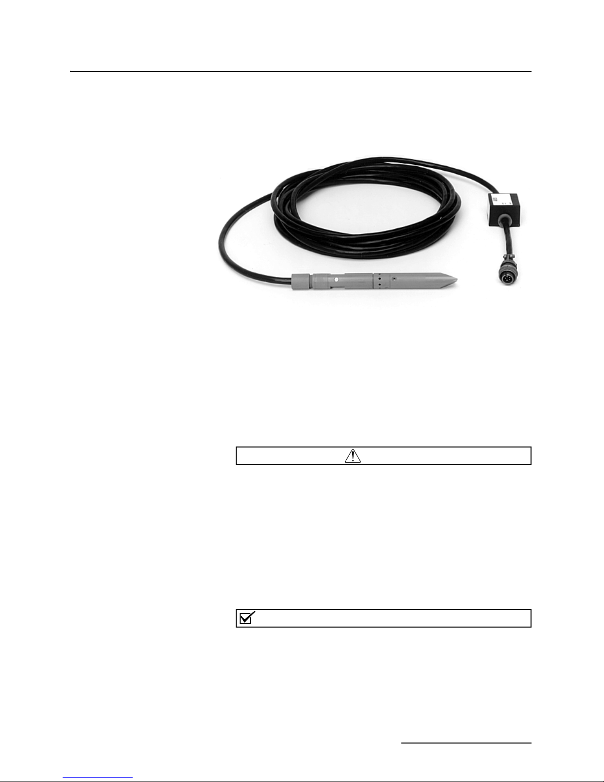
1-2 Submerged Probe Level Sensor (shown with standard tip) . . . . . . . . . . . . . . . . . . 1-3
1-3 3020 Control Panel . . . . . . . . . . . . . . . . . . . . . . . . . . . . . . . . . . . . . . . . . . . . . . . . . . 1-4
1-4 3020 Interior, Terminal Blocks . . . . . . . . . . . . . . . . . . . . . . . . . . . . . . . . . . . . . . . . 1-5
2-1 Simplified Flowchart Programming Flowchart for the 3020 . . . . . . . . . . . . . . . . . 2-5
3-1 View of Case Latch, Showing Lock Shackle . . . . . . . . . . . . . . . . . . . . . . . . . . . . . . 3-1
3-2 Stahlin Fittings (Compression Bushings) . . . . . . . . . . . . . . . . . . . . . . . . . . . . . . . . 3-3
3-3 Quick-Disconnect Box (cover removed) . . . . . . . . . . . . . . . . . . . . . . . . . . . . . . . . . . 3-5
3-4 Submerged Probe Dimensions . . . . . . . . . . . . . . . . . . . . . . . . . . . . . . . . . . . . . . . . 3-10
3-5 Alignment of Grounding Point . . . . . . . . . . . . . . . . . . . . . . . . . . . . . . . . . . . . . . . 3-12
3-6 Sensor Installed on a Spring Ring . . . . . . . . . . . . . . . . . . . . . . . . . . . . . . . . . . . . . 3-13
3-7 Spring Ring Preparation . . . . . . . . . . . . . . . . . . . . . . . . . . . . . . . . . . . . . . . . . . . . 3-14
3-8 Mounting Ring in a Round Pipe . . . . . . . . . . . . . . . . . . . . . . . . . . . . . . . . . . . . . . 3-14
3-9 Universal Mounting Ring Adjustment . . . . . . . . . . . . . . . . . . . . . . . . . . . . . . . . . 3-16
3-10 Isco Rectangular Mounting Plate . . . . . . . . . . . . . . . . . . . . . . . . . . . . . . . . . . . . 3-16
3-11 Typical Primary Device Installations . . . . . . . . . . . . . . . . . . . . . . . . . . . . . . . . . 3-18
4-1 High-Low Alarm Relay Box (cover removed) . . . . . . . . . . . . . . . . . . . . . . . . . . . . . 4-2
4-2 Interconnection of 3020 and Alarm Boxe(s) . . . . . . . . . . . . . . . . . . . . . . . . . . . . . . 4-4
4-3 Remote Totalizer . . . . . . . . . . . . . . . . . . . . . . . . . . . . . . . . . . . . . . . . . . . . . . . . . . . 4-5
5-1 Warning Disk Inside Probe . . . . . . . . . . . . . . . . . . . . . . . . . . . . . . . . . . . . . . . . . . . 5-5
5-2 Alignment of Grounding Point . . . . . . . . . . . . . . . . . . . . . . . . . . . . . . . . . . . . . . . . 5-5
5-3 Aluminum Cover and Interconnect Cables . . . . . . . . . . . . . . . . . . . . . . . . . . . . . . . 5-7
5-4 Circuit Board with Aluminum Cover Removed . . . . . . . . . . . . . . . . . . . . . . . . . . . 5-7
5-5 Component Layout of the CPU PCB . . . . . . . . . . . . . . . . . . . . . . . . . . . . . . . . . . . 5-14
iii

3020 Flow Transmitter
Table of Contents
List of Tables
5-6 Component Layout of the Terminal Board . . . . . . . . . . . . . . . . . . . . . . . . . . . . . . 5-15
1-1 3020 Controls, Indicators, and Terminal Blocks . . . . . . . . . . . . . . . . . . . . . . . . . . 1-5
1-2 3020 Flow Transmitter Technical Specifications . . . . . . . . . . . . . . . . . . . . . . . . . . 1-6
1-3 3222 Submerged Probe Technical Specifications . . . . . . . . . . . . . . . . . . . . . . . . . . 1-7
2-1 Equations Used in the 3020 . . . . . . . . . . . . . . . . . . . . . . . . . . . . . . . . . . . . . . . . . . 2-12
2-2 Values of N1 for Flow Rate in CFS . . . . . . . . . . . . . . . . . . . . . . . . . . . . . . . . . . . . 2-24
2-3 Values of N2 for Flow Rate in CFS . . . . . . . . . . . . . . . . . . . . . . . . . . . . . . . . . . . . 2-25
3-1 Locating the Head-Measuring Point . . . . . . . . . . . . . . . . . . . . . . . . . . . . . . . . . . . 3-17
4-1 3000 Series Wiring Instructions . . . . . . . . . . . . . . . . . . . . . . . . . . . . . . . . . . . . . . . 4-3
C-1 Hazardous Gases . . . . . . . . . . . . . . . . . . . . . . . . . . . . . . . . . . . . . . . . . . . . . . . . . . . C-6
iv

3020 Flow Transmitter
Section 1 Introduction
The first section of the 3020 instruction manual provides a
general introduction to the flow meter. It includes a brief discussion of the organization of the manual, an overall description
of the flow transmitter, and technical specifications.
1.1 Manual Organization The purpose of this manual is to provide the user with the infor-
mation necessary to operate, maintain, and service the 3020 Submerged Probe Flow Transmitter. To accomplish this, the manual
is organized into five sections. The first section is a general introduction to the flow transmitter. The second section contains
information on operation, programming the flow transmitter,
and operating examples. The third section provides installation
details. The fourth section describes available options and their
uses. The fifth section contains information on routine maintenance and servicing to assist the user in correcting problems that
may occur.
1.2 Description The 3020, shown in Figure 1-1, uses a submerged probe for level
measurement. The flow transmitter will normally be used with
some type of primary measuring device to measure flow in an
open channel. The 3020 uses level-to-flow rate conversions
derived from stored equations, which cover the vast majority of
open channel flow measurement situations. Also, the user may
enter the coefficients and powers of the flow equation. However,
most standard weirs and flumes are accommodated without the
need for this equation.
Figure 1-1 3020 Flow Transmitter
1-1

3020 Flow Transmitter
Section 1 Introduction
Programming the 3020 is done in two ways:
• Select the number of a choice listed on the flow transmitter front panel label and enter that number on the
keypad
• Enter a numeric value for steps requiring a value be
selected from a given range.
A six-digit LCD (Liquid Crystal Display) prompts the user
through setup, displays the choice for the current programming
step, and displays level and flow rate.
1.3 Associated Equipment The 3020 Flow Transmitter may be used with the following
equipment:
Interfacing
• 3700 and 6700 Series Portable and Refrigerated
Samplers
• GLS Compact Portable Sampler
• Glacier Refrigerated Compact Sampler
• 2410 Circular Chart Recorder
Optional Accessories
• Resettable 7-digit mechanical flow totalizer. (A
non-resettable flow totalizer is a standard feature of the
3020.)
• High-Low Alarm Relay Box
• Extension Cables for the submerged probe in lengths of
25 and 50 feet. (7,6-15,2 m)
• Quick-Disconnect Box
Allows probe installation up to 1000 feet (304,8 m) from
flow transmitter.
• Expansion rings and extension plates for mounting
probe
• Remote Totalizer
• Flow Transmitter-to-Sampler Connect Cable
1.4 The Submerged Probe The submerged probe, used by the 3020 Flow Transmitter as a
1-2
level sensor, is shown in Figure 1-2, and is mounted in the flow
stream. It measures liquid level by sensing changes in hydrostatic pressure as level increases or decreases above it. The submerged probe consists of a differential IC (integrated circuit)
pressure transducer mounted inside the probe assembly and a
shielded cable, which connects the submerged probe to an encapsulated electronics package containing an amplifier. The probe
body contains several ports which carry the hydrostatic pressure
of the flow stream directly to the transducer surface.
The cable contains not only the power and signal wires, but also
a hollow vent tube which serves to reference the differential port
of the pressure transducer to atmospheric pressure. A ground
wire in the cable keeps the flow transmitter ground and the
grounding point of the submerged probe at the same electric
CAUTION
Note
potential. Circuitry inside the 3020 converts pressure changes
sensed by the submerged probe into level and flow rate.
Figure 1-2 Submerged Probe Level Sensor (shown with standard tip)
3020 Flow Transmitter
Section 1 Introduction
1.5 Labels Adhesive labels are provided with the 3020 to allow the display
and the mechanical totalizer to express values which are greater
than the number of digits available in the unit. Where extremely
large flow volumes are involved, trailing zeroes may be added to
the display to make more meaningful numbers. Labels for units
of measure are also provided to serve as a visual reminder for
what units of measure the 3020 was programmed.
If the submerged probe is disassembled for cleaning, do not
touch the exposed stainless steel diaphragm inside the probe
with either fingers or instruments. The transducer, mounted
behind the diaphragm in silicone oil, is fragile. The diaphragm
is made from very thin material (0.003” thick). Deforming it
even slightly may cause a permanent offset to be placed on
the transducer, or may damage or break the chip bonding
wires, ruining the transducer. Flush the stainless steel diaphragm with gently running water only.
Various accessories for use with the 3020 Flow Transmitter,
such as connect cables, etc., are mentioned throughout this
manual. The part numbers for these items are listed on an
Accessory Parts List, which will be found at the back of the
manual. Part numbers for other equipment may be obtained
from the factory.
1-3
3020 Flow Transmitter
Section 1 Introduction
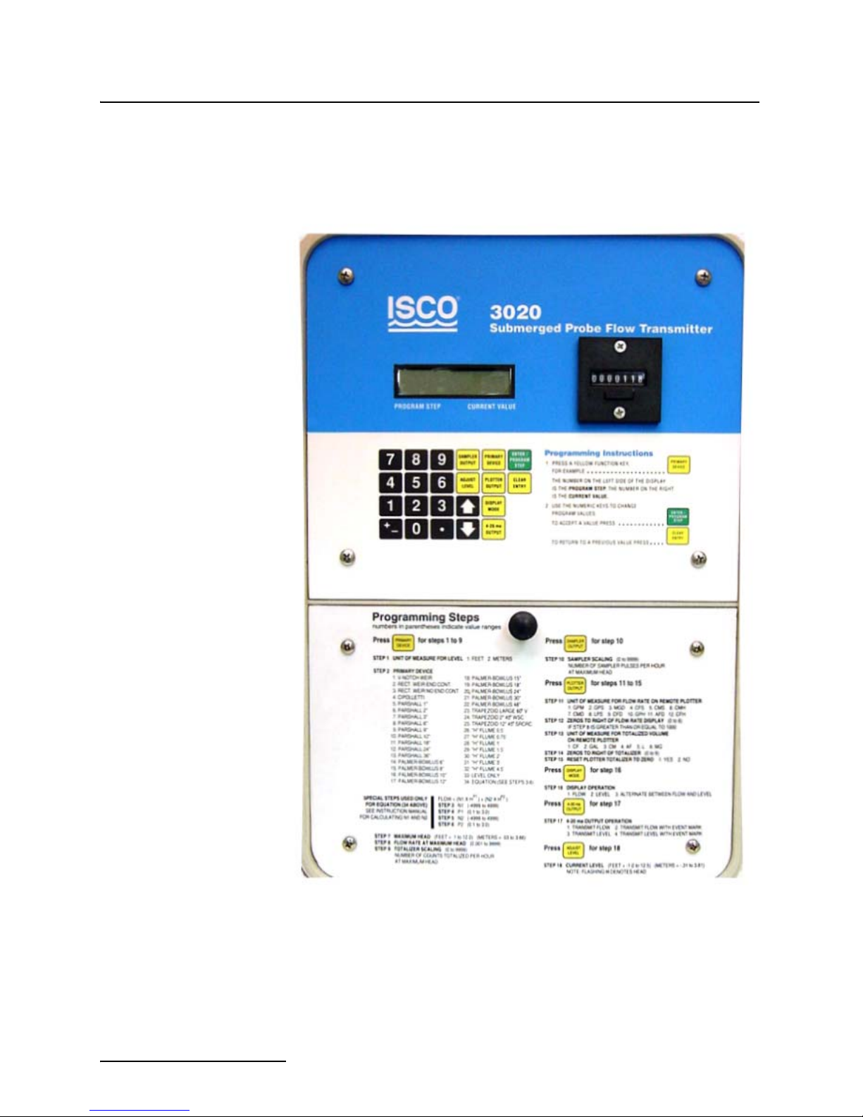
1.6 Controls, Indicators,
and Terminal Blocks
The controls, indicators, and terminal blocks of the 3020 Flow
Transmitter are listed in Table 1-1, and their functions are
briefly described. Refer to Figure 1-3 for a view of the controls
and indicators, and Figure 1-4 for a view of the connectors.
Figure 1-3 3020 Control Panel
1-4

3020 Flow Transmitter
TS1
TS2
TS3
Fuse
F1
Section 1 Introduction
Figure 1-4 3020 Interior, Terminal Blocks
Table 1-1 3020 Controls, Indicators, and Terminal Blocks
Controls Function
Keypad 22-Key, 6-column matrix. User programs flow
Indicators Function
Display 6-digit, 7-segment liquid crystal display
Terminal Blocks Type Function
Power 3 #8 screws on Block TS1
4-20 mA Output 2 #6 Screws on Block TS2
Remote Totalizer 2 #6 screws on Block TS2
Large Terminals 1, 2, and 3
Terminals 4 and 5
Terminals 6 and 7
transmitter through series of keystrokes
prompted by messages on the display.
(LCD). Prompts user through program setup;
displays current menu selections, displays
level.
Connects 120/240 VAC power to flow transmitter. #1 = Hot. #2 = Ground. #3 = Neutral.
Provides standard 4-20 mA current loop output (variable with level or flow rate) to be
used to control compatible equipment such
as a chart recorder or a chlorinator.
Connects flow transmitter to external
mechanical remote totalizer.
1-5

3020 Flow Transmitter
Section 1 Introduction
Table 1-1 3020 Controls, Indicators, and Terminal Blocks (Continued)
2312 Interface 3 #6 screws on Block TS2
Terminals 8 (data), 9 (+), and 10(-)
Bottle Number (BLT) 2 #6 screws on Block TS2
Terminals 11 (bottle #) and 12 (common)
Event Mark 2 #6 screws on Block TS 2
Terminal 13: +12 VDC
Terminal 14: Event Mark
Sampler Output 2 #6 screws on Block TS3
Submerged Probe
Level Sensor
1.7 Technical
Specifications
Terminal 15:
Terminal 16:
4 #6 screws on Block TS3
Terminal 20: + In (white)
Terminal 21: - In (black)
Terminal 22: + 12V (red)
Terminal 23: - (green and shield)
The technical specifications for the 3020 Flow Transmitter and
3222 Submerged Probes are found in Tables 1-2 and 1-3.
Sampler Out
}
Table 1-2 3020 Flow Transmitter Technical Specifications
Size (Height x Width x Depth) 15
Weight 10 pounds (4.5 kg)
1
/4” x 105/8” x 73/8
(38.7 cm x 27 cm x 18.7 cm)
Originally for connecting the 3020 to the
Model 2312 strip chart plotter (obsolete).
Currently used for connecting to other external serial devices or an alarm relay box.
Provides bottle number input signal to flow
transmitter from an Isco automatic wastewater sampler.
Provides Event Mark input signal to flow
transmitter from an Isco Wastewater Sampler.
Provides flow pulse from flow transmitter to
enable/flow pace an Isco sampler.
Provides connection for submerged probe.
The probe reference port requires venting to
atmospheric pressure either at flow transmitter or quick-disconnect box.Connects submerged probe to flow transmitter.
Material High-impact molded polystyrene structural foam.
Type Self-certified NEMA 4X enclosure.
Power 104-127 VAC, 0.075 Amp., 50 - 60 Hz
1
Overcurrent Protection
Display Type 6 character, 7 segment, alphanumeric backlit liquid crystal.
Display Modes Level, flow rate, and alternate between level and flow rate.
Built-in Level-to-Flow Rate Conversions Weirs: V-notch, Rectangular with and without end contractions, Cipolletti.
Level-to-Flow Conversion Accuracy 1% of full scale
Sampler Output Isolated contact closure, rated 1 Amp. at 48 VDC.
Sampler Input Event marks, bottle numbers.
Analog Output Isolated 4-20 mA into 0 to 1,000 ohms; level or flow rate, with or without
Serial Data Port Compatible with Isco Model 2312 Plotter (no longer sold) and High-Low
Compatible Isco Recording Device 2410 Circular Chart Recorder, 2312 Plotter (no longer sold)
Totalizer 7 digit mechanical counter, non-resettable
/2 Amp. slow-blow fuse
Flumes: Parshall, Palmer-Bowlus, Trapezoidal, “H”.
Equation: Two term power equation.
sampler event marks. Accuracy: 1% of full scale.
Alarm Relay Box.
1-6

3020 Flow Transmitter
Section 1 Introduction
Table 1-2 3020 Flow Transmitter Technical Specifications (Continued)
External Totalizer Output 12 VDC pulse
Operating Temperature - 20° F to 140° F (- 30°C to 65° C)
Storage Temperature - 50° F to 150° F (- 60° C to 65° C)
Table 1-3 3222 Submerged Probe Technical Specifications
Physical Specifications
Dimensions
Weight 3 lb (including amplifier box and cable) (1.4 kg).
Body Material CPVC (chlorinated polyvinyl chloride) housing, stainless steel.
Cable Length Standard Sensor: 25 ft. (7.6 m).
Operating Temperature 32° to 160°F (0° to 71°C).
Storage Temperature –40° to 160°F (–40° to 71°C).
7
8”diameter912" long (2.224.1 cm).
Maximum Distances
(between flow meter and level sensor)
Standard Sensor: 75 feet (22.7 m) with optional extension cables.
1,000 feet (305 m) with optional Quick-Disconnect Box.
Level Measurement Specifications
Measurement Range Standard Sensor 0.1 to 10.0 ft. (0.03 to 3.05 meters).
Maximum Level Standard Sensor: 20.0 ft. (6.1 m).
Measurement Accuracy 0.033 to 5.0 ft: ±0.008 ft/ft (0.01 to 1.52 m: ±0.008 m/m)
>5.0 ft: ± 0.012 ft/ft (>1.52 m: ±0.012 m/m)
@ 77° F (25° C). Includes non-linearity, repeatability, and hysteresis, but
does not include temperature coefficient.
Compensated Temperature Range 32° to 122°F (0° to 50° C).
Temperature Error (over compensated
temperature range)
0.1 to 4.0 ft. (0.03 to 1.2 m) ±0.005 ft. per degree F
4.0 to 10.0 ft. (1.2 to 3.1 m) ±0.007 ft. per degree F
1-7

3020 Flow Transmitter
Section 1 Introduction
1-8

3020 Flow Transmitter
Section 2 Operation and Programming
This section of the manual contains detailed information on the
operation, controls and indicators, programming, and set up procedures for the flow transmitter. Operating examples are also
provided.
2.1 Theory of Operation
2.1.1 3020 Transmitter Following is a description of the overall operating theory of the
flow transmitter. When measuring flow rate, the 3020 is normally used with a primary measuring device (weir or flume) or
other open channel flow arrangement where a known relationship exists between level and flow rate. The level measuring
device is a submerged probe which measures the liquid level in
the flow stream. The flow transmitter electronically converts the
level reading into a properly-scaled flow rate value. The flow
transmitter also provides standard flow-related output signals to
be used for:
• Flow-proportional sampler pacing.
• Recording flow rate information on an external
printer/plotter or circular chart recorder.
• Connection to a 4-20 mA compatible device.
The flow transmitter contains microprocessor-controlled circuitry
to make the computations necessary to calculate level and flow
rates from the signals produced by the ultrasonic level sensor,
store programming instructions from the user, and operate the
display. A backlit alphanumeric liquid crystal display (LCD) is
provided both to show level and flow rate information, and to
prompt the user in programming the flow transmitter during
initial set up or subsequent program changes. Other equipment
which may be used with the 3020 connects to the barrier blocks
mounted on the power supply board in the bottom section of the
flow transmitter's case.
2.1.2 The Submerged Probe The submerged probe is mounted in the flow stream and measures liquid level by changing output in response to changes in
hydrostatic pressure placed on the submerged probe's transducer
by the flow stream. The submerged probe consists of an enclosure
which contains an IC (integrated circuit) differential pressure
transducer. This transducer provides an output signal which
changes proportionally to the pressure placed against it by the
flow stream.
2-1

3020 Flow Transmitter
Section 2 Operation and Programming
2.1.3 Transducer Operation The transducer in the submerged probe contains a resistance
bridge on a thin silicon diaphragm. Pressure against one side of
this diaphragm causes it to flex slightly. This flexing causes the
resistors on one side of the bridge to stretch slightly, while the
resistors on the other side of the bridge compress slightly. The
result is an unbalance in the current across the bridge, which is
proportional to the increase of hydrostatic pressure caused by an
increase in level of the flow stream. This bridge is fed from a constant-voltage source, therefore, the output voltage changes.
2.1.4 Amplifier The output from the transducer is quite low and the impedance
is high, so an amplifier is provided to boost the signal so that it
will still be usable by the flow transmitter even when extension
cables are used with the transducer. This amplifier is encapsulated in the plastic box mounted near the connector end of the
submerged probe's cable.
2.2 Controls and
Indicators
2.2.1 Keypad Layout and
Functions
The controls of the 3020 Flow Transmitter are shown in Figure
1-3. The operation and use of the keypad are described in detail
in the following sections. Access to the keypad is possible only
when the door is opened. The LCD and totalizer are visible
through the window in the front door of the cabinet.
The keypad is mounted in the middle of the left side of the 3020
front panel. It is visible when the cabinet door is closed. The
keypad has 23 keys arranged in six vertical columns. The
function of each key is as follows:
(ARROW DOWN) - This key is used in the LEVEL ADJUST
step of the program; it can be used in place of the number keys to
decrease the level shown on the display.
(ARROW UP) - This key is used in combination with the
display in the LEVEL ADJUST step of the program; it can be
used instead of the number keys to increase the level shown on
the display.
CLEAR ENTRY - This key provides the user with a way to return
to a previous entry of a program step. NOTE: Pressing the key
twice in succession allows the user to exit the program.
. (DECIMAL) - This key is used with the number keys when
entering numeric values into the program.
ENTER/PROGRAM STEP - Pressing this key will allow the user
to enter changes made to the program into memory. To access the
program it is first necessary to press one of the yellow
FUNCTION KEYS. Pressing one of the yellow FUNCTION
KEYS stops the program and allows the user to make changes.
After the change is made and appears on the display, pressing
ENTER/PROGRAM STEP will cause the change to be entered to
the flow transmitter's memory. It is also possible to step through
the program held in memory by pressing this key. The number of
the program step will appear on the left side of the display and
the number of the current selection (or value entered) will be
shown.
2-2

3020 Flow Transmitter
Section 2 Operation and Programming
NUMBER KEYS - The number keys are used to enter numeric
values into the program. They may also be used to make a
selection from the options displayed on the label.
+/- (PLUS OR MINUS) - This key is used to enter positive or negative numbers when programming an equation.
Yellow FUNCTION KEYS - These keys are used to enter the
program of the 3020 at various points of the programming
sequence so the user may enter or change menu selections or
numerical values. Since these keys are tied to specific programming steps of the flow transmitter, they need not be
described individually here. Refer to Section 2.3.3 for the detailed
descriptions of the program steps.
2.2.2 Display The flow transmitter display shows programming choices made
by the user and, after programming and installation are complete, displays the current flow rate and/or level. That is, there
are three operating modes for the display; level, flow rate, or an
alternation between level and flow rate. The display may be
viewed through the window of the flow transmitter's cabinet
when the door is closed. The display is a six digit, seven segment,
backlit liquid crystal. The letter H on the left side of the display
indicates level (or Head). For improved legibility in low light conditions, the LCD is backlit.
2.2.3 Power Failures If there is a power failure, the LCD will go blank and the flow
transmitter will cease operation. Momentary power failures (less
than three seconds) should not affect the operation of the unit, as
power stored in the filter capacitors will provide some carry-over
for a brief period of outage. However, if power is off long enough
for the display to go blank, flow pulses to the sampler will stop,
as will the mechanical totalizer and the totalizer signal sent to
an external 2312 Plotter (if used), which will be reset. The unit
will be unable to recognize changes in level during the time
power is off. However, the program selections made during setup
will be retained, and when power is restored, it will not be necessary to reprogram the flow transmitter. The flow transmitter's
program is stored in memory.
2.3 Programming The 3020 Flow Transmitter is programmed with the aid of the
display. The keypad is used to enter program quantities and to
control certain flow transmitter functions. The display is used to
show selections chosen. (The number of the selected entry will
show on the display.) The display also indicates operational
status, and guides the user through the flow transmitter programming sequence by showing the step being programmed.
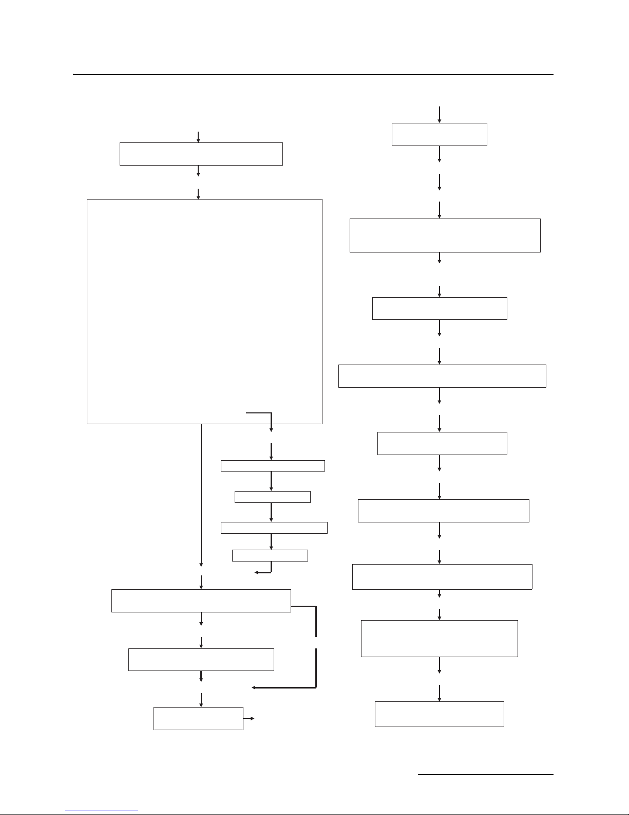
Each time a key is pressed an audible signal is emitted. Refer to
Figure 2-1 for a simplified flowchart showing the programming
procedure. At the back of this manual is a worksheet on which
program selections may be written.
2.3.1 Programming
Overview
First, the user should remember that the flow transmitter
always has a program stored in memory, even if it is only the
default program installed at the factory. In programming the
2-3

3020 Flow Transmitter
Section 2 Operation and Programming
3020, first select one of the yellow FUNCTION KEYS and press
it. The display will show the step number on the left and the
number of the choice currently selected (or the numerical value
entered for steps requiring a value) on the right. Not all steps
will be used in programming. For example, if there is no remote
plotter, Steps 11-15, which are involved with operation of the
plotter, will be skipped.
The program steps are printed on the flow transmitter label, and
normally programming proceeds in a logical manner, starting
with Step 1, which selects the units used for level measurement,
feet or meters. Step 2 is the selection of the primary measuring
device. Then maximum head, flow rate at maximum head, and
totalizer scaling are selected. If no other equipment is used with
the 3020, only Step 16, DISPLAY OPERATION, and Step 18,
LEVEL ADJUST, must be programmed. Then the LEVEL
ADJUST step is used to calibrate the ultrasonic level sensor.
Programming in Steps 10 through 15 and 17 occurs when the
flow transmitter is used with other equipment. Step 10 governs
the relationship between the flow transmitter and an associated
wastewater sampler. Steps 11 - 15 control the output to an Isco
High-Low Alarm Relay Box (a device to turn equipment on or off
when flow reaches or falls below preset levels), or a 2312. The
2312 is an electro-mechanical printer which records level or flow
information from the 3020 on a strip chart to provide a hard copy
of information measured by the flow transmitter. The 2312
printer is no longer sold by Teledyne Isco.
Step 17 determines the operation of the 4-20 mA current loop
output. Examples of equipment which would be connected to the
4-20 mA current loop are the Isco 2410 Circular Chart Recorder
or process equipment, such as a chlorinator.
If the flow transmitter is already installed and has been programmed, it is not necessary to completely re-program the unit
to enter any changes. Instead, simply select the yellow
FUNCTION KEY where the change needs to be made and press
ENTER/PROGRAM STEP until the desired step is reached; then
enter the change.
Automatic Program Advance – After the ENTER/PROGRAM
STEP key has been pressed, the display will automatically
advance to the next step and show the current choice or value
entered for that step; the process continues until the user has
made selections for all steps necessary to complete the yellow
FUNCTION KEY selected, or presses the CLEAR ENTRY key
twice to exit the program.
All programming for the 3020 can be done in the shop, except for
the ADJUST LEVEL step, which must be done at the job site.
2-4
FLOW RATE AT MAXIMUM
HEAD
(0.001 to 9,999)
Step 10 - Press Sampler Output
Steps 11 - 15 Press Plotter Output
Step 11 - Flow Rate Units on Plotter
Step 14 - Plotter Totalizer Zeros
Step 16 - Display Mode
Step 17 - 4-20 mA Output
Step 18 - Adjust Level
Step 9 -Totalizer
Step 8 - Flow Rate at Max. Head
Step 7 - Maximum Head
Selection 34 only (Equation)
Step 2 Select Primary Device
TOTALIZER
SCALING
(0 to 9,999)
6. P2 (0.1 to 3.0)
MAXIMUM HEAD:
(FEET 0.1 to 10.0) (METERS 0.03 to 3.04)
DISPLAY OPERATION
1. FLOW 2. LEVEL 3. ALTERNATE FLOW & LEVEL
CURRENT LEVEL
(FT. –1.0 to 10.0)(M –0.31 to
3.05)
4 - 20 mA OUTPUT OPERATION
1. FLOW 2. FLOW W/EVENT MARK
3. LEVEL 4. LEVEL W/EVENT MARK
RESET PLOTTER TOTALIZER TO
ZERO
SAMPLER SCALING
(0 to 9,999)
UNIT OF MEAS. FOR FLOW RATE ON PLOTTER
1. GPM 2. GPS 3. MGD 4. CFS 5. CMS 6. CMH
7. CMD 8. LPS 9. CFD 10. GPH 11. AFD. 12. CFH
ZEROS TO RIGHT OF FLOW
RATE DISPLAY (0 to 6)
UNIT OF MEAS. FOR TOTALIZED VOLUME ON
PLOTTER
1. CF 2. GAL 3. CM 4. AF 5. L. 6. MG
ZEROS TO RIGHT OF
TOTALIZER
(0 to 9)
Step 13 - Totalized Volume Units on Plotter
Step 12 - Plotter Flow Rate Zeros
(skipped if no zeros to right of display)
Step 15 - Reset Plotter Totalizer
3. N1 (–4,999 to 4,999)
4. P1 (0.1 to 3.0)
5. N2 (–4,999 to 4,999)
To Remainder of Program
(Equation Only)
Step 1 Units of Measure for Level
1. FEET 2. METERS
Steps 1-9 Press PRIMARY DEVICE
Step 1 Select Units of Measurement
1. V-NOTCH WEIR
2. RECTANG. WEIR W/END
CONTRACTIONS
3. RECTANG. WEIR W/O
END CONTRACTIONS
4. CIPOLLETTI
5. PARSHALL 1"
6. PARSHALL 2"
7. PARSHALL 3"
8. PARSHALL 6"
9. PARSHALL 9"
10. PARSHALL 12"
11. PARSHALL 18"
12. PARSHALL 24"
13. PARSHALL 36"
14. PALMER-BOWLUS 6"
15. PALMER-BOWLUS 8"
16. PALMER-BOWLUS 10"
17. PALMER-BOWLUS 12"
18. PALMER-BOWLUS 15"
19. PALMER-BOWLUS 18"
20. PALMER-BOWLUS 24"
21. PALMER-BOWLUS 30"
22. PALMER-BOWLUS 48"
23. TRAPEZOID LARGE 60o V
24. TRAPEZOID 2" 45o WSC
25. TRAPEZOID 12" 45o
SRCRC
26. “H” FLUME 0.5’
27. “H” FLUME 0.75’
28. “H” FLUME 1’
29. “H” FLUME 1.5’
30. “H” FLUME 2’
31. “H” FLUME 3’
32. “H” FLUME 4.5’
33. LEVEL ONLY
34. EQUATION (SEE STEPS
3-6)
3020 Flow Transmitter
Section 2 Operation and Programming
Figure 2-1 Simplified Flowchart Programming Flowchart for the 3020
2-5

3020 Flow Transmitter
Note
Note
Note
Section 2 Operation and Programming
2.3.2 List of Program Steps Following is a list of the program steps used in the 3020 along
with the choices available or applicable range of values. Following the list is a detailed explanation of the purpose for each
step and the choices offered.
1. Select Units of level measurement. 1. Feet 2. Meters
2. Primary Device. (See list of devices above or refer to front
panel label.)
Steps 2 - 5 are programmed only if #34, Equation, is chosen in
Step 1.
3. N1 (-4,999 to 4,999)
4. P1 (0.1 to 3.0)
5. N2 (-4,999 to 4,999)
6. P2 (0.1 to 3.0)
7. Maximum Head in Feet (0.1 to 12.0)
8. Flow Rate at Maximum Head (0.001 to 9999)
9. Totalizer Scaling (Number of counts totalized per hour of
flow at maximum head; 0-9,999.)
Step 10 is programmed only if the flow transmitter is connected
to a sampler.
10. Sampler Scaling (Number of sampler pulses per hour at
maximum head; 0-9,999.)
Steps 11 to 15 are programmed only if an Isco 2312 Plotter is
installed.
11. Unit of Measure for Flow Rate on Remote Plotter
1. GPM 2. GPS 3. MGD4. CFS 5. CMS 6. CMH
7. CMD 8. LPS 9. CFD 10. GPH 11. AFD 12. CFH
12. Zeros to Right of Flow Rate Display (0 to 6) if value of Step
7 is 1000
13. Unit of Measure for Totalized Volume on Remote Plotter
1. CF 2. GAL 3. CM 4. AF 5. L 6. MG
14. Zeros to Right of Totalizer (0 to 9)
15. Reset Plotter Totalizer to Zero (1.Yes 2. No)
16. Display Operation (1. Flow rate 2. Level 3. Alternate
between the flow and level.)
2-6

3020 Flow Transmitter
Note
QflowrateKN1H
P1
N2 HP2+=
Section 2 Operation and Programming
Step 17 is programmed only if the 3020 is connected to external equipment which operates with the standard 4-20 mA current loop.
17. 4-20 mA Output Operation (level, flow rate, with or without event mark.)
1. Transmit Flow Rate 2. Transmit Flow Rate with Event
Mark 3. Transmit Level 4. Transmit Level with Event
Mark
18. Adjust Level - Current Level in: (Feet -1.0 to 12.5) (Meters
-0.31 to 3.81.)
2.3.3 Description of
Program Steps
Following is an explanation for the program steps from the list
above.
Step 1 – In the first step of the program, select the units used for
level measurement, feet or meters.
Step 2 – In the second step of the programming sequence,
identify the primary measuring device used; then choose the
number referring to that device from the list printed on the label
or in the table on the next page. Thirty-two common primary
measuring devices are supported by the 3020. If the flow transmitter is used to measure level only, select #33. If an equation is
to be used, select #34, and continue as follows.
Steps 3 - 6 – These steps will only appear on the display and be
used when #34, Equation, is selected and allow the user to
program the values N1, P1, N2, and P2 for the general flow
equation:
(See Section 2.4.3 for a detailed discussion about the equation.)
With any choice but #34 in Step 2, the program advances automatically to Step 7.
Step 7 - MAXIMUM HEAD – The flow transmitter will request
entry of a value for MAXIMUM HEAD. The flow transmitter will
display the value already in memory. Possible values entered
here will range from 0.1 to 12 feet (0.03 - 3.7 m). Always select a
value for maximum head which is reasonable for your particular
application, rather than the maximum value allowable, as the
accuracy of the level-to-flow rate conversion will be based on this
value.
Step 8 – Step 8 requests entry of flow rate at maximum head.
Values range from of 0.001 to 9,999. Remember to base the flow
rate at maximum head on the value you entered in Step 7, rather
than the maximum head allowable for the device. This information is available from the manufacturer of the primary measuring device used. The information is also available from tables
published for specific devices in the Isco Open Channel Flow
Measurement Handbook.
2-7

3020 Flow Transmitter
Section 2 Operation and Programming
If the value you must enter is greater than 9,999, you must
round it off and reduce it to a number which can be displayed by
the flow transmitter. For example 32,537 GPM is greater than
the four digits available on the display. So, first we round the
number to 32,540 and then enter the four most significant digits
into the flow transmitter: 3 - 2 - 5 - 4. To show the overflow from
the display we attach a 0 label to the right of the display to
indicate the value displayed is in tens of gallons rather than
gallons. Finally, attach a label for the appropriate units, in this
case, GPM.
If the installation includes a 2312 Plotter, these same flow rate
units will be entered in Step 11 and the number of zeroes will be
entered in Step 12. For the example of 32,537 GPM, you would
enter 1 (GPM) in Step 11 and 1 in Step 12.
Step 9 – The flow transmitter will ask for scaling for the flow
totalizer. This is the number of counts on the totalizer per hour of
flow at maximum head. The value entered ranges from 0 to
9,999. The selection of the number of counts per hour is based on
flow at maximum head, so the actual number of counts may be
much lower.
If the installation includes a 2312 Plotter, the units of measure
selected for this step will also be entered for the 2312 in Step 13
and the number of zeroes in Step 14. For example, if you want to
totalize in cubic feet and the flow rate at maximum head is 72.5
CFS:
72.5 CFS x 60 sec./min. x 60 min./hr. = 261,000 cubic feet
per hour (CFH)
For this example, each count on the totalizer equals 1,000 cubic
feet.
261,000 CFH 1,000 CF/count = 261 counts per hour
You would then enter 2 - 6 - 1 for this step. In this instance you
would place three 0 labels and the CF label to the right of the
display. If the 3020 is connected to a 2312, you would then enter
1 (CF) in Step 13 and 3 in Step 14.
Step 10 – The flow transmitter requests selection of sampler
scaling (flow pulses to the sampler). This step need not be programmed unless the 3020 is being used with an associated
wastewater sampler. The purpose of this program step is to
provide signals to the associated sampler to take flow-paced
samples. The range is from 0 to 9,999 pulses per hour. The
number is determined in the same way as in Step 9, above.
Selection of the number of flow pulses to the sampler per hour is
based on flow rate at maximum head, so the actual number of
pulses per hour may be considerably lower. The number chosen
2-8

3020 Flow Transmitter
Section 2 Operation and Programming
should be determined by the volume of flow that must pass
through the primary device before a sample is taken, rather than
a particular interval of time.
For example, assume the flow rate at maximum head for a particular installation is 32,540 GPM.
32,540 GPM x 60 min./hr. = 1,952,400 gallons/hour (GPH)
We want to send a flow pulse to the associated wastewater
sampler every 10,000 gallons.
1,952,400 GPH 10,000 gallons/pulse = 195 pulses/hour
You would then enter 1 - 9 - 5. If the associated wastewater
sampler is programmed to take a sample every 50 pulses, it will
be taking a sample every 500,000 gallons.
10,000 gallons /pulse x 50 pulses per sample = 500,000
gallons/sample
If the sampler is programmed to take a sample every 200 pulses,
it will be taking a sample every 2,000,000 gallons.
10,000 gallons/pulse x 200 pulses per sample = 2,000,000
gallons/sample
Steps 11 to 15 – Plotter Output - These steps need to be pro-
grammed only if the 3020 is used with an Isco 2312 Plotter.
Selections made in Steps 11 - 15 will determine the operation of
the 2312. The selections made here do not affect the way the
3020 operates. However, values chosen should be consistent with
choices made for earlier steps.
Step 11 – Units of Measure for Flow Rate on Remote Plotter Several selections for units-of-measure are provided here, which
will be the units printed out on the chart of the 2312. Units
selected should be the same as selected for Step 8.
Step 12 – Zeros to the Right of the Flow Rate Display (0 to 6) This step is programmed with the number of zeroes overflowing
the display from the value entered in Step 8. The remote plotter
displays flow rate with scientific notation. For example, a plotter
display of 5.57E+3 would equal 5.57 x 10
3
, which is the same as
5.57 x 1,000 and that is 5,570.
Step 13 – Units of Measure for Totalized Volume on Remote
Plotter - Again, selection is dependent on the units of measure
selected for a previous step, in this case, Step 9.
Step 14 – Zeros to Right of Totalizer (0 to 9) - This step allows for
the addition of the correct number of trailing zeros to be added to
the plotter's totalizer to make meaningful numbers where large
2-9

3020 Flow Transmitter
CAUTION
Section 2 Operation and Programming
flow rates are involved. The number selected is the same as the
number of zeroes overflowing the display in Step 9. Again, these
are actually expressed on the plotter's display in terms of scientific notation, so there is no need to add stickers to the plotter's
display.
Step 15 – Reset Plotter Totalizer to Zero - This step allows the
user the option to reset the totalizer on the remote plotter. It does
not affect the mechanical totalizer on the 3020. An example of
where this might be used is studies of flow over specific periods of
time. It might be convenient to reset the flow totalizer between
each study. This is a user/application- determined option. The
totalizer is reset whenever power is turned off.
Step 16 – Display Operation - This step offers the option of
choosing the method of display which is most useful for a particular application. Choose between: 1. Flow Rate or 2. Level
being displayed, or select 3. Alternate, which will cause the
display to switch between level and flow rate. This step defines
the display when the flow transmitter is in normal operation.
The appearance of the letter H on the left side of the display designates level (or Head).
Step 17 – 4-20 mA Output Operation - This step determines how
associated external equipment connected to the 3020 through the
4-20 mA current loop will operate. The selection of 1. Flow Rate
and 3. Level are user/application specified. The selections of 2.
Flow Rate with Event Mark and 4. Level with Event Mark
are specifically intended for use only with the Isco 2410 Circular
Chart Recorder to indicate on the chart that an associated wastewater sampler has taken a sample.
Do not transmit level or flow rate with event marks to any
equipment other than a circular or strip chart recorder.
Transmission of event marks causes momentary jumps of the
4-20 mA loop current to 100% (full-scale) operation. This could
cause erratic operation of some process control equipment
and could possibly have hazardous consequences with certain
equipment.
This output, which is a variable DC current of 4-20 mA, changes
with the level or flow rate measured by the 3020: 4 mA = 0% flow
or 0 level; 20 mA = 100% flow rate, full-scale, or maximum head.
The 4-20 mA current output is an industrial control standard
and is used to provide an analog (variable) signal reflecting
changing levels or flow rates to related equipment which
responds to the changing conditions measured by the flow transmitter. This operation can be compared to a lamp controlled by a
dimmer. The lamp can burn at various levels of brightness
between fully off and fully on. Contrast this with equipment controlled by being turned completely on or off.
Step 18 – Adjust Level - This step allows for the adjustment of
displayed level in the 3020. There are various ways to calibrate
the ultrasonic level sensor after it has been installed, depending
2-10

3020 Flow Transmitter
Note
Section 2 Operation and Programming
on the device used. Then, measurement from the zero (level)
point of the primary device to the surface of the flow stream is
done, very carefully, to determine the level in the flow stream.
Commonly this is done by using a measuring staff.
You may enter this level into the 3020 by adjusting the displayed
level with the up and down arrow keys, or by entering the
desired value with the numeric keys. The flashing letter H
denotes head (level).
If the flow transmitter shows negative level or flow rate during
initial setup and displays codes with EE on the left side of the
display, the level should be adjusted (Step 18) to a positive
value and then answer all the questions associated with selecting a primary device. This should stabilize the display.
2.3.4 Equations Used in
Flow Conversion
2.3.5 Default Program You will program the flow transmitter with selections from the
The equations used in the flow conversions built into the 3020
Flow Transmitter are shown in Table 2-1. For those primary
devices for which the flow conversions consist of data only
(Palmer-Bowlus flumes, “H” flumes, and Trapezoidal flumes), the
equations used are approximations which fit the manufacturer's
listed data within 1% of full-scale flow rate. If you desire to use
level-to-flow rate conversions other than those built into the flow
transmitter, #34, equation should be selected in Step 1. Section
2.4.3 has a discussion of the use of the equation followed by two
programming examples, including a rectangular weir with end
contractions.
menus appropriate to your particular installation. When the flow
transmitter is shipped, there is already a default program in
memory, which was used to test the unit. Understand that this is
only an example program to allow testing of the unit as it is manufactured. It is not intended to fit any particular application.
2-11

3020 Flow Transmitter
Section 2 Operation and Programming
Table 2-1 Equations Used in the 3020
Type and # of Device Flow Equation
1.5
Q = KH
2.5
- 0.034H
1.5
1.5
1.55
1.55
1.55
1.58
1.53
1.52
1.53
1.53
1.54
1. V-Notch Weir Q = KH
2. Rectangular Weir
with End Contractions
Q = K(1.034H
(see Section 2.4.3)
3. Rectangular Weir
without End Contractions
4. Cipolletti Weir Q = KH
5-13. Parshall Flume
5. 1”
6. 2”
7. 3”
8. 6”
9. 9”
10. 12”
11. 18”
12. 24”
13. 36”
Q = KH
Q = KH
Q = KH
Q = KH
Q = KH
Q = KH
Q = KH
Q = KH
Q = KH
2.5
)
14-22. Palmer-Bowlus Flume
14. 6”
15. 8”
16. 10”
17. 12”
18. 15”
19. 18”
20. 24”
21. 30”
22. 48”
Q = KH
Q = KH
Q = KH
Q = KH
Q = KH
Q = KH
Q = KH
Q = KH
Q = KH
1.9
1.9
1.9
1.9
1.9
1.9
1.9
1.9
**
1.9
23-25. Trapezoidal Flume*
23. Large 60° V
24. 2” 45° WSC
25. 12” 45° SRCRC
Q = KH
Q = KH
Q = KH
2.32
2.29
**
2.58
26-32. “H” Flume
26. 0.5’
27. .75’
28. 1.0”
29. 1.5’
30. 2.0’
31. 3.0’
32. 4.5’
Q = KH
Q = KH
Q = KH
Q = KH
Q = KH
Q = KH
Q = KH
2.31
2.31
2.31
2.31
2.31
2.31
**
2.31
* Palmer-Bowlus and Trapezoidal Flumes manufactured by Plasti-Fab,
Tualatin, Oregon.
**Flow equations for Palmer-Bowlus, “H,” and Trapezoidal Flumes are
approximations that fit data within 1% of full-scale flow rate.
2-12

3020 Flow Transmitter
1
1
2
8
7
1.5
Section 2 Operation and Programming
2.4 Programming
Examples
2.4.1 Programming for a
Parshall Flume
In the following sections programming examples are described to
show with keystroke entries how the 3020 Flow Transmitter is
set up for proper operation in specific applications. When programming the flow transmitter, note that the number on the left
side of the display is the PROGRAM STEP while the number on
the right is the current value.
In this example, we will go through the programming steps necessary to select a 6" Parshall flume with a maximum head of
1.5 feet. Flow rate will be displayed in GPM. The flow rate at
maximum head in GPM is 1754 GPM. This value is available
either from the manufacturer of the flume, or can be found in the
Isco Open Channel Flow Measurement Handbook. The totalizer
will be set to totalize in gallons, and the 4-20 mA output will be
set up to transmit level with 100 percent equal to 1.5 feet.
Assume that the level, which would be measured with a staff
gauge or other measuring device, is 0.75 feet. Attach the GPM
sticker to the right of the display.
Calculations for example 1 – The totalizer will read out in
gallons. To find the flow per hour at maximum head multiply
the flow in GPM by 60 (1754 gallons per minute x 60 minutes per
hour = 105,240 gallons per hour). The totalizer scaling value can
only be a value from 0 to 9,999. Since 105,240 is larger than
9,999, we divide by 100 (105,240 100 = 1,052).
1. Press PRIMARY DEVICE.
2. Select units of measure for level. To select feet, press 1.
Press ENTER.
3. Select the primary device from the list shown on the front
panel. To select a 6-inch Parshall Flume, press 8.
Press ENTER.
4. Enter the maximum expected head in feet. For this example, press 1, (decimal), 5.
Press ENTER.
2-13

3020 Flow Transmitter
8
1754
9 1052
H XXXX
H is for Height
(level).
16 1
XXXX
(Flow Rate)
17 3
XXXX
(Flow Rate)
Section 2 Operation and Programming
Press ENTER. Place the “GPM” label to the right of the display.
Press ENTER.
The totalized flow in gallons would be the totalizer value x 100,
so attach two “0” labels and the “GAL” label to the right of the
display.
5. Enter the flow at maximum head, 1754 GPM. Press 1, 7, 5
4.
6. To enter the totalizer scaling, calculated above, press 1, 0,
5, 2.
7. Press the DISPLAY OPERATION key to set the display.
Press 1.
Press ENTER.
8. Press the 4-20 MA OUTPUT key to select the information
to transmit. For this example, we want to transmit level.
To select “transmit level,” press 3.
Press ENTER.
2-14
 Loading...