

Teledyne 3010TAC User Manual

Oxygen Analyzer
OPERATING INSTRUCTIONS FOR
Model 3010TAC
Trace Oxygen Analyzer
Flush Mount Control Unit, PN D-66192A
CENELEC Type Remote Probe, PN C-66336
Intrinsic Safe Barriers Assy., PN C-67564
DANGER
HIGHLY TOXIC AND OR FLAMMABLE LIQUIDS OR GASES MAY BE PRESENT IN THIS
MONITORING SYSTEM.
PERSONAL PROTECTIVE EQUIPMENT MAY BE REQUIRED WHEN SERVICING THIS SYSTEM.
HAZARDOUS VOLTAGES EXIST ON CERTAIN COMPONENTS INTERNALLY WHICH MAY PER-
SIST FOR A TIME EVEN AFTER THE POWER IS TURNED OFF AND DISCONNECTED.
ONLY AUTHORIZED PERSONNEL SHOULD CONDUCT MAINTENANCE AND/OR SERVICING.
BEFORE CONDUCTING ANY MAINTENANCE OR SERVICING CONSULT WITH AUTHORIZED
SUPERVISOR/MANAGER.
Teledyne Analytical Instruments
P/N M66394
11/22/99
ECO#:99-0459
i

Model 3010TAC
Copyright © 1999 Teledyne Analytical Instruments
All Rights Reserved. No part of this manual may be reproduced, transmitted,
transcribed, stored in a retrieval system, or translated into any other language or computer
language in whole or in part, in any form or by any means, whether it be electronic,
mechanical, magnetic, optical, manual, or otherwise, without the prior written consent of
Teledyne Analytical Instruments, 16830 Chestnut Street, City of Industry, CA 91749-
1580.
Warranty
This equipment is sold subject to the mutual agreement that it is warranted by us
free from defects of material and of construction, and that our liability shall be limited to
replacing or repairing at our factory (without charge, except for transportation), or at
customer plant at our option, any material or construction in which defects become
apparent within one year from the date of shipment, except in cases where quotations or
acknowledgments provide for a shorter period. Components manufactured by others bear
the warranty of their manufacturer. This warranty does not cover defects caused by wear,
accident, misuse, neglect or repairs other than those performed by Teledyne or an authorized service center. We assume no liability for direct or indirect damages of any kind and
the purchaser by the acceptance of the equipment will assume all liability for any damage
which may result from its use or misuse.
We reserve the right to employ any suitable material in the manufacture of our
apparatus, and to make any alterations in the dimensions, shape or weight of any parts, in
so far as such alterations do not adversely affect our warranty.
Important Notice
This instrument provides measurement readings to its user, and serves as a tool by
which valuable data can be gathered. The information provided by the instrument may
assist the user in eliminating potential hazards caused by his process; however, it is
essential that all personnel involved in the use of the instrument or its interface, with the
process being measured, be properly trained in the process itself, as well as all instrumentation related to it.
The safety of personnel is ultimately the responsibility of those who control process
conditions. While this instrument may be able to provide early warning of imminent
danger, it has no control over process conditions, and it can be misused. In particular, any
alarm or control systems installed must be tested and understood, both as to how they
operate and as to how they can be defeated. Any safeguards required such as locks, labels,
or redundancy, must be provided by the user or specifically requested of Teledyne at the
time the order is placed.
Therefore, the purchaser must be aware of the hazardous process conditions. The
purchaser is responsible for the training of personnel, for providing hazard warning
methods and instrumentation per the appropriate standards, and for ensuring that hazard
warning devices and instrumentation are maintained and operated properly.
Analytical Instruments, the manufacturer of this instrument, cannot accept
responsibility for conditions beyond its knowledge and control. No statement expressed
or implied by this document or any information disseminated by the manufacturer or its
agents, is to be construed as a warranty of adequate safety control under the user’s process
conditions.
ii
Teledyne Analytical Instruments

Oxygen Analyzer
Table of Contents
Specific Model Information..................................iv
Preface ................................................................v
Part I: Control Unit, Model TAC............. Part I: 1-1
Part II: Intrinsic Safe Barriers and
Remote Probe ..........................Part II: 1-1
Appendix.........................................................A-1
Teledyne Analytical Instruments
iii

Model 3010TAC
Specific Model Information
The instrument for which this manual was supplied may incorporate one
or more options not supplied in the standard instrument. Commonly available
options are listed below, with check boxes. Any that are incorporated in the
instrument for which this manual was supplied are indicated by a check mark
in the box.
Model 3010TAC complies with all of the requirements of the Commonwealth of Europe (CE) for Radio Frequency Interference and Electromagnetic
Interference (RFI/EMI) protection.
❏ 19" Rack Mount
The 19" Relay Rack Mount units are available with either
one or two series 3010TAC analyzer Control Units installed in a standard 19" panel and ready to mount in a
standard rack. See Appendix for details.
❏ Cell Class* ____________________ (L-2C standard).
Enter Class Designation
* See Part II, Chapter 2 and/or any addendum that may be
attached to this manual for cell specifications.
iv
Teledyne Analytical Instruments

Oxygen Analyzer
Preface
Overview
The Teledyne Analytical Instruments Model 3010TAC Trace Oxygen
Analyzer is a versatile microprocessor-based instrument for detecting partsper-million (ppm) levels of oxygen in a variety of background gases. It is a
“split architecture” instrument. This means that a general purpose Control
Unit, designed for nonhazardous areas only, remotely controls a specially
designed Analysis Unit, or remote probe, that can operate in a hazardous
area. 3010TAC Analyzers meet or exceed all of the requirements of the
Commonwealth of Europe (CE) for Radio Frequency Interference and
Electromagnetic Interference (RFI/EMI) protection, and Low Voltage
Directive (LVD).
Part I of this manual covers the Model 3010TAC General Purpose flushpanel and/or rack-mount Control Unit only. This Control Unit is for indoor
use in a nonhazardous environment. The Intrinsic Safe Barriers assy is designed for indoor/outdoor nonhazardous environments only. The Analysis
Units (or Remote Probes), is for hazardous environments. Part II of this
manual covers the 3010TAC Remote Probe.
Typical Applications
A few typical applications of the Model 3010TAC are:
• Monitoring inert gas blanketing
• Air separation and liquefaction
• Chemical reaction monitoring
• Semiconductor manufacturing
• Petrochemical process control
• Quality assurance
• Gas analysis certification.
Teledyne Analytical Instruments
v

Model 3010TAC
Model and Part Number Designations
The part numbers are the most specific identification. When using this
manual for operation, maintenance, or ordering parts, check the part numbers
on your Instruments to be sure of a match. Where an underscore (_) appears
in a model number, the unit has more than one application. For example,
3010T_C means that the same unit is part of the 3010TAC and the 3010TBC
models.
3010TA-EU: NEC Type Trace O2 Analyzer with flush mount Control Unit
designed to meet CE requirements for RFI/EMI protection.
Control Unit D66192A remote probe C66778A (C66778B
6mm fittings).
3010TA: NEC Type Trace Oxygen Analyzer with flush mount
Control Unit. Consists of 3010TA Control Unit, PN
D-64596A and a 3010T Analysis Unit, PN D-65478.
3010PA: NEC Type Percent Oxygen Analyzer with flush mount
Control Unit. Consists of 3010PA Control Unit, PN
D-64596B or C and a 3010P Analysis Unit, PN D-65479.
3010TB: NEC type Trace Oxygen Analyzer with bulkhead mount
Control Unit. Consists of 3010TB/PB Control Unit, PN
D-66190A, and a 3010T Analysis Unit, PN D-65478.
3010PB: NEC type Percent Oxygen Analyzer with bulkhead mount
Control Unit. Consists of 3010TB Control Unit, PN D-66190
B or C, and a 3010T Analysis Unit, PN D-65479.
3010TAC: CENELEC type Trace Oxygen Analyzer with flush mount
Control Unit. Consists of 3010TA Control Unit, PN
D-66192A, and a 3010T_C Analysis Unit, PN C-66336.
3010PAC: CENELEC type Percent Oxygen Analyzer with flush mount
Control Unit. Consists of 3010PA Control Unit, PN D-66192
B or C, and a 3010P_C Analysis Unit, PN B-39923C.
3010TBC: CENELEC type Trace Oxygen Analyzer with bulkhead mount
Control Unit. Consists of 3010TB Control Unit, PN
D-66194A, and a 3010T_C Analysis Unit, PN C-66336.
3010PBC: CENELEC type Percent Oxygen Analyzer with bulkhead
mount Control Unit. Consists of 3010PB Control Unit, PN
D-66194 B or C, and a 3010P_C Analysis Unit, PN
B-39923C.
Options: See Specific Model Information sheet, on page iv for details.
vi
Teledyne Analytical Instruments

Oxygen Analyzer
Main Features of the Analyzer
The Model 3010TAC series Oxygen Analyzers are sophisticated yet
simple to use. The main features of these analyzers include:
• A 2-line alphanumeric display screen, driven by microprocessor
electronics, that continuously prompts and informs the operator.
• High resolution, accurate readings of oxygen content: from low
ppm levels through 25%. Large, bright, meter readout.
• Stainless steel cell block is standard equipment.
• Advance design Micro-Fuel Cell sensor, Specially designed
model for trace analysis, has a one year warranty and an
expected lifetime of two years.
• Versatile analysis over a wide range of applications.
• Microprocessor based electronics: 8-bit CMOS microprocessor
with 32 kB RAM and 128 kB ROM.
• Three user definable output ranges allow best match to users
process and equipment: 0-10 ppm through 0-250,000 ppm for
trace analysis.
• Air-calibration range for convenient spanning at 20.9 %.
• Auto Ranging allows analyzer to automatically select the proper
preset range for a given measurement. Manual override allows
the user to lock onto a specific range of interest.
• Two adjustable concentration alarms and a system failure alarm.
• Self-diagnostic testing, at startup and on demand, with continuous
power-supply monitoring.
• CE Compliance (EMC & LVD).
• RS-232 serial digital port for use with a computer or other digital
communications device.
• Analog outputs for Concentration and Analysis Range: 0–1 V dc
standard. Isolated 4–20 mA dc standard.
• Compact and versatile design: flush-panel, rack-mountable, or
bulkhead mounted Control Units available.
Teledyne Analytical Instruments
vii
Model 3010TAC
Model 3010TAC complies with all of the requirements of the
Commonwealth of Europe (CE) for Radio Frequency Interference,
Electromagnetic Interference (RFI/EMI), and Low Voltage Directive
(LVD).
The Analysis Unit is Intrinsically safe and CENELEC approved.
The Control Unit is suitable for general purpose areas. The probe is
CENELEC approved (certification code EEXIA IICT6).
The following International Symbols are used throughout the
Instruction Manual for your visual and immediate warnings and when
you ha ve to attend CAUTION while oper ating the instrument:
STAND-BY, Instrument is on Stand-by ,
but circuit is active
GROUND
Protective Earth
CAUTION, The operator needs to ref er to the
manual for further info rmation. Failure to do
so may compromise the saf e oper ation of the
equipment.
CA UTION, Risk of Electric Shock
viii
Teledyne Analytical Instruments

Part I: Control Unit
OPERATING INSTRUCTIONS
Model 3010TAC
Oxygen Analyzer
Pa rt I: Control Unit
Flush Panel Mount
Part Numbers: D-66192A
Teledyne Analytical Instruments
Part I: i

Model 3010TAC Oxygen Analyzer
Table of Contents
1 Introduction
1.1 Overview........................................................................ 1-1
1.2 Control Unit Front Panel................................................. 1-1
1.3 Recognizing Difference Between LCD & VFD............... 1-3
1.4 Control Unit Rear Panel................................................. 1-3
2 Operational Theory
2.1 Introduction .................................................................... 2-1
2.2 Electronics and Signal Processing ................................ 2-1
3 Installation
3.1 Unpacking the Control Unit............................................ 3-1
3.2 Mounting the Control Unit .............................................. 3-1
3.3 Electrical Connections................................................... 3-3
3.3.1 Primary Input Power .............................................. 3-4
3.3.2 50-Pin Interface Connector ................................... 3-4
3.3.3 RS-232 Port ......................................................... 3-9
3.3.4 Remote Probe Connection................................... 3-10
3.4 Testing the System......................................................... 3-11
4 Operation
4.1 Introduction .................................................................... 4-1
4.2 Using the Data Entry and Function Buttons ................... 4-2
4.3 The System Function ..................................................... 4-3
4.3.1 Tracking the O2 Readings during Calibration ......... 4-4
4.3.2 Setting up an Auto-Cal........................................... 4-5
4.3.3 Password Protection .............................................. 4-5
4.3.3.1 Entering the Password................................... 4-6
4.3.3.2 Installing or Changing the Password ............. 4-7
4.3.4 Logout.................................................................... 4-8
4.3.5 System Self-Diagnostic Test .................................. 4-9
ii: Par t I
Teledyne Analytical Instruments

Part I: Control Unit
4.3.6 Version Screen ...................................................... 4-10
4.3.7 Showing Negative Oxygen Readings.................... 4-10
4.4 The Zero and Span Functions ....................................... 4-10
4.4.1 Zero Cal................................................................. 4-10
4.4.1.1 Auto Mode Zeroing ........................................ 4-11
4.4.1.2 Manual Mode Zeroing.................................... 4-12
4.4.1.3 Cell Failure .................................................... 4-13
4.4.2 Span Cal................................................................ 4-13
4.4.2.1 Auto Mode Spanning ..................................... 4-13
4.4.2.2 Manual Mode Spanning................................. 4-14
4.4.3 Span Failure .......................................................... 4-16
4.5 The Alarms Function...................................................... 4-16
4.6 The Range Function ...................................................... 4-18
4.6.1 Setting the Analog Output Ranges......................... 4-19
4.6.2 Fixed Range Analysis ............................................ 4-19
4.7 The Analyze Function.................................................... 4-20
4.8 Signal Output ................................................................. 4-20
5 Maintenance
5.1 Fuse Replacement ......................................................... 5-1
5.2 System Self Diagnostic Test........................................... 5-2
5.3 Major Internal Components............................................ 5-3
5.4 Cleaning ........................................................................ 5-4
Teledyne Analytical Instruments
Part I: iii

Model 3010TAC Oxygen Analyzer
iv: Part I
Teledyne Analytical Instruments

Oxygen Analyzer Part I: Control Unit
Introduction
1.1 Overview
The Analytical Instruments, Remote Probe and Intrinsic Safe Barriers,
Model 3010TAC Analyzer Control Unit, together with a 3010TAC Analysis Unit, is a versatile microprocessor-based instrument for detecting trace
amounts of oxygen in a variety of gases.
Part I, this part, of this manual covers the Model 3010TAC General
Purpose flush-panel and/or rack-mount Control Unit. (The Remote Probe
is covered in Part III of this manual.) The Control Unit is for indoor use in
a nonhazardous environment only. Part III Remote Probe is designed for
hazardous environments.
1.2 Control Unit Front Panel
The standard 3010TAC Control Unit is housed in a rugged metal case
with all remote controls and displays accessible from the front panel. See
Figure 1-1. The front panel has a digital meter, an alphanumeric display,
and thirteen buttons for operating the analyzer.
Teledyne Analytical Instruments
Part I: 1-1

1 Introduction Model 3010TAC
Figure 1-1: Front of Unmounted Control Unit
Function Keys: Six touch-sensitive membrane switches are used to
change the specific function performed by the analyzer:
• Analyze Perform analysis for oxygen content of a sample gas.
• System Perform system-related tasks (described in detail in
chapter 4, Operation.).
• Span Span calibrate the analyzer.
• Zero Zero calibrate the analyzer.
• Alarms Set the alarm setpoints and attributes.
• Range Set up the 3 user definable ranges for the instrument.
Data Entry Keys: Six touch-sensitive membrane switches are used to
input data to the instrument via the alphanumeric VFD display:
• Left & Right Arrows Select between functions currently
displayed on the VFD screen.
• Up & Down Arrows Increment or decrement values of
functions currently displayed.
1-2: Part I
Teledyne Analytical Instruments

Oxygen Analyzer Part I: Control Unit
• Enter Moves VFD display on to the next screen in a series.
If none remains, returns to the Analyze screen.
• Escape Moves VFD display back to the previous screen in a
series. If none remains, returns to the Analyze screen.
Digital Meter Display: The meter display is a LED device that
produces large, bright, 7-segment numbers that are legible in any lighting.
It is accurate across all analysis ranges. The –TA models produce
continuous readout from 0-10,000 ppm and then switch to continuous
percent readout from 1-25 %.
Alphanumeric Interface Screen: The backlit VFD screen is an easyto-use interface between operator and analyzer. It displays values, options,
and messages that give the operator immediate feedback.
Standby Button: The Standby turns off the display and outputs,
but circuitry is still operating.
CAUTION: The power cable must be unplugged to fully
disconnect power from the instrument. When
chassis is exposed or when access door is open
and power cable is connected, use extra care to
avoid contact with live electrical circuits .
1.3 Recognizing Difference Between LCD & VFD
LCD has GREEN background with BLACK characters. VFD has
DARK background with GREEN characters. In the case of VFD - NO
CONTRAST ADJUSTMENT IS NEEDED.
1.4 Control Unit Rear Panel
The Control Unit rear panel, shown in Figure 1-2, contains the
electrical connectors for external inputs and outputs. The input/output
functions are described briefly here and in detail in the Installation chapter
of this manual.
Teledyne Analytical Instruments
Part I: 1-3

1 Introduction Model 3010TAC
Figure 1-2: Model 3010TAC Rear Panel
• Power Connection Universal AC power source.
• Analog Outputs 0-1 V dc concentration and 0-1 V dc
range ID. Isolated 4-20 mA dc and 4-20
mA dc range ID.
• Alarm Connections 2 concentration alarms and 1 system
alarm.
• RS-232 Port Serial digital concentration signal
remote control valve.
• Remote Valve Provides all electrical interconnect to
the Analysis Unit or Remote Probe.
• Remote Span/Zero Digital inputs allow external control of
analyzer calibration.
• Calibration Contact To notify external equipment that
instrument is being calibrated and
readings are not monitoring sample.
• Range ID Contacts Four separate, dedicated, range relay
contacts. Low, Medium, High, Cal.
1-4: Part I
Teledyne Analytical Instruments

Oxygen Analyzer Part I: Control Unit
• Remote Probe Receives remote probe signals
• Network I/O Serial digital communications for local
network access. For future expansion.
Not implemented at this printing.
Note: If you require highly accurate Auto-Cal timing, use external
Auto-Cal control where possible. The internal clock in the
Model 3010TAC is accurate to 2-3 %. Accordingly, internally
scheduled calibrations can vary 2-3 % per day.
Teledyne Analytical Instruments
Part I: 1-5

1 Introduction Model 3010TAC
1-6: Part I
Teledyne Analytical Instruments

Oxygen Analyzer Part I: Control Unit
Operational Theory
2.1 Introduction
The Model 3010TAC Oxygen Analyzer Control Unit uses an 8031
microcontroller with 32 kB of RAM and 128 kB of ROM to control all
signal processing, input/output, and display functions for the Model
3010TAC analyzer. (The sample system and Micro-Fuel Cell sensor are
covered in Part III, Remote Probe, in this manual.) System power is supplied from a universal power supply module designed to be compatible
with any international power source.
2.2 Electronics and Signal Processing
All of the Analyzer electronics are located on Printed Circuit Board
(PCB) assemblies inside the Control Unit chassis. The PCB locations are
illustrated in section 5, Maintenance.
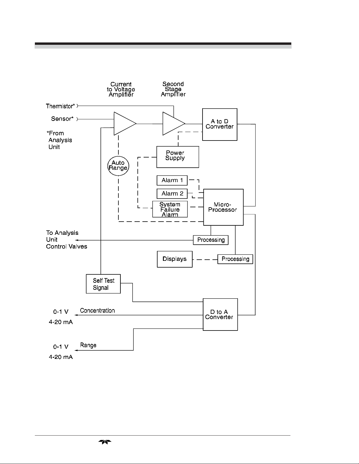
Refer to Figure 2-1, Block Diagram of the 3010TAC Electronics:
In the presence of oxygen, the sensor (in the Analysis Unit) generates
a current. A current to voltage amplifier (in the Control Unit) converts this
current to a voltage.
The second stage amplifier amplifies the voltage. It also uses a signal
from the thermistor (which is physically located in the Analysis Unit cell
block) to provide temperature compensation for the sensor signal. The
thermistor is a temperature dependent resistance that changes the gain of
the amplifier in proportion to the temperature changes in the block. This
thermistor signal compensates for the change in the cell output due to the
temperature changes. The result is a signal that is temperature independent.
The output from the second stage amplifier is sent to an 18-bit analog to
digital converter controlled by the microprocessor.
Teledyne Analytical Instruments
Part I: 2-1
2 Operational Theory Model 3010TAC
2-2: Part I
Figure 2-1: Block Diagram of the 3010TAC
Teledyne Analytical Instruments

Oxygen Analyzer Part I: Control Unit
The digital concentration signal—along with input from the control
panel—is processed by the microprocessor, and appropriate control signals
are directed to the display, alarms and communications port as well as to
the gas control valves in the Analysis Unit.
The same digital information is also sent to a 12 bit digital to analog
converter that produces the 4-20 mA dc and the 0-1 V dc analog concentration signal outputs, and the analog range ID outputs.
The microprocessor monitors the power supply, and activates the
system failure alarm if a malfunction is detected.
Teledyne Analytical Instruments
Part I: 2-3

2 Operational Theory Model 3010TAC
2-4: Part I
Teledyne Analytical Instruments

Oxygen Analyzer Part I: Control Unit
Installation
Installation of Model 3010TAC Analyzers includes:
1. Unpacking, mounting, and interconnecting the Control Unit and
the Analysis Unit
2. Making gas connections to the system
3. Making electrical connections to the system
4. Testing the system.
This chapter covers installation of the Control Unit. (Installation of
the Analysis Unit is covered in Part II of this manual.)
3.1 Unpacking the Control Unit
The analyzer is shipped with all the materials you need to install and
prepare the system for operation. Carefully unpack the Control Unit and
inspect it for damage. Immediately report any damage to the shipping
agent.
3.2 Mounting the Control Unit
The Model 3010TAC Control Unit is for indoor use in a general
purpose area. It is NOT for hazardous environments of any type.
The standard model is designed for flush panel mounting. Figure 3-1
is an illustration of a Model 3010 standard Control Unit front panel and
mounting bezel. There are four mounting holes—one in each corner of the
rigid frame. Drawing number D-66192, at the back of this manual, contains a panel cutout diagram.
On special order, a 19" rack-mounting can be provided. Per order, one
or two 3010TAC series Control Units are flush-panel mounted on the 19"
rack panel. See Figure 3-2.
Teledyne Analytical Instruments
Part I: 3-1

3 Installation Model 3010TAC
Figure 3-1: Front Panel of the Model 3010TAC Control Unit
Figure 3-2: Single and Dual 19" Rack Mounts
All operator controls are mounted on the control panel, which is
hinged on the left edge and doubles as a door to provide access to the
internal components of the instrument. The door is spring loaded and will
swing open when the button in the center of the latch (upper right corner)
3-2: Part I
Teledyne Analytical Instruments
Oxygen Analyzer Part I: Control Unit
is pressed all the way in with a narrow gauge tool (less than 0.18 inch
wide), such as a small hex wrench or screwdriver Allow clearance for the
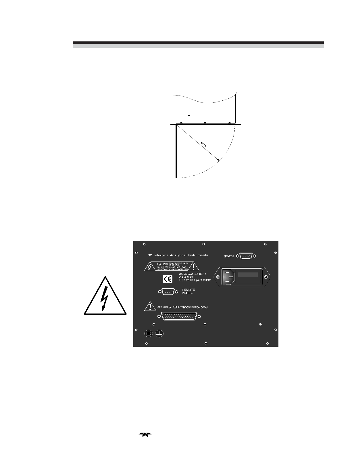
door to open in a 90-degree arc of radius 7.125 inches. See Figure 3-3.
Figure 3-3: Required Front Door Clearance
3.3 Electrical Connections
Figure 3-4 shows the Control Unit rear panel. Connections for power,
communications, and other system interfaces
Figure 3-4: Rear Panel of the Model 3010TAC Control Unit
For safe connections, no uninsulated wiring should be able to come in
contact with fingers, tools or clothing during normal operation.
Teledyne Analytical Instruments
Part I: 3-3
3 Installation Model 3010TAC
CAUTION: Use Shielded Cables. Also, use plugs that provide
excellent EMI/RFI protection. The plug case must
be connected to the cable shield, and it must be
tightly fastened to the analyzer with its fastening
screws. Ultimately, it is the installer who ensures
that the connections provide adequate EMI/RFI
sielding.
3.3.1 Primary Input Power
CAUTION: Power is applied to the instrument's circuitry as
long as the instrument is connected to the power
source. The switch on the front panel is for
switching power on or off to the displays and
outputs only.
The power cord receptacle and fuse block are located in the same
assembly. Insert the power cord into the power cord receptacle.
The universal power supply requires a 85–250 V ac, 47-63 Hz power
source.
Fuse Installation: The fuse block, at the right of the power cord
receptacle, accepts US or European size fuses. A jumper replaces the fuse
in whichever fuse receptacle is not used. Fuses are not installed at the
factory. Be sure to install the proper fuse as part of installation. (See Fuse
Replacement in chapter 5, maintenance.)
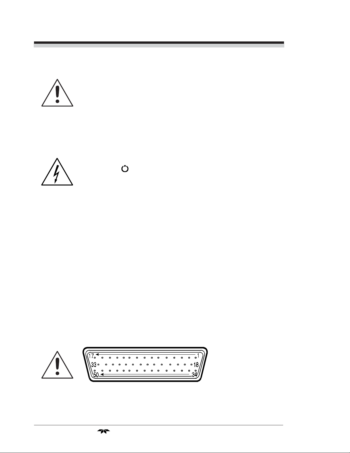
3.3.2 50-Pin Equipment Interface Connector
Figure 3-4 shows the pin layout of the Equipment Interface connector.
The arrangement is shown as seen when the viewer faces the rear panel of
the analyzer. The pin numbers for each input/output function are given
where each function is described in the paragraphs below.
Figure 3-4: Equipment Interface Connector Pin Arrangement
3-4: Part I
Teledyne Analytical Instruments

Oxygen Analyzer Part I: Control Unit
Analog Outputs: There are four DC output signal pins—two pins
per output. For polarity, see Table 3-1. The outputs are:
0–1 V dc % of Range: Voltage rises linearly with increasing oxygen,
from 0 V at 0 ppm to 1 V at full scale ppm. (Full
scale = 100% of programmable range.)
0–1 V dc Range ID: 0.25 V = Low Range, 0.5 V = Medium Range,
0.75 V = High Range, 1 V = Air Cal Range.
4–20 mA dc % Range: Current increases linearly with increasing oxygen,
from 4 mA at 0 ppm to 20 mA at full scale ppm.
(Full scale = 100% of programmable range.)
4–20 mA dc Range ID: 8 mA = Low Range, 12 mA = Medium Range, 16
mA = High Range, 20 mA = Air Cal Range.
Table 3-1: Analog Output Connections
Pin Function
3 + Range ID, 4-20 mA, floating
4 – Range ID, 4-20 mA, floating
5 + % Range, 4-20 mA, floating
6 – % Range, 4-20 mA, floating
8 + Range ID, 0-1 V dc
23 – Range ID, 0-1 V dc, negative ground
24 + % Range, 0-1 V dc
7 – % Range, 0-1 V dc, negative ground
Alarm Relays: The nine alarm-circuit connector pins connect to the
internal alarm relay contacts. Each set of three pins provides one set of
Form C relay contacts. Each relay has both normally open and normally
closed contact connections. The contact connections are shown in Table
3-2. They are capable of switching up to 3 amperes at 250 V ac into a
resistive load. The connectors are:
Threshold Alarm 1: • Can be configured as high (actuates when concen-
tration is above threshold), or low (actuates when
concentration is below threshold).
• Can be configured as failsafe or nonfailsafe.
• Can be configured as latching or nonlatching.
• Can be configured out (defeated).
Threshold Alarm 2: • Can be configured as high (actuates when concen-
tration is above threshold), or low (actuates when
concentration is below threshold).
Teledyne Analytical Instruments
Part I: 3-5
 Loading...