

Page 1

Oxygen Analyzer
OPERATING INSTRUCTIONS
Model 3010PAC
Percent Oxygen Analyzer
Flush Mount Control Unit, PN D-66192B
CENELEC Type Remote Probe, PN B-39923C
Intrinsic Safe Barriers Assy., PN C-66426
DANGER
HIGHLY TOXIC AND OR FLAMMABLE LIQUIDS OR GASES MAY BE PRESENT IN THIS
MONITORING SYSTEM.
PERSONAL PROTECTIVE EQUIPMENT MAY BE REQUIRED WHEN SERVICING THIS SYSTEM.
HAZARDOUS VOLTAGES EXIST ON CERTAIN COMPONENTS INTERNALLY WHICH MAY PER-
SIST FOR A TIME EVEN AFTER THE POWER IS TURNED OFF AND DISCONNECTED.
ONLY AUTHORIZED PERSONNEL SHOULD CONDUCT MAINTENANCE AND/OR SERVICING.
BEFORE CONDUCTING ANY MAINTENANCE OR SERVICING CONSULT WITH AUTHORIZED
SUPERVISOR/MANAGER.
Teledyne Analytical Instruments
P/N M66395
08/06/99
ECO # 99-0323
i
Page 2

Model 3010PAC
Copyright © 1999 Teledyne Analytical Instruments
All Rights Reserved. No part of this manual may be reproduced, transmitted,
transcribed, stored in a retrieval system, or translated into any other language or computer
language in whole or in part, in any form or by any means, whether it be electronic,
mechanical, magnetic, optical, manual, or otherwise, without the prior written consent of
Teledyne Analytical Instruments, 16830 Chestnut Street, City of Industry, CA 91749-
1580.
Warranty
This equipment is sold subject to the mutual agreement that it is warranted by us
free from defects of material and of construction, and that our liability shall be limited to
replacing or repairing at our factory (without charge, except for transportation), or at
customer plant at our option, any material or construction in which defects become
apparent within one year from the date of shipment, except in cases where quotations or
acknowledgements provide for a shorter period. Components manufactured by others bear
the warranty of their manufacturer. This warranty does not cover defects caused by wear,
accident, misuse, neglect or repairs other than those performed by Teledyne or an authorized service center. We assume no liability for direct or indirect damages of any kind and
the purchaser by the acceptance of the equipment will assume all liability for any damage
which may result from its use or misuse.
We reserve the right to employ any suitable material in the manufacture of our
apparatus, and to make any alterations in the dimensions, shape or weight of any parts, in
so far as such alterations do not adversely affect our warranty.
Important Notice
This instrument provides measurement readings to its user, and serves as a tool by
which valuable data can be gathered. The information provided by the instrument may
assist the user in eliminating potential hazards caused by his process; however, it is
essential that all personnel involved in the use of the instrument or its interface, with the
process being measured, be properly trained in the process itself, as well as all instrumentation related to it.
The safety of personnel is ultimately the responsibility of those who control process
conditions. While this instrument may be able to provide early warning of imminent
danger, it has no control over process conditions, and it can be misused. In particular, any
alarm or control systems installed must be tested and understood, both as to how they
operate and as to how they can be defeated. Any safeguards required such as locks, labels,
or redundancy, must be provided by the user or specifically requested of Teledyne at the
time the order is placed.
Therefore, the purchaser must be aware of the hazardous process conditions. The
purchaser is responsible for the training of personnel, for providing hazard warning
methods and instrumentation per the appropriate standards, and for ensuring that hazard
warning devices and instrumentation are maintained and operated properly.
Analytical Instruments, the manufacturer of this instrument, cannot accept
responsibility for conditions beyond its knowledge and control. No statement expressed
or implied by this document or any information disseminated by the manufacturer or its
agents, is to be construed as a warranty of adequate safety control under the user’s process
conditions.
ii
Teledyne Analytical Instruments
Page 3

Oxygen Analyzer
Table of Contents
Specific Model Information..................................iv
Preface ................................................................v
Part I: Control Unit, Model PAC.............Part I: 1-1
Part II: Intrinsic Safe Barriers ...............Part II: 1-1
Remote Probe ...........................................
Appendix......................................................... A-1
Teledyne Analytical Instruments
iii
Page 4

Model 3010PAC
Specific Model Information
The instrument for which this manual was supplied may incorporate
one or more options not supplied in the standard instrument. Commonly
available options are listed below, with check boxes. Any that are incorporated in the instrument for which this manual was supplied are indicated by a
check mark in the box.
Instrument Serial Number: __________________________
❏ 19" Rack Mount
The 19" Relay Rack Mount units are available with either
one or two series 3010PAC analyzer Control Units installed in a standard 19" panel and ready to mount in a
standard rack. See Appendix for details.
❏ Cell Class* ____________________ (B-1 standard).
Enter Class Designation
* See Part II, Chapter 2 and/or any addendum that may be attached
to this manual for cell specifications.
iv
Teledyne Analytical Instruments
Page 5

Oxygen Analyzer
Preface
Overview
The Analytical Instruments Model 3010PAC Percent Oxygen Analyzer
is a versatile microprocessor-based instrument for detecting oxygen in a
variety of background gases. It is a “split architecture” instrument. This
means that a general purpose Control Unit, designed for nonhazardous areas
only, remotely controls a specially designed Analysis Unit, or remote probe,
that can operate in a hazardous area.
Part I of this manual covers the Model 3010PAC General Purpose flushpanel and/or rack-mount Control Unit only. This Control Unit is for indoor
use in a nonhazardous environment. The Analysis Units (or Remote Probes)
they control, can be designed for a variety of hazardous environments. Part II
of this manual covers the 3010PAC Analysis Unit.
Typical Applications
A few typical applications of the Model 3010PAC are:
• Monitoring inert gas blanketing
• Air separation and liquefaction
• Chemical reaction monitoring
• Semiconductor manufacturing
• Petrochemical process control
• Quality assurance
• Gas analysis certification.
Teledyne Analytical Instruments
v
Page 6

Model 3010PAC
Model and Part Number Designations
The part numbers are the most specific identification. When using this
manual for operation, maintenance, or ordering parts, check the part numbers
on your Instruments to be sure of a match. Where an underscore (_) appears in
a model number, the unit has more than one application. For example,
3010P_C means that the same unit is part of the 3010PAC and the 3010PBC
models.
3010TA: NEC Type Trace Oxygen Analyzer with flush mount Control
Unit. Consists of 3010TA Control Unit, PN D-64596A and a
3010T Analysis Unit, PN D-65478.
3010PA: NEC Type Percent Oxygen Analyzer with flush mount
Control Unit. Consists of 3010PA Control Unit, PN
D-64596B or C and a 3010P Analysis Unit, PN D-65479.
3010TB: NEC type Trace Oxygen Analyzer with bulkhead mount
Control Unit. Consists of 3010TB/PB Control Unit, PN
D-66190A, and a 3010T Analysis Unit, PN D-65478.
3010PB: NEC type Percent Oxygen Analyzer with bulkhead mount
Control Unit. Consists of 3010TB Control Unit, PN D-66190
B or C, and a 3010T Analysis Unit, PN D-65479.
3010TAC: CENELEC type Trace Oxygen Analyzer with flush mount
Control Unit. Consists of 3010TA Control Unit, PN
D-66192A, and a 3010T_C Analysis Unit, PN C-66336
3010PAC: CENELEC type Percent Oxygen Analyzer with flush mount
Control Unit. Consists of 3010PA Control Unit, PN D-66192
B or C, and a 3010P_C Analysis Unit, PN B-39923C
3010TBC: CENELEC type Trace Oxygen Analyzer with bulkhead
mount Control Unit. Consists of 3010TB Control Unit, PN
D-66194A, and a 3010T_C Analysis Unit, PN C-66336
3010PBC: CENELEC type Percent Oxygen Analyzer with bulkhead
mount Control Unit. Consists of 3010PB Control Unit, PN
D-66194 B or C, and a 3010P_C Analysis Unit, PN
B-39923C
Options: See Specific Model Information sheet, on page iv for details.
vi
Teledyne Analytical Instruments
Page 7

Oxygen Analyzer
Main Features of the Analyzer
The Model 3010PAC series Oxygen Analyzers are sophisticated yet
simple to use. The main features of these analyzers include:
• A 2-line alphanumeric display screen, driven by microprocessor
electronics, that continuously prompts and informs the operator.
• High resolution, accurate readings of oxygen content: from low
0-1 % levels through 0-100 %. Large, bright, meter readout.
• Optional stainless steel cell block available.
• Advance design Micro-Fuel Cell sensor with a one year
warranty and an expected lifetime of two years.
• Versatile analysis over a wide range of applications.
• Microprocessor based electronics: 8-bit CMOS microprocessor
with 32 kB RAM and 128 kB ROM.
• Three user definable output ranges allow best match to users
process and equipment: 0-1 % through 0-100 %.
• Air-calibration range for convenient spanning at 20.9 %.
• Auto Ranging allows analyzer to automatically select the proper
preset range for a given measurement. Manual override allows
the user to lock onto a specific range of interest.
• Two adjustable concentration alarms and a system failure alarm.
• Self-diagnostic testing, at startup and on demand, with continuous
power-supply monitoring.
• Two way RFI protection.
• RS-232 serial digital port for use with a computer or other
digital communications device.
• Analog outputs for Concentration and Analysis Range: 0–1 V dc
standard. Additional isolated 4–20 mA dc optional.
• Compact and versatile design: flush-panel, rack-mountable, or
bulkhead mounted Control Units available.
Teledyne Analytical Instruments
vii
Page 8

Model 3010PAC
Model 3010PAC complies with all of the requirements of the
Commonwealth of Europe (CE) for Radio Frequency Interference,
Electromagnetic Interference (RFI/EMI), and Low Voltage Directive
(LVD).
The Analysis Unit is Intrinsically safe and CENELEC approved.
The Control Unit is suitable for general purpose areas. The probe is
CENELEC approved (certification code EEXIA IICT6).
The following International Symbols are used throughout the
Instruction Manual for your visual and immediate warnings and when
you have to attend CA UTION while operating the instrument:
STAND-BY, Instrument is on Stand-by,
but circuit is active
GROUND
Protective Earth
CAUTION, The oper ator needs to ref er to the
manual for further information. F ailure to do
so may compromise the saf e operation of the
equipment.
CAUTION, Risk of Electric Shock
viii
Teledyne Analytical Instruments
Page 9

Part I: Control Unit
OPERATING INSTRUCTIONS
Models 3010PAC
Oxygen Analyzer
Part I
Control Unit
Flush Mount
Part Number: D-66192B
Teledyne Analytical Instruments
Part I: i
Page 10

Model 3010PAC Oxygen Analyzer
Table of Contents
1 Introduction
1.1 Overview........................................................................ 1-1
1.2 Control Unit Front Panel................................................. 1-1
1.3 Recognizing Difference Between LCD & VFD............... 1-3
1.4 Control Unit Rear Panel................................................. 1-3
2 Operational Theory
2.1 Introduction .................................................................... 2-1
2.2 Electronics and Signal Processing ................................ 2-1
3 Installation
3.1 Unpacking the Control Unit............................................ 3-1
3.2 Mounting the Control Unit .............................................. 3-1
3.3 Electrical Connections................................................... 3-3
3.3.1 Primary Input Power .............................................. 3-4
3.3.2 50-Pin Interface Connector ................................... 3-4
3.3.3 RS-232 Port ......................................................... 3-9
3.3.4 Remote Probe Connection................................... 3-10
3.4 Testing the System......................................................... 3-11
4 Operation
4.1 Introduction .................................................................... 4-1
4.2 Using the Data Entry and Function Buttons ................... 4-2
4.3 The System Function ..................................................... 4-3
4.3.1 Setting Display...................................................... 4-4
4.3.2 Setting up an Auto-Cal........................................... 4-5
4.3.3 Password Protection.............................................. 4-5
4.3.3.1 Entering the Password................................... 4-6
4.3.3.2 Installing or Changing the Password ............. 4-7
ii: Part I
Teledyne Analytical Instruments
Page 11

Part I: Control Unit
4.3.4 Logout.................................................................... 4-8
4.3.5 System Self-Diagnostic Test .................................. 4-9
4.3.6 V ersion Screen ...................................................... 4-10
4.4 The Span Functions....................................................... 4-10
4.4.1 Cell Failurel ........................................................... 4-10
4.4.2 Span Cal................................................................ 4-11
4.4.2.1 Auto Mode Spanning ..................................... 4-11
4.4.2.2 Manual Mode Spanning................................. 4-12
4.5 The Alarms Function...................................................... 4-13
4.6 The Range Function ...................................................... 4-15
4.6.1 Setting the Analog Output Ranges......................... 4-15
4.6.2 Fixed Range Analysis ............................................ 4-16
4.7 The Analyze Function.................................................... 4-17
4.8 Signal Output ................................................................. 4-17
5 Maintenance
5.1 Fuse Replacement ......................................................... 5-1
5.2 System Self Diagnostic Test........................................... 5-2
5.3 Major Internal Components............................................ 5-3
5.4 Cleaning ........................................................................ 5-4
Teledyne Analytical Instruments
Part I: iii
Page 12

Model 3010PAC Oxygen Analyzer
iv: Part I
Teledyne Analytical Instruments
Page 13

Oxygen Anal yzer Part I: Control Unit
Introduction
1.1 Overview
The Analytical Instruments Model 3010PAC Analyzer Control Unit,
together with a 3010PAC Analysis Unit, is a versatile microprocessorbased instrument for detecting percent amounts of oxygen in a variety of
gases.
Part I, this part, of this manual covers the Model 3010PAC series
General Purpose flush-panel and/or rack-mount Control Units. (The Analysis Unit is covered in Part II of this manual.) The Control Unit is for indoor
use in a nonhazardous environment only. The Analysis Units (or Remote
Probes) it controls can be designed for a variety of hazardous environments.
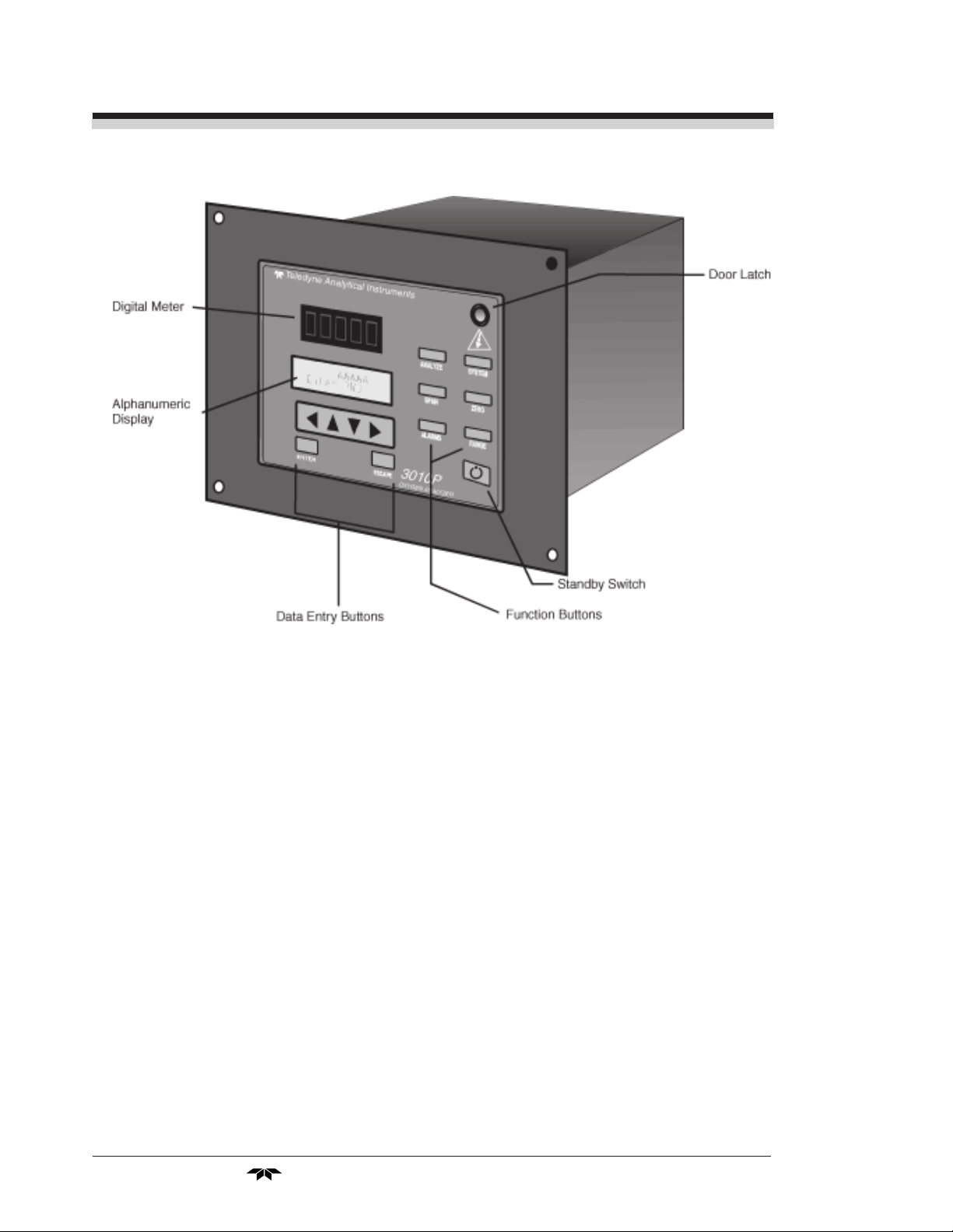
1.2 Control Unit Front Panel
The standard 3010PAC Control Unit is housed in a rugged metal case
with all remote controls and displays accessible from the front panel. See
Figure 1-1. The front panel has a digital meter, an alphanumeric display,
and thirteen buttons for operating the analyzer.
Teledyne Analytical Instruments
Part I: 1-1
Page 14
1 Introduction Model 3010PAC
Figure 1-1: Front of Unmounted Control Unit
Function Keys: Six touch-sensitive membrane switches are used to
change the specific function performed by the analyzer:
• Analyze Perform analysis for oxygen content of a sample gas.
• System Perform system-related tasks (described in detail in
chapter 4, Operation.).
• Span Span calibrate the analyzer.
• Zero Zero calibrate the analyzer.
• Alarms Set the alarm setpoints and attributes.
• Range Set up the 3 user definable ranges for the instrument.
Data Entry Keys: Six touch-sensitive membrane switches are used to
input data to the instrument via the alphanumeric VFD display:
• Left & Right Arrows Select between functions currently
displayed on the VFD screen.
• Up & Down Arrows Increment or decrement values of
functions currently displayed.
1-2: Part I
Teledyne Analytical Instruments
Page 15

Oxygen Anal yzer Part I: Control Unit
• Enter Moves VFD display on to the next screen in a series.
If none remains, returns to the Analyze screen.
• Escape Moves VFD display back to the previous screen in a
series. If none remains, returns to the Analyze screen.
Digital Meter Display: The meter display is a LED device that
produces large, bright, 7-segment numbers that are legible in any lighting.
It is accurate across all analysis ranges from 0-1 % through 0-100 %
Alphanumeric Interface Screen: The backlit VFD screen is an easy-
to-use interface between operator and analyzer. It displays values, options,
and messages that give the operator immediate feedback.
Standby Button: The red I/O button switches the instrument
power between I (ON) and O (a Keep-Alive state). In the O state, the
instrument’s circuitry is operating, but there are no displays or outputs.
CAUTION: The power cable must be unplugged to fully
disconnect power from the instrument. When
chassis is exposed or when access door is open
and power cable is connected, use extra care to
avoid contact with live electrical circuits .
Access Door: For access to the front panel electronics, the front panel
swings open when the latch in the upper right corner of the panel is pressed
all the way in with a narrow gauge tool. Accessing the main circuit board
and other electronics requires unfastening the rear panel screws and sliding
the unit out of the case.
1.3 Recognizing Difference Between LCD & VFD
LCD has GREEN background with BLACK characters. VFD has
DARK background with GREEN characters. In the case of VFD - NO
CONTRAST ADJUSTMENT IS NEEDED.
1.4 Control Unit Rear Panel
The Control Unit rear panel, shown in Figure 1-2, contains the
electrical connectors for external inputs and outputs. The input/output
functions are described briefly here and in detail in the Installation chapter
of this manual.
Teledyne Analytical Instruments
Part I: 1-3
Page 16

1 Introduction Model 3010PAC
Figure 1-2: Model 3010PAC Rear Panel
• Power Connection Universal AC power source.
• Analog Outputs 0-1 V dc concentration and 0-1 V dc
range ID. Optional isolated 4-20 mA dc
and 4-20 mA dc range ID.
• Alarm Connections 2 concentration alarms and 1 system
alarm.
• RS-232 Port Serial digital concentration signal
output and control input.
• Remote Probe Provides all electrical interconnect to
the Analysis Unit or Remote Probe.
• Remote Span/Zero Digital inputs allow external control of
analyzer calibration.
• Calibration Contact To notify external equipment that
instrument is being calibrated and
readings are not monitoring sample.
• Range ID Contacts Four separate, dedicated, range relay
contacts. Low, Medium, High, Cal.
1-4: Part I
Teledyne Analytical Instruments
Page 17

Oxygen Anal yzer Part I: Control Unit
• Remote Probe Interfaces with an Analysis Unit or
Remote Probe (external sensor/sample
system).
• Network I/O Serial digital communications for local
network access. For future expansion.
Not implemented at this printing.
Note: If you require highly accurate Auto-Cal timing, use external
Auto-Cal control where possible. The internal clock in the
Model 3010PAC is accurate to 2-3 %. Accordingly, internally
scheduled calibrations can vary 2-3 % per day.
Teledyne Analytical Instruments
Part I: 1-5
Page 18

1 Introduction Model 3010PAC
1-6: Part I
Teledyne Analytical Instruments
Page 19

Oxygen Anal yzer Part I: Control Unit
Operational Theory
2.1 Introduction
The Model 3010PAC Oxygen Analyzer Control Unit uses an 8031
microcontroller with 32 kB of RAM and 128 kB of ROM to control all
signal processing, input/output, and display functions for the Model
3010PAC analyzer. (The sample system and Micro-Fuel Cell sensor are
covered in Part II, Analysis Unit, in this manual.) System power is supplied
from a universal power supply module designed to be compatible with any
international power source.
2.2 Electronics and Signal Processing
All of the Analyzer electronics are located on Printed Circuit Board
(PCB) assemblies inside the Control Unit chassis. The PCB locations are
illustrated in section 5, Maintenance.
Refer to Figure 2-1, Block Diagram of the 3010PAC CU Electronics:
In the presence of oxygen, the sensor (in the Analysis Unit) generates
a current. A current to voltage amplifier (in the Control Unit) converts this
current to a voltage.
The second stage amplifier amplifies the voltage. It also uses a signal
from the thermistor (which is physically located in the Analysis Unit cell
block) to provide temperature compensation for the sensor signal. The
thermistor is a temperature dependent resistance that changes the gain of
the amplifier in proportion to the temperature changes in the block. This
thermistor signal compensates for the change in the cell output due to the
temperature changes. The result is a signal that is temperature independent.
The output from the second stage amplifier is sent to an 18-bit analog to
digital converter controlled by the microprocessor.
Teledyne Analytical Instruments
Part I: 2-1
Page 20

2 Operational Theory Model 3010PAC
Figure 2-1: Block Diagram of the 3010PAC CU Electronics
2-2: Part I
Teledyne Analytical Instruments
Page 21

Oxygen Anal yzer Part I: Control Unit
The digital concentration signal—along with input from the control
panel—is processed by the microprocessor, and appropriate control signals
are directed to the display, alarms and communications port as well as to
the optional gas control valves in the Analysis Unit.
The same digital information is also sent to a 12 bit digital to analog
converter that produces the 0-1 V dc and the optional 4-20 mA dc analog
concentration signal outputs, and the analog range ID outputs.
The microprocessor monitors the power supply, and activates the
system failure alarm if a malfunction is detected.
Teledyne Analytical Instruments
Part I: 2-3
Page 22

2 Operational Theory Model 3010PAC
2-4: Part I
Teledyne Analytical Instruments
Page 23

Oxygen Anal yzer Part I: Control Unit
Installation
Installation of Model 3010PAC Analyzers includes:
1. Unpacking, mounting, and interconnecting the Control Unit and
the Analysis Unit
2. Making gas connections to the system
3. Making electrical connections to the system
4. Testing the system.
This chapter covers installation of the Control Unit. (Installation of
the Analysis Unit is covered in Part II of this manual.)
3.1 Unpacking the Control Unit
The analyzer is shipped with all the materials you need to install and
prepare the system for operation. Carefully unpack the Control Unit and
inspect it for damage. Immediately report any damage to the shipping
agent.
3.2 Mounting the Control Unit
The Model 3010PAC Control Unit is for indoor use in a general
purpose area. It is NOT for hazardous environments of any type.
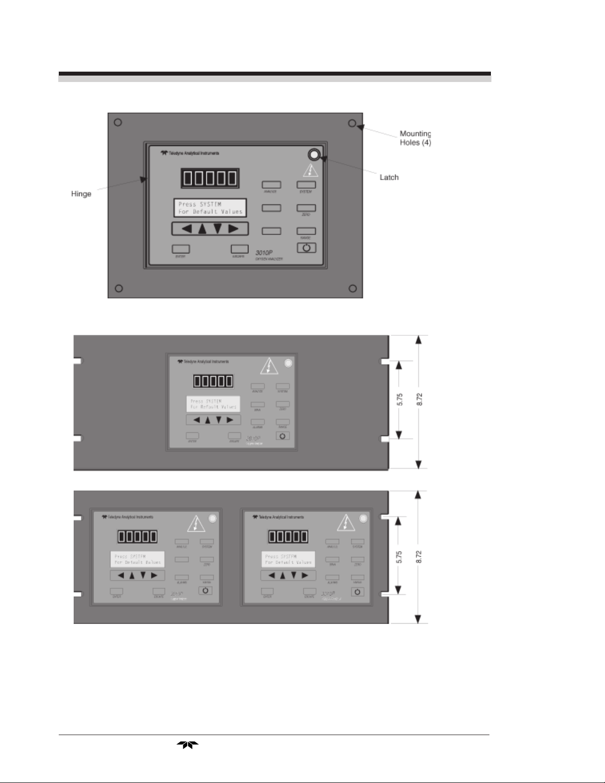
The standard model is designed for flush panel mounting. Figure 3-1
is an illustration of a Model 3010PAC standard Control Unit front panel
and mounting bezel. There are four mounting holes—one in each corner of
the rigid frame. Drawing number D-64596, at the back of this manual,
contains a panel cutout diagram.
On special order, a 19" rack-mounting can be provided. Per order, one
or two 3010PAC series Control Units are flush-panel mounted on the 19"
rack panel. See Figure 3-2.
Part I: 3-1 Teledyne Analytical Instruments
Page 24
3 Installation Model 3010PAC
Figure 3-1: Front Panel of the Model 3010 Control Unit
Figure 3-2: Single and Dual 19" Rack Mounts
All operator controls are mounted on the control panel, which is
hinged on the left edge and doubles as a door to provide access to the
internal components of the instrument. The door is spring loaded and will
swing open when the button in the center of the latch (upper right corner)
3-2: Part I
Teledyne Analytical Instruments
Page 25
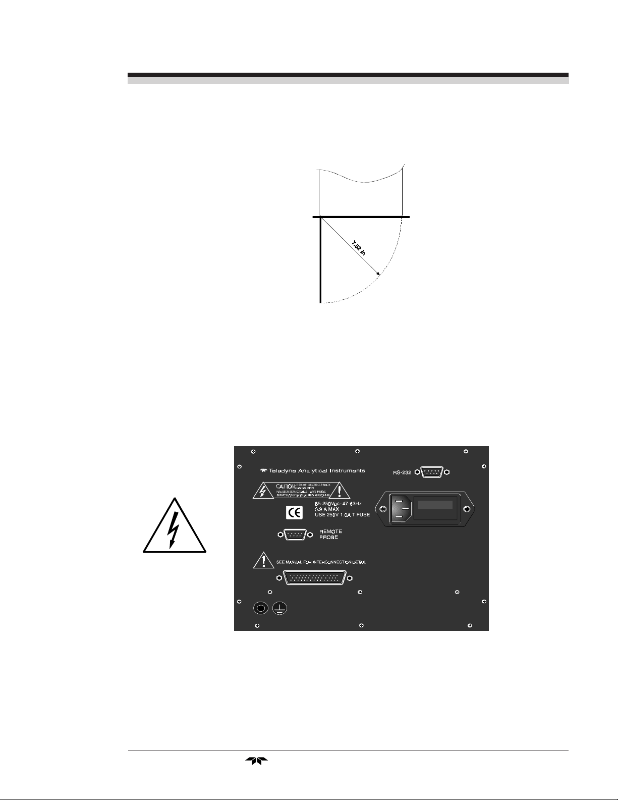
Oxygen Anal yzer Part I: Control Unit
is pressed all the way in with a narrow gauge tool (less than 0.18 inch
wide), such as a small hex wrench or screwdriver Allow clearance for the
door to open in a 90-degree arc of radius 7.625 inches. See Figure 3-3.
Figure 3-3: Required Front Door Clearance
3.3 Electrical Connections
Figure 3-4 shows the Control Unit rear panel. Connections for power,
communications, and both digital and analog signal outputs are described
in the following paragraphs. Wire size and maximum length data appear in
the Drawings in the back of this manual.
Figure 3-4: Rear Panel of the Model 3010PAC Control Unit
For safe connections, no uninsulated wiring should be able to come in
contact with fingers, tools or clothing during normal operation.
Part I: 3-3 Teledyne Analytical Instruments
Page 26

3 Installation Model 3010PAC
CAUTION: Use Shielded Cables. Also, use plugs that provide
excellent EMI/RFI protection. The plug case must
be connected to the cable shield, and it must be
tightly fastened to the analyzer with its fastening
screws. Ultimately, it is the installer who ensures
that the connections provide adequate EMI/RFI
sielding.
3.3.1 Primary Input Power
The universal power supply requires a 85–250 V ac, 47-63 Hz power
source. The power cord receptacle and fuse block are located in the same
assembly. Insert the female plug end of the power cord into the power cord
receptacle.
CAUTION: Power is applied to the instrument's circuitry as
long as the instrument is connected to the power
source. The switch on the front panel is for
switching power on or off to the displays and
outputs only.
Fuse Installation: The fuse block, at the right of the power cord
receptacle, accepts US or European size fuses. A jumper replaces the fuse
in whichever fuse receptacle is not used. Fuses are not installed at the
factory. Be sure to install the proper fuse as part of installation. (See Fuse
Replacement in chapter 5, maintenance.)
3.3.2 50-Pin Equipment Interface Connector
Figure 3-4 shows the pin layout of the Equipment Interface connector.
The arrangement is shown as seen when the viewer faces the rear panel of
the analyzer. The pin numbers for each input/output function are given
where each function is described in the paragraphs below.
Figure 3-4: Equipment Interface Connector Pin Arrangement
3-4: Part I
Teledyne Analytical Instruments
Page 27

Oxygen Anal yzer Part I: Control Unit
Analog Outputs: There are four DC output signal pins—two pins
per output. For polarity, see Table 3-1. The outputs are:
0–1 V dc % of Range: Voltage rises linearly with increasing oxygen,
from 0 V at 0 ppm to 1 V at full scale ppm. (Full
scale = 100% of programmable range.)
0–1 V dc Range ID: 0.25 V = Low Range, 0.5 V = Medium Range,
0.75 V = High Range, 1 V = Air Cal Range.
4–20 mA dc % Range: Current increases linearly with increasing oxygen,
from 4 mA at 0 ppm to 20 mA at full scale ppm.
(Full scale = 100% of programmable range.)
4–20 mA dc Range ID: 8 mA = Low Range, 12 mA = Medium Range, 16
mA = High Range, 20 mA = Air Cal Range.
Table 3-1: Analog Output Connections
Pin Function
3 + Range ID, 4-20 mA, floating
4 – Range ID, 4-20 mA, floating
5 + % Range, 4-20 mA, floating
6 – % Range, 4-20 mA, floating
8 + Range ID, 0-1 V dc
23 – Range ID, 0-1 V dc, negative ground
24 + % Range, 0-1 V dc
7 – % Range, 0-1 V dc, negative ground
Alarm Relays: The three alarm-circuit connectors are spring termi-
nals for making connections to internal alarm relay contacts. Each provides a set of Form C contacts for each type of alarm. Each has both
normally open and normally closed contact connections. The contact
connections are indicated by diagrams on the rear panel. They are capable
of switching up to 3 amperes at 250 V ac into a resistive load. See Figure
3-6. The connectors are:
Threshold Alarm 1: • Can be configured as high (actuates when concen-
tration is above threshold), or low (actuates when
concentration is below threshold).
• Can be configured as failsafe or nonfailsafe.
• Can be configured as latching or nonlatching.
• Can be configured out (defeated).
Threshold Alarm 2: • Can be configured as high (actuates when concen-
tration is above threshold), or low (actuates when
concentration is below threshold).
Part I: 3-5 Teledyne Analytical Instruments
Page 28

3 Installation Model 3010PAC
• Can be configured as failsafe or nonfailsafe.
• Can be configured as latching or nonlatching.
• Can be configured out (defeated).
System Alarm: Actuates when DC power supplied to circuits is
unacceptable in one or more parameters. Permanently configured as failsafe and latching. Cannot be
defeated. Actuates if self test fails.
(Reset by pressing button to remove power. Then
press again and any other button EXCEPT
System to resume.
Further detail can be found in chapter 4, section 4-5.
Table 3-2: Alarm Relay Contact Pins
Pin Contact
45 Threshold Alarm 1, normally closed contact
28 Threshold Alarm 1, moving contact
46 Threshold Alarm 1, normally open contact
42 Threshold Alarm 2, normally closed contact
44 Threshold Alarm 2, moving contact
43 Threshold Alarm 2, normally open contact
36 System Alarm, normally closed contact
20 System Alarm, moving contact
37 System Alarm, normally open contact
Digital Remote Cal Inputs: Accept 0 V (off) or 24 V dc (on) inputs
for remote control of calibration. (See Remote Calibration Protocol below.) See Table 3-3 for pin connections.
Zero: Floating input. 5 to 24 V input across the + and – pins puts
the analyzer into the Zero mode. Either side may be
grounded at the source of the signal. 0 to 1 volt across the
terminals allows Zero mode to terminate when done. A
synchronous signal must open and close the external zero
valve appropriately. See Remote Probe Connector. (The –C
option internal valves operate automatically.)
Span: Floating input. 5 to 24 V input across the + and – pins puts
the analyzer into the Span mode. Either side may be
grounded at the source of the signal. 0 to 1 volt across the
terminals allows Span mode to terminate when done. A
3-6: Part I
Teledyne Analytical Instruments
Page 29

Oxygen Anal yzer Part I: Control Unit
synchronous signal must open and close external span valve
appropriately. See Figure 3-5 Remote Probe Connector.
(The –C option internal valves operate automatically.)
Cal Contact: This relay contact is closed while analyzer is spanning
and/or zeroing. (See Remote Calibration Protocol below.)
Table 3-3: Remote Calibration Connections
Pin Function
9 + Remote Zero
11 – Remote Zero
10 + Remote Span
12 – Remote Span
40 Cal Contact
41 Cal Contact
Remote Calibration Protocol: To properly time the Digital Remote
Cal Inputs to the Model 3010PAC Analyzer, the customer's controller must
monitor the Cal Relay Contact.
When the contact is OPEN, the analyzer is analyzing, the Remote Cal
Inputs are being polled, and a zero or span command can be sent.
When the contact is CLOSED, the analyzer is already calibrating. It
will ignore your request to calibrate, and it will not remember that request.
Once a zero or span command is sent, and acknowledged (contact
closes), release it. If the command is continued until after the zero or span
is complete, the calibration will repeat and the Cal Relay Contact
(CRC) will close again.
For example:
1) Test the CRC. When the CRC is open, Send a zero command
until the CRC closes (The CRC will quickly close.)
2) When the CRC closes, remove the zero command.
3) When CRC opens again, send a span command until the CRC
closes. (The CRC will quickly close.)
4) When the CRC closes, remove the span command.
When CRC opens again, zero and span are done, and the sample is
being analyzed.
Note: The Remote Valve connections (described below) provides
signals to ensure that the zero and span gas valves will be
controlled synchronously. If you have the –C Internal valve
Part I: 3-7 Teledyne Analytical Instruments
Page 30

3 Installation Model 3010PAC
option—which includes additional zero and span gas inputs—
the 3000PAC automatically regulates the zero, span and
sample gas flow.
Range ID Relays: Four dedicated Range ID relay contacts. The
first three ranges are assigned to relays in ascending order—
Low range is assigned to Range 1 ID, Medium range is assigned to Range 2 ID, and High range is assigned to Range 3
ID. The fourth range is reserved for the Air Cal Range (25%).
Table 3-4 lists the pin connections.
Table 3-4: Range ID Relay Connections
Pin Function
21 Range 1 ID Contact
38 Range 1 ID Contact
22 Range 2 ID Contact
39 Range 2 ID Contact
19 Range 3 ID Contact
18 Range 3 ID Contact
34 Range 4 ID Contact (Air Cal)
35 Range 4 ID Contact (Air Cal)
Network I/O: A serial digital input/output for local network protocol.
At this printing, this port is not yet functional. It is to be used for future
options to the instrument. Pins 13 (+) and 29 (–).
Remote Valve Connections: The 3010PAC is a single-chassis
instrument, which has no Remote Valve Unit. Instead, the Remote Valve
connections are used as a method for directly controlling external sample/
zero/span gas valves. See Figure 3-5.
Figure 3-5: Remote Probe Connections
3-8: Part I
Teledyne Analytical Instruments
Page 31

Oxygen Anal yzer Part I: Control Unit
The voltage from these outputs is nominally 0 V for the OFF and
15 V dc for the ON conditions. The maximum combined current that can
be pulled from these output lines is 100 mA. (If two lines are ON at the
same time, each must be limited to 50 mA, etc.) If more current and/or a
different voltage is required, use a relay, power amplifier, or other matching circuitry to provide the actual driving current.
In addition, each individual line has a series FET with a nominal ON
resistance of 5 ohms (9 ohms worst case). This can limit the obtainable
voltage, depending on the load impedance applied. See Figure 3-6.
Figure 3-6: FET Series Resistance
3.3.3 RS-232 Port
The digital signal output is a standard, full duplex RS-232 serial
communications port used to connect the analyzer to a computer, terminal,
or other digital device. It requires a standard 9-pin D connector.
The output data is status information, in digital form, updated every
two seconds. Status is reported in the following order:
• The concentration in ppm or percent
• The range in use (HI, MED, LO)
• The span of the range (0-100 ppm, etc)
• Which alarms—if any—are disabled (AL–x DISABLED)
• Which alarms—if any—are tripped (AL–x ON).
Each status output is followed by a carriage return and line feed.
Three input functions using RS-232 have been implemented to date.
They are described in Table 3-5.
Part I: 3-9 Teledyne Analytical Instruments
Page 32

3 Installation Model 3010PAC
Table 3-5: Commands via RS-232 Input
Command Description
as<enter> Immediately starts an autospan.
az<enter> Immediately starts an autozero.
st<enter> Toggling input. Stops/Starts any status message output
from the RS-232, until st<enter> is sent again.
The RS-232 protocol allows some flexibility in its implementation.
Table 3-6 lists certain RS-232 values that are required by the 3010PAC
implementation.
Table 3-6: Required RS-232 Options
Parameter Setting
Baud 2400
Byte 8 bits
Parity none
Stop Bits 1
Message Interval 2 seconds
3.3.4 Remote Probe Connection
The Models 3010PAC are split architecture (dual-chassis) instruments, which have a Remote Probe, or Analysis Unit. The remote probe is
for receiving the oxygen sensor and thermistor signals. See Figure 3-7 for
remote probe connection. The connections of the Analysis Unit are covered
in detail in Part II, section 3.4, of this manual.
Remote Probe 9-pin Connector
8
5
6
1
Sensor Hot
Sensor Return
Thermistor Return
Thernistor Hot
Figure 3-7: Remote Probe Interface PinoutTable 3-1:
3-10: Part I
Teledyne Analytical Instruments
Page 33

Oxygen Anal yzer Part I: Control Unit
CAUTION: If you use your own control valves, or any other
design, please be aware that the Intrinsic Safe
requirements are provided. (See drawing D-66191
for wire recommendations).
3.4 Testing the System
After The Control Unit and the Analysis Unit are both installed and
interconnected, and the system gas and electrical connections are complete,
the system is ready to test. Before plugging either of the units into their
respective power sources:
• Check the integrity and accuracy of the gas connections. Make
sure there are no leaks.
• Check the integrity and accuracy of all electrical connections.
Make sure there are no exposed conductors
Power up the system, and test it by performing the following
operations:
1. Repeat the Self-Diagnostic Test as described in chapter 4,
section 4.3.5.
Part I: 3-11 Teledyne Analytical Instruments
Page 34

3 Installation Model 3010PAC
3-12: Part I
Teledyne Analytical Instruments
Page 35

Oxygen Anal yzer Part I: Control Unit
Operation
4.1 Introduction
Once the analyzer has been installed, configure it for your process. To
do this you can:
• Set system parameters—
• Specify a password, if desired, requiring operator to log in.
• Establish and start an automatic calibration cycle, if desired.
• Calibrate the instrument.
• Define the three user selectable analysis ranges. Then choose
autoranging or select a fixed range of analysis, as required.
• Set alarm setpoints, and modes (latching, failsafe, etc).
Before configuration these default values are in effect:
PARAMETER DEFAULT
LO Range 1%
MED Range 5%
HI Range 10 %
Auto Ranging ON
Alarm Relays 10 %
(Defeated, HI, Not failsafe, Not latching)
Span 20.9 %
(Auto, every 0 days at 0 hours)
Zero (Auto, every 0 days at 0 hours).
If you choose not to use password protection, the default password is
automatically displayed on the password screen when you start up, and you
simply press Enter for access to all functions of the analyzer.
Teledyne Analytical Instruments
Part I: 4-1
Page 36

4 Operation Model 3010PAC
4.2 Using the Data Entry and Function
Buttons
Data Entry Buttons: The < > arrow buttons select options from the
menu currently being displayed on the VFD screen. The selected option
blinks.
When the selected option includes a modifiable item, the
buttons can be used to increment or decrement that modifiable item.
The Enter button is used to accept any new entries on the VFD screen.
The Escape button is used to abort any new entries on the VFD screen that
are not yet accepted by use of the Enter button.
Figure 4-1 shows the hierarchy of functions available to the operator via
the function buttons. The six function buttons on the analyzer are:
• Analyze. This is the normal operating mode. The analyzer
monitors the oxygen content of the sample, displays the
concentration of oxygen, and warns of any alarm conditions.
• System. The system function consists of six subfunctions that
regulate the internal operations of the analyzer:
• LCD screen contrast
• Auto-Cal setup
• Password assignment
• Self -Test initiation
• Checking software version
• Logging out.
Contrast Function is DISABLED
(Refer to Section 1.3)
∆∆
∆∇ arrow
∆∆
• Zero. Used to set up a zero calibration.
• Span. Used to set up a span calibration.
• Alarms. Used to set the alarm setpoints and determine whether
each alarm will be active or defeated, HI or LO acting, latching,
and/or failsafe.
• Range. Used to set up three analysis ranges that can be switched
automatically with autoranging or used as individual fixed
ranges.
Any function can be selected at any time by pressing the appropriate
button (unless password restrictions apply). The order as presented in this
manual is appropriate for an initial setup.
4-2: Part I
Teledyne Analytical Instruments
Page 37

Oxygen Anal yzer Part I: Control Unit
Contrast Function is DISABLED
(Refer to Section 1.3)
Figure 4-1: Hierarchy of Functions and Subfunctions
Each of these functions is described in greater detail in the following
procedures. The VFD screen text that accompanies each operation is reproduced, at the appropriate point in the procedure, in a Monospaced type
style. Pushbutton names are printed in Oblique type.
4.3 The System Function
The subfunctions of the System function are described below. Specific
procedures for their use follow the descriptions:
• Auto-Cal: Used to define an automatic calibration sequence
and/or start an Auto-Cal.
• PSWD: Security can be established by choosing a 5 digit
password (PSWD) from the standard ASCII character set. (See
Installing or Changing a Password, below, for a table of ASCII
characters available.) Once a unique password is assigned and
Teledyne Analytical Instruments
Part I: 4-3
Page 38

4 Operation Model 3010PAC
activated, the operator MUST enter the UNIQUE password to
gain access to set-up functions which alter the instrument's
operation, such as setting the instrument span or zero setting,
adjusting the alarm setpoints, or defining analysis ranges.
After a password is assigned, the operator must log out to
activate it. Until then, anyone can continue to operate the
instrument without entering the new password.
Only one password can be defined. Before a unique password
is assigned, the system assigns TBEAI by default. This allows
access to anyone. After a unique password is assigned, to defeat
the security, the password must be changed back to TBEAI.
• Logout: Logging out prevents an unauthorized tampering with
analyzer settings.
• More: Select and enter More to get a new screen with additional
subfunctions listed.
• Self–Test: The instrument performs a self-diagnostic test to
check the integrity of the power supply, output boards and
amplifiers.
• Version: Displays Manufacturer, Model, and Software Version
of instrument.
4.3.1 Setting the Display
Contrast Function is DISABLED
(Refer to Section 1.3)
If you cannot read anything on the display after first powering up:
1. Observe LED readout.
a. If LED meter reads all eights and points, go to step 3.
b. If LED meter displays anything else, go to step 2.
2. Press button twice to turn Analyzer OFF and ON again. LED
meter should now read all eights and periods.
4-4: Part I
Teledyne Analytical Instruments
Page 39

Oxygen Anal yzer Part I: Control Unit
4.3.2 Setting up an Auto-Cal
When the proper calibration gases are connected (see chapter 3, instal-
lation), the Analyzer can cycle itself through a sequence of steps that auto-
matically zero and span the instrument.
Note: If you require highly accurate Auto-Cal timing, use external
Auto-Cal control where possible. The internal clock in the
Model 3010PAC is accurate to 2-3 %. Accordingly, internally
scheduled calibrations can vary 2-3 % per day.
To setup an Auto–Cal cycle:
Choose System from the Function buttons. The LCD will display five
subfunctions.
Contrast Function is DISABLED
(Refer to Section 1.3)
Contrast Auto—Cal
PSWD Logout More
Use < > arrows to blink Auto—Cal, and press Enter. A new screen for
Span/Zero set appears.
Span OFF Nxt: 0d 0h
Zero OFF Nxt: 0d 0h
Press < > arrows to blink Span (or Zero), then press Enter again. (You
won’t be able to set OFF to ON if a zero interval is entered.) A Span
Every ... (or Zero Every ...) screen appears.
Span Every 0 d
Start 0 h from now
∆∆
Use
∆∇ arrows to set an interval value, then use < > arrows to move to
∆∆
the start-time value. Use
∆∆
∆∇ arrows to set a start-time value.
∆∆
To turn ON the Span and/or Zero cycles (to activate Auto-Cal): Press
System again, choose Auto—Cal, and press Enter again. When the Span/
Zero values screen appears, use the < > arrows to blink the Span (or Zero)
OFF/ON field. Use
∆∆
∆∇ arrows to set the OFF/ON field to ON. You can
∆∆
now turn these fields ON because there is a nonzero span interval defined.
4.3.3 Password Protection
If a password is assigned, then setting the following system parameters
can be done only after the password is entered: span and zero settings,
alarm setpoints, analysis range definitions, switching between autoranging
and manual override, setting up an auto-cal, and assigning a new password.
However, the instrument can still be used for analysis or for initiating a selftest without entering the password.
Teledyne Analytical Instruments
Part I: 4-5
Page 40

4 Operation Model 3010PAC
If you have decided not to employ password security, use the default
password TBEAI. This password will be displayed automatically by the
microprocessor. The operator just presses the Enter key to be allowed total
access to the instrument’s features.
NOTE: If you use password security, it is advisable to keep a copy of
the password in a separate, safe location.
4.3.3.1 Entering the Password
To install a new password or change a previously installed password,
you must key in and ENTER the old password first. If the default password
is in effect, pressing the ENTER button will enter the default TBEAI
password for you.
Press System to enter the System mode.
Contrast Auto—Cal
PSWD Logout More
Contrast Function is DISABLED
(Refer to Section 1.3)
Use the < > arrow keys to scroll the blinking over to PSWD, and press
Enter to select the password function. Either the default TBEAI password or
AAAAA place holders for an existing password will appear on screen
depending on whether or not a password has been previously installed.
T B E A I
Enter PWD
or
A A A A A
Enter PWD
The screen prompts you to enter the current password. If you are not
using password protection, press Enter to accept TBEAI as the default
password. If a password has been previously installed, enter the password
using the < > arrow keys to scroll back and forth between letters, and the
∆∆
∆∇
∆∆
arrow keys to change the letters to the proper password. Press Enter to enter
the password.
If the password is accepted, the screen will indicate that the password
restrictions have been removed and you have clearance to proceed.
In a few seconds, you will be given the opportunity to change this
password or keep it and go on.
4-6: Part I
PSWD Restrictions
Removed
Teledyne Analytical Instruments
Page 41

Oxygen Anal yzer Part I: Control Unit
Change Password?
<ENT>=Yes <ESC>=No
Press Escape to move on, or proceed as in Changing the Password,
below.
4.3.3.2 Installing or Changing the Password
If you want to install a password, or change an existing password,
proceed as above in Entering the Password. When you are given the opportunity to change the password:
Change Password?
<ENT>=Yes <ESC>=No
Press Enter to change the password (either the default TBEAI or the
previously assigned password), or press Escape to keep the existing password and move on.
If you chose Enter to change the password, the password assignment
screen appears.
T B E A I
<ENT> To Proceed
or
A A A A A
<ENT> To Proceed
Enter the password using the < > arrow keys to move back and forth
between the existing password letters, and the
∆∆
∆∇ arrow keys to change the
∆∆
letters to the new password. The full set of 94 characters available for password use are shown in the table below.
Characters Available for Password Definition:
ABCDEFGHIJ
KLMNOPQRST
UVWXYZ[¥]^
_`abcdefgh
ijklmnopqr
stuvwxyz{|
} → !"#$%&'(
)*+'-./012
3456789:;<
=>?@
Teledyne Analytical Instruments
Part I: 4-7
Page 42

4 Operation Model 3010PAC
When you have finished typing the new password, press Enter. A
verification screen appears. The screen will prompt you to retype your
password for verification.
A A A A A
Retype PWD To Verify
Wait a moment. The entry screen will give you clearance to proceed.
A A A A A
<ENT> TO Proceed
Use the arrow keys to retype your password and press Enter when
finished. Your password will be stored in the microprocessor and the system
will immediately switch to the Analyze screen, and you now have access to
all instrument functions.
If no alarms are tripped, the Analyze screen appears as:
0.0 % AnlZ
Range: 0 — 100
If an alarm is tripped, the second line will change to show which alarm
it is:
0.0 % Anlz
AL—1
NOTE:If you previously logged off the system , you will now be
required to re-enter the password to gain access to Span,
Zero, Alarm, and Range functions.
4.3.4 Logout
The Logout function provides a convenient means of leaving the
analyzer in a password protected mode without having to shut the instrument
off. By entering Logout, you effectively log off the instrument leaving the
system protected against use until the password is reentered. To log out,
press the System button to enter the System function.
Contrast Auto—Cal
PSWD Logout More
Contrast Function is DISABLED
(Refer to Section 1.3)
Use the < > arrow keys to position the blinking over the Logout function, and press Enter to Log out. The screen will display the message:
Protected Until
Password Reentered
4-8: Part I
Teledyne Analytical Instruments
Page 43

Oxygen Anal yzer Part I: Control Unit
4.3.5 System Self-Diagnostic Test
The Model 3010PAC has a built-in self-diagnostic testing routine. Preprogrammed signals are sent through the power supply, output board and
sensor circuit. The return signal is analyzed, and at the end of the test the
status of each function is displayed on the screen, either as OK or as a
number between 1 and 3. (See System Self Diagnostic Test in chapter 5 for
number code.)
Note: Remote Probe connector must be connected to the Analysis
Unit, or sensor circuit will not be properly checked.
The self diagnostics are run automatically by the analyzer whenever the
instrument is turned on, but the test can also be run by the operator at will.
To initiate a self diagnostic test during operation:
Press the System button to start the System function.
Contrast Function is DISABLED
(Refer to Section 1.3)
Contrast Auto—Cal
PSWD Logout More
Use the < > arrow keys to blink More, then press Enter.
Version Self—Test
Use the < > arrow keys again to move the blinking to the Self–Test
function. The screen will follow the running of the diagnostic.
RUNNING DIAGNOSTIC
Testing Preamp — 83
During preamp testing there is a countdown in the lower right corner of
the screen. When the testing is complete, the results are displayed.
Power: OK Analog: OK
Preamp: 3
The module is functioning properly if it is followed by OK. A number
indicates a problem in a specific area of the instrument. Refer to chapter 5
Maintenance for number-code information. The results screen alternates for a
time with:
Press Any Key
To Continue...
Then the analyzer returns to the initial System screen.
Teledyne Analytical Instruments
Part I: 4-9
Page 44

4 Operation Model 3010PAC
4.3.6 Version Screen
Move the < > arrow key to More and press Enter. With Version
blinking, press Enter. The screen displays the manufacturer, model, and
software version information.
4.4 The Span Functions
The analyzer is calibrated using span gas.
NOTE: Zero is not necessary for Percent (%) level measurements.
Additional information on Zero functions is provided in the
Appendix A-5 of this manual.
Although the instrument can be spanned using air, a span gas with a
known oxygen concentration in the range of 70–90% of full scale of the
range of interest is recommended. Since the oxygen concentration in air is
20.9 %, the cell can take longer to recover if the instrument is used for very
low levels, such as 1% full scale oxygen analysis, immediately following
calibration in air.
Connect the calibration gases to the analyzer according to the instructions given in Section 3.4.1, Gas Connections, observing all the prescribed
precautions.
If you are using password protection, you will need to enter your
password to gain access to either of these functions. Follow the instructions
in sections 4.3.3.2 or 4.3.3.3 to enter your password. Once you have gained
clearance to proceed, you can enter the Zero or Span function.
4.4.1. Cell Failure
When the sensor in the 3010PAC begins to fail, the analyzer will
usually require more and more frequent calibration. If the 3010PAC analysis
readings drift downward uncharacteristically, try recalibration. If recalibration raises the readings temporarily, the cell may be failing.
You can check the output of the cell itself by going to the System
function, selecting More, and pressing Enter. The cell output reading will be
on the second line of the display.
4-10: Part I
Teledyne Analytical Instruments
Page 45

Oxygen Anal yzer Part I: Control Unit
Version Self—Test
Cell Output: ### µA
The “good” reading depends on the class of cell your analyzer is using.
Although the B-1 cell is standard in the 3010PAC, check Specific Model
Information in the Front Matter in this manual for the class of cell you
purchased.
Then check Cell Replacement in Part II Analysis Units, chapter 5
Maintenance, and do the prescribed calculations. If a weak cell is indicated,
replace the cell as described there in chapter 5.
4.4.2 Span Cal
The Span button on the front panel is used to span calibrate the ana-
lyzer. Span calibration can be performed using the automatic mode, where
an internal algorithm compares consecutive readings from the sensor to
determine when the output matches the span gas concentration. Span calibration can also be performed in manual mode, where the operator determines when the span concentration reading is acceptable and manually exits
the function.
4.4.2.1 Auto Mode Spanning
Press Span to enter the span function. The screen that appears allows
you to select whether the span calibration is to be performed automatically or
manually. Use the
∆∆
∆∇ arrow keys to toggle between AUTO and MAN span
∆∆
settling. Stop when AUTO appears, blinking, on the display.
Span: Settling: AUTO
<ENT> For Next
Press Enter to move to the next screen.
Span Val: 20.90
<ENT>Span <UP>Mod #
Use the
the < > arrow keys to blink the digit you are going to modify. Use the
∆∆
∆∇ arrow keys to enter the oxygen-concentration mode. Use
∆∆
∆∆
∆∇
∆∆
arrow keys again to change the value of the selected digit. When you have
finished typing in the concentration of the span gas you are using (20.90 if
you are using air), press Enter to begin the Span calibration.
#### % Span
Slope=#### ppm/s
The beginning span value is shown in the upper left corner of the
display. As the span reading settles, the screen displays and updates informa-
Teledyne Analytical Instruments
Part I: 4-11
Page 46

4 Operation Model 3010PAC
tion on Slope. Spanning automatically ends when the span output corresponds, within tolerance, to the value of the span gas concentration. Then the
instrument automatically returns to the analyze mode.
4.4.2.2 Manual Mode Spanning
Press Span to start the Span function. The screen that appears allows
you to select whether the span calibration is to be performed automatically or
manually.
Span: Settling:MAN
<ENT> For Next
Use the ∆∇ keys to toggle between AUTO and MAN span settling.
Stop when MAN appears, blinking, on the display. Press Enter to move to
the next screen.
Span Val: 20.90
<ENT>Span <UP>Mod #
Press ∆ (<UP>) to permit modification (Mod #) of span value.
Use the arrow keys to enter the oxygen concentration of the span gas
you are using (20.90 if you are using air). The < > arrows choose the digit,
and the ∆∇ arrows choose the value of the digit.
Press Enter to enter the span value into the system and begin the span
calibration.
Once the span has begun, the microprocessor samples the output at a
predetermined rate. It calculates the difference between successive samplings
and displays this difference as Slope on the screen. It takes several seconds
for the first Slope value to display. Slope indicates rate of change of the Span
reading. It is a sensitive indicator of stability.
#### % Span
Slope=#### ppm/s
When the Span value displayed on the screen is sufficiently stable,
press Enter. (Generally, when the Span reading changes by 1 % or less of
the full scale of the range being calibrated for a period of ten minutes it is
sufficiently stable.) Once Enter is pressed, the Span reading changes to the
correct value. The instrument then automatically enters the Analyze function.
4-12: Part I
Teledyne Analytical Instruments
Page 47

Oxygen Anal yzer Part I: Control Unit
4.5 The Alarms Function
The Model 3010PAC is equipped with 2 fully adjustable concentration
alarms and a system failure alarm. Each alarm has a relay with a set of form
C contacts rated for 3 amperes resistive load at 250 V ac. See figure in
chapter 3, Installation and/or the Interconnection Diagram included at the
back of this manual for relay terminal connections.
The system failure alarm has a fixed configuration described in chapter
3 Installation.
The concentration alarms can be configured from the front panel as
either high or low alarms by the operator. The alarm modes can be set as
latching or nonlatching, and either failsafe or nonfailsafe, or, they can be
defeated altogether. The setpoints for the alarms are also established using
this function.
Decide how your alarms should be configured. The choice will depend
upon your process. Consider the following four points:
1. Which if any of the alarms are to be high alarms and which if any
are to be low alarms?
Setting an alarm as HIGH triggers the alarm when the oxygen
concentration rises above the setpoint. Setting an alarm as LOW
triggers the alarm when the oxygen concentration falls below the
setpoint.
Decide whether you want the alarms to be set as:
• Both high (high and high-high) alarms, or
• One high and one low alarm, or
• Both low (low and low-low) alarms.
2. Are either or both of the alarms to be configured as failsafe?
In failsafe mode, the alarm relay de-energizes in an alarm
condition. For nonfailsafe operation, the relay is energized in an
alarm condition. You can set either or both of the concentration
alarms to operate in failsafe or nonfailsafe mode.
3. Are either of the alarms to be latching?
In latching mode, once the alarm or alarms trigger, they will
remain in the alarm mode even if process conditions revert back
to no-alarm conditions. This mode requires an alarm to be
recognized before it can be reset. In the nonlatching mode, the
alarm status will terminate when process conditions revert to noalarm conditions.
4. Are either of the alarms to be defeated?
Teledyne Analytical Instruments
Part I: 4-13
Page 48

4 Operation Model 3010PAC
The defeat alarm mode is incorporated into the alarm circuit so
that maintenance can be performed under conditions which
would normally activate the alarms.
The defeat function can also be used to reset a latched alarm.
(See procedures, below.)
If you are using password protection, you will need to enter your
password to access the alarm functions. Follow the instructions in Section
4.3.3 to enter your password. Once you have clearance to proceed, enter the
Alarm function.
Press the Alarm button on the front panel to enter the Alarm function.
Make sure that AL–1 is blinking.
AL—1 AL—2
Choose Alarm
Set up alarm 1 by moving the blinking over to AL–1 using the < >
arrow keys. Then press Enter to move to the next screen.
AL—1 10 % HI
Dft—N Fs—N Ltch—N
Five parameters can be changed on this screen:
• Value of the alarm setpoint, AL–1 #### (% oxygen)
• Out-of-range direction, HI or LO
• Defeated? Dft–Y/N (Yes/No)
• Failsafe? Fs–Y/N (Yes/No)
• Latching? Ltch–Y/N (Yes/No).
• To define the setpoint, use the < > arrow keys to move the
blinking over to AL–1 ####. Then use the ∆∇ arrow keys to
change the number. Holding down the key speeds up the
incrementing or decrementing. (Remember, setpoint units are
parts-per-million.)
• To set the other parameters use the < > arrow keys to move the
blinking over to the desired parameter. Then use the ∆∇ arrow
keys to change the parameter.
• Once the parameters for alarm 1 have been set, press Alarms
again, and repeat this procedure for alarm 2 (AL–2).
• To reset a latched alarm, go to Dft– and then press either ∆ two
4-14: Part I
times or ∇ two times. (Toggle it to Y and then back to N.)
–OR –
Teledyne Analytical Instruments
Page 49

Oxygen Anal yzer Part I: Control Unit
Go to Ltch– and then press either ∆ two times or ∇ two times.
(Toggle it to N and back to Y.)
4.6 The Range Function
The Range function allows the operator to program up to three concentration ranges to correlate with the DC analog outputs. If no ranges are
defined by the user, the instrument defaults to:
Range Limits
Low 0–1 %
Med 0–5 %
High 0–10 %.
The Model 3010PAC is set at the factory to default to autoranging. In
this mode, the microprocessor automatically responds to concentration
changes by switching ranges for optimum readout sensitivity. If the current
range limits are exceeded, the instrument will automatically shift to the next
higher range. If the concentration falls to below 85% of full scale of the next
lower range, the instrument will switch to that range. A corresponding shift
in the DC percent-of-range output, and in the range ID outputs, will be
noticed.
The autoranging feature can be overridden so that analog output stays
on a fixed range regardless of the oxygen concentration detected. If the
concentration exceeds the upper limit of the range, the DC output will
saturate at 1 V dc (20 mA at the current output).
However, the digital readout and the RS-232 output of the concentration are unaffected by the fixed range. They continue to read accurately with
full precision. See Front Panel description in chapter 1.
The automatic air calibration range is always 0-25 % and is not programmable.
4.6.1 Setting the Analog Output Ranges
To set the ranges, enter the range function mode by pressing the
Range button on the front panel.
L—### M—####
H—##### Mode—AUTO
Use the < > arrow keys to blink the range to be set: low (L), medium
(M), or high (H).
Teledyne Analytical Instruments
Part I: 4-15
Page 50

4 Operation Model 3010PAC
Use the ∆∇ arrow keys to enter the upper value of the range (all ranges
begin at 0 %). Repeat for each range you want to set. Press Enter to accept
the values and return to Analyze mode. (See note below.)
Note: The ranges must be increasing from low to high, for example,
if range 1 is set for 0–10 % and range 2 is set for 0–100 %,
range 3 cannot be set for 0–50 % since it is lower than range 2.
4.6.2 Fixed Range Analysis
The autoranging mode of the instrument can be overridden, forcing the
analyzer DC outputs to stay in a single predetermined range.
To switch from autoranging to fixed range analysis, enter the range
function by pressing the Range button on the front panel.
Use the < > arrow keys to move the blinking over AUTO.
Use the ∆∇ arrow keys to switch from AUTO to FX/LO, FX/MED, or
FX/HI to set the instrument on the desired fixed range (low, medium, or
high).
L—### M—####
H—##### Mode—FX/LO
or
L—### M—####
H—##### Mode—FX/MED
or
L—### M—####
H—##### Mode—FX/HI
Press Escape to re-enter the Analyze mode using the fixed range.
NOTE:When performing analysis on a fixed range, if the oxygen
concentration rises above the upper limit (or default value) as
established by the operator for that particular range, the
output saturates at 1 V dc (or 20 mA). However, the digital
readout and the RS-232 output continue to read the true value
of the oxygen concentration regardless of the analog output
range.
4-16: Part I
Teledyne Analytical Instruments
Page 51

Oxygen Anal yzer Part I: Control Unit
4.7 The Analyze Function
When the Analyze function is active, the 3010PAC is monitoring the
sample gas currently flowing in the Analysis Unit cell block. All undefeated
alarms are ready to activate should their respective setpoints be crossed.
Press the Analyze button to put the analyzer in the Analyze mode.
Normally, all of the functions automatically switch back to the Analyze
function when they have completed their assigned operations. Pressing the
Escape button in many cases also switches the analyzer back to the Analyze function. Alternatively, you can press the Analyze button at any time
to return to analyzing your sample.
4.8 Signal Output
The standard Model 3010PAC Oxygen Analyzer are equipped with
two 0-1 V dc analog output terminals accessible on the back panel (one
concentration and one range ID). Two isolated 4-20 mA dc current outputs
(one concentration and one range ID), in addition to the voltage outputs, are
optional.
See Rear Panel in chapter 3, Installation, for illustration.
The signal output for concentration is linear over the currently selected
analysis range. For example, if the analyzer is set on range that was defined
as 0–10 % O2, then the output would be:
Voltage Signal Current Signal
% O
2
0 0.0 4.0
1 0.1 5.6
2 0.2 7.2
3 0.3 8.8
4 0.4 10.4
5 0.5 12.0
6 0.6 13.6
7 0.7 15.2
8 0.8 16.8
9 0.9 18.4
10 1.0 20.0
Output (V dc) Output (mA dc)
Teledyne Analytical Instruments
Part I: 4-17
Page 52

4 Operation Model 3010PAC
Interpretation of the analog output signal depends on the voltage (or
current) AND the currently activated analysis range. To relate the signal
output to the actual concentration, it is necessary to know what range the
instrument is currently on, especially when the analyzer is in the autoranging
mode.
To provide an indication of the range, a second pair of analog output
terminals are used. They generate a steady preset voltage (or current when
using the current outputs) to represent a particular range. The following table
gives the range ID output for each analysis range:
Range Voltage (V) Current (mA)
LO 0.25 8
MED 0.50 12
HI 0.75 16
CAL (0-25%) 1.00 20
4-18: Part I
Teledyne Analytical Instruments
Page 53

Part I: Control Unit Maintenance 5
Maintenance
Aside from normal cleaning and checking for leaks at the gas connections, routine maintenance is limited to replacing Micro-Fuel cells and
fuses, and recalibration.
Checking for leaks, replacing Micro-Fuel cells, and replacing fuses in
the Analysis Unit are covered in Part II, Chapter 5. For recalibration, see
Part I, section 4.4 Calibration.
WARNING: SEE WARNINGS ON THE TITLE PAGE OF THIS
MANUAL.
5.1 Fuse Replacement
1. Place small screwdriver in notch, and pry cover off, as shown in
Figure 5-1.
Figure 5-1: Removing Fuse Block from Housing
2. To change between American and European fuses, remove the
single retaining screw, flip Fuse Block over 180 degrees, and
replace screw.
Teledyne Analytical Instruments
Part I: 5-1
Page 54

5 Maintenance Model 3010PAC Oxygen Analyzer
3. Replace fuse as shown in Figure 5-2.
4. Reassemble Housing as shown in Figure 5-1.
American Fuses European Fuses
Figure 5-2: Installing Fuses
5.2 System Self Diagnostic Test
1. Press the System button to enter the system mode.
2. Use the < > arrow keys to move to More, and press Enter.
3. Use the < > arrow keys to move to Self-Test, and press Enter.
The following failure codes apply:
Table 5-1: Self Test Failure Codes
Power
0OK
1 5 V Failure
2 15 V Failure
3 Both Failed
Analog
0OK
1 DAC A (0–1 V Concentration)
2 DAC B (0–1 V Range ID)
3 Both Failed
Preamp
0OK
1 Zero too high
2 Amplifier output doesn't match test input
3 Both Failed
5-2: Part I
Teledyne Analytical Instruments
Page 55

Part I: Control Unit Maintenance 5
5.3 Major Internal Components
The major components in the Control Unit are shown in Figure 5-3.
Figure 5-3: Control Unit Major Internal Components
WARNING: HAZARDOUS VOLTAGES EXIST ON CERTAIN COM-
PONENTS INTERNALLY WHICH MAY PERSIST FOR
A TIME EVEN AFTER THE POWER IS TURNED OFF
AND DISCONNECTED.
The 3010PAC Control Units contain the following major components:
• Power Supply
• Motherboard (with Microprocessor, RS-232 chip, and
Preamplifier PCB)
• Front Panel Display Board and Displays—
5 digit LED meter
2 line, 20 character, alphanumeric,VFD display
See the drawings in the Drawings section in back of this manual
for details.
The Front Panel Display Board is accessed by unlatching and swinging open the front panel, as described earlier. Other electronic components
are accessed by removing four rear panel screws and sliding out the entire
chassis. See Figure 5-4, below.
Teledyne Analytical Instruments
Part I: 5-3
Page 56

5 Maintenance Model 3010PAC Oxygen Analyzer
xx
x
xx
x
xx
xx
x
xx
Figure 5-4: Rear-Panel Screws
xx
xx
x
xx
To detach the rear panel, remove only those four screws marked with an
X.
5.4 Cleaning
If instrument is unmounted at time of cleaning, disconnect the instrument from the power source. Close and latch the front-panel access door.
Clean outside surfaces with a soft cloth dampened slightly with plain clean
water. Do not use any harsh solvents such as paint thinner or benzine.
For panel-mounted instruments, clean the front panel as prescribed in
the above paragraph. DO NOT wipe front panel while the instrument is
monitoring your process.
5-4: Part I
Teledyne Analytical Instruments
Page 57

Part II: Analysis Unit
OPERATING INSTRUCTIONS
Model 3010PAC
Oxygen Analyzer
Part II
Intrinsic Safe Barriers
and
Remote Probe
CENELEC Type
Part Number C-66426
Teledyne Analytical Instruments
Part II: i
Page 58

Model 3010PAC Oxygen Analyzer
Table of Contents
1 Introduction
1.1 Overview ........................................................................ 1-1
1.2 Intrinsic Safe Barriers ..................................................... 1-1
1.3 Area Clasificationl .......................................................... 1-2
1.4 Cell Housing/Probe ........................................................ 1-2
2 Operational Theory
2.1 Introduction .................................................................... 2-1
2.2 Micro-Fuel Cell Sensors................................................. 2-1
2.2.1 Principles of Operation........................................... 2-1
2.2.2 Anatomy of a Micro-Fuel Cell ................................ 2-2
2.2.3 Electrochemical Reactions..................................... 2-3
2.2.4 The Effect of Pressure........................................... 2-4
2.2.5 Calibration Characteristics ..................................... 2-4
2.2.6 Micro-Fuel Cell “Class”........................................... 2-5
2.2.6.1 Class A-3 Cell............................................ 2-5
2.2.6.2 Class A-5 Cell............................................ 2-5
2.2.6.3 Class B-1 Cell............................................ 2-6
2.2.6.4 Class B-3 Cell............................................ 2-6
2.2.6.5 Class C-3 Cell............................................ 2-6
2.2.6.6 Hydrogen and/or Helium Service................ 2-6
3 Installation
3.1 Unpacking the Analysis Unit........................................... 3-1
3.2 Mounting the Analysis Unit ............................................. 3-1
3.3 Installing the Micro-Fuel Cell .......................................... 3-2
3.4 T esting the System ......................................................... 3-2
3.5 Intrinsic Safety Barriers................................................... 3-3
3.6 Remote Probe Connection ............................................. 3-5
4 Maintenance
4.1 Routine Maintenance ..................................................... 4-1
4.2 When to Replace a Cell.................................................. 4-1
4.3 Cell Warranty.................................................................. 4-2
4.4 System Self Diagnostic Test............................................ 4-3
ii: Part II
Teledyne Analytical Instruments
Page 59

Oxygen Analyzer Part II: Analysis Unit
Introduction
1.1 Overview
The Analytical Instruments Model 3010PAC Remote Probe is a
versatile remotely controlled instrument for detecting percent amounts of
oxygen (0-1% to 0-100%) in a variety of background gases. Details are
recorded in Specifications in the Appendix to this manual.
The analyzer is designed to meet the CENELEC operation standards
for European use. The analyzer uses a unique micro-fuel cel (MFC) to
measure the concentration of oxygen in a gas stream. The instrument is
composed of three separate units (cell housing) and safety barrier box which may be widely separated physically and are intended for applications where remote control of the sample analysis is desirable.
Safety barrier box isolate the BASEEFA approved probes from the
control unit. The intrinsically-safe sensor probe contains TAI’s B1 sensor
and temperature compensation components. The uint’s feature percent
oxygen (O2) analysis in the ranges of 0-1 thru 0-100% and 0-25% CAL.
1.2 Intrinsic Safe Barriers
The intrinsically safe cell block houses the MFC and the temperature
compensation thermistor.
Intrinsic safety barriers are used to limit the electrical energy within
the controlled circuit to a level too low to cause ignition of a flammable
material.
Any and all hazardous conditions to which the analyzer may be
exposed are characteristic of the user’s environment, and understanding of
the conditions and precautions necessary for safe operation are user’s
responsibility.
Teledyne Analytical Instruments
Part II: 1-1
Page 60

1 Introduction Model 3010PAC
CAUTION: Bypassing the barriers in any way nullifies their
effect, and conditions which prompted their use
will prevail. If the instrument is used under any
conditions contrary to the intrinsic safety design,
the user assumes all risk.
1.3 Area Classification
The control unit and barrier box are general purpose units and must be
located in a non-hazardous location. The analysis unit, when installed with
the safety barriers in accordance with drawingC66191, is CENELEC
approved as intrinsically safe.
CAUTION: The CENELEC approval as Intrinsically Safe re-
quires that the instrument be properly installed
with the included approved safety barriers (P/N
B366 and P/N B367) and barrier box (P/N E324) as
shown in drawing C66191.
1.4 Cell Housing/Probe
The cell housing (probe) provides an enclosure for the B1 sensor and
temperature-compensation thermistor.
The sensor is held in place by two contact springs and the cell cap.
To remove the cell for replacement, three (3) wing nuts must first be
removed and then the cell cap. After replacing the MFC in the cap, membrane side down (screen), the cap and three (3) wing nuts are replaced.
CAUTION: Do not touch the silver/gold color sensing surface
of the cell as it is covered with a delicate Teflon
membrane that can be ruptured in handling.
The gas inlet/outlet ports are Swagelock fittings that provide for the
connection of 6mm tubing. Other various connections are available.
Electrical connections are made by a wire cable located at the top of
the cell housing. (See the “Wiring Diagram” at the rear of this manual).
1-2: Part II
Teledyne Analytical Instruments
Page 61

Oxygen Analyzers Part II: Analysis Units
Operational Theory
2.1 Introduction
The Analysis Unit is composed of two subsystems: the Micro-Fuel
Cell sensor and the sample system.
The Micro-Fuel Cell is an electrochemical galvanic device that translates the amount of oxygen present in the sample into an electrical current.
The sample system is designed to accept the sample and calibration gasses,
select between them (in response to Control Unit signals), and transport the
gas through the analyzer—without contaminating or altering its composition before it reaches the sensor.
The electronic signal processing, display, and control systems are
housed in the remote Control Unit, covered in Part I of this manual.
2.2 Micro-Fuel Cell Sensor
2.2.1 Principles of Operation
The oxygen sensors used in the Model 3010PAC series are MicroFuel Cells designed and manufactured by Analytical Instruments. They are
sealed plastic disposable electrochemical transducers.
The active components of a Micro-Fuel Cell are the cathode, the
anode, and the 15% aqueous KOH electrolyte in which they are immersed.
The cell converts the energy from a chemical reaction into an electrical
current in an external electrical circuit. Its action is similar to that of a
battery.
There is, however, an important difference in the operation of a
battery as compared to the Micro-Fuel Cell: In the battery, all reactants are
stored within the cell, whereas in the Micro-Fuel Cell, one of the reactants
(oxygen) comes from outside the device as a constituent of the sample gas
Teledyne Analytical Instruments
Part II: 2-1
Page 62

2 Operational Theory Model 3010PAC
being analyzed. The Micro-Fuel Cell is therefore a hybrid between a
battery and a true fuel cell. (All of the reactants are stored externally in a
true fuel cell.)
2.2.2 Anatomy of a Micro-Fuel Cell
A Micro-Fuel Cell (MFC) is a cylinder only 1¼ inches in diameter
and 1¼ inches thick. It is made of an extremely inert plastic, which can be
placed confidently in practically any environment or sample stream. The
cell is effectively sealed, although one end is permeable to oxygen in the
sample gas. The other end of the cell is a contact plate consisting of two
concentric foil rings. The rings mate with spring-loaded contacts in the
sensor block assembly and provide the electrical connection to the rest of
the analyzer. Figure 2-1 shows the external features of a typical cell.
Figure 2-1: Micro-Fuel Cell
Refer to Figure 2-2, Cross Section of a Micro-Fuel Cell, which illustrates the following internal description.
Figure 2-2. Cross Section of a Micro-Fuel Cell (not to scale)
2-2: Part II
Teledyne Analytical Instruments
Page 63

Oxygen Analyzers Part II: Analysis Units
At the top end of the cell is a diffusion membrane of Teflon, whose
thickness is very accurately controlled. Beneath the diffusion membrane
lies the oxygen sensing element—the cathode—with a surface area almost
4 cm2. The cathode has many perforations to ensure sufficient wetting of
the upper surface with electrolyte, and it is plated with an inert metal.
The anode structure is below the cathode. It is made of lead and has a
proprietary design which is meant to maximize the amount of metal available for chemical reaction.
At the rear of the cell, just below the anode structure, is a flexible
membrane designed to accommodate the internal volume changes that
occur throughout the life of the cell. This flexibility assures that the sensing membrane remains in its proper position, keeping the electrical output
constant.
The entire space between the diffusion membrane, above the cathode,
and the flexible rear membrane, beneath the anode, is filled with electrolyte. Cathode and anode are submerged in this common pool. They each
have a conductor connecting them to one of the external contact rings on
the contact plate, which is on the bottom of the cell.
2.2.3 Electrochemical Reactions
The sample gas diffuses through the Teflon membrane. Any oxygen
in the sample gas is reduced on the surface of the cathode by the following
HALF REACTION:
O2 + 2H2O + 4e
––
–
––
→ 4OH
––
–
––
(cathode)
(Four electrons combine with one oxygen molecule—in the presence
of water from the electrolyte—to produce four hydroxyl ions.)
When the oxygen is reduced at the cathode, lead is simultaneously
oxidized at the anode by the following HALF REACTION:
Pb + 2OH
––
–
––
→ Pb+2 + H2O + 2e
––
–
––
(anode)
(Two electrons are transferred for each atom of lead that is oxidized.
Therefore it takes two of the above anode reactions to balance one cathode
reaction and transfer four electrons.)
The electrons released at the surface of the anode flow to the cathode
surface when an external electrical path is provided. The current is proportional to the amount of oxygen reaching the cathode. It is measured and
used to determine the oxygen concentration in the gas mixture.
Teledyne Analytical Instruments
Part II: 2-3
Page 64

2 Operational Theory Model 3010PAC
The overall reaction for the fuel cell is the SUM of the half reactions
above, or:
2Pb + O2 → 2PbO
(These reactions will hold as long as no gaseous components capable
of oxidizing lead—such as iodine, bromine, chlorine and fluorine—are
present in the sample.)
The output of the fuel cell is limited by (1) the amount of oxygen in
the cell at the time and (2) the amount of stored anode material.
In the absence of oxygen, no current is generated.
2.2.4 The Effect of Pressure
In order to state the amount of oxygen present in the sample in partsper-million or a percentage of the gas mixture, it is necessary that the
sample diffuse into the cell under constant pressure.
If the total pressure increases, the rate that oxygen reaches the cathode
through the diffusing membrane will also increase. The electron transfer,
and therefore the external current, will increase, even though the oxygen
concentration of the sample has not changed. It is therefore important that
the sample pressure at the fuel cell (usually vent pressure) remain relatively
constant between calibrations.
2.2.5 Calibration Characteristics
Given that the total pressure of the sample gas on the surface of the
Micro-Fuel Cell input is constant, a convenient characteristic of the cell is
that the current produced in an external circuit is directly proportional to
the rate at which oxygen molecules reach the cathode, and this rate is
directly proportional to the concentration of oxygen in the gaseous mixture. In other words it has a linear characteristic curve, as shown in Figure
2-3. Measuring circuits do not have to compensate for nonlinearities.
In addition, since there is almost no output in the absence of oxygen,
the characteristic curve has close to an absolute zero—within ± 1 ppm
oxygen. (The electronics is zeroed automatically when the instrument
power is turned on.)
2-4: Part II
Teledyne Analytical Instruments
Page 65

Oxygen Analyzers Part II: Analysis Units
Figure 2-3. Characteristic Input/Output Curve for a Micro-Fuel Cell
2.2.6 Micro-Fuel Cell “Class”
TAI manufactures Micro-Fuel Cells with a variety of characteristics to
give the best possible performance for any given sample conditions. A few
typical Micro-Fuel Cells are listed below with their typical use and electrical specifications.
2.2.6.1 Class A-3 Cell
The class A-3 cell is for use in applications where it is exposed continuously to carbon dioxide concentrations between 1 % and 100 % in the
sample gas.
Nominal output in air is 0.20 mA, and 90 % response time is 45 s.
Expected life in flue gas is 8 months.
2.2.6.2 Class A-5 Cell
The class A-5 cell is for use in applications where it is exposed intermittently to carbon dioxide concentrations up to 100 % in the sample gas.
Nominal output in air is 0.19 mA, and 90 % response time is 45 s.
Expected life in flue gas is 8 months.
Teledyne Analytical Instruments
Part II: 2-5
Page 66

2 Operational Theory Model 3010PAC
2.2.6.3 Class B-1 Cell
The class B-1 cell is for use in applications where it is exposed to less
than 0.1 % of carbon dioxide, and where fast response is important.
Nominal output in air is 0.50 mA, and 90 % response time is 7 s.
Expected life in air is 8 months.
2.2.6.4 Class B-3 Cell
The class B-3 cell is for use in applications where a slightly longer
response time is acceptable in order to have a longer cell life.
Nominal output in air is 0.30 mA, and 90 % response time is 13 s.
Expected life in air is 12 months.
2.2.6.5 Class C-3 Cell
The class B-1 cell is for use in applications where it is exposed to less
than 0.1 % of carbon dioxide, and where a longer response time is acceptable in order to have a longer cell life.
Nominal output in air is 0.20 mA, and 90 % response time is 30 s.
Expected life in air is 18 months.
2.2.6.6 Hydrogen and/or Helium Service
If the sample gas contains 10 % or more hydrogen and/or helium,
“clamp” cells are used. These Micro-Fuel cells are identified by the suffix
-C added to the cell class number.
2-6: Part II
Teledyne Analytical Instruments
Page 67

Oxygen Analyzer Part II: Analysis Unit
Installation
Installation of the Model 3010PAC Analyzer includes:
1. Unpacking, mounting, and interconnecting the Control Unit and
the Analysis Unit
2. Making gas connections to the system
3. Making electrical connections to the system
4. Testing the system.
3.1 Unpacking the Analysis Unit
The analyzer is shipped with all materials needed to install and prepare
the system for operation. Carefully unpack the Analysis Unit and inspect it
for damage. Immediately report any damage to the shipping agent.
3.2 Mounting the Analysis Unit
The analyzer should be installed in an area that is sheltered from the
elements. In areas where the ambient temperature is expected to drop
below 0°C, auxiliary heating must be provided.
Install the probe with a suitable sample system in an area that is
protected from the elements and from possible RFI. The temperature
limits are the same as those specified for the sensor, but you can obtain
better accuracy if the temperature is held constant. The sample system
must be such as to provide a suitable flowrate of approximately 1000ml/
minute at a constant temperature. Also, the sample system should include
some means of introducing a span gas.
Three outline diagrams are included among the drawings at the rear of
this manual. The diagrams show the location and identification of the
electrical conduit connections, as well as the physical dimensions of the
separate units that comprise the analyzer.
Teledyne Analytical Instruments
Part II: 3-1
Page 68

3 Installation Model 3010PAC
If you use your own gas control valves, use the interconnect diagram
in Figure 3-5 for the valves. The sensor and thermistor remain connected
as in Figure 3-4, above.
3.3 Installing the Micro-Fuel Cell
The Micro-Fuel Cell is not installed in the cell block when the
instrument is shipped. It must be installed during initial installation.
Once it is expended, the Micro-Fuel Cell will need to be replaced. The
cell could also require replacement if the cell is exposed to air for too long,
or if the instrument has been idle for too long.
When the micro-Fuel Cell needs to be installed or replaced, follow the
procedures in chapter 5, Maintenance, for removing and installing cells.
3.4 Testing the System
After The Control Unit and the Analysis Unit are both installed and
interconnected, and the system gas and electrical connections are complete,
the system is ready to test. Before plugging either of the units into their
respective power sources:
• Check the integrity and accuracy of the gas connections. Make
sure there are no leaks.
• Check the integrity and accuracy of the electrical connections.
Make sure there are no exposed conductors
Power up the system, and test it as follows:
1. Repeat the Self-Diagnostic Test as described in Part I, chapter
4, section 4.3.5.
3-2: Part II
Teledyne Analytical Instruments
Page 69

Oxygen Analyzer Part II: Analysis Unit
3.5 Intrinsic Safety Barriers
Two intrinsic safety barrier strips (one each P/N B366 single channel,
B367 dual channel) are installed between the cell and the control unit. The
barrier strips are housed in an approved bulkhead mountable barrier box
(P/N E324). Refer to drawing D66191 for terminal connection.
Figure 3-4: Control Unit (CU) to Analysis Unit (AU) Connector Cable
Teledyne Analytical Instruments
Part II: 3-3
Page 70

3 Installation Model 3010PAC
D - SUB CONNECTOR’S DESCRIPTION
PIN # Description
3 + Range ID 4-20 mA
4 - Range ID 4-20 mA
5 + Output 4-20 mA
6 - Output 4-20 mA
7 - Output 0-1 V
8 + Range ID 0-1 V
13 Network +
15 Zero Solenoid Return
16 Span Solenoid Return
17 Span Solenoid Hot
18 Range 3 Contact
19 Range 3 Contact
20 Alarm 3 C Contact
21 Range 1 Contact
22 Range 2 Contact
23 - Range ID 0-1 V
24 + Output 0-1 V
28 Alarm 1 C Contact
29 Network 32 Exhaust Solenoid Hot
33 Sample Solenoid Hot
34 Range 4 Contact
35 Range 4 Contact
36 Alarm 3 NC Contact
37 Alarm 3 NO Contact
38 Range 1 Contact
39 Range 2 Contact
3-4: Part II
Teledyne Analytical Instruments
Page 71

Oxygen Analyzer Part II: Analysis Unit
40 Calibration Contact
41 Calibration Contact
42 Alarm 2 NC Contact
43 Alarm 2 NO Contact
44 Alarm 2 C Contact
45 Alarm 1 NC Contact
46 Alarm 1 NO Contact
48 Exhaust Solenoid Return
49 Zero Solenoid
50 Sample Solenoid Return
3.5 Remote Probe Connection
The Models 3010PAC are split architecture (dual-chassis) instruments, which have a Remote Probe, or Analysis Unit. The remote probe is
for receiving the oxygen sensor and thermistor signals.
Remote Probe 9-pin Connector
8
5
6
1
Sensor Hot
Sensor Return
Thermistor Return
Thermistor Hot
Figure 3-: Remote Probe Interface Pinout
Teledyne Analytical Instruments
Part II: 3-5
Page 72

3 Installation Model 3010PAC
3-6: Part II
Teledyne Analytical Instruments
Page 73

Oxygen Analyzer Part II: Analysis Unit
Maintenance
4.1 Routine Maintenance
Aside from normal cleaning and checking for leaks at the gas connections, routine maintenance is limited to replacing Micro-Fuel cells and fuses,
and recalibration.
Self-diagnostic testing of the system and fuse replacement in the Control Unit are covered in Part I, chapter 5 of this manual. For recalibration, see
Part I, section 4.4 Calibration.
WARNING: SEE WARNINGS ON THE TITLE PAGE OF THIS
MANUAL.
4. 2 When to Replace a Cell
If the 3010P analysis readings begin to drift downward uncharacteristically, try recalibration. If recalibration raises the readings for a short time
only, suspect the cell, but first check for leaks downstream from the cell
where gases may be leaking into the system.
You can check the output of the cell itself by going to the System
function, selecting More, and pressing Enter. The cell output reading will be
on the second line of the display.
Version Self—Test
Cell Output: ### µA
The “good” cell output range depends on the class of cell your analyzer
is using. The B-1 cell is standard in the 3010PAC, but others can be specified.
Teledyne Analytical Instruments
Part II: 4-1
Page 74

4 Maintenance Model 3010PAC
Check Specific Model Information in the Front Matter in this
manual for the class of cell you purchased. Then check Table 5-1, the cell
index table below, and do the simple calculation. If the resulting value is
below the Cell Output reading, replace the cell.
To find out if your cell is too weak:
1. Flow span gas through the analyzer, and allow time to purge.
2. With span gas flowing, read the raw output of the cell from the
System function display.
3. Divide the raw output reading by the percent oxygen
concentration of your span gas.
If the quotient is less than the Index value for the cell class you are
using, replace the cell.
Table 5-1: Cell Indices
Cell Class Index
A-3 1.818
A-5 1.818
B-1 4.545
B-3 3.716
B-5 1.244
B-7 1.515
C-3 2.488
C-5 0.606
4.3 Cell Warranty
The Micro-Fuel cell used in the standard Model 3010PAC is the class
B-1 cell. Check Specific Model Information in the front matter of this manual
for cell class in your unit, as this will affect cell life and warranty data. Also
note any Addenda that may be attached to the front of this manual for special
information applying to your instrument.
With regard to spare cells, warranty period begins on the date of shipment. The customer should purchase only one spare cell. Do not attempt to
stockpile spare cells.
4-2: Part II
Teledyne Analytical Instruments
Page 75

Oxygen Analyzer Part II: Analysis Unit
If a cell was working satisfactorily, but ceases to function before the
warranty period expires, the customer will receive credit toward the purchase
of a new cell.
If you have a warranty claim, you must return the cell in question to the
factory for evaluation. If it is determined that failure is due to faulty work-
manship or material, the cell will be replaced at no cost to you.
Note: Evidence of damage due to tampering or mishandling will
render the cell warranty null and void.
4.4 System Self Diagnostic Test
1. Press the System button to enter the system mode.
2. Use the < > arrow keys to move to More, and press Enter.
3. Use the < > arrow keys to move to Self-Test, and press Enter.
4. Observe the error-code readings on the VFD Display screen, and
check Table 5-1, below, to interpret the codes.
Table 5-1: Self Test Failure Codes
Power
0OK
1 5 V Failure
2 15 V Failure
3 Both Failed
Analog
0OK
1 DAC A (0–1 V Concentration)
2 DAC B (0–1 V Range ID)
3 Both Failed
Preamp
0OK
1 Zero too high
2 Amplifier output doesn't match test input
3 Both Failed
Teledyne Analytical Instruments
Part II: 4-3
Page 76

4 Maintenance Model 3010PAC
4-4: Part II
Teledyne Analytical Instruments
Page 77

Oxygen Analyzers Appendix
OPERATING INSTRUCTIONS
Model 3010PAC
Oxygen Analyzers
Appendix
Flush Mount Control Unit, PN D66192B
CENELEC Type Analyssis Unit, PN B39923C
Teledyne Analytical Instruments
Appendix: A-1
Page 78

Appendix Models 3010PAC
Contents
A-1 Model 3010PAC Specifications ...................................... A-3
A-2 Recommended 2-Year Spare Parts List ......................... A-5
A-3 Drawing List ................................................................... A-6
A-5 The Zero Functions........................................................ A-7
A-2: Appendix
Teledyne Analytical Instruments
Page 79

Oxygen Analyzers Appendix
Appendix
A-1 Model 3010PAC Specifications
Packaging: General Purpose Control Unit
• Flush panel mount (Standard).
• Rack mount — Relay rack mounted to
contain either one or two instruments in one
19" relay rack mountable plate (Optional).
Sensor: B-1 Micro-Fuel Cell (standard); others avail-
able.
Cell Block: Nylon (316 stainless steel available).
Ranges: Three user definable ranges 0-1 % to 0-100 %.
Air calibration range 0-25 %.
Autoranging with range ID output.
Sample System: Positive pressure service.
Vacuum service (optional).
Auto Cal / Auto Zero. Electrically operated
valves signals available.
Alarms: One system-failure alarm-contact to detect
power failure.
Two adjustable concentration threshold alarms
with fully programmable setpoints.
Diagnostics: Start-up or on-demand, comprehensive, self
testing function initiated by keyboard.
Displays: 2 line by 20 alphanumeric, VFD screen, and
one 5 digit LED display. Flowmeter on
Analysis Unit.
Digital Interface: Full duplex RS-232 communications port.
Teledyne Analytical Instruments
Appendix: A-3
Page 80

Appendix Models 3010PAC
Power: General Purpose Control Unit
Universal power supply 85-250 V ac,
47-63 Hz.
Operating Temperature: 0-50 °C
EMF/RFI: Immunity and Emissions designed to meet
(but not yet certified to)
EN 50081-1
EN 50082-2
Accuracy: ±2% of full scale at constant temperature.
±5% of full scale over operating temperature
range, on factory default analysis ranges, once
thermal equilibrium has been achieved.
Analog outputs: 0-1 V dc percent-of-range
0-1 V dc range ID.
4-20 mA dc percent-of-range (optional)
4-20 mA dc range ID (optional)
Password Access: Can be user-configured for password access.
A-4: Appendix
Teledyne Analytical Instruments
Page 81

Oxygen Analyzers Appendix
A-2 Recommended 2-Year Spare Parts List
Qty Part Number Description
1 C67821 Back Panel Board
1 C62371 Front Panel Board
1 C62368-B Percent Preamplifier Board
1* C62365-C Percent Main Computer Board (standard)
1* C62365-A Percent Main Computer Board (4-20 mA)
1 C65407 Interface Board
3** F9 Fuse, 1 A, 250 V, 3AG, Slow Blow, (US)
3** F1275 Fuse, 1 A, 250 V, 5x20 mm, T—Slow Blow, (Euro-
pean)
2 O38 O-ring (For percent models only)
1*** C6689-B1 Micro-Fuel Cell (For percent models)
1 A68314 Backpanel Connector Kit
1 B366 Safety Barrier 1 Channel
1 B367 Safety Barrier 2 Channel
_____________________
* Order one type only: -A, -B, or -C, as appropriate.
** Order one type only: US or European, as appropriate.
*** Check Specific Model Information for cell supplied with your
unit. See Cell “Class” in chapter 2 for descriptions of options.
C6689-B1 is used in the standard percent model.
A minimum charge is applicable to spare parts orders.
No te : Orders for replacement parts should include the part number (if
available) and the model and serial number of the instrument for
which the parts are intended.
Orders should be sent to:
TELEDYNE Analytical Instruments
16830 Chestnut Street
City of Industry, CA 91749-1580
Phone (626) 934-1500, Fax (626) 961-2538
TWX (910) 584-1887 TDYANYL COID
Web: www.teledyne-ai.com
Teledyne Analytical Instruments
Appendix: A-5
Page 82

Appendix Models 3010PAC
or your local representative.
A-3 Drawing List
D-66192B:Final Assembly/Outline Drawing, Control Unit, 3010PAC
D-66192C:Final Assembly/Outline Drawing, Control Unit, 3010PAC-MA
D66191: Sensor Block Interconnection Diagram
C66426: Safety Barrier Housing Assembly
B39923C: Final Assembly, Top 4 Probe, Percent
NOTE: The MSDS on this material is available upon request
through the Teledyne Environmental, Health and
Safety Coordinator. Contact at (626) 934-1592
A-6: Appendix
Teledyne Analytical Instruments
Page 83

Oxygen Analyzers Appendix
A-5 Zero Cal
The Zero button on the front panel is used to enter the zero calibration
function. Zero calibration can be performed in either the automatic or manual
mode. In the automatic mode, an internal algorithm compares consecutive
readings from the sensor to determine when the output is within the acceptable range for zero. In the manual mode, the operator determines when the
reading is within the acceptable range for zero. Make sure the zero gas is
connected to the instrument. If you get a CELL FAILURE message skip to
section 4.4.1.3.
Auto Mode Zeroing
Press Zero to enter the zero function mode. The screen allows you to
select whether the zero calibration is to be performed automatically or manually. Use the ∆∇ arrow keys to toggle between AUTO and MAN zero
settling. Stop when AUTO appears, blinking, on the display.
Zero: Settling: AUTO
<ENT> To Begin
Press Enter to begin zeroing.
#### % Zero
Slope=#### ppm/s
The beginning zero level is shown in the upper left corner of the display. As the zero reading settles, the screen displays and updates information
on Slope (unless the Slope starts within the acceptable zero range and does
not need to settle further).
Then, and whenever Slope is less than 0.08 for at least 3 minutes,
instead of Slope you will see a countdown: 5 Left, 4 Left, and so fourth.
These are five steps in the zeroing process that the system must complete,
AFTER settling, before it can go back to Analyze.
#### % Zero
4 Left=### ppm/s
The zeroing process will automatically conclude when the output is
within the acceptable range for a good zero. Then the analyzer automatically
returns to the Analyze mode.
Manual Mode Zeroing
Press Zero to enter the Zero function. The screen that appears allows
you to select between automatic or manual zero calibration. Use the ∆∇ keys
to toggle between AUTO and MAN zero settling. Stop when MAN appears,
blinking, on the display.
Teledyne Analytical Instruments
Appendix: A-7
Page 84

Appendix Models 3010PAC
Zero: Settling: Man
<ENT> To Begin
Press Enter to begin the zero calibration. After a few seconds the first
of five zeroing screens appears. The number in the upper left hand corner is
the first-stage zero offset. The microprocessor samples the output at a predetermined rate. It calculates the differences between successive samplings and
displays the rate of change as Slope= a value in parts per million per second
(ppm/s).
#### % Zero
Slope=#### ppm/s
NOT E: It takes several seconds for the true Slope value to display. Wait about
10 seconds. Then, wait until Slope is sufficiently close to zero before
pressing Enter to finish zeroing. Slope is given in ppm/s.
Generally, you have a good zero when Slope is less than 0.05 ppm/s
for about 30 seconds. When Slope is close enough to zero, press Enter. In a
few seconds, the screen will update.
Once span settling completes, the information is stored in the micropro-
cessor, and the instrument automatically returns to Analyze mode.
A-8: Appendix
Teledyne Analytical Instruments
Page 85

Oxygen Analyzers Appendix
A-4 Material Safety Data Sheet
Section I – Product Identification
Product Name: Micro-Fuel Cells and Super Cells, all classes except A-2C, A-3,
and A-5.
Electrochemical Oxygen Sensors, all classes except R-19.
Micro-Fuel Cells, all classes.
Manufacturer: Teledyne Analytical Instruments
Address: 16830 Chestnut Street, City of Industry, CA 91749
Phone: (818) 961-9221
Customer Service: Extension 222
Environmental Health
and Safety: Extension 230
Date Prepared : 04/26/95
Section II – Hazardous Ingredients/Composition
Material or
Component C.A.S. # Quantity OSHA PEL ACGIH
TLV
Lead (Pb) 7439-92-1 3–20 gms 0.05 mg/m
3
Potassium Hydroxide 1310-58-3 1–5 ml None 2 mg/m
Solution 15% (KOH)
Section III – Physical/Chemical Characteristics
Material
Appearance
or Component
Lead
Boiling
Point (°C)
1744
Specific
Gravity
11.34
Vapor
Pressure
na
Melting
Point
(°C)
328
Density
na
Evap.
Rate
na
Solubility
in Water
Insoluble
0.15 mg/m
3
Odor
Solid, silver
gray, odorless
3
Potassium
Hydroxide
1320
2.04
na
na
360
na
Teledyne Analytical Instruments
Complete
White or
slightly
yellow,
no odor
Appendix: A-9
Page 86

Appendix Models 3010PAC
Section IV – Fire and Explosion Hazard Data
Flash Point: na Flammable Limits: na LEL: na UEL: na
Extinguishing Media: Use extinguishing media appropriate to surrounding fire
conditions. No specific agents recommended.
Special Fire Fighting
Equipment:
Wear NIOSH/OSHA approved self-contained breathing
apparatus and protective clothing to prevent contact with
skin and eyes.
Unusual Fire and Explosion
Hazards:
Emits toxic fumes under fire conditions.
Section V – Reactivity Data
Stability: Stable
Incompatibilities: Aluminum, organic materials, acid chlorides, acid
anhydrides, magnesium, copper. Avoid contact with acids
Hazardous Decomposition of
Byproducts:
Hazardous Polymerization: Will not occur.
Conditions to Avoid:
and hydrogen peroxide > 52%.
Toxic fumes
Section VI – Health Hazard Data
Routes of Entry: Inhalation: Highly unlikely
Ingestion: May be fatal if swallowed.
Skin: The electrolyte (potassium hydroxide) is corrosive; skin
contact may cause irritation or chemical burns.
Eyes: The electrolyte (potassium hydroxide) is corrosive; eye
contact may cause irritation or severe chemical burns.
Acute Effects: The electrolyte is harmful if swallowed, inhaled or
adsorbed through the skin. It is extremely destructive to
tissue of the mucous membranes, stomach, mouth, upper
respiratory tract, eyes and skin.
Chronic Effects: Prolonged exposure with the electrolyte has a destructive
effect on tissue.
Chronic exposure to lead may cause disease of the blood
and blood forming organs, kidneys and liver, damage to
the reproductive systems and decrease in fertility in men
and women, and damage to the fetus of a pregnant
woman. Chronic exposure from the lead contained in this
product is extremely unlikely.
A-10: Appendix
Teledyne Analytical Instruments
Page 87

Oxygen Analyzers Appendix
Signs and Symptoms of
Exposure:
Carcinogenicity: Lead is classified by the IARC as a class 2B carcinogen
OSHA: Where airborne lead exposures exceed the OSHA action
NTP: na
Medical Conditions Generally
Aggravated by Exposure:
Emergency First Aid Procedures:
Contact of electrolyte with skin or eyes will cause a
burning sensation and/or feel soapy or slippery to touch.
Other symptoms of exposure to lead include loss of sleep,
loss of appetite, metallic taste and fatigue.
(possibly carcinogenic to humans)
level, refer to OSHA Lead Standard 1910.1025.
Lead exposure may aggravate disease of the blood and
blood forming organs, hypertension, kidneys, nervous
and possibly reproductive systems. Those with preexisting skin disorders or eye problems may be more susceptible to the effects of the electrolyte.
In case of contact with the skin or eyes, immediately flush
with plenty of water for at least 15 minutes and remove
all contaminated clothing. Get medical attention immediately.
If ingested, give large amounts of water and DO NOT
INDUCE VOMITING. Obtain medical attention immediately.
If inhaled, remove to fresh air and obtain medical
attention immediately.
Section VII – Precautions for Safe Handling and Use
NOTE: The oxygen sensors are sealed, and under normal circumstances,
the contents of the sensors do not present a health hazard. The
following information is given as a guide in the event that a cell
leaks.
Protective measures
during cell replacement:
Cleanup Procedures: Wipe down the area several times with a wet paper towel.
Before opening the bag containing the sensor cell, check
the sensor cell for leakage. If the sensor cell leaks, do not
open the bag. If there is liquid around the cell while in the
instrument, wear eye and hand protection.
Use a fresh towel each time. Contaminated paper towels
are considered hazardous waste.
Teledyne Analytical Instruments
Appendix: A-11
Page 88

Appendix Models 3010PAC
Section VIII – Control Measures
Eye Protection: Chemical splash goggles
Hand Protection: Rubber gloves
Other Protective Clothing: Apron, face shield
Ventilation: na
Section IX – Disposal
Both lead and potassium hydroxide are considered poisonous substances and are regulated under
TSCA and SARA Title III.
EPA Waste Number: D008
California Waste Number: 181
DOT Information: RQ Hazardous Waste Solid N.O.S. (Lead) Class 9
NA3077 PG III
Follow all Federal, State and Local regulations.
Section X – References
Material Safety Data Sheets from J.T. Baker Chemical, Aldrich, Malinckrodt, ASARCO
U.S. Department of Labor form OMB No. 1218-0072
Title 8 California Code of Regulations
TSCA
SARA Title III
CFR 49
CFR 29
CFR 40
NOTE: The above information is believed to be correct and is offered for your
information, consideration, and investigation. It should be used as a guide.
Teledyne Analytical Instruments shall not be held liable for any damage
resulting from handling or from contact with the above product.
A-12: Appendix
Teledyne Analytical Instruments
 Loading...