

Teledyne 3010 Installation And Operation Manual
3010 Flow Transmitter
Part #60-3403-171 of Assembly #60-3404-070
Copyright © 2001. All rights reserved, Teledyne Isco
Revision V, February 2012.
Installation and Operation Guide

3010 Flow Transmitter
CAUTION
WARNING
DANGER
Safety
3010 Flow Transmitter
Safety
General Warnings Before installing, operating, or maintaining this equipment, it is
imperative that all hazards and preventive measures are fully
understood. While specific hazards may vary according to
location and application, take heed in the following general
hygiene mishaps. In all cases use good laboratory practices and
standard safety procedures.
Hazard Severity Levels This manual applies Hazard Severity Levels to the safety alerts,
These three levels are described in the sample alerts below.
Cautions identify a potential hazard, which if not avoided, may
result in minor or moderate injury. This category can also warn
you of unsafe practices, or conditions that may cause property
damage.
Warnings identify a potentially hazardous condition, which
if not avoided, could result in death or serious injury.
DANGER – limited to the most extreme situations
to identify an imminent hazard, which if not
avoided, will result in death or serious injury.
iii
3010 Flow Transmitter
Safety
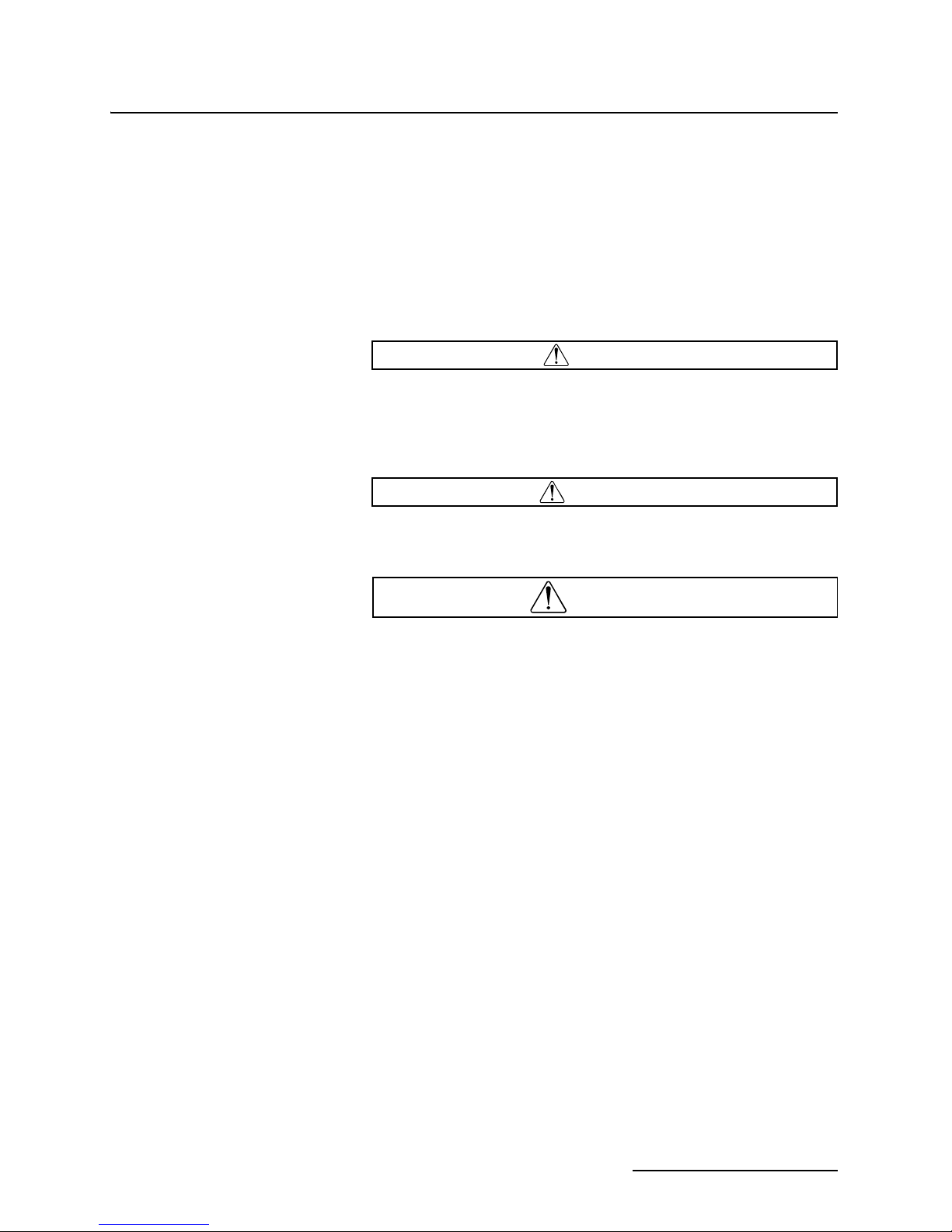
Hazard Symbols The equipment and this manual use symbols used to warn of
hazards. The symbols are explained below.
Hazard Symbols
Warnings and Cautions
The exclamation point within the triangle is a warning sign alerting you of
important instructions in the instrument’s technical reference manual.
The lightning flash and arrowhead within the triangle is a warning sign alerting you of “dangerous voltage” inside the product.
Symboles de sécurité
Ce symbole signale l’existence d’instructions importantes relatives au
produit dans ce manuel.
Ce symbole signale la présence d’un danger d’électocution.
Warnungen und Vorsichtshinweise
Advertencias y Precauciones
Das Ausrufezeichen in Dreieck ist ein Warnzeichen, das Sie darauf
aufmerksam macht, daß wichtige Anleitungen zu diesem Handbuch
gehören.
Der gepfeilte Blitz im Dreieck ist ein Warnzeichen, das Sei vor “gefährlichen
Spannungen” im Inneren des Produkts warnt.
Esta señal le advierte sobre la importancia de las instrucciones del manual
que acompañan a este producto.
Esta señal alerta sobre la presencia de alto voltaje en el interior del
producto.
iv

3010 Flow Transmitter
Table of Contents
Section 1 Introduction
1.1 Manual Organization . . . . . . . . . . . . . . . . . . . . . . . . . . . . . . . . . . . . . . . . . . . . . . . . 1-1
1.2 Description. . . . . . . . . . . . . . . . . . . . . . . . . . . . . . . . . . . . . . . . . . . . . . . . . . . . . . . . . 1-1
1.2.1 Interfacing Equipment . . . . . . . . . . . . . . . . . . . . . . . . . . . . . . . . . . . . . . . . . 1-2
1.3 Ultrasonic Level Sensor . . . . . . . . . . . . . . . . . . . . . . . . . . . . . . . . . . . . . . . . . . . . . . 1-2
1.3.1 SETUP Step . . . . . . . . . . . . . . . . . . . . . . . . . . . . . . . . . . . . . . . . . . . . . . . . . . 1-3
1.3.2 Labels . . . . . . . . . . . . . . . . . . . . . . . . . . . . . . . . . . . . . . . . . . . . . . . . . . . . . . . 1-3
1.4 Controls, Indicators, and Terminal Blocks . . . . . . . . . . . . . . . . . . . . . . . . . . . . . . . 1-4
1.5 Technical Specifications . . . . . . . . . . . . . . . . . . . . . . . . . . . . . . . . . . . . . . . . . . . . . . 1-6
Section 2 Programming
2.1 Operating Theory . . . . . . . . . . . . . . . . . . . . . . . . . . . . . . . . . . . . . . . . . . . . . . . . . . . 2-1
2.1.1 Ultrasonic Level Sensor Theory and Applications . . . . . . . . . . . . . . . . . . . . 2-1
2.1.2 Error Factors Affecting Performance . . . . . . . . . . . . . . . . . . . . . . . . . . . . . . 2-2
2.1.3 Error Factors and Flow Compensation . . . . . . . . . . . . . . . . . . . . . . . . . . . . 2-3
2.2 Controls and Indicators . . . . . . . . . . . . . . . . . . . . . . . . . . . . . . . . . . . . . . . . . . . . . . 2-4
2.2.1 Keypad Layout and Functions . . . . . . . . . . . . . . . . . . . . . . . . . . . . . . . . . . . 2-4
2.2.2 Display . . . . . . . . . . . . . . . . . . . . . . . . . . . . . . . . . . . . . . . . . . . . . . . . . . . . . . 2-5
2.2.3 Power Failures . . . . . . . . . . . . . . . . . . . . . . . . . . . . . . . . . . . . . . . . . . . . . . . . 2-5
2.3 Programming. . . . . . . . . . . . . . . . . . . . . . . . . . . . . . . . . . . . . . . . . . . . . . . . . . . . . . . 2-6
2.3.1 Programming Overview . . . . . . . . . . . . . . . . . . . . . . . . . . . . . . . . . . . . . . . . . 2-6
2.3.2 List of Program Steps . . . . . . . . . . . . . . . . . . . . . . . . . . . . . . . . . . . . . . . . . . 2-7
2.3.3 Programming Sequence in Detail . . . . . . . . . . . . . . . . . . . . . . . . . . . . . . . . . 2-8
2.3.4 Equations Used in Flow Conversion . . . . . . . . . . . . . . . . . . . . . . . . . . . . . . 2-13
2.3.5 Default Program . . . . . . . . . . . . . . . . . . . . . . . . . . . . . . . . . . . . . . . . . . . . . 2-14
2.4 Programming Examples . . . . . . . . . . . . . . . . . . . . . . . . . . . . . . . . . . . . . . . . . . . . . 2-16
2.4.1 Programming for a Parshall Flume . . . . . . . . . . . . . . . . . . . . . . . . . . . . . . 2-16
2.4.2 Programming for a Cipolletti Weir . . . . . . . . . . . . . . . . . . . . . . . . . . . . . . . 2-18
2.4.3 Programming with the Equation (Device #34) . . . . . . . . . . . . . . . . . . . . . . 2-22
2.4.4 Rectangular Weirs with End Contractions . . . . . . . . . . . . . . . . . . . . . . . . 2-26
2.4.5 Programming Example for a Rectangular Weir with End Contractions . 2-27
Section 3 Installation
3.1 General Comments on Installation . . . . . . . . . . . . . . . . . . . . . . . . . . . . . . . . . . . . . 3-1
3.1.1 Location of the Flow Transmitter . . . . . . . . . . . . . . . . . . . . . . . . . . . . . . . . . 3-1
3.1.2 Portable Operation . . . . . . . . . . . . . . . . . . . . . . . . . . . . . . . . . . . . . . . . . . . . 3-2
3.2 General Wiring Information. . . . . . . . . . . . . . . . . . . . . . . . . . . . . . . . . . . . . . . . . . . 3-2
3.2.1 Mounting and Wiring . . . . . . . . . . . . . . . . . . . . . . . . . . . . . . . . . . . . . . . . . . 3-2
3.2.2 Connection to a Power Source . . . . . . . . . . . . . . . . . . . . . . . . . . . . . . . . . . . . 3-3
3.2.3 Voltage Selector Switch . . . . . . . . . . . . . . . . . . . . . . . . . . . . . . . . . . . . . . . . . 3-3
3.2.4 Wiring the Ultrasonic Level Sensor . . . . . . . . . . . . . . . . . . . . . . . . . . . . . . . 3-4
3.3 Connection to an Isco Sampler. . . . . . . . . . . . . . . . . . . . . . . . . . . . . . . . . . . . . . . . . 3-5
3.4 Connection to a Non-Isco Sampler . . . . . . . . . . . . . . . . . . . . . . . . . . . . . . . . . . . . . . 3-6
3.5 Connection to Other Equipment. . . . . . . . . . . . . . . . . . . . . . . . . . . . . . . . . . . . . . . . 3-6
3.6 Safety Considerations . . . . . . . . . . . . . . . . . . . . . . . . . . . . . . . . . . . . . . . . . . . . . . . . 3-7
3.7 Installing the Ultrasonic Level Sensor . . . . . . . . . . . . . . . . . . . . . . . . . . . . . . . . . . 3-7
v

3010 Flow Transmitter
Table of Contents
Section 4 Options and Accessories
Section 5 Maintenance and Troubleshooting
3.7.1 Mounting the Ultrasonic Level Sensor . . . . . . . . . . . . . . . . . . . . . . . . . . . . . 3-8
3.7.2 Minimization of Level Measurement Errors . . . . . . . . . . . . . . . . . . . . . . . . 3-9
4.1 High-Low Alarm Relay Box . . . . . . . . . . . . . . . . . . . . . . . . . . . . . . . . . . . . . . . . . . . 4-1
4.1.1 Setting the Limit Switches . . . . . . . . . . . . . . . . . . . . . . . . . . . . . . . . . . . . . . 4-2
4.1.2 Installation . . . . . . . . . . . . . . . . . . . . . . . . . . . . . . . . . . . . . . . . . . . . . . . . . . . 4-2
4.1.3 Wiring . . . . . . . . . . . . . . . . . . . . . . . . . . . . . . . . . . . . . . . . . . . . . . . . . . . . . . . 4-3
4.2 Connection to External Serial Devices. . . . . . . . . . . . . . . . . . . . . . . . . . . . . . . . . . . 4-4
4.3 Remote Totalizer . . . . . . . . . . . . . . . . . . . . . . . . . . . . . . . . . . . . . . . . . . . . . . . . . . . . 4-5
4.3.1 Wiring . . . . . . . . . . . . . . . . . . . . . . . . . . . . . . . . . . . . . . . . . . . . . . . . . . . . . . . 4-5
4.4 Extension Cables for the Sensor. . . . . . . . . . . . . . . . . . . . . . . . . . . . . . . . . . . . . . . . 4-6
4.4.1 Connecting the Cables . . . . . . . . . . . . . . . . . . . . . . . . . . . . . . . . . . . . . . . . . . 4-6
4.5 Quick-Disconnect Box . . . . . . . . . . . . . . . . . . . . . . . . . . . . . . . . . . . . . . . . . . . . . . . . 4-6
4.6 4-20 mA Analog Output . . . . . . . . . . . . . . . . . . . . . . . . . . . . . . . . . . . . . . . . . . . . . . 4-6
4.6.1 Wiring . . . . . . . . . . . . . . . . . . . . . . . . . . . . . . . . . . . . . . . . . . . . . . . . . . . . . . . 4-6
5.1 Care of the Flow Transmitter Case . . . . . . . . . . . . . . . . . . . . . . . . . . . . . . . . . . . . . 5-1
5.1.1 Care of the Case Seal . . . . . . . . . . . . . . . . . . . . . . . . . . . . . . . . . . . . . . . . . . . 5-1
5.1.2 Preventing Moisture Damage . . . . . . . . . . . . . . . . . . . . . . . . . . . . . . . . . . . . 5-1
5.2 Care of the Sensor and Cables . . . . . . . . . . . . . . . . . . . . . . . . . . . . . . . . . . . . . . . . . 5-2
5.2.1 Cable Inspection . . . . . . . . . . . . . . . . . . . . . . . . . . . . . . . . . . . . . . . . . . . . . . 5-2
5.3 Mechanical and Electrical Components. . . . . . . . . . . . . . . . . . . . . . . . . . . . . . . . . . 5-2
5.3.1 Accessing the Terminal PCB . . . . . . . . . . . . . . . . . . . . . . . . . . . . . . . . . . . . . 5-2
5.3.2 Accessing the Flow Transmitter PCB . . . . . . . . . . . . . . . . . . . . . . . . . . . . . . 5-2
5.4 Fuse Replacement . . . . . . . . . . . . . . . . . . . . . . . . . . . . . . . . . . . . . . . . . . . . . . . . . . . 5-3
5.5 Display Warnings . . . . . . . . . . . . . . . . . . . . . . . . . . . . . . . . . . . . . . . . . . . . . . . . . . . 5-3
5.6 Troubleshooting Hints . . . . . . . . . . . . . . . . . . . . . . . . . . . . . . . . . . . . . . . . . . . . . . . 5-3
5.6.1 If Serious Problems Occur . . . . . . . . . . . . . . . . . . . . . . . . . . . . . . . . . . . . . . . 5-4
5.6.2 Processor Servicing . . . . . . . . . . . . . . . . . . . . . . . . . . . . . . . . . . . . . . . . . . . . 5-4
5.6.3 Preliminary Troubleshooting Steps . . . . . . . . . . . . . . . . . . . . . . . . . . . . . . . 5-4
5.6.4 Precautions for Servicing AC-Powered Equipment . . . . . . . . . . . . . . . . . . . 5-5
5.6.5 Precautions for Servicing CMOS Circuitry . . . . . . . . . . . . . . . . . . . . . . . . . 5-6
5.6.6 Call for Assistance . . . . . . . . . . . . . . . . . . . . . . . . . . . . . . . . . . . . . . . . . . . . . 5-8
5.7 Circuit Boards . . . . . . . . . . . . . . . . . . . . . . . . . . . . . . . . . . . . . . . . . . . . . . . . . . . . . . 5-8
5.7.1 Terminal Board . . . . . . . . . . . . . . . . . . . . . . . . . . . . . . . . . . . . . . . . . . . . . . . 5-8
5.7.2 CPU Board . . . . . . . . . . . . . . . . . . . . . . . . . . . . . . . . . . . . . . . . . . . . . . . . . . . 5-8
5.7.3 Ultrasonic Board Description . . . . . . . . . . . . . . . . . . . . . . . . . . . . . . . . . . . . 5-9
Appendix A Replacement Parts List
A.1 Replacement Parts List . . . . . . . . . . . . . . . . . . . . . . . . . . . . . . . . . . . . . . . . . . . . . . A-1
A.2 Accessories List. . . . . . . . . . . . . . . . . . . . . . . . . . . . . . . . . . . . . . . . . . . . . . . . . . . . . A-6
Appendix B General Safety Procedures
B.1 Practical Safety Precautions . . . . . . . . . . . . . . . . . . . . . . . . . . . . . . . . . . . . . . . . . . B-1
B.1.1 Hazards . . . . . . . . . . . . . . . . . . . . . . . . . . . . . . . . . . . . . . . . . . . . . . . . . . . . . B-1
B.1.2 Planning . . . . . . . . . . . . . . . . . . . . . . . . . . . . . . . . . . . . . . . . . . . . . . . . . . . . . B-2
B.1.3 Adverse Atmospheres . . . . . . . . . . . . . . . . . . . . . . . . . . . . . . . . . . . . . . . . . . B-2
B.1.4 Entering Manholes . . . . . . . . . . . . . . . . . . . . . . . . . . . . . . . . . . . . . . . . . . . . B-2
B.1.5 Traffic Protection . . . . . . . . . . . . . . . . . . . . . . . . . . . . . . . . . . . . . . . . . . . . . . B-3
B.1.6 Falling Objects . . . . . . . . . . . . . . . . . . . . . . . . . . . . . . . . . . . . . . . . . . . . . . . B-3
B.1.7 Removing the Covers . . . . . . . . . . . . . . . . . . . . . . . . . . . . . . . . . . . . . . . . . . B-3
B.1.8 Other Precautions . . . . . . . . . . . . . . . . . . . . . . . . . . . . . . . . . . . . . . . . . . . . . B-3
vi

3010 Flow Transmitter
Table of Contents
B.1.9 Emergencies . . . . . . . . . . . . . . . . . . . . . . . . . . . . . . . . . . . . . . . . . . . . . . . . . B-4
B.1.10 Field Equipment . . . . . . . . . . . . . . . . . . . . . . . . . . . . . . . . . . . . . . . . . . . . . B-4
B.2 Lethal Atmospheres in Sewers . . . . . . . . . . . . . . . . . . . . . . . . . . . . . . . . . . . . . . . . B-4
B.3 Hazardous Gases . . . . . . . . . . . . . . . . . . . . . . . . . . . . . . . . . . . . . . . . . . . . . . . . . . . B-6
List of Figures
1-1 Model 3010 Flow Transmitter . . . . . . . . . . . . . . . . . . . . . . . . . . . . . . . . . . . . . . . . . 1-1
1-2 Ultrasonic Level Sensor . . . . . . . . . . . . . . . . . . . . . . . . . . . . . . . . . . . . . . . . . . . . . . 1-3
1-3 Interior View of Transmitter, Showing Terminal Blocks . . . . . . . . . . . . . . . . . . . 1-5
2-1 Simplified 3010 Programming Flowchart . . . . . . . . . . . . . . . . . . . . . . . . . . . . . . . 2-15
3-1 View of Case Latch, Showing Lock Shackle . . . . . . . . . . . . . . . . . . . . . . . . . . . . . . 3-1
3-2 USLS Floor Mount . . . . . . . . . . . . . . . . . . . . . . . . . . . . . . . . . . . . . . . . . . . . . . . . . . 3-9
3-3 Foam and Oil on the Surface of the Stream . . . . . . . . . . . . . . . . . . . . . . . . . . . . . 3-12
3-4 Small Pipes and Narrow Channels . . . . . . . . . . . . . . . . . . . . . . . . . . . . . . . . . . . . 3-12
3-5 Ultrasonic Level Sensor “Dead Band” . . . . . . . . . . . . . . . . . . . . . . . . . . . . . . . . . . 3-14
3-6 USLS Mounting Methods . . . . . . . . . . . . . . . . . . . . . . . . . . . . . . . . . . . . . . . . . . . 3-15
3-7 USLS Mounting Methods (continued) . . . . . . . . . . . . . . . . . . . . . . . . . . . . . . . . . . 3-16
4-1 High-Low Alarm Relay Box (Cover Removed) . . . . . . . . . . . . . . . . . . . . . . . . . . . . 4-2
4-2 Interconnection of 3010 and Alarm Boxe(s) . . . . . . . . . . . . . . . . . . . . . . . . . . . . . . 4-4
4-3 Remote Totalizer . . . . . . . . . . . . . . . . . . . . . . . . . . . . . . . . . . . . . . . . . . . . . . . . . . . 4-5
5-1 Terminal Printed Circuit Board Component Layout . . . . . . . . . . . . . . . . . . . . . . 5-11
5-2 CPU PCB Component Layout . . . . . . . . . . . . . . . . . . . . . . . . . . . . . . . . . . . . . . . . 5-12
5-3 Ultrasonic PCB Component Layout . . . . . . . . . . . . . . . . . . . . . . . . . . . . . . . . . . . 5-13
List of Tables
1-1 3010 Controls, Indicators, and Wiring Terminals . . . . . . . . . . . . . . . . . . . . . . . . . 1-4
1-2 Technical Specifications for the Model 3010 Flow Transmitter . . . . . . . . . . . . . . 1-6
1-3 Technical Specification for the USLS . . . . . . . . . . . . . . . . . . . . . . . . . . . . . . . . . . . 1-6
2-1 Primary Measuring Devices . . . . . . . . . . . . . . . . . . . . . . . . . . . . . . . . . . . . . . . . . . 2-9
2-2 Equations Used in the Model 3010 . . . . . . . . . . . . . . . . . . . . . . . . . . . . . . . . . . . . 2-13
2-3 Values of N1 for Flow Rate in CFS . . . . . . . . . . . . . . . . . . . . . . . . . . . . . . . . . . . . 2-27
2-4 Values of N2 for Flow Rate in CFS . . . . . . . . . . . . . . . . . . . . . . . . . . . . . . . . . . . . 2-27
4-1 3000 Series Wiring Instructions . . . . . . . . . . . . . . . . . . . . . . . . . . . . . . . . . . . . . . . 4-3
B-1 Hazardous Gases . . . . . . . . . . . . . . . . . . . . . . . . . . . . . . . . . . . . . . . . . . . . . . . . . . . B-6
vii

3010 Flow Transmitter
Table of Contents
viii

3010 Flow Transmitter
Section 1 Introduction
The first section of the 3010 Flow Transmitter instruction
manual provides a general introduction to the instrument. It
includes a brief discussion of the organization of the manual, an
overall description of the flow transmitter and ultrasonic level
sensor (USLS), and technical specifications.
1.1 Manual Organization The purpose of this manual is to provide the information nec-
essary to program, operate, maintain, and service the 3010 Flow
Transmitter. To accomplish this, the manual is organized into
five sections and an appendix. This first section is a general
introduction to the flow transmitter. The second section contains
information on operation, programming, and some examples of
programming for specific objectives. The third section provides
installation instructions. The fourth section describes available
options and their uses. The fifth section contains maintenance
information and servicing tips to assist you in correcting
problems that may occur. Appendix A contains lists of
replacement parts and accessories.
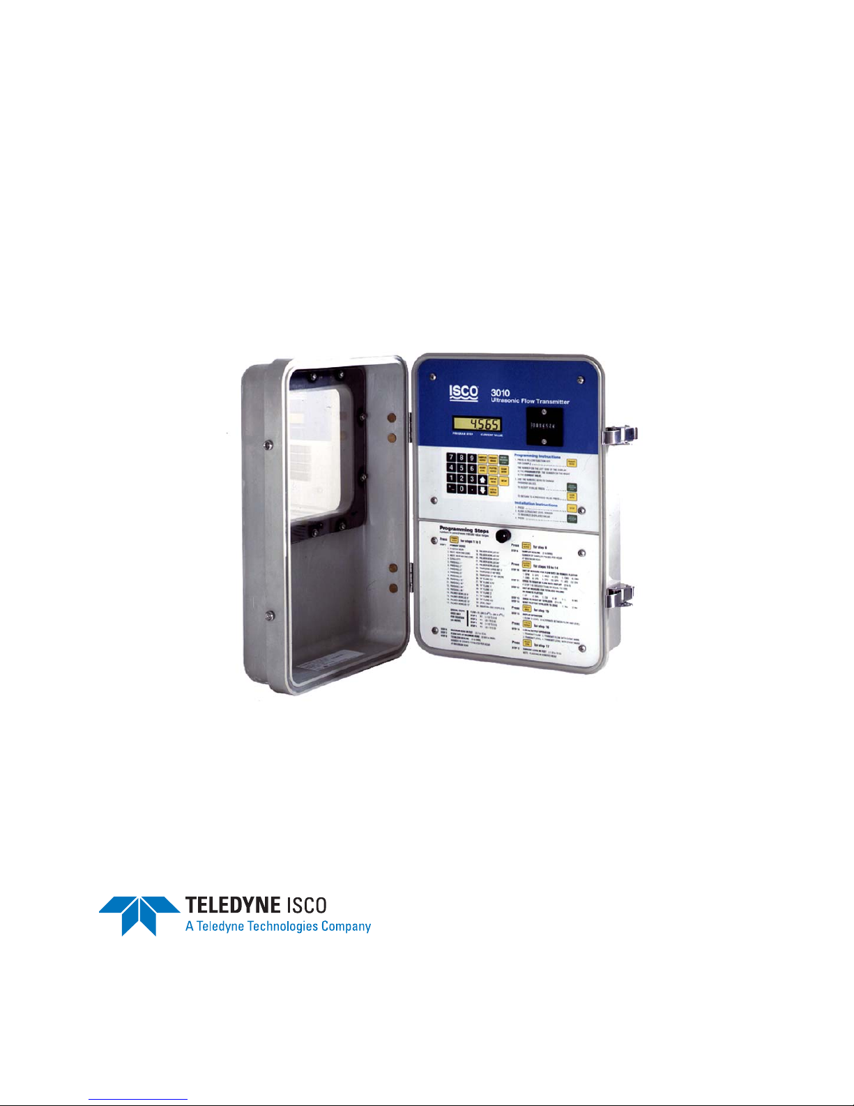
1.2 Description The 3010, shown in Figure 1-1, uses ultrasonic level mea-
surement. You normally use the flow transmitter with some type
of primary measuring device to measure flow rate in an open
channel. The 3010 uses level-to-flow rate conversions derived
from a stored equation, covering the majority of open channel
flow measurement situations. If needed, you can enter the coefficients and powers of the flow equation. However, you can use
most standard weirs and flumes without the need for the
equation. A 6-digit LCD (Liquid Crystal Display) prompts you
through setup, displays the choices for the current programming
step, and displays level and/or flow rate.
Figure 1-1 Model 3010 Flow Transmitter
1-1

3010 Flow Transmitter
Note
Section 1 Introduction
1.2.1 Interfacing Equipment The 3010 is compatible with the following Teledyne Isco
equipment:
• 3700 series samplers, 6700 series samplers, and GLS
and Glacier compact samplers
Options and Accessories:
• Resettable 7-digit mechanical flow totalizer. (A nonresettable flow totalizer is a standard feature of the 3010.)
• High-Low Alarm Relay Box
• Quick-Disconnect Box
• Extension Cables for the Ultrasonic Level Sensor
• Ultrasonic Level Sensor Cable Clamp and Spreader Bar
• Ultrasonic Mount, Calibration Target, Cable
Straightener, and Sunshade
• Remote Totalizer
• Flow Transmitter-to-Sampler Connect Cable
1.3 Ultrasonic Level
Sensor
Throughout this manual, we describe various accessories
available for the 3010. We have listed the part numbers for all
these items on an Accessory List, that you will find at the back
of Appendix A Replacement Parts List. You can obtain part
numbers for other Teledyne Isco equipment by calling the factory.
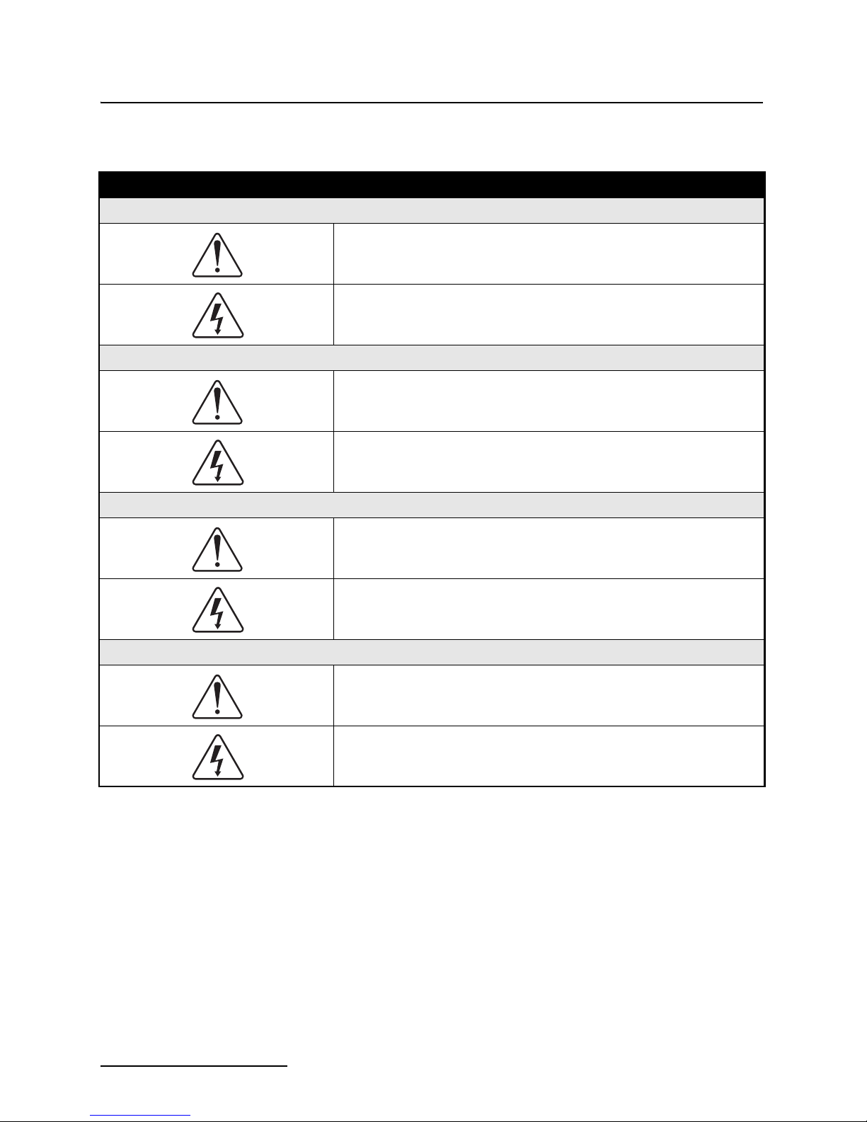
The Ultrasonic Level Sensor, or USLS, shown in Figure 1-2, measures liquid level without contacting the flow stream. The USLS
consists of an ultrasonic transducer and associated electronics
mounted in a housing, and a shielded cable that connects the
level sensor to the flow transmitter. This cable lets you suspend
the level sensor by the cable alone over a flow stream in temporary installations. For more permanent installations, a
mounting bracket is available to attach the ultrasonic level
sensor securely to the mounting surface. The level sensor is provided with a 50-foot cable (15.2 meters). For distances greater
than 50 feet, you must use the Quick-Disconnect Box (a type of
splice box) with extension cables. The maximum distance
between the flow transmitter and the level sensor is 1,000 feet
(304.8 meters).
The USLS mounts over the flow stream, and periodically
transmits an ultrasonic pulse to the surface of the stream. The
water surface reflects the echo of the pulse back from the stream
to the level sensor. The elapsed time between pulse and return
echo is proportional to the distance from the level sensor to the
liquid surface. The 3010 uses this time/distance relationship and
a referenced “zero” point in the flow stream to calculate liquid
level. Then, by applying values specific for the primary device in
use, the 3010 calculates flow rate from the measured level. The
USLS has a temperature probe built into its housing to measure
1-2
3010 Flow Transmitter
E## ##
Section 1 Introduction
ambient air temperature. The 3010 uses this temperature measurement to compensate for inaccuracies in ultrasonic measurement caused by changes in the air temperature between the
transducer and the flow stream.
Figure 1-2 Ultrasonic Level Sensor
1.3.1 SETUP Step The 3010 has a special feature to help you correctly align the
ultrasonic level sensor. This Setup step lets you orient the ultrasonic level sensor over the flow stream while an assistant
watches the flow transmitter's display.
The number on the left represents the strength of the sensor’s
return signal, or gain. The number on the right indicates how
much noise is in the return signal due to surface roughness, etc.
(the higher the number, the less noise is present). As long as the
number on the left side of the display is increasing, the sensor is
approaching optimal alignment. When the Setup number
reaches the highest reading, the level sensor is in proper
alignment. If you continue to adjust the level sensor and the
number displayed begins to fall, you have gone past the optimal
alignment.
1.3.2 Labels The 3010 comes with a set of adhesive labels to permit the
display and the mechanical totalizer to express greater values
than the number of digits available on the display. Where
extremely large flow volumes are involved, you can add trailing
zeroes to the display to make more meaningful numbers. To
1-3

3010 Flow Transmitter
Section 1 Introduction
provide a handy reference for your programming selections,
there are adhesive labels for units of measure you can attach to
the flow transmitter.
1.4 Controls, Indicators,
and Terminal Blocks
Table 1-1 lists the controls, indicators, and terminal blocks for
wiring to the 3010 Flow Meter, and briefly describes their functions. Refer to Figure 1-3 for a view of the terminal blocks.
Table 1-1 3010 Controls, Indicators, and Wiring Terminals
CONTROLS SETTINGS FUNCTION
Keypad None Specific 23 key, 6-column matrix. Program flow transmitter by key-
strokes prompted by messages on the display.
INDICATORS READING FUNCTION
Display Multifunction 6-digit, 7-segment liquid crystal display (LCD). Prompts
TERMINALS TYPE FUNCTION
Power 3 #8 screws on block TS1. Large Ter -
minals 1, 2, and 3.
4-20 mA Output 2 #6 screws on block TS2. Terminals
4 and 5.
Remote Totalizer 2 #6 screws on block TS2. Terminals
6 and 7.
2312 Interface 3 #6 screws on block TS2. Terminals
8, 9, and 10.
you through program set up; displays current menu selections, displays level or flow rate.
Connects 120/240 VAC power to flow transmitter. #1 = Hot.
#2 = Ground. #3 = Neutral.
Provides standard 4-20 mA current loop output (variable
with level or flow rate) to be used to control compatible
equipment such as a chart recorder or a chlorinator.
Connects flow transmitter to external mechanical remote
totalizer.
Originally for connecting the 3010 to the Model 2312 strip
chart plotter (obsolete). Currently used for connecting to
other external serial devices or an alarm relay box.
Bottle Number
(BLT NUM)
Event Mark 2 #6 screws on TS2.
Sampler Output 2 #6 screws on TS3.
Ultrasonic Level
Sensor
and Temperature
Sensor
2 #6 screws on block TS2. Terminals
11 and 12.
Terminal 13 = + 12VDC
Terminal 14 = - Event Mark
Terminal 15 = Sampler
Terminal 16 = Dry Contact
4 #6 screws on block TS3. Terminals
20, 21, 22, and 23.
Provides bottle number input signal to flow transmitter from
an Isco automatic wastewater sampler.
Provides event mark input signal to flow transmitter from an
Isco Sampler.
Provides flow pulse from flow transmitter to flow pace an
Isco sampler.
Provides connection for ultrasonic level sensor and temperature sensor.
1-4

3010 Flow Transmitter
Section 1 Introduction
Figure 1-3 Interior View of Transmitter, Showing Terminal Blocks
1-5

3010 Flow Transmitter
Section 1 Introduction
1.5 Technical
Specifications
The technical specifications for the 3010 and ultrasonic level
sensor (USLS) are listed below in Tables 1-2 and 1-3.
Table 1-2 Technical Specifications for the Model 3010 Flow Transmitter
Size (H x W x D) 15
Weight 10 lbs (4.5 kg)
Material High-impact molded polystyrene structural foam.
Power 104-127 VAC, 0.075 amp, 50 to 60 Hz
Overcurrent Protection
Display 6-character, 7-segment, alphanumeric liquid crystal
Display Modes Level, flow rate, alternating
Built-in Level-to-Flow Rate Conversions Weirs: V-notch, Rectangular with/without end contractions, Cipolletti.
Level-to-Flow Rate Conversion Accuracy
Sampler Output Isolated contact closure, rated 1 amp @ 48 VDC
Sampler Input Event marks (sample events), bottle numbers
1
/4 inches x 105/8 inches x 73/8 inches
(38.7 cm x 27 cm x 18.7 cm)
Self-certified NEMA 4X enclosure.
or
210-260 VAC, 0.038 amp, 50 to 60 Hz (see Section 3)
1
/2 amp slow-blow fuse
Flumes: Parshall, Palmer-Bowlus, Trapezoidal, “H”.
Equation: Two-term power equation.
1% Full Scale
Analog Output Isolated 4-20 mA into 0 to 1,000 ohm; level or flow rate, with or without sam-
Serial Data Port Compatible with 2312 Plotter (no longer sold), High-Low Alarm Relay Box,
Compatible Isco Recording Devices Model 2410 Circular Chart Recorder (no longer sold), Model 2312 Plotter
Totalizer 7-Digit mechanical counter, non-resettable
External Totalizer Output 12 VDC pulse
Operating Temperature -20° F to 140° F (-30° C to 60° C)
Storage Temperature -50° F to 150° F (-46° C to 66° C)
Relative Humidity 0 - 100%
pler event marks. Accuracy: 1 % of full scale.
and other external serial devices.
(no longer sold)
Table 1-3 Technical Specification for the USLS
Length 6.9 inches (17.5 cm)
Diameter 3.6 inches (9.1 cm)
Weight 2 lbs, 10 oz (1.2 kg)
Range Minimum distance from sensor face to liquid: 24 inches (0.61 meters)
Maximum distance form sensor face to liquid: 12 feet (3.6 meters)
Span 0 to 10 feet (0 to 3 meters)
Operating Temperature -22 ° F to 140°F (-30° C to 60° C)
Storage Temperature -40° F to 158° F (-40° C to 70° C)
1-6

3010 Flow Transmitter
Section 2 Programming
The following section explains how to program the flow transmitter. There are also sections on the operating theory, control
and indicator descriptions, setup procedures, and programming
examples.
2.1 Operating Theory When measuring flow rate, the 3010 normally uses a primary
measuring device (weir or flume) or other open channel flow
arrangement, where a known relationship exists between level
and flow rate. The level measuring device is an Ultrasonic Level
Sensor that measures the liquid level in the flow stream. The
flow transmitter electronically converts the level reading into a
properly scaled flow rate value. The flow transmitter also provides standard flow-related output signals to be used for:
• Flow-paced wastewater sampling.
• Recording flow rate information on an external
printer/plotter, circular chart recorder, or other external
serial device
• Connection to a 4 - 20 mA compatible device
• Tripping remote high and low alarm relays
The flow transmitter contains microprocessor-controlled circuitry to calculate level and flow rates from the signals produced
by the level sensor. It stores programming instructions and
operates the display. A backlit alphanumeric liquid crystal
display (LCD) shows level and flow rate information. The display
also prompts programming of the flow transmitter during initial
setup or subsequent changes. Auxiliary equipment used with the
3010 connects to the terminal blocks on the printed circuit board
in the bottom section of the flow transmitter case.
2.1.1 Ultrasonic Level
Sensor Theory and
Applications
The Ultrasonic Level Sensor (USLS) is mounted over the flow
stream. It measures liquid level by emitting an ultrasonic pulse
and then measuring the time it takes for the echo to return from
the surface of the liquid. The USLS consists of an enclosure with
a single transducer acting both as the pulse transmitter and the
echo receiver. Since the speed of the pulse through the air varies
with temperature, the level sensor has temperature compensation built in. The microprocessor program automatically compensates for speed-of-sound changes caused by air temperature
changes.
Transducer Operation – The USLS emits a strong ultrasonic
pulse several times a second. After transmitting the pulse, the
flow transmitter electronically switches the level sensor transducer into a receiver or microphone, ready to receive or hear the
2-1

3010 Flow Transmitter
Section 2 Programming
echo reflected back from the flow stream. The transducer converts the echo sound into a small pulse that the circuitry in the
flow transmitter amplifies and detects to produce an “echo
received” signal. The time between the transmitted pulse and
received echo is proportional to the distance between the transducer and the surface of the stream. The flow transmitter uses
this distance to determine the liquid level in the stream.
Validity Tests and Error Display – The flow transmitter subjects the measured level to several validity tests. If the unit
cannot obtain a valid level, it repeats the process. Meanwhile, the
last good level reading will continue to appear on the display. If,
after approximately four minutes, the flow transmitter cannot
obtain a valid reading, the 3010 will show EE 80 on the display.
In such instances, it may be necessary to realign the level sensor
or check the operation of the flow transmitter.
Ambient Air Temperature Factor – The 3010 uses an ultrasonic distance measurement technique based on the speed of
sound in air. Since the speed of sound in air varies with temperature (approximately 1% for 10× of variation), you must provide
compensation. The level sensor uses the air temperature sensor
and microprocessor-based compensation to accurately account
for air temperature variations. See also Section 2.1.2.
Return Echo Amplifier Compensation – The signal strength
of the returned echo depends on several factors including the distance from the transducer to the water surface. For every
1
2
/2-foot increase in the distance between the transducer and the
liquid surface, the strength of the returned echo decreases by
half, so designers must compensate the gain of the return echo
amplifier for distance. As the distance increases between the
transducer and the liquid surface, the gain of the echo amplifier
increases with time to compensate for the decreasing signal
strength of the echo. This type of amplifier, whose gain characteristic is based on a repeating time interval, is referred to as a
“ramp gain” amplifier.
2.1.2 Error Factors Affecting
Performance
2-2
Several external factors can influence both the initial pulse and
reflected sound wave, causing the ultrasonic measurement
system to produce errors. These factors fall broadly into two
classes.
Velocity Errors – These errors result when the flow transmitter is unable to accurately calculate the velocity of sound.
They are “proportional” errors, in that the degree of error
increases as the distance between the level sensor and the
surface of the flow stream increases.
Echo Detection Errors – These errors arise from problems the
flow transmitter can have measuring the time between transmitting the ultrasonic pulse and receiving the echo. Anything
that absorbs sound can cause these errors. This makes the echo
amplifier detect the returned signal either earlier or later than
intended in the design of the “ramp gain” amplifier. Errors of this

3010 Flow Transmitter
Velocity 1050 1 Temperature459.67+=
Section 2 Programming
sort will generally be of an “absolute” nature; the distance
between the transducer and the water will not affect them to any
great extent.
2.1.3 Error Factors and Flow
Compensation
Following are specific factors affecting the accuracy of the 3010
with the measures used for compensation of the more significant
factors.
Barometric Pressure – The velocity of sound is essentially
independent of barometric pressure. Changes in barometric
pressure provide no significant cause of error.
Beam Angle – The flow transmitter must only respond to surfaces within a specific area. The transducer can only “see” items
inside a “cone” whose apex is the ultrasonic transducer. The
beam angle is the angle across this cone. If the beam angle is too
wide, the flow transmitter will detect unwanted surfaces, such as
the walls of the channel. If the beam angle is too narrow, setup of
the installation is difficult and the flow transmitter may never
detect an echo.
Humidity – The velocity of sound varies only slightly with
humidity (maximum 0.35% at 68°F). Because the effect is small,
the 3010 does not provide compensation for humidity. Humidity,
however, does have an effect on the reduction of the echo. Under
extreme humidity conditions, the reduction of the sound wave
may be inconsistent with the characteristics of the “ramp gain”
amplifier, causing an echo detection error.
Noise – Background noise can interfere with the operation of the
flow transmitter. The unit must filter out this noise, or it may
trigger on the noise rather than the returned echo. The 3010 uses
a tuned circuit to filter out unwanted noise outside the operating
frequency. Noise in the operating frequency range (49 kHz) can
render the system unstable. The unit uses software algorithms to
eliminate most sporadic noise pulses occurring within the flow
transmitter's operating frequency range.
Surface Objects – Objects or foam floating on the surface of the
flow stream can absorb or weaken the ultrasonic pulse. If the
foam or material reduce the pulses enough, the unit will lose the
echo altogether. In less severe cases, there may be an echo
detection error.
Temperature – The velocity of sound at a given temperature
may be approximated by the following equation:
Where velocity is in feet per second and temperature is in
degrees F. Temperature changes have a significant effect on the
velocity of sound (approximately 7% between 32°F and 104°F).
This variable is significant enough to require compensation. Consequently, the 3010 provides temperature compensation. There is
a temperature sensor embedded in the level sensor. However, the
temperature of the level sensor and air may not be exactly the
same, and the temperature sensor cannot measure temperature
2-3

3010 Flow Transmitter
Note
Section 2 Programming
perfectly. As a result, the equations used to calculate the velocity
of sound in air are approximations, including the equation shown
above.
Waves – Waves or extreme turbulence on the surface of the flow
stream can deflect the sound energy so it does not return to the
transducer. Waves may also make the sound return to the transducer by an indirect path. In the first case, the flow transmitter
will not receive an echo. In the second case, the additional time
lapse will cause an echo error that will appear as an incorrect
level reading. The 3010 has a software algorithm to reject occasional readings that deviate substantially from normal. However,
if the waves are severe, the flow transmitter will not function and
will indicate a “no echo” condition.
Wavelength – You can determine the wavelength of sound by
dividing the velocity of the sound by the frequency. The frequency
of the 3010 is about 49 kHz. You can find the length of a 49 kHz
sound wave by dividing 1,125 feet /second by 49,000, which is
0.02296 feet or 0.276 inches.
Wave (Echo) Detect Error – Under ideal conditions the transducer can detect the same wave front of the returning echo.
However, any noise or abnormal attenuation may cause some
transducers to detect an earlier or a later wave. When the attenuation of the returned echo does not match the gain slope of the
amplifier, the circuit will eventually detect a different cycle of the
returned echo as the distance changes. The impact of this
wave-detect error is determined by the wavelength.
Wind – Wind can blow the sound away or significantly reduce
the intensity of the returned echo. Narrow beam angles, advantageous for measuring small flow streams, are a disadvantage in
this situation. Likewise, greater distances to the surface of the
flow stream are more affected by wind.
2.2 Controls and
Indicators
2.2.1 Keypad Layout and
Functions
2-4
You can reduce the effects of these factors substantially by following the suggestions for ultrasonic level sensor installation
found in Section 3.7.
(Arrow Down) – Use this key in the Level Adjust step of the
program; you can use it in place of the number keys to decrease
the level shown on the display.
(Arrow Up) – Use this key with the display in the Level
Adjust step of the program; you can use it instead of the number
keys to increase the level shown on the display.
CLEAR ENTRY – This key lets you return to a previous entry of
a program step. Pressing the key twice in succession will exit you
from the program.

3010 Flow Transmitter
Section 2 Programming
. (DECIMAL) – Use this key with the number keys when
entering numeric values into the program.
ENTER/PROGRAM STEP – Pressing this key will allow you to
enter changes made to the program into memory. To access the
program, first press one of the yellow Function Keys (See below.)
Pressing one of the Function Keys stops the program and allows
you to make changes. After the you make the change and it
appears on the display, pressing ENTER/PROGRAM STEP will
enter the change into memory. It is also possible to step through
the program retained in memory by pressing this key. The
number of the program step will appear on the left side of the
display and the number of the current selection (or value
entered) will appear next to it.
NUMBER KEYS – Use the number keys to enter numeric
values into the program. You can also use them to make a
selection from the options displayed on the label.
+
- (PLUS/MINUS) – Use this key to enter positive or negative
numbers when programming an equation.
FUNCTION KEYS – The yellow keys let you enter the program
of the 3010 at specific steps so you can change selections or
numerical values. These keys govern specific programming steps,
and will be described elsewhere. Refer to Section 2.3.3 for the
detailed descriptions of the Function Keys.
2.2.2 Display The flow transmitter display shows programming choices. After
you complete programming and installation, the display shows
the present flow rate and/or level. There are three operating
modes for the display: level, flow rate, or an alternation between
the two. You can see the display through the window when the
door is closed. The display is a 6- digit, 7-segment liquid crystal.
The letter H on the left side of the display indicates level (or
Head). For better visibility in low light conditions, the LCD is
lighted.
2.2.3 Power Failures If there is a power failure, the LCD will blank and the flow trans-
mitter will stop operating. Momentary power failures (less than
three seconds) should not affect the operation of the unit, as
power stored in the filters will provide some carryover for a brief
period of time. However, if power is off long enough for the
display to blank, flow pulses to the sampler will stop, as will the
mechanical totalizer and the totalizer signal sent to the external
plotter, which will be reset. The unit will not be able to recognize
changes in level during the time power is off. However, memory
will retain the program selections made during setup and when
power is restored, you won't need to reprogram the flow transmitter.
2-5

3010 Flow Transmitter
Section 2 Programming
2.3 Programming Enter program quantities and control certain functions through
the keypad. The number of the selected entry appears on the
display. The display also indicates operational status, and guides
you through the programming sequence by showing the step programmed. Each time you press a key, the unit will beep.
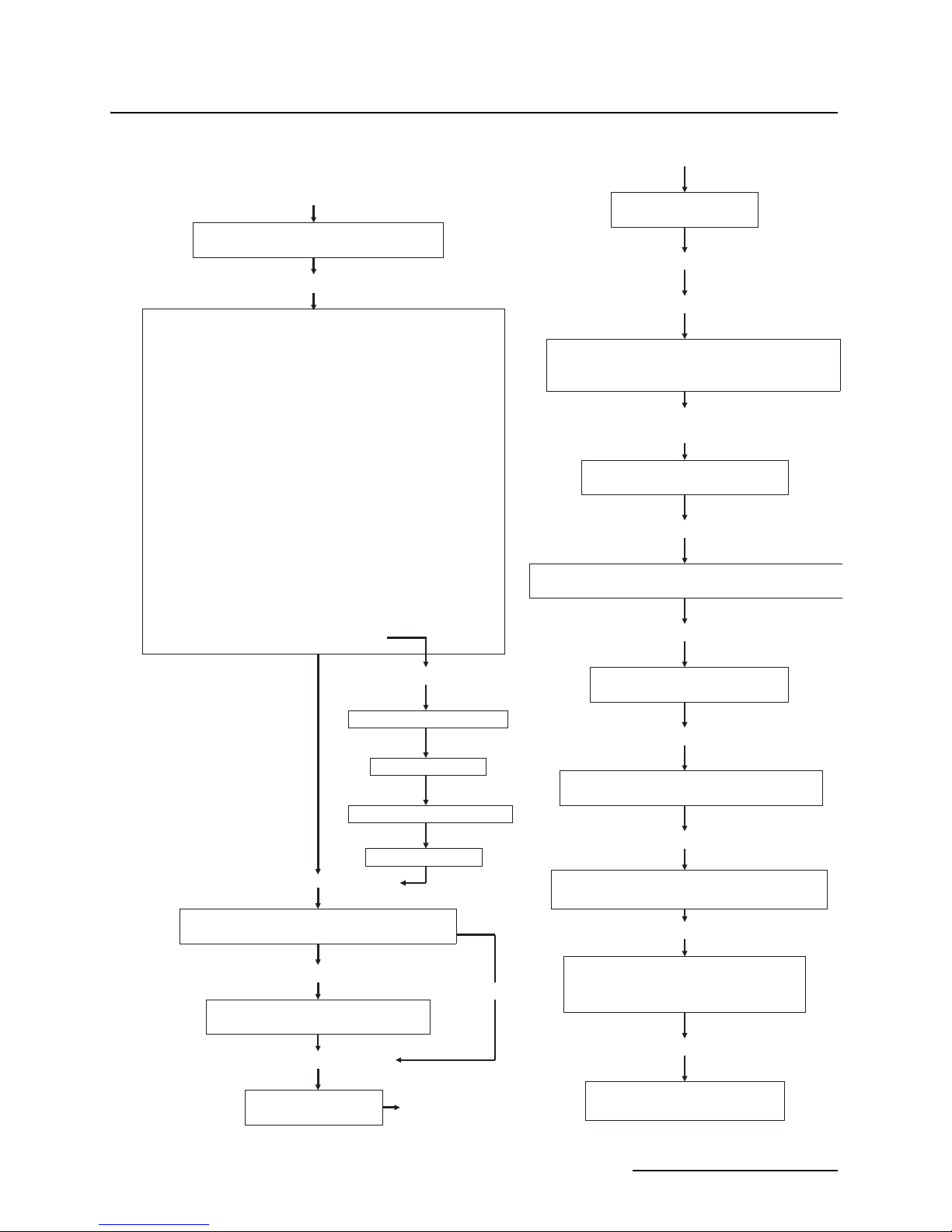
Refer to Figure 2-1 for a flowchart showing programming. At the
back of this manual is a worksheet on which you may write
program selections.
2.3.1 Programming
Overview
Remember that the flow transmitter always has a program in it,
stored in memory, even if it is only the default program installed
at the factory. To program the 3010, press the yellow FUNCTION
KEYS. The display will show the step number on the left and the
number of the choice currently selected (or the numerical value
entered for steps requiring a value) on the right. You will not
need to program all steps. For example, if there is no remote
plotter, you would skip Steps 11 to 15, all involved with operation
of the plotter.
The program steps are printed on the flow transmitter label, and
normally programming proceeds in a logical manner, starting
with Step 1, which sets level in feet or meters. Step 2 selects the
primary measuring device. Then you select maximum head, flow
rate at maximum head, and totalizer scaling. If you aren't using
any other equipment with the 3010, you need to program only
Step 16 PROGRAM OPERATION, and 18 LEVEL ADJUST. If
you are installing the unit for the first time, use the SETUP key
to optimize transducer alignment. Then you use the LEVEL
ADJUST key to calibrate the level sensor.
You only make selections in Steps 10 through 15 and Step 17
when the flow transmitter is connected with associated
equipment. Step 10 governs the relationship between the flow
transmitter and a sampler. Steps 11 - 15 control the output to an
Isco High-Low Alarm Relay Box (a device to trigger other
equipment when flow exceeds or falls below a pre-set value), or
an external serial device.
Step 17 determines the operation of the 4-20 mA current loop
output. Examples of devices that operate from the 4-20 mA
current loop are the Isco Model 2410 Circular Chart Recorder
(discontinued) and process equipment, such as a chlorinator.
After you have installed and programmed the flow transmitter
the first time, it is not necessary to completely reprogram the
unit to enter any changes. Instead, simply select the yellow
function key where you want to make a change and press
ENTER until the desired step is reached; then enter the change.
Automatic Program Advance – After you press ENTER, the
display will automatically advance to the next step and show the
current choice or value entered for that step; the process continues until you have made selections for all steps necessary to
complete the step sequence you have selected, or you press the
CLEAR ENTRY key twice to exit the program.
2-6

3010 Flow Transmitter
Note
Note
Note
Section 2 Programming
Note that you can do all programming for the 3010 in the shop,
except for Setup (concerned with sensor alignment) and the
Adjust Level step, which you must do at the job site after completing the installation.
2.3.2 List of Program Steps Following is a list of the program steps used in the 3010 along
with the choices available or applicable range of values. After the
list there is a detailed explanation of the purpose for each step
and the choices offered.
1. Units of Measure for Level (Feet or Meters).
2. Primary Device (See list of devices in Table 2-1 or refer to
flow transmitter front panel label.)
Steps 3 to 6 are programmed only if #34, Equation, is chosen
in Step 2.
3. N1 (–4,999 to 4,999)
4. P1 (0.1 to 3.0)
5. N2 (–4,999 to 4,999)
6. P2 (0.1 to 3.0)
7. Maximum Head in — (0.1 to 12.0 Feet) (0.03 to 3.66
Meters)
8. Flow Rate at Maximum Head (0.001 to 9999)
9. Totalizer Scaling (Number of counts totalized per hour of
flow at maximum head; 0-9,999.)
Program step 10 only if the flow transmitter is connected to a
sampler.
10. Sampler Scaling (Number of sampler pulses per hour at
maximum head; 0-9,999.)
Program steps 11 to 15 only if there is a remote plotter or other
serial device installed.
11. Unit of Measure for Flow Rate on Remote Plotter
1. GPM 2. GPS 3. MGD 4. CFS 5. CMS 6. CMH
7. CMD 8. LPS 9. CFD 10. GPH 11. AFD 12. CFH
12. Zeros to Right of Flow Rate Display (0 to 6) if value of Step
7 is 1000
13. Unit of Measure for Totalized Volume on Remote Plotter
1. CF 2. GAL 3. CM 4. AF 5. L 6. MG
14. Zeros to Right of Totalizer (0 to 9)
15. Reset Plotter Totalizer to Zero (1. Yes 2. No)
2-7

3010 Flow Transmitter
Note
Section 2 Programming
16. Display Operation
(1. Flow rate 2. Level 3. Alternate between the two)
Program step 17 only if the 3010 controls other external process equipment which operates from the standard 4–20 mA
current loop.
17. 4–20 mA Output Operation (level, flow rate, with or without event mark.)
1. Transmit Flow Rate 2. Transmit Flow Rate with Event
Mark
3. Transmit Level 4. Transmit Level with Event Mark
18. Adjust Level – Current Level in: (Feet –1.0 to 12.5) (Meters
–0.31 to 3.81)
2.3.3 Programming
Sequence in Detail
Following is an explanation for each of the program steps from
the list above.
Step 1 – The first step determines whether the flow transmitter
displays level in feet or meters.
Step 2 – In this step of the programming sequence, identify the
primary measuring device used; then choose the number
referring to that device from the list printed on the label or in
Table 2-1. The 3010 supports 32 common primary measuring
devices. If you wish to use the flow transmitter to measure level
only, select #33. If you want to use the general flow equation,
select #34, and continue to Step 3.
2-8

3010 Flow Transmitter
Section 2 Programming
Table 2-1 Primary Measuring Devices
1. V-NOTCH WEIR 18. PALMER-BOWLUS 15”
2. RECT. WEIR END CONT. 19. PALMER-BOWLUS 18”
3. RECT. WEIR NO END CONT. 20. PALMER-BOWLUS 24”
4. CIPOLETTI 21. PALMER-BOWLUS 30”
5. PARSHALL 1” 22. PALMER-BOWLUS 48”
6. PARSHALL 2” 23. TRAPEZOID LARGE 60 ° V
7. PARSHALL 3” 24. TRAPEZOID 2” 45° WSC
8. PARSHALL 6” 25. TRAPEZOID 12” 45° SRCRC
9. PARSHALL 9” 26. “H” FLUME 0.5’
10. PARSHALL 12” 27. “H” FLUME 0.75’
11. PARSHALL 18” 28. “H” FLUME 1’
12. PARSHALL 24” 29. “H” FLUME 1.5’
13. PARSHALL 36” 30. “H” FLUME 2’
14. PALMER-BOWLUS 6” 31. “H” FLUME 3’
15. PALMER-BOWLUS 8” 32. “H” FLUME 4.5’
16. PALMER-BOWLUS 10” 33. LEVEL ONLY
17. PALMER-BOWLUS 12” 34. EQUATION (SEE STEPS 3-6)
Steps 3 to 6 – These steps will only appear on the display and be
used when you select #34, Equation. These steps allow you to
program the values N1, P1, N2, and P2 for the general flow
equation:
Q (flow rate) = K x (N1 x H
P1
+ N2 x HP2)
See Section 2.4.3 for a detailed discussion about the equation.
With any choice but #34 in Step 2, the program advances automatically to Step 7.
Step 7 - Maximum Head – The 3010 will request entry of a
value for MAXIMUM HEAD. The display will show the value
already in memory. You can enter possible values from 0.1 to 10
feet (0.31 to 3.04 meters). Note that you should always select a
value for maximum head that is reasonable for your particular
application, rather than the maximum value allowable, as the
accuracy of the level-to-flow rate conversion is based on this
value.
Step 8 – Step 8 requests entry of flow rate at maximum head.
Values range from of 0.001 to 9999. Remember to base the flow
rate at maximum head on the value for maximum head you
entered in Step 7, rather than the maximum head allowable for
the device. This information is available from the manufacturer
of the primary measuring device used. The information is also
available from tables published for specific devices in the
Teledyne Isco Open Channel Flow Measurement
Handbook.
2-9

3010 Flow Transmitter
Section 2 Programming
If the value you enter is greater than 9,999, round it off and
reduce it to a number the display can show. For example, 32,537
GPM is greater than the four digits available on the display. So,
first you round the number to 32,540 and then enter the four
most significant digits into the flow transmitter: 3, 2, 5, 4. To
show the overflow from the display, attach a “0” label to the right
of the display to indicate the value displayed is in tens of gallons
rather than gallons. Finally, attach a units of measurement label
for the appropriate units, in this case, “GPM.”
Note also that if the installation includes a plotter, enter the
same flow rate units in Step 11 and the same number of zeroes in
Step 12. For the example just given of 32,537 GPM, you would
enter 1 (GPM) in Step 11 and 1 in Step 12.
Step 9 – In Step 9, the flow transmitter will ask for scaling for
the flow totalizer. This is the number of counts on the totalizer
per hour of flow at maximum head. The value entered ranges
from 0 to 9,999. Note that the selection of the number of counts
per hour is based on flow at maximum head, so the actual
number of counts per hour may be much lower. Note also that if
your installation includes an Isco Model 2312 Plotter (no longer
sold), the units of measure selected for this step will also be
entered for the 2312 in Step 13 and the number of zeroes in Step
14. For example, if you want to totalize in cubic feet and the flow
rate at maximum head is 72.5 CFS:
72.5 CFS x 60 sec/min x 60 min/hr
= 261,000 cubic feet per hour (CFH)
For this example, each count on the totalizer is equal to 1,000
cubic feet.
261,000 CFH 1,000 CF per count = 261 counts per hour
You would then enter 2, 6, 1 for this step. In this instance, you
would place three “0” labels and the CF label to the right of the
display. If the 3010 is connected to a Model 2312, you would then
enter 1 (CF) in Step 13 and 3 in Step 14.
Step 10 – In Step 10, the flow transmitter requests selection of
sampler scaling (flow pulses to the sampler). You don't need to
program this step unless the 3010 is being used with a sampler.
The purpose of this program step is to provide signals to the
sampler to run its own program. The range is from 0 to 9, 999
pulses per hour. Determine this number the same way as in Step
9, previously. Note that selection of the number of flow pulses to
the sampler per hour is based on flow rate at maximum head, so
the actual number of pulses per hour will probably be considerably lower. Determine the number chosen by the volume of flow
that must pass through the primary device before a sample is
taken, rather than a particular interval of time.
For example, assume the flow rate at maximum head for a particular installation is 32,540 GPM.
32,540 GPM x 60 min/hr
= 1,952,400 gallons per hour (GPH)
2-10

3010 Flow Transmitter
Section 2 Programming
We want to send a flow pulse to the associated sampler every
10,000 gallons.
1,952,400 GPH 10,000 gallons per pulse
= 195 pulses per hour
You would then enter 1, 9, 5. If you programmed the associated
sampler to take a sample every 50 pulses, it will take a sample
every 500,000 gallons.
10,000 gallons per pulse x 50 pulses per sample
= 500,000 gallons per sample
If you programmed the sampler to take a sample every 200
pulses, it will take a sample every 2,000,000 gallons.
10,000 gallons per pulse x 200 pulses per sample
= 2 million gallons per sample
Steps 11 to 15 - Plotter Output – You only need to program
these steps if your installation includes an Isco Model 2312
Plotter or other serial device. The selections made here do not
affect operation of the 3010. However, you should choose values
consistent with the choices you made for earlier steps.
Step 11 - Units of Measure for Flow Rate on Remote
Plotter – There are several selections for units of measure
available here. The selection you make will be the units printed
out on the chart. of the 2312. You should select the same units
you selected for Step 8.
Step 12 - Zeros to the Right of the Flow Rate Display (0 to
9) – Program this step with the number of zeros overflowing the
display from the value entered in Step 8. Note that the remote
plotter displays flow rate with scientific notation. For example, a
plotter display of 5.57E+3 would equal 5.57 x 10
3
, which is the
same as 5.57 x 1,000 and that would be 5,570. Consequently, in
this case there is no need to add labels to the plotter display.
Step 13 - Units of Measure for Totalized Volume on
Remote Plotter – Again, selection is dependent on the units of
measure you selected for a previous step, in this case, Step 9.
Step 14 - Zeros to Right of Totalizer (0 to 9) – This step
allows you to add the correct number of trailing zeros to the
plotter’s totalizer to make meaningful numbers from large flow
rates. The number you select is the same as the number of zeros
overflowing the display in Step 9. Again, these are actually
expressed on the plotter’s display in terms of scientific notation,
so there is no need to add stickers to the plotter’s display.
Step 15 - Reset Plotter Totalizer to Zero – This step allows
you the option of resetting the totalizer on the remote plotter. It
does not affect the mechanical totalizer on the 3010. An example
of where you might use this is for studies of flow over specific
periods of time. It might be convenient to reset the flow totalizer
between each study. This is a user/application-determined
option. The totalizer is reset whenever power is turned off.
Step 16 - Display Operation – This step lets you choose the
method of display most useful for your particular application.
Choose between displaying 1. Flow Rate or 2. Level, or select 3.
2-11

3010 Flow Transmitter
CAUTION
Note
Section 2 Programming
Alternate which will cause the display to switch between level
and flow rate. This step defines the display when the flow transmitter is in normal operation. The appearance of the letter H on
the left side of the display designates level (or Head).
Step 17 - 4–20 mA Output Operation – This step determines
how associated external equipment connected to the 3010
through the 4–20 mA current loop will operate. The selection of
1. Flow Rate and 3. Level are user/application specified. The
selections of 2. Flow Rate with Event Mark and 4. Level with
Event Mark are specifically intended for use only with the
Teledyne Isco Model 2410 Circular Chart Recorder to
indicate on the chart that an associated wastewater sampler has
taken a sample.
Do not transmit level or flow rate with event marks to any
external equipment other than a circular- or strip-chart
recorder. Transmission of event marks causes momentary
jumps of the 4 - 20 mA loop current to 100% (full-scale) operation. This will cause erratic operation of some process control
equipment and could possibly have hazardous conse-
quences with certain equipment.
This output, a variable DC current of 4-20 mA, changes with the
level or flow rate measured by the 3010: 4 mA=0% flow or 0 level;
20 mA=100% flow rate, full-scale, or maximum head. The 4-20
mA current output is a standard industrial control format. It provides an analog (variable) signal to associated process equipment
that must respond to the changing conditions measured by the
flow transmitter. The operation of such equipment is like a lamp
controlled by a dimmer. You can make the lamp can burn at
many levels of brightness between fully off and fully on. Compare
this with equipment that is either on or off.
Step 18 - Adjust Level – This step allows you to adjust the
measured level for the 3010. Acceptable values range from –1 to
12.5 feet (–0.304 to 3.81 meters). There are various ways to calibrate the level sensor after you have installed it, depending on
the primary device used. Make your measurement from the zero
(level) point of the primary device to the surface of the flow
stream very carefully, to determine the level in the flow stream.
Commonly, you would use a measuring staff. Then enter this
level into the 3010 by adjusting the displayed level with the up
and down arrow keys, or by entering the desired value with the
numeric keys. The flashing letter H denotes head (level).
If the flow transmitter shows a negative level or flow rate during
initial setup and displays codes with EE on the left side of the
display, adjust the level to a positive value and then make the
entries necessary for selecting a primary device. This should
stabilize the display.
2-12

3010 Flow Transmitter
Section 2 Programming
The SETUP Step – This feature helps align the level sensor.
For proper operation, you must place the sensor so the echo
comes only from the liquid surface and not from the sides or
walls of the channel. To use the SETUP feature, you install the
level sensor and power it up. There need not be an echo, as “0”
will be displayed. After you select this step, the number on the
left represents the strength of the sensor’s return signal, or gain.
The number on the right indicates how much noise is in the
return signal due to surface roughness, etc. (the higher the
number, the less noise present). As long as the number on the
left side of the display is increasing, the sensor is approaching
optimal alignment. If no numbers appear, first try to align the
sensor to the point where numbers do appear. Orient the sensor
so the highest reading appears on the display. When the left
number reaches the highest reading, the level sensor is in proper
alignment. If you continue to adjust the sensor, the number displayed will begin to fall, as you have gone past the optimal
alignment.
2.3.4 Equations Used in
Flow Conversion
The equations used for flow conversions in the 3010 are in Table
2-2. Note that the equations provided for primary devices with
data-only flow conversions (Palmer-Bowlus, “H” and Trapezoidal
flumes), are approximations that fit the manufacturer's data
within 1% of full-scale. If you want to use level-to-flow rate conversions other than those built in, select #34, equation in Step 2.
Section 2.4.3 has a discussion of the use of the general flow
equation
Q (flow rate) = K x (N1 x H
P1
+ N2 x HP2)
that is followed by two programming examples, including a rectangular weir with end contractions.
Table 2-2 Equations Used in the Model 3010
Type and # of Device Flow Equation
1.5
Q = KH
2.5
- 0.034H
1.5
1.5
1.55
1.55
1.55
1.58
1.53
1.52
1.53
1.53
1.54
2.5
)
1. V-Notch Weir Q = KH
2. Rectangular Weir
with End Contractions
3. Rectangular Weir
without End Contractions
4. Cipoletti Weir Q = KH
5-13. Parshall Flume
5. 1”
6. 2”
7. 3”
8. 6”
9. 9”
10. 12”
11. 18”
12. 24”
13. 36”
Q = K(1.034H
(see Section 2.4.3)
Q = KH
Q = KH
Q = KH
Q = KH
Q = KH
Q = KH
Q = KH
Q = KH
Q = KH
2-13

3010 Flow Transmitter
Note
Section 2 Programming
Table 2-2 Equations Used in the Model 3010 (Contin-
Type and # of Device Flow Equation
14-22. Palmer-Bowlus Flume
1.9
14. 6”
15. 8”
16. 10”
17. 12”
18. 15”
19. 18”
20. 24”
21. 30”
22. 48”
23-25. Trapezoidal Flume*
23. Large 60° V
24. 2” 45° WSC
25. 12” 45° SRCRC
26-32. “H” Flume
26. 0.5’
27. .75’
28. 1.0”
29. 1.5’
30. 2.0’
31. 3.0’
32. 4.5’
Q = KH
Q = KH
Q = KH
Q = KH
Q = KH
Q = KH
Q = KH
Q = KH
Q = KH
Q = KH
Q = KH
Q = KH
Q = KH
Q = KH
Q = KH
Q = KH
Q = KH
Q = KH
Q = KH
1.9
1.9
1.9
1.9
1.9
1.9
1.9
1.9
2.58
2.32
2.29
2.31
2.31
2.31
2.31
2.31
2.31
2.31
**
**
**
* Palmer-Bowlus and Trapezoidal Flumes manufactured by Plasti-Fab,
Tualatin, Oregon.
**Flow equations for Palmer-Bowlus, “H,” and Trapezoidal Flumes are
approximations that fit data within 1% of full-scale flow rate.
Please do not attempt programming with the equation without
first studying the explanation and examples presented in Section 2.4.3.
2.3.5 Default Program You program the flow transmitter with selections appropriate for
your particular installation. When Teledyne Isco ships the flow
transmitter, there is already a default program in memory, used
to test the unit. This is only an example program to allow testing
of the unit as it is manufactured. It is not intended to fit any particular application.
2-14
FLOW RATE AT MAXIMUM
HEAD
(0.001 to 9,999)
Step 10 - Press Sampler Output
Steps 11 - 15 Press Plotter Output
Step 11 - Flow Rate Units on Plotter
Step 14 - Plotter Totalizer Zeros
Step 16 - Display Mode
Step 17 - 4-20 mA Output
Step 18 - Adjust Level
Step 9 -Totalizer
Step 8 - Flow Rate at Max. Head
Step 7 - Maximum Head
Selection 34 only (Equation)
Step 2 Select Primary Device
TOTALIZER
SCALING
(0 to 9,999)
6. P2 (0.1 to 3.0)
MAXIMUM HEAD:
(FEET 0.1 to 10.0) (METERS 0.03 to 3.04)
DISPLAY OPERATION
1. FLOW 2. LEVEL 3. ALTERNATE FLOW & LEVEL
CURRENT LEVEL
(FT. –1.0 to 10.0)(M –0.31 to
3.05)
4 - 20 mA OUTPUT OPERATION
1. FLOW 2. FLOW W/EVENT MARK
3. LEVEL 4. LEVEL W/EVENT MARK
RESET PLOTTER TOTALIZER TO
ZERO
SAMPLER SCALING
(0 to 9,999)
UNIT OF MEAS. FOR FLOW RATE ON PLOTTER
1. GPM 2. GPS 3. MGD 4. CFS 5. CMS 6. CMH
7. CMD 8. LPS 9. CFD 10. GPH 11. AFD. 12. CFH
ZEROS TO RIGHT OF FLOW
RATE DISPLAY (0 to 6)
UNIT OF MEAS. FOR TOTALIZED VOLUME ON
PLOTTER
1. CF 2. GAL 3. CM 4. AF 5. L. 6. MG
ZEROS TO RIGHT OF
TOTALIZER
(0 to 9)
Step 13 - Totalized Volume Units on Plotter
Step 12 - Plotter Flow Rate Zeros
(skipped if no zeros to right of display)
Step 15 - Reset Plotter Totalizer
3. N1 (–4,999 to 4,999)
4. P1 (0.1 to 3.0)
5. N2 (–4,999 to 4,999)
To Remainder of Program
(Equation Only)
Step 1 Units of Measure for Level
1. FEET 2. METERS
Steps 1-9 Press PRIMARY DEVICE
Step 1 Select Units of Measurement
1. V-NOTCH WEIR
2. RECTANG. WEIR W/END
CONTRACTIONS
3. RECTANG. WEIR W/O
END CONTRACTIONS
4. CIPOLLETTI
5. PARSHALL 1"
6. PARSHALL 2"
7. PARSHALL 3"
8. PARSHALL 6"
9. PARSHALL 9"
10. PARSHALL 12"
11. PARSHALL 18"
12. PARSHALL 24"
13. PARSHALL 36"
14. PALMER-BOWLUS 6"
15. PALMER-BOWLUS 8"
16. PALMER-BOWLUS 10"
17. PALMER-BOWLUS 12"
18. PALMER-BOWLUS 15"
19. PALMER-BOWLUS 18"
20. PALMER-BOWLUS 24"
21. PALMER-BOWLUS 30"
22. PALMER-BOWLUS 48"
23. TRAPEZOID LARGE 60o V
24. TRAPEZOID 2" 45o WSC
25. TRAPEZOID 12" 45o
SRCRC
26. “H” FLUME 0.5’
27. “H” FLUME 0.75’
28. “H” FLUME 1’
29. “H” FLUME 1.5’
30. “H” FLUME 2’
31. “H” FLUME 3’
32. “H” FLUME 4.5’
33. LEVEL ONLY
34. EQUATION (SEE STEPS
3-6)
3010 Flow Transmitter
Section 2 Programming
Figure 2-1 Simplified 3010 Programming Flowchart
2-15

3010 Flow Transmitter
1
1
2
8
7
1.5
8
1754
Section 2 Programming
2.4 Programming
Examples
2.4.1 Programming for a
Parshall Flume
In the following sections are examples showing the keystrokes
necessary to program the 3010 for specific applications. When
programming the flow transmitter, note that the number on the
left side of the display is the Program Step, while the number on
the right is the value currently held in memory.
In this example, we will program the 3010 to select a 6-inch
Parshall flume with a maximum head of 1.5 feet. Flow rate will
be displayed in GPM. The flow rate at maximum head in GPM is
1754 GPM. You can either get this value from the flume manufacturer or you can find it in the Teledyne Isco Open Channel
Flow Measurement Handbook. We want the totalizer to
totalize in gallons, and the 4-20 mA output to transmit level with
100% equal to 1.5 feet. Assume that the level is 0.75 feet. Attach
the “GPM” sticker to the right of the display.
Calculations for Example 1 – The totalizer will read out in
gallons. To find the flow per hour at maximum head, multiply the
flow in GPM by 60 (1754 gallons per minute x 60 minutes per
hour = 105,240 gallons per hour). The totalizer scaling value can
only be a value from 0 to 9,999. Since 105,240 is larger than
9,999, we divide by 100: 105,240 100 = 1,052.
1. Press PRIMARY DEVICE.
2. Select units of measure for level. To select feet, press 1.
Press ENTER.
3. Select the primary device from the list shown on the front
panel. To select a 6-inch Parshall Flume, press 8.
Press ENTER.
4. Enter the maximum expected head in feet. For this example, press 1, (decimal), 5.
Press ENTER.
5. Enter the flow at maximum head, 1754 GPM. Press 1, 7, 5
4.
2-16
 Loading...