

Teledyne 300EU User Manual

ADDENDUM TO M300E/EM MANUAL P/N 04288
MODEL 300EU
CO ANALYZER WITH AUTO-REFERENCE
© TELEDYNE INSTRUMENTS
ADVANCED POLLUTION INSTRUMENTATION DIVISION
(TAPI)
9480 CARROLL PARK DRIVE
SAN DIEGO, CALIFORNIA 92121-5201
USA
Toll-free Phone: 800-324-5190
Phone: 858-657-9800
Fax: 858-657-9816
Email: api-sales@teledyne.com
Website:
http://www.teledyne-api.com/
Copyright© 2007
Teledyne Advanced Pollution Instrumentation 04966 Rev. C

M300EU SAFETY MESSAGES
Addendum to M300E/EM Manual P/N 04288
SAFETY MESSAGES
Your safety and the safety of others are very important. We have provided many important safety messages in
this manual. Please read these messages carefully.
A safety message alerts you to potential hazards that could hurt you or others. Each safety message is
associated with a safety alert symbol. These symbols are found in the manual and inside the M300EU Analyzer.
The definition of these symbols is described below:
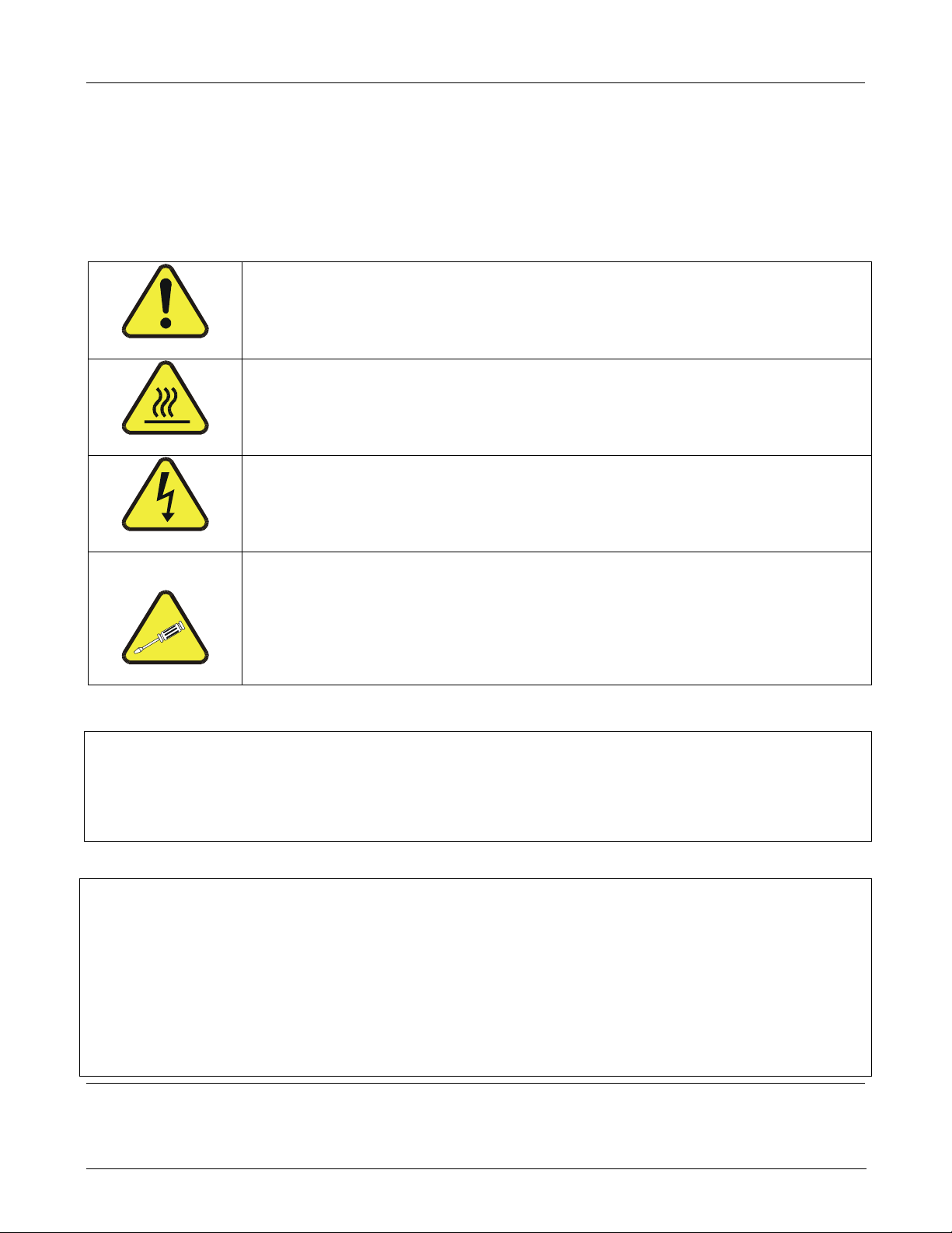
GENERAL SAFETY HAZARD:
Refer to the instructions for details on the specific hazard.
CAUTION:
Hot Surface Warning.
CAUTION:
Electrical Shock Hazard.
TECHNICIAN SYMBOL:
All operations marked with this symbol are to be performed by qualified
maintenance personnel only.
CAUTION
The Model 300EU, CO Analyzer with Auto-Reference, should only be used for the purpose and in the
manner described in this manual. If you use the M300EU in a manner other than that for which it was
intended, unpredictable behavior could ensue with possible hazardous consequences.
NOTE
Technical Assistance regarding the use and maintenance of the
M300EU or any other Teledyne Instruments product
can be obtained by:
Contacting Teledyne Instruments’ Customer Service Departm ent at 800-324-5190
or
Via the internet at http://www.teledyne-api.com/
USER NOTES:
05904 Rev A i

SAFETY MESSAGES M300EU
Addendum to M300E/EM Manual P/N 04288
USER NOTES:
ii 05904 Rev A

M300EU TABLE OF CONTENTS
Addendum to M300E/EM Manual P/N 04288
TABLE OF CONTENTS
1. INTRODUCTION....................................................................................................................................................................III
1.1. Reference Numbering convention .................................................................................................................................... 1
1.2. M300EU Overview ...........................................................................................................................................................1
2. SPECIFICATIONS, APPROVALS AND WARRANTY ...........................................................................................................3
2.1. Specifications ................................................................................................................................................................... 3
2.2. EPA Equivalency Designation ..........................................................................................................................................4
2.3. CE Mark Compliance .......................................................................................................................................................4
2.4. Warranty........................................................................................................................................................................... 4
3. GETTING STARTED ..............................................................................................................................................................4
3.1. Unpacking the M300EU....................................................................................................................................................5
3.2. M300EU analyzer Layout .................................................................................................................................................5
3.3. Electrical Connections ......................................................................................................................................................6
3.3.1. Power Connection .................................................................................................................................................... 6
3.3.2. Analog Output Connections......................................................................................................................................7
3.3.3. Connecting the Status Outputs.................................................................................................................................8
3.4. Initial Operation of the M300EU .......................................................................................................................................9
3.4.1. Startup and Warm up of the M300EU.......................................................................................................................9
3.4.2. Warning Messages ...................................................................................................................................................9
3.4.3. Functional Check ....................................................................................................................................................10
3.5. Initial Calibration.............................................................................................................................................................11
3.5.1. Pre-Calibration Stabilization ...................................................................................................................................11
3.5.2. Basic CO Calibration SETUP .................................................................................................................................11
3.5.2.1. Calibration Gases ...........................................................................................................................................11
3.5.3. Basic CO Calibration Procedure ............................................................................................................................. 12
4. FREQENTLY ASKED QUESTIONS & GLOSSARY ............................................................................................................13
5. OPTIONAL HARDWARE AND SOFTWARE.......................................................................................................................15
5.1. Calibration Valve Options for the M300EU ..................................................................................................................... 16
5.1.1. Zero Span Valves (OPT 50A) ................................................................................................................................. 16
5.1.2. Zero Span Valves with IZS (OPT 51B) ................................................................................................................... 17
5.1.3. Zero Span Valves with IZS and Shutoff VALVE (OPT 51B) ...................................................................................18
6. M300EU OPERATING INSTRUCTIONS..............................................................................................................................19
6.1. Summary of differences between operating the M300EU and the M300E/EM analyzers. ............................................. 19
6.2. Operating Modes............................................................................................................................................................20
6.2.1. Auto-Reference Mode (AREF)................................................................................................................................21
6.2.2. Test Functions ........................................................................................................................................................ 22
6.3. SETUP Æ RNGE: Analog Output Reporting Range Configuration ................................................................................ 23
6.3.1. Physical Range versus Analog Output Reporting Ranges...................................................................................... 23
6.3.2. Analog Output Ranges for CO Concentration......................................................................................................... 23
6.3.3. RNGE Æ MODE Æ SNGL: Configuring the M300EU analyzer for Single Range Mode.........................................25
6.3.4. RNGE Æ MODE Æ DUAL: Configuring the M300EU analyzer for Dual Range Mode .......................................... 26
6.3.5. RNGE Æ MODE Æ AUTO: Configuring the M300EU analyzer for Auto Range Mode ........................................... 27
6.3.6. SETUP Æ RNGE Æ UNIT: Setting the Reporting range Unit Type ........................................................................ 28
6.4. SETUP Æ MORE Æ AREF: Configuring and Performing Auto-Reference Measurements ............................................ 29
6.4.1. Adjusting the A-REF Mode Cycle Time ..................................................................................................................29
6.4.2. Forcing an Auto-Reference measurement..............................................................................................................30
6.5. SETUP Æ MORE Æ VARS: Internal Variables (VARS) ................................................................................................. 32
6.6. SETUP Æ MORE Æ DIAG: Using the Diagnostics Functions ....................................................................................... 33
6.7. Analog Output Configuration .......................................................................................................................................... 34
6.7.1. Analog I/O Configuration ........................................................................................................................................34
6.7.2. Calibration of the Analog Outputs ...........................................................................................................................37
6.7.3. Selecting a Test Channel Function for Output A4................................................................................................... 38
6.7.4. Hessen Protocol ..................................................................................................................................................... 39
7. CALIBRATION PROCEDURES ...........................................................................................................................................41
8. EPA PROTOCOL CALIBRATION........................................................................................................................................43
9. INSTRUMENT MAINTENANCE...........................................................................................................................................45
9.1. Perfoming an Auto-Reference Measurement after maintenance.................................................................................... 45
10. THEORY OF OPERATION.................................................................................................................................................49
10.1. Measurement Method...................................................................................................................................................49
10.1.1. Auto-reference Ratio............................................................................................................................................. 49
10.2. Pneumatic Operation.................................................................................................................................................... 50
10.2.1. The A-REF Valve assembly.................................................................................................................................. 50
10.2.2. The Nafion
®
Dryer. ...............................................................................................................................................51
05904 Rev A i

TABLE OF CONTENTS M300EU
Addendum to M300E/EM Manual P/N 04288
10.3. Electronic Operation.....................................................................................................................................................53
10.3.1. Overview............................................................................................................................................................... 53
10.3.2. The Relay PCA .....................................................................................................................................................54
10.3.2.1. Temperature Control of the Convection Oven............................................................................................... 54
10.3.2.2. Oven Heaters AC Power Configuration ........................................................................................................ 55
10.3.2.3. Status LED’s ................................................................................................................................................. 56
10.3.3. Motherboard ......................................................................................................................................................... 56
10.3.3.1. A to D Conversion.........................................................................................................................................56
10.3.3.2. Sensor Inputs................................................................................................................................................ 56
10.3.4. Power Distribution.................................................................................................................................................57
11. TROUBLESHOOTING & REPAIR.....................................................................................................................................59
11.1. General Notes ..............................................................................................................................................................59
11.2. Fault Diagnosis with Warning Messages......................................................................................................................60
11.2.1. Fault Diagnosis with Test Functions ..................................................................................................................... 62
11.2.2. Relay Board Status LED’s .................................................................................................................................... 64
11.3. Gas flow problems........................................................................................................................................................ 65
11.4. Other Performance Problems.......................................................................................................................................65
11.4.1. Unexplained drift................................................................................................................................................... 65
11.5. Subsystem Chechout ...................................................................................................................................................66
11.5.1. Relay Board ..........................................................................................................................................................66
11.5.2. Motherboard ......................................................................................................................................................... 66
11.5.2.1. A/D Functions ...............................................................................................................................................66
11.6. Technical Assistance.................................................................................................................................................... 67
LIST OF FIGURES
Figure 3-1: M300EU Internal Layout ................................................................................................................5
Figure 3-2: M300EU Internal Gas Flow............................................................................................................6
Figure 3-3: M300EU Analog Output Connector ...............................................................................................7
Figure 5-1: M300EU Internal Pneumatic Flow– Zero/Span Valves with Zero Scrubber (OPT 50A) .............16
Figure 5-2: M300EU Internal Pneumatic Flow– Zero/Span Valves with IZS (OPT 51B)...............................17
Figure 5-3: M300EU Internal Pneumatic Flow– Zero/Span Valves with IZS & Shutoff Valve (OPT 51C).....18
Figure 6-1: Typical Front Panel Display during A-REF Mode........................................................................21
Figure 6-2: Analog Output Connector Pin Out ...............................................................................................23
Figure 10-1: M300EU Gas flow during Auto-Reference Measurements..........................................................49
Figure 10-2: Auto-Reference Measurement Cycle...........................................................................................50
Figure 10-3: Semi-Permeable Membrane Drying Process ..............................................................................51
Figure 10-4: M300EU Electronic Overview Block Diagram .............................................................................53
Figure 10-5: M300EU Heating Control Block Diagram ....................................................................................54
Figure 10-6: M300EU Oven Heater Configuration Jumpers............................................................................55
Figure 10-7: M300EU Oven Heater Configuration Circuit................................................................................55
Figure 10-8: M300EU Distribution Block Diagram ...........................................................................................57
LIST OF TABLES
Table 2-1: M300EU Basic Unit Specifications ................................................................................................3
Table 3-1: Analog Output Data Type Default Settings....................................................................................7
Table 3-2: Analog Output Pin Outs .................................................................................................................8
Table 3-3: Status Output Pin Assignments.....................................................................................................8
Table 3-4: Possible Warning Messages at Start-Up.......................................................................................9
Table 5-1: Possible Warning Messages at Start-Up.....................................................................................15
Table 6-1: M300EU Operating Modes ..........................................................................................................20
Table 6-2: Test Functions Defined................................................................................................................22
Table 6-3: Test Functions Defined................................................................................................................32
Table 6-4: M300EU Diagnostic (DIAG) Submenus.......................................................................................33
Table 6-5: DIAG - Analog I/O Functions .......................................................................................................34
Table 6-6: Test Channels Functions Available on the M300EU’s Analog Output ........................................38
ii 05904 Rev A

M300EU TABLE OF CONTENTS
Addendum to M300E/EM Manual P/N 04288
Table 6-7: M300EU Hessen GAS ID List......................................................................................................39
Table 6-8: Default Hessen Status Bit Assignments ......................................................................................40
Table 7-1: AUTOCAL Modes ........................................................................................................................42
Table 9-1: M300EU Test Function Record ...................................................................................................47
Table 10-1: Auto-Reference Valve Operating States .....................................................................................51
Table 10-2: Relay Board Status LED’s ...........................................................................................................56
Table 11-1: Warning Messages - Indicated Failures ......................................................................................60
Table 11-2: Test Functions - Indicated Failures..............................................................................................62
Table 11-3: Relay Board Status LED Failure Indications ...............................................................................64
Table 11-4: Relay Board Control Devices.......................................................................................................66
LIST OF APPENDICES
APPENDIX A – M300EU VERSION SPECIFIC SOFTWARE DOCUMENTATION
APPENDIX A-1: Model 300EU Software Menu Trees, Revision K.6
APPENDIX A-2: Model 300EU Setup Variables Available Via Serial I/O, Revision K.6
APPENDIX A-3: Model 300EU Warnings and Test Measurements via Serial I/O, Revision K.6
APPENDIX A-4: Model 300EU Signal I/O Definitions, Revision K.6
APPENDIX B – M300EU SPARE PARTS LIST
APPENDIX C - REPAIR QUESTIONNAIRE – M300EU
APPENDIX D - ELECTRONIC SCHEMATICS
USER NOTES:
05904 Rev A iii

TABLE OF CONTENTS M300EU
Addendum to M300E/EM Manual P/N 04288
USER NOTES:
iv 05904 Rev A

M300EU INTRODUCTION
Addendum to M300EU Manual - P/N 04288
1. INTRODUCTION
This addendum is based on the M300E/EM Operators Manual (P/N 04288). It is intended as a supplement to
the M300E/EM manual (P/N 04288) and provides an overview of the instrument operation and specific details
regarding those areas where the M300EU is different in design or operating method from the M300E.
In most ways the M300EU is identical to the M300E/EM in design and operation, therefore most of the basic set
up information, operating instructions as well as calibration, maintenance, troubleshooting and repair methods
are the same and can be found in the M300E/EM manual (P/N 04288).
1.1. REFERENCE NUMBERING CONVENTION
Unless otherwise specified, chapter, section, figure and table reference numbers referred to within this text are
relative to this document.
• EXAMPLE: “Table 2-1” refers to the figure, within this document, labeled as 2-1.
• Additionally, in the electronic version(s) of this manual references internal to this document will be active
links to that section, figure or table.
References to chapters, sections, figures and tables in the original document will be labeled as such and will not
be an active link.
• EXAMPLE: “Figure 6.1 of the M300E/EM Operators Manual (P/N 04288)”.
1.2. M300EU OVERVIEW
The information contained in this addendum is relevant to M300EU analyzers running: SOFTWARE
REVISION K.6. Some or all of the information may not be applicable to earlier or later revisions of
The software revision your analyzer is running is displayed in the upper left-hand corner of the display
any time the instrument is in SETUP mode.
The model 300EU is a close derivative of the M300E/EM CO Analyzer, however its higher sensitivity require
some changes its design and operation.
The primary differences between the M300EU and the M300E/EM analyzers are:
• INTERFERENT REJECTION: Periodically the sample gas stream is routed through an internal CO
scrubber allowing the instrument to make a measurement of the sample gas completely free of CO; the
measurement made during this auto-reference period (A-REF) is subtracted from the sample
concentration measurement. This corrects for instrument drift, ambient temperature changes and
changing CO
• OPERATING METHOD: An additional operating mode is added allowing the user to manipulate several
parameters associated with the A-REF measurement cycle.
• SAMPLE GAS CONDITIONING: A Nafion
humidity changes in the sample gas.
levels in the sample gas.
2
NOTE
software.
®
drier is used to dry the sample and alleviate any effects from
• IR OPTICS: The objective and field mirrors on the optical bench are gold plated. This maximizes their
reflectivity and increasing the amount of IR light reaching the detector and improving the optical bench’s
signal-to-noise performance.
• PNEUMATIC OPERATION: The flow rate is higher. It has a 1.8 LPM nominal flow rate. The flow
sensor is rated to 6 LPM.
• MECHANICAL DESIGN: The optical bench is placed in a temperature-controlled, convection-heated
oven. This dramatically reduces instrument noise and temperature related drift.
05904 Rev A 1

INTRODUCTION M300EU
Addendum to M300E/EM Manual P/N 04288
USER NOTES:
2 05904 Rev A

M300EU SPECIFICATIONS, APPROVALS AND WARRANTY
(Addendum to M300EU Manual - P/N 04145)
2. SPECIFICATIONS, APPROVALS AND
WARRANTY
2.1. SPECIFICATIONS
Table 2-1: M300EU Basic Unit Specifications
Ranges User selectable to any full scale range from 0-100 ppb to 0-100 ppm
Measurement Units ppb, ppm, µg/m3, mg/m3 (user selectable)
Zero Noise ≤ 10 ppb RMS
Span Noise < 0.5% of reading RMS over 5 ppm
Lower Detectable Limit < 20 ppb
Zero Drift (24 hours) < 20 ppb
Zero Drift (7 days) < 20 ppb
Span Drift (24 hours) < 0.5% of reading
Span Drift (7 days) < 1% of reading
Linearity Better than 1% of Range
Precision 0.5% reading1,
Lag Time <10 sec
Rise/Fall Time <30 sec to 95%
Sample Flow Rate 1800 cm3/min. ± 20%
Temperature Range
15 - 35°C operating
Humidity Range 0-95% RH, Non-Condensing
Voltage Coefficient < 0.05 % of reading per V
Dimensions (HxWxD) 7" x 17" x 23.5" (178 mm x 432 mm x 597 mm)
Weight 50 lb (22.7 kg)
AC Power
100V 50/60 Hz (3.25A), 115 V 60 Hz (3.0A),
220 – 240 V 50/60 Hz (2.5A)
Environmental Conditions Installation Category (Over voltage Category) II Pollution Degree 2
Analog Outputs Three (3) Outputs
Analog Output Ranges
100 mV, 1 V, 5 V, 10 V, 2-20 or 4-20 mA isolated current loop.
All Ranges with 5% Under/Over Range
Analog Output Resolution 1 part in 4096 of selected full-scale voltage
Status Outputs 8 Status outputs from opto-isolators
Control Inputs 6 Control Inputs, 2 defined, 4 spare
I/O
One (1) RS-232; One (1) RS-485/RS-232/Ethernet
Baud Rate : 300 - 115200
Certifications CE: EN61010-1:90 + A1:92 + A2:95, EN61326 - Class A
1
As defined by the USEPA
2
At constant temperature and voltage
3
Or 10 ppb, whichever is greater
4
Or 10 ppb, whichever is greater
5
Above 1 ppm range, otherwise 20 ppb for lower ranges
1, 6
1, 3
1
2
2
4
2 4
5
5
1
1
05514 Rev A1 3

SPECIFICATIONS, APPROVALS AND WARRANTY M300EU
Addendum to M300E/EM Manual P/N 04288
2.2. EPA EQUIVALENCY DESIGNATION
The M300EU has not been certified by the EPA as an equivalent method at the time of this writing however it is
anticipated that the M300EU will qualify as Reference Method Number EQSA-0495-100 per 40 CFR Part 53 in
the near future.
Therefore the information found in Section 2.2 of the M300E/EM Operators Manual (P/N 04288) is applicable to
the M300EU with the following exception(s):
Range: Any range from 100 ppb to 100 ppm.
Ambient temperature range of 15 to 35°C.
Sample filter: Equipped with PTFE filter element in the external filter assembly.
Sample flow of 1800 ± 360 cm
Calibration valve options.
3
/min at sea level.
a) Option 50A –
b) Option 51B –
c) Option 51C –
Zero/Span Valves;
Zero / Span Valves with Zero Scrubber.
Zero / Span Valves with Zero Scrubber & Shut-off Valves
2.3. CE MARK COMPLIANCE
See Section 2.3 of the M300E/EM manual (P/N 04288)
2.4. WARRANTY
See Section 2.4 of the M300E/EM manual (P/N 04288)
USER NOTES:
4 05831 Rev. 01
M300EU GETTING STARTED
V
(Addendum to M300EU Manual - P/N 04145)
3. GETTING STARTED
3.1. UNPACKING THE M300EU
Unpack the M300EU as per the directions in Section 3.1 of the M300E/EM manual (P/N 04288), with the
exception that there are no shipping screws.
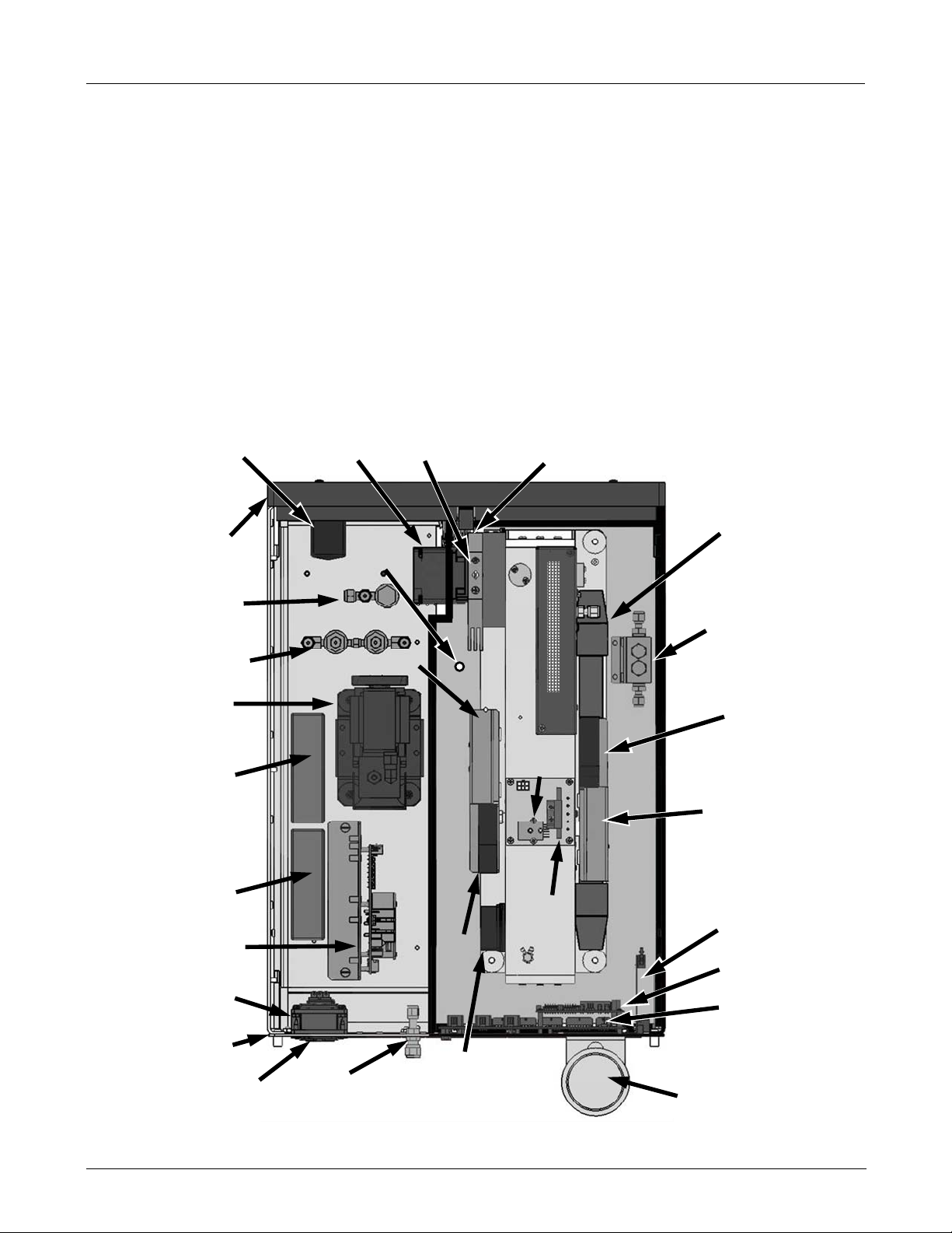
3.2. M300EU ANALYZER LAYOUT
The front panel of the M300EU is identical to that of the M300E/EM (see Figure 3-1 of the M300E/EM Operators
Manual (P/N 04288). The Rear Panel is also very similar to that of the M300E/EM, the only difference being that
the instrument’s particulate filter is mounted externally on the upper left side of the rear panel rather than
internally as on the M300E/EM.
On the other hand, the internal layout of the M300EU is quite different from the M300E/EM. Most of these
differences are related to the need to create a thermally insulated, convection-heated oven in which the optical
bench temperature is raised and maintained at a high and very stable temperature. Additionally there is a multitube, high flow Nafion
Optional
Shutoff Valve
Optional
Zero /Sample/Cal
Valves
+12 VDC
Power Supply
®
dryer that removes moisture from the sample gas.
On/Of Switch &
Circuit Breaker
Front
Panel
Internal
Pump
GFC Wheel
Motor
Oven
Temperature
Sensor
Oven Heater 1
IR Source
GFC Wheel Housing
& Heat Sync
SYNC/DEMOD PCA
OPTICAL BENCH
Gas
Pressure
Sensor
®
Nafion
Dryer
Auto-Ref
& CO Scrubber
Assembly
alve
Fan
Oven Heater 2
±5 VDC
Power Supply
Relay PCA
AC Power
Receptacle
(under fan)
REAR
Panel
Main
Cooling Fan
Gas inlets &
Outlets
INSULATED OVEN AREA
Oven
Fan
Motherboard
Stabilization Fan
Gas
Flow
Sensor
Optional
Ethernet
PCA
CPU
Motherboard
Particulate Filter
Figure 3-1: M300EU Internal Layout
05514 Rev A1 5
GETTING STARTED M300EU
Addendum to M300E/EM Manual P/N 04288
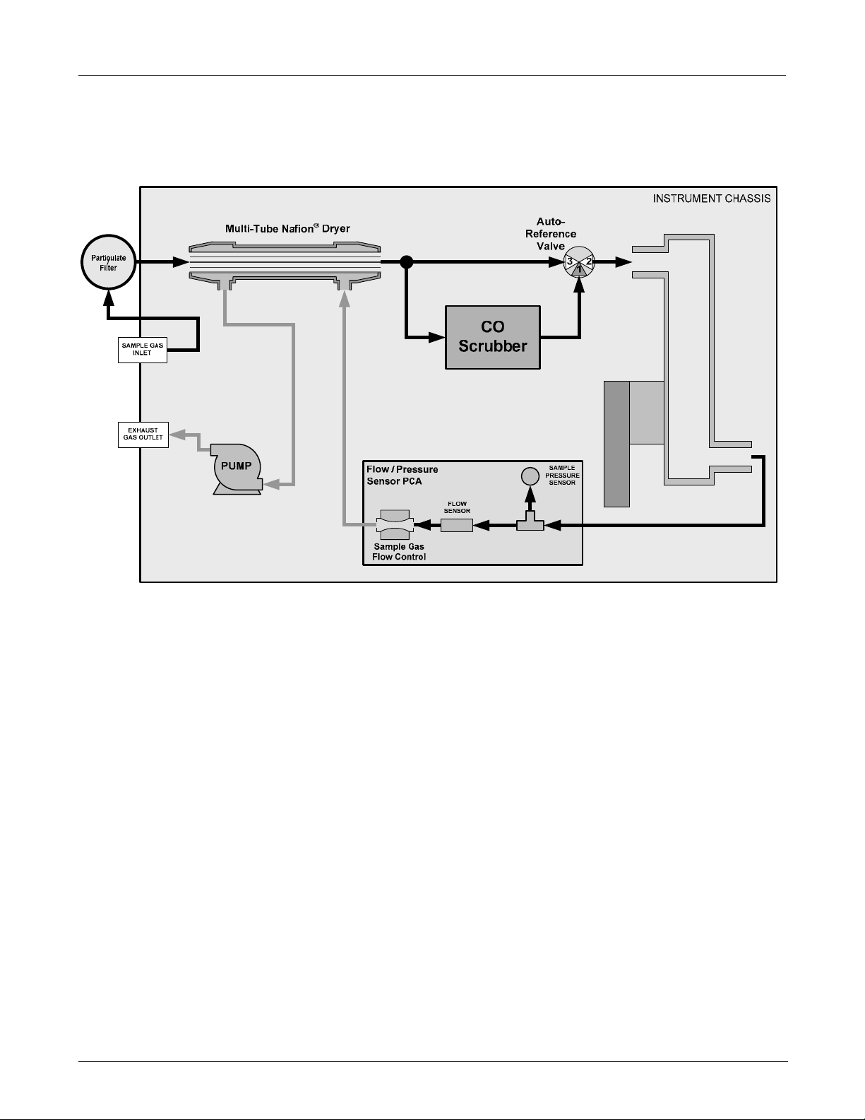
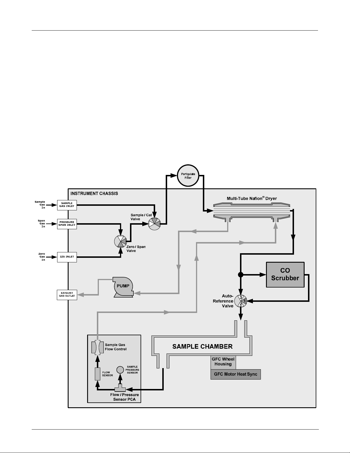
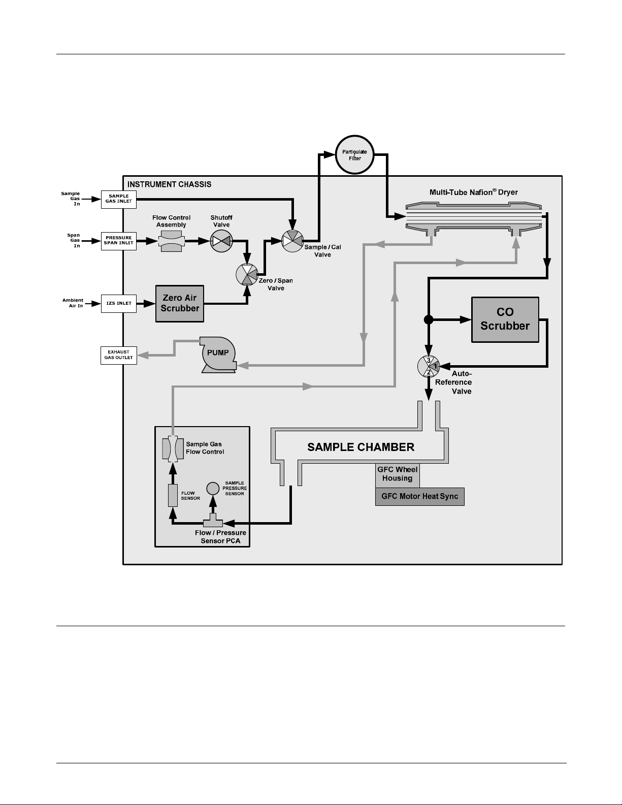
The pneumatic flow of the M300EU is different from the M300E/EM in two ways:
• The addition of a high-flow multi-tube Nafion
®
dryer.
• An additional gas path that passes the sample gas though a CO
reference cycle.
scrubber used during the auto-
SAMPLE CHAMBER
Housing
GFC Wheel
GFC Motor Heat Sync
Figure 3-2: M300EU Internal Gas Flow
3.3. ELECTRICAL CONNECTIONS
The information found in Section 3.1.2 of the M300E/EM Operators Manual (P/N 04288) is applicable to the
M300EU with the following exceptions.
3.3.1. POWER CONNECTION
The information found in Section 3.1.2.1 of the M300E/EM manual (P/N 04288) is correct for the M300EU.
6 05831 Rev. 01

M300EU GETTING STARTED
(Addendum to M300EU Manual - P/N 04145)
3.3.2. ANALOG OUTPUT Connections
The analog outputs for the M300EU are different from those of the M300E/EM. Unlike the M300E/EM which can
include options for measuring both O
not require the fully configurable version of the analog outputs. The following information replaces that found in
Section 3.1.2.2 of the M300E/EM Operators Manual (P/N 04288).
The M300EU is equipped with several analog output channels accessible through a connector on the back panel
of the instrument.
• Channels A1 and A2 output a signal that is proportional to the CO concentration of the sample gas.
• The default analog output voltage setting of these channels is 0 to 5 VDC with a reporting range of 0
to 500 ppb.
• An optional Current Loop output is available for each.
• The output labeled A4 is special. It can be set by the user to output any one a variety of diagnostic test
functions.
• The default analog output voltage setting of these channels is also 0 to 5 VDC.
• See Section 6.2.2 for a list of available functions.
• There is NO optional Current Loop output is available for Channel A4.
and CO, the M300EU is a single gas analyzer (CO) and therefore does
2
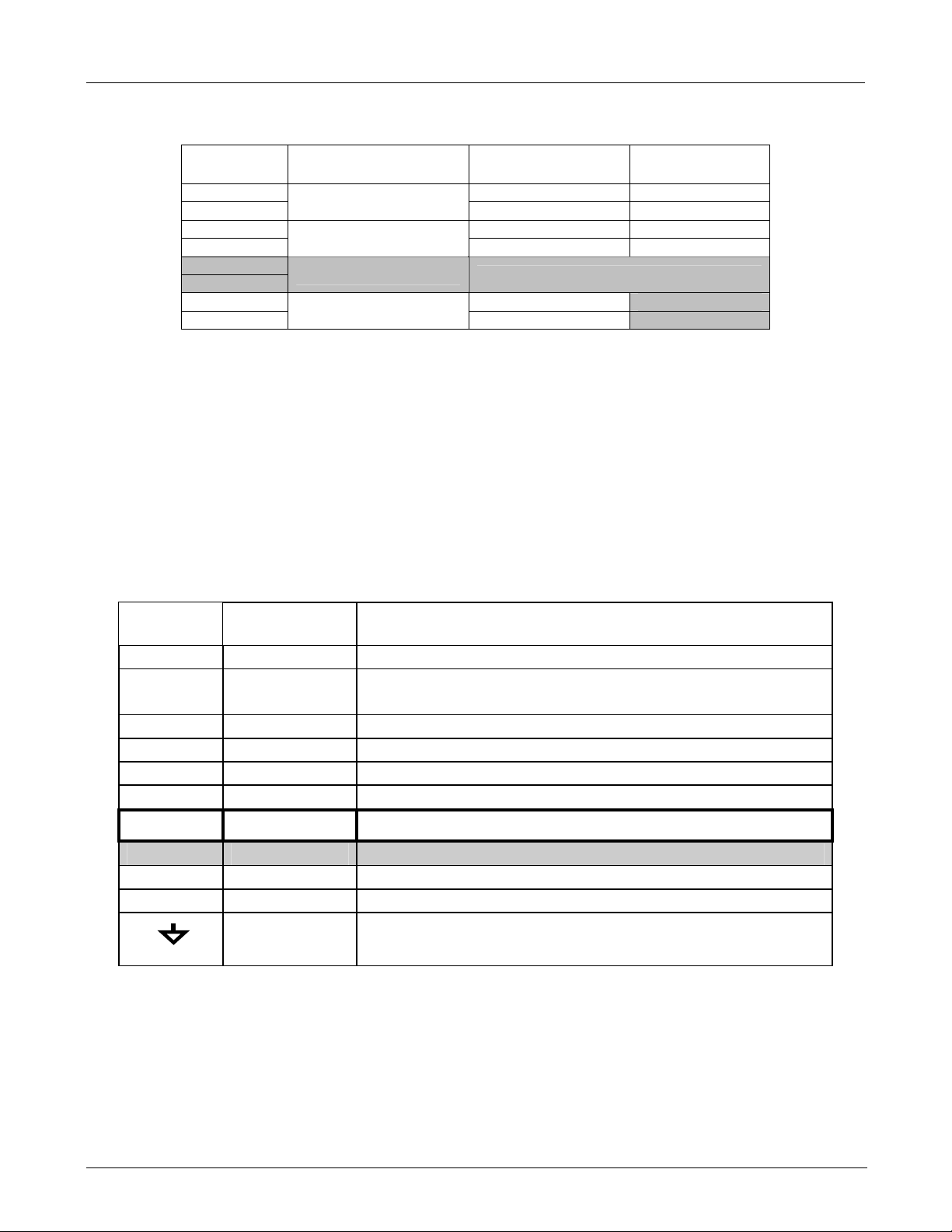
The following table lists the default settings for each of these channels.
Table 3-1: Analog Output Data Type Default Settings
PARAMETER CHANNEL DEFAULT SETTING
DATA TYPE
RANGE
OVERRANGE
REC OFS
AUTO CAL.
CALIBRATED
OUTPUT
1
See Table A-6 of M300E/EM Appendix A for definitions of these iDAS data types
2
Optional current loop outputs are available for analog output channels A1& A2.
1
A1 A2 A3 A4
CONC1 CONC2
0 – 5 VDC
0 mVDC
2
ON
ON
NO
ON
Not
Available
1
TEST
CHANNEL
To access these signals attach a strip chart recorder and/or data-logger to the appropriate analog output
connections on the rear panel of the analyzer. Pin-outs for the analog output connector are:
A1 A2 A3 A4
+ - + - + - + -
ANALOG OUT
Figure 3-3: M300EU Analog Output Connector
05514 Rev A1 7
GETTING STARTED M300EU
Addendum to M300E/EM Manual P/N 04288
Table 3-2: Analog Output Pin Outs
Pin Analog Output
1 V Out I Out +
2
3 V Out I Out +
4
5
6
7 V Out Not Available
8
A1
A2
A3
A4
Standard Voltage
Output
Ground I Out -
Ground I Out -
NOT USED
Ground Not Available
3.3.3. CONNECTING THE STATUS OUTPUTS
The information found in Section 3.1.2.3 is correct with the following exception:
Table 3-3: Status Output Pin Assignments
Current
Loop Option
Output #
1 SYSTEM OK On if no faults are present.
2
3 HIGH RANGE
4 ZERO CAL On whenever the instruments ZERO point is being calibrated.
5 SPAN CAL On whenever the instruments SPAN point is being calibrated.
6 DIAG MODE On whenever the instrument is in DIAGNOSTIC mode.
7
8 SPARE
D
+
Status
Definition
CONC VALID
On if CO concentration measurement is valid.
If the CO concentration measurement is invalid, this bit is OFF.
On if unit is in high range of DUAL or AUTO Range Modes.
A-REF On whenever the instrument in is A-REF mode.
EMITTER BUSS The emitters of the transistors on pins 1-8 are bussed together.
DC POWER + 5 VDC
Digital Ground The ground level from the analyzer’s internal DC Power Supplies.
Condition
8 05831 Rev. 01

M300EU GETTING STARTED
(Addendum to M300EU Manual - P/N 04145)
3.4. INITIAL OPERATION OF THE M300EU
NOTE
The analyzer’s cover must be installed and securely fastened to ensure that the convection oven portion
of the internal layout is capable of properly creating and controlling temperatures of the analyzer’s
optical bench.
3.4.1. STARTUP AND WARM UP OF THE M300EU
The process for starting and warming up the M300EU is identical to that described in Sections 3.2.1 and 3.2.2 of
the M300E/EM Operators Manual (P/N 04288) except:
• It is best to alloy the M300EU to operate uninterrupted for at least 2 hours to allow the temperature of all
areas of the convection oven area to equalize.
3.4.2. WARNING MESSAGES
The information found in Section 3.2.3 of the M300E/EM Operators Manual (P/N 04288) is applicable to the
M300EU with the following exception(s)
Table 3-4: Possible Warning Messages at Start-Up
MESSAGE MEANING
ANALOG CAL WARNING
AZERO WARN 1.001
BENCH TEMP WARNING
BOX TEMP2 WARNING
CANNOT DYN SPAN
CANNOT DYN ZERO
CONFIG INITIALIZED
DATA INITIALIZED
FRONT PANEL WARN
OVEN TEMP
WARNING
PHOTO TEMP WARNING
REAR BOARD NOT DET
RELAY BOARD WARN
SAMPLE FLOW WARN
SAMPLE PRESS WARN
SAMPLE TEMP WARN
SOURCE WARNING
SYSTEM RESET
WHEEL TEMP WARNING
The instrument's A/D circuitry or one of its analog outputs is not calibrated.
Auto-reference ratio below the specified limits.
Optical bench temperature is outside the specified limits.
The temperature inside the M300EU chassis is outside the specified
limits (Replaces BOX TEMP WARNING)
Remote span calibration failed while the dynamic span feature was set to turned
on
Remote zero calibration failed while the dynamic zero feature was set to turned on
Configuration was reset to factory defaults or was erased.
iDAS data storage was erased.
Firmware is unable to communicate with the front panel.
The temperature of the insulated convection oven area of the
analyzer is outside of the specified limits.
Photometer temperature outside of warning limits specified by
PHOTO_TEMP_SET variable.
The CPU is unable to communicate with the motherboard.
The firmware is unable to communicate with the relay board.
The flow rate of the sample gas is outside the specified limits.
Sample pressure outside of operational parameters.
The temperature of the sample gas is outside the specified limits.
The IR source may be faulty.
The computer was rebooted.
The Gas Filter Correlation wheel temperature is outside the specified limits.
05514 Rev A1 9
GETTING STARTED M300EU
Addendum to M300E/EM Manual P/N 04288
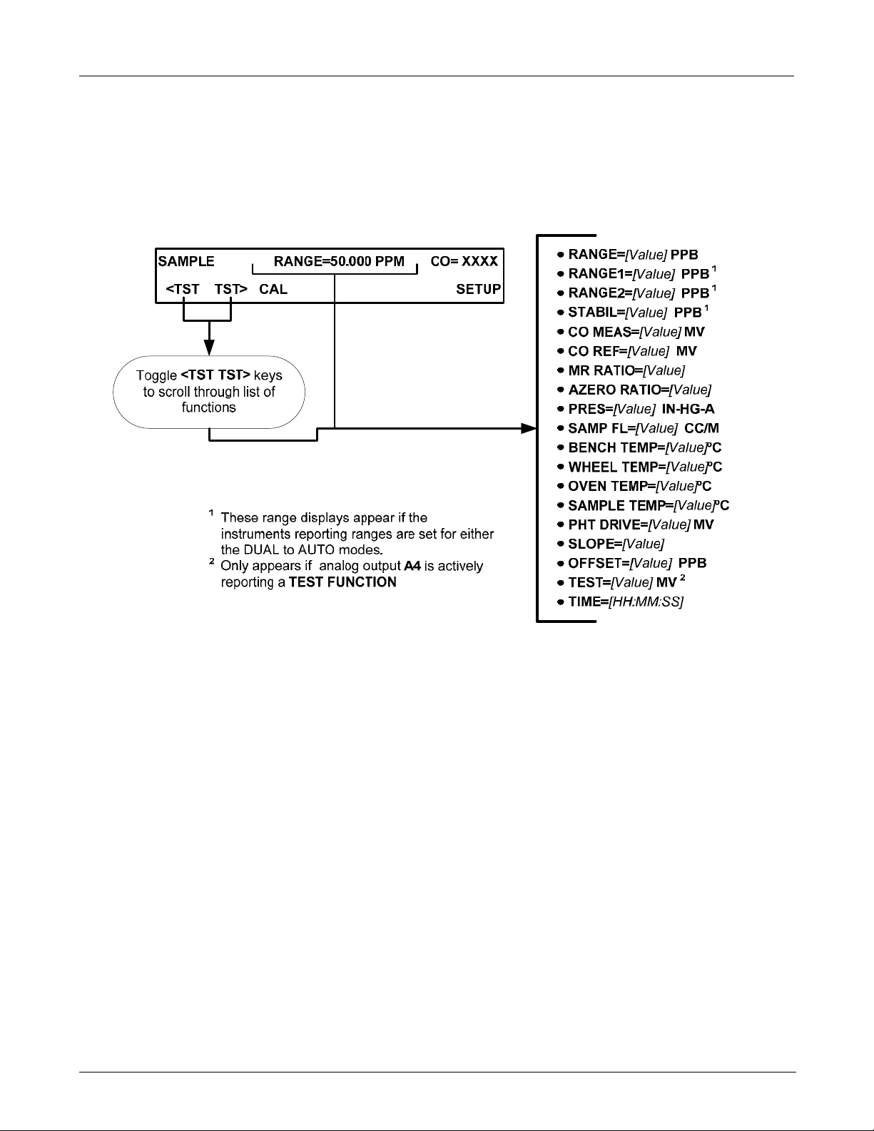
3.4.3. FUNCTIONAL CHECK
The information found in Section 3.2.4 of the M300E/EM Operators Manual (P/N 04288) regarding performing an
initial functional check of the analyzer is applicable to the M300EU with the following exception(s).
The Test functions available from the front panel of the M300EU are:
10 05831 Rev. 01

M300EU GETTING STARTED
(Addendum to M300EU Manual - P/N 04145)
3.5. INITIAL CALIBRATION
3.5.1. PRE-CALIBRATION STABILIZATION
Before initially calibrating the M300EU it must be allowed to operate for a minimum of 12 hours.
After this stabilization period is complete and just prior to performing the initial calibration, manually initiate an
auto-reference measurement by following the instructions in Section 6.4.
3.5.2. BASIC CO CALIBRATION SETUP
NOTE
The following procedure assumes that the instrument does not have any of the available Zero/Span
Valve Options installed.
To perform the following calibration you must have sources for zero air and span gas available for input into the
sample port on the back of the analyzer. See Section 3.1.3 of the M300E/EM Operators Manual (P/N 04288) for
instructions for connecting these gas sources.
NOTE
All Gas lines should be PTFE (Teflon), FEP, glass, stainless steel or brass
3.5.2.1. Calibration Gases
The information found in Section 3.1.3.2 of the M300E/EM Operators Manual (P/N 04288) is applicable to the
M300EU with the following exception:
ZERO AIR
A gas that is similar in chemical composition to the earth’s atmosphere but scrubbed of all components
that might affect the analyzers readings, in this case CO and water vapor.
For the M300EU this gas MUST include at least 5% O
analyzer’s CO scrubber).
For analyzers without an IZS or external zero air scrubber option, a zero air generator such as the
Teledyne Instruments Model 701 can be used.
(required for the proper operation of the
2
NOTE
The zero air generator MUST be equipped with a hydrocarbon (HC) & CO scrubber option.
For the Teledyne Instruments M701, this is Option 2B
05514 Rev A1 11

GETTING STARTED M300EU
Addendum to M300E/EM Manual P/N 04288
3.5.3. BASIC CO CALIBRATION PROCEDURE
The initial calibration should be carried out using the same reporting range set up as used during the analyzer’s
factory calibration. This will allow you to compare your calibration results to the factory calibration as listed on
the Final Test and Validation Data Sheet.
Because the M300EU’s analog output setup differs from that of the M300E/EM and because the M300EU
cannot have be modified to include the optional CO
the initial Calibration procedure as described in Section 3.3 of the M300E/EM Operators Manual (P/N 04288).
These are:
• STEP 1 - SET LIMITS:
• Reporting Range Limit should be set to 50.000 ppm.
• STEP 2 – DILUTION RATIO:
• Ignore this step
• STEP 3 – SET CO SPAN GAS CONCENTRATION
• The CO span gas concentration should be 40.000 ppm
• STEP 4 – ZERO/SPAN CALIBRATION
or O2 sensor packages, there are some minor differences in
2
• Set the display to show the STABILITY test function.
• There is no GAS TO CAL step because the M300EU cannot be modified to include the O
sensor packages.
Ignore Sections 3.3.2 and 3.3.3 of the M300E/EM Operators Manual (P/N 04288) since they relate to sensor
options not available on the M300EU.
and CO2
2
USER NOTES:
12 05831 Rev. 01

M300EU FREQENTLY ASKED QUESTIONS & GLOSSARY
(Addendum to M300EU Manual - P/N 04145)
4. FREQENTLY ASKED QUESTIONS & GLOSSARY
The information found in Chapter 4 of the M300E/EM Operators Manual (P/N 04288) is applicable to the
M300EU.
USER NOTES:
05514 Rev A1 13

FREQENTLY ASKED QUESTIONS & GLOSSARY M300EU
Addendum to M300E/EM Manual P/N 04288
USER NOTES:
14 05831 Rev. 01
M300EU Optional Hardware and Software
(Addendum to M300EU Manual - P/N 04145)
5. OPTIONAL HARDWARE AND SOFTWARE
The following table lists the optional hardware is available for the M300Ex family of analyzers. There are no
additional options available for the M300EU that are not also available for the M300E/EM.
For descriptions of theses options and their use please see Chapter 5 of the M300E/EM Operators Manual (P/N
04288).
Table 5-1: Possible Warning Messages at Start-Up
OPTION
NO.
10A External Pump 115V/60Hz X X X
10B External Pump 220V/50Hz X X X
10C External Pump 220V/60Hz X X X
10D External Pump 100V/50Hz X X X
10E External Pump 100V/60Hz X X X
13
20A Rack Mount with Chassis Slides - 26" X X X
20B Rack Mount with Chassis Slides - 24" X X X
21 Rack Mount, Ears only (No Slides) X X X
23 Rack Mount for External Pump Pack (No Slides) X X X
29 Carrying Handle (Strap) X X X
41 Isolated 0-20 or 4-20 mA output X X X
42A Expendable Kit for one year operation X X X
50A Zero/Span Valves X X X
51B Zero / Span Valves with Zero Scrubber X X X
51C Zero / Span Valves with Zero Scrubber & Shut-off Valves X X X
60A RS232 Cable DB9F to DB25M X X X
60B RS232 Cable DB9F to DB9F X X X
60C CATS, 7 (2m) RJ-45 X X X
62 RS232 Multidrop X X X
63A Ethernet X X X
63C Multidrop/Ethernet Combo X X X
65A Paramagnetic O2 Sensor X X
67A CO2 Sensor 20% X
67B CO2 Sensor 5% X
67C CO2 Sensor 2000 PPM X
70A Additional Manual X X X
70B Manual on CD X X X
High Voltage Internal Pump 240V/50Hz (E Series non-NOx internal
pump)
DESCRIPTION 300E 300EM 300EU
PUMP PACKS
X X
RACK MOUNTING
RANGE & OUTPUT OPTIONS
EXPENDABLES KITS & SPARES
VALVES AND IZS
COMMUNICATIONS
SECOND SENSORS
MANUALS
05514 Rev A1 15
Optional Hardware and Software M300EU
Addendum to M300E/EM Manual P/N 04288
For assistance with ordering these options, please contact the Sales department of Teledyne – Advanced
Pollution Instruments at:
TOLL-FREE: 800-324-5190
FAX: 858-657-9816
TEL: 858-657-9800
E-MAIL: api-sales@teledyne.com
WEB SITE: www.teledyne-api.com
5.1. CALIBRATION VALVE OPTIONS FOR THE M300EU
The various valve options available on the M300EU are implemented in the same manner as described in the
corresponding sections of the M300E/EM Operators Manual (P/N 04288) with the following exception(s).
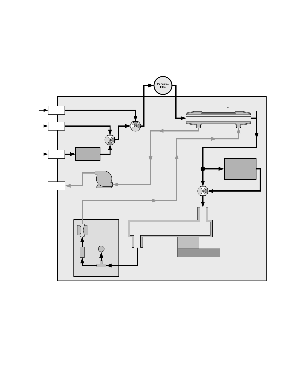
5.1.1. ZERO SPAN VALVES (OPT 50A)
Because of the addition of the auto-reference gas path and the multi-tube Nafion® dryer, the internal pneumatics
gas flow of the M300EU is somewhat different from the M300E/EM. Otherwise, the information found in Section
5.4.3 of the M300E/EM Operators Manual (P/N 04288) is applicable to the M300EU.
Figure 5-1: M300EU Internal Pneumatic Flow– Zero/Span Valves (OPT 50A)
16 05831 Rev. 01
M300EU Optional Hardware and Software
(Addendum to M300EU Manual - P/N 04145)
5.1.2. ZERO SPAN VALVES WITH IZS (OPT 51B)
Because of the addition of the auto-reference gas path and the multi-tube Nafion® dryer, the internal pneumatics
gas flow of the M300EU is somewhat different from the M300E/EM. Otherwise, the information found in Section
5.4.4 of the M300E/EM Operators Manual (P/N 04288) is applicable to the M300EU.
/
INSTRUMENT CHASSIS
Sample
Gas
Span
Gas
Ambient
Air In
In
In
SAMPLE
GAS INLET
PRESSURE
SPAN INLET
IZS INLET
Zero Air
Scrubber
Sample / Cal
Valve
Zero / Span
Valve
Multi-Tube Nafion
Dryer
CO
Scrubber
PUMP
EXHAUST
GAS OUTLET
Sample Gas
Flow Control
FLOW
SENSOR
Flow / Pressure
Sensor PCA
SAMPLE
PRESSURE
SENSOR
SAMPLE CHAMBER
Figure 5-2: M300EU Internal Pneumatic Flow– Zero/Span Valves with IZS (OPT 51B)
Auto-
Reference
Valve
3
1
2
GFC Wheel
Housing
GFC Motor Heat Sync
05514 Rev A1 17
Optional Hardware and Software M300EU
Addendum to M300E/EM Manual P/N 04288
5.1.3. Zero Span Valves with IZS and Shutoff VALVE (OPT 51B)
Because of the addition of the auto-reference gas path and the multi-tube Nafion® dryer, the internal pneumatics
gas flow of the M300EU is somewhat different from the M300E/EM. Otherwise, the information found in Section
5.4.4 of the M300E/EM Operators Manual (P/N 04288) is applicable to the M300EU.
Figure 5-3: M300EU Internal Pneumatic Flow– Zero/Span Valves with IZS & Shutoff Valve (OPT 51C)
USER NOTES:
18 05831 Rev. 01

M300EU M300EU OPERATING INSTRUCTIONS
(Addendum to M300EU Manual - P/N 04145)
6. M300EU OPERATING INSTRUCTIONS
6.1. SUMMARY OF DIFFERENCES BETWEEN OPERATING
THE M300EU AND THE M300E/EM ANALYZERS.
For the most part the operation instruction for the M300EU are the same as those described in Chapter 6 of the
M300E/EM manual (P/N 04288) with the following exceptions:
• There are several additional Test functions related to the optical bench’s convection oven and the AREF cycle (see Section6.2.2).
• There is and additional warning message related to the optical bench’s convection oven (see Section
3.4.2)
• There is an additional operating mode, AREF, which can be used to force the instrument to make an
auto-reference measurement and calculation.
• There are several additional iDAS trigger events and parameters (see Appendix A of this addendum).
• The reporting range setup and configuration of the A1 and A2 analog outputs is different (see Section
6.3).
• The optional O
M300EU. Ignore all references to these in the M300E/EM Operators Manual (P/N 04288) when
operating the M300EU.
• The set of available VARS is different (see Section 6.5.
• The set of submenus available under the DIAG menu is slightly different (see Section 6.6).
and CO2 sensor packages available for the M300E/EM are not available ton the
2
• The set of signals available under the DIAG ÆSIGNAL I/O submenu is different (see Appendix A of this
addendum).
• Because of the difference in how the analog output ranges are implemented between the M300E/EM
and the M300EU, there are some differences in DIAGÆ ANALOG I/O CONFIGURATION submenu
(see Section 6.7.1).
• There are no alarm outputs available of the M300EU. Ignore Section 6.14 of the M300E/EM Operators
Manual (P/N 04288).
• There is an additional STATUS OUTPUT related to the A-REF cycle (see Section 3.3.3).
• The default Hessen protocol gas ID and status flag list is different from that of the M300E/EM (see
Section 6.7.4).
05514 Rev A1 19

M300EU OPERATING INSTRUCTIONS M300EU
Addendum to M300E/EM Manual P/N 04288
6.2. OPERATING MODES
The information found in Section 6.1 of the M300E/EM Operators Manual (P/N 04288) is applicable to the
M300EU with the following exception(s).
The following table supersedes Table 6-2 of the M300E/EM Operators Manual (P/N 04288).
Table 6-1: M300EU Operating Modes
MODE MEANING
The analyzer is currently recording values for CO MEAS and CO ref, while the
A-REF
DIAG
M-P CAL
SAMPLE
SAMPLE A Indicates that unit is in SAMPLE Mode and AUTOCAL feature is activated.
SETUP
1
SPAN CAL A
SPAN CAL M
SPAN CAL R
ZERO CAL A
ZERO CAL M
ZERO CAL R
1
The revision of the Teledyne Instruments software installed in this analyzer will be displayed following the word
SETUP. E.g. “SETUP
2
The various CAL modes allow calibration of the analyzer. Because of their importance, these modes are
described separately in Chapter 7 of the M300E/EM Operators Manual (P/N 04288).
sample gas stream is being routed through the CO scrubber of the autoreference gas path.
One of the analyzer’s diagnostic modes is being utilized.
This is the basic, multi-point calibration mode of the instrument and is activated by pressing
the CAL key.
Sampling normally, flashing indicates adaptive filter is on.
SETUP mode is being used to configure the analyzer (CO sampling will continue during this
process as well as data collection and output).
Unit is performing span cal procedure initiated automatically by the analyzer’s AUTOCAL
2
feature.
2
Unit is performing span cal procedure initiated manually by the user.
Unit is performing span cal procedure initiated remotely via the RS-232, RS-4485 or digital i/o
2
control inputs.
Unit is performing zero cal procedure initiated automatically by the analyzer’s AUTOCAL
2
feature.
2
Unit is performing zero cal procedure initiated manually by the user.
Unit is performing zero cal procedure initiated remotely via the RS-232, RS-4485 or digital I/O
2
control inputs.
G.5”
20 05831 Rev. 01

M300EU M300EU OPERATING INSTRUCTIONS
(Addendum to M300EU Manual - P/N 04145)
6.2.1. AUTO-REFERENCE MODE (AREF)
One of the most significant differences between the M300E/EM and the M300EU analyzers is the auto-reference
measurement feature. In this mode, the analyzer makes special measurements and calculations that are
applied to the CO concentration calculation to dramatically improve interferent rejection as well as compensate t
for changes in ambient temperature of the sample gas and age related drift of the optical bench components
(see Section 10.1.1 for detailed information about how and when this A-REF feature occurs).
When in A-REF mode, the analyzer:
• Freezes the CO concentration reading displayed on the front panel and output via the analog outputs or
COM Ports.
• Displays the Message AUTO-REF in the mode filed of the analyzer’s front panel.
• Sets the A-REF status output (pin-7 on the status output connector) to high.
Mode Field
AUTO-REF RANGE = 50.000 PPM CO =12.430
<TST TST> CAL CALZ CALS SETUP
Figure 6-1: Typical Front Panel Display during A-REF Mode
NOTE:
Initiating a calibration through either the keyboard, the COMM ports or digital control inputs terminates
the A-REF mode.
Also, when the instrument is in calibration mode, the A-REF mode is suppressed until the instrument
exits calibration mode.
See Section 6.4 for information about changing the A-REF cycle time or manually initiating an auto-reference
measurement.
05514 Rev A1 21
 Loading...