

Page 1

MANUAL ADDENDUM
MODEL 201A
AMMONIA ANALYZER
TELEDYNE ADVANCED POLLUTION INSTRUMENTATION
Copyright 2005 T-API Inc.
(T-API)
9480 CARROLL PARK DRIVE
SAN DIEGO, CA 92121-5201
TOLL-FREE: 800-324-5190
FAX: 858-657-9816
TEL: 858-657-9800
E-MAIL: api-sales@teledyne.com
WEB SITE:
12 September, 2005
www.teledyne-api.com
04689
REV. B1
Page 2
Teledyne API Model 201A NH3 Analyzer Instruction Manual, 04689, Rev. B1
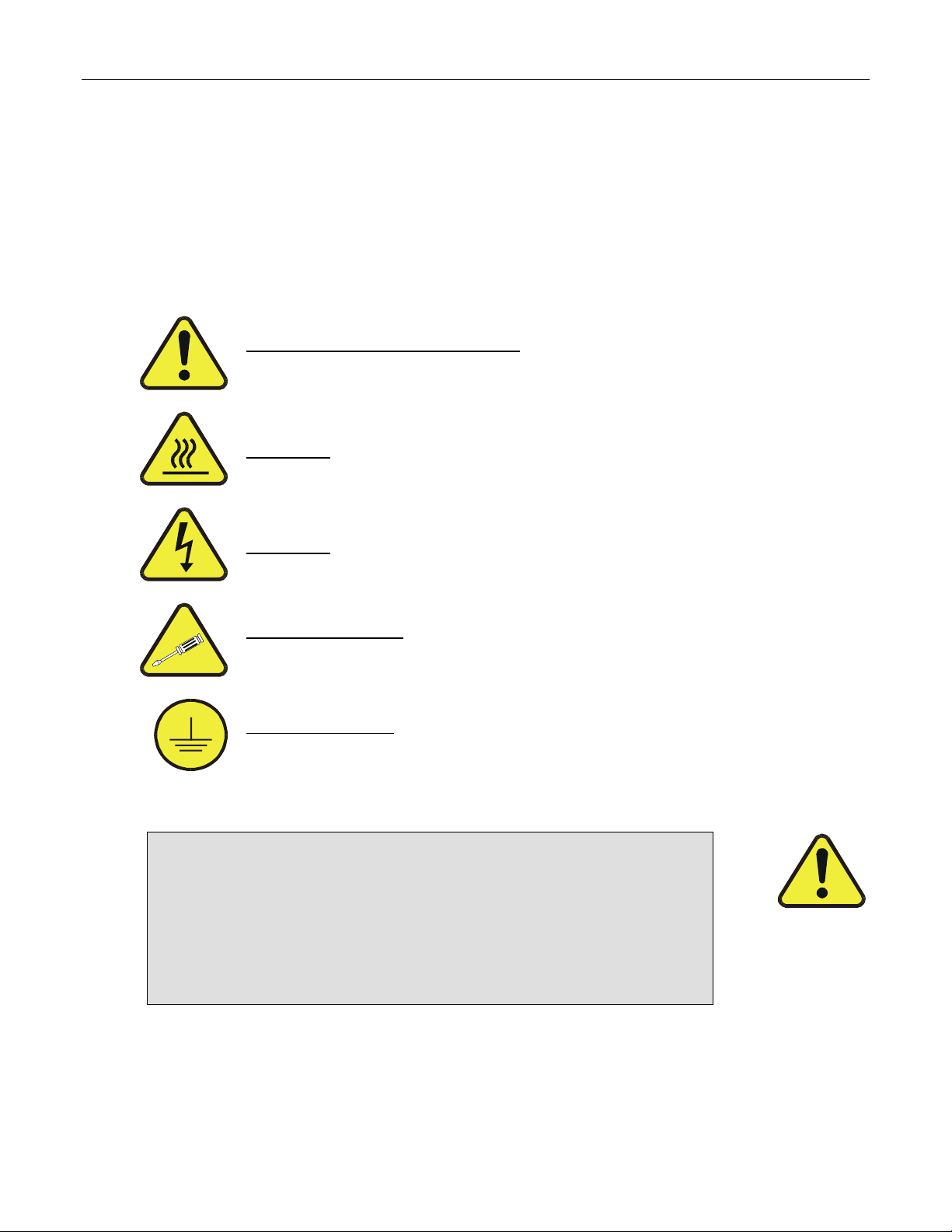
SAFETY MESSAGES
Your safety and the safety of others is very important. We have provided many important safety
messages in this manual. Please read these messages carefully.
A safety message alerts you to potential hazards that could hurt you or others. Each safety
message is associated with a safety alert symbol. These symbols are found in the manual and
inside the instrument. The definition of these symbols is described below:
GENERAL WARNING/CAUTION: Refer to the instructions for details on
the specific danger.
CAUTION: Hot Surface Warning
CAUTION: Electrical Shock Hazard
Technician Symbol: All operations marked with this symbol are to be
performed by qualified maintenance personnel only.
Electrical Ground: This symbol inside the instrument marks the central
safety grounding point for the instrument.
CAUTION
The analyzer should only be used for the purpose
and in the manner described in this manual.
If you use the analyzer in a manner other than that for which
it was intended, unpredictable behavior could ensue with
possible hazardous consequences.
1
Page 3

Teledyne API Model 201A NH3 Analyzer Instruction Manual, 04689, Rev. B1
TABLE OF CONTENTS
SAFETY MESSAGES .......................................................................................................1
TABLE OF CONTENTS...................................................................................................2
1 .0 M201A AMMONIA ANALYZER............................................................................6
1.1 PRINCIPLE OF OPERATION................................................................................................... 6
1.1.1 Special Considerations for Ammonia Measurement.................................................. 7
1.1.2 Sample Filtration........................................................................................................ 8
1.2 M201A ANALYZER SPECIFICATIONS..................................................................................... 9
2 .0 CALIBRATION PROCEDURE..............................................................................10
2.1 ZERO/SPAN CALIBRATION – BASIC INSTRUMENT.................................................................. 10
2.1.1 Zero/Span Calibration with Z/S Valves or ECO Option............................................ 13
2.1.2 TN/TNx Channel Calibration Quality........................................................................ 15
2.1.3 NH3 Calibration....................................................................................................... 16
2.1.4 Channel Calibration Quality..................................................................................... 17
3 .0 MAINTENANCE SCHEDULE...............................................................................18
3.1 M201A MAINTENANCE SCHEDULE ..................................................................................... 18
3.2 MAINTAINING THE M501NH CONVERTER............................................................................ 18
3.3 AUTOZERO FLOW CHECK.................................................................................................. 20
4 .0 M201A SPARE PARTS LIST..................................................................................28
2
Page 4

Teledyne API Model 201A NH3 Analyzer Instruction Manual, 04689, Rev. B1
LIST OF FIGURES
FIGURE 1 - M201A AMMONIA ANALYZER – BLOCK DIAGRAM ................................................................. 21
FIGURE 2 - M201A EXTERNAL PNEUMATIC CONNECTION DIAGRAM WITH ECO (EXTERNAL CALIBRATOR
OPTION)............................................................................................................................................. 22
FIGURE 3 - M201A PNEUMATIC DIAGRAM BASIC...................................................................................... 23
FIGURE 4 - M201A PNEUMATIC DIAGRAM Z/S OPTION............................................................................. 24
FIGURE 5 - M201A PNEUMATIC DIAGRAM EXTERNAL CALIBRATOR OPTION (ECO) ................................ 25
FIGURE 6 – M501NH CONVERTER CARTRIDGE ......................................................................................... 26
3
Page 5

Teledyne API Model 201A NH3 Analyzer Instruction Manual, 04689, Rev. B1
LIST OF TABLES
TABLE 2.1 - ZERO CALIBRATION PROCEDURE - ZERO GAS THROUGH THE SAMPLE PORT ......................... 11
TABLE 2.2 - ENTER THE EXPECTED SPAN GAS CONCENTRATIONS PROCEDURE......................................... 11
TABLE 2.3 - SPAN CALIBRATION PROCEDURE - SPAN GAS THRU SAMPLE PORT ........................................ 12
TABLE 2.4 - ZERO CALIBRATION PROCEDURE - ZERO GAS FROM REAR PANEL ZERO AIR INLET................. 13
TABLE 2.5 - ENTER THE EXPECTED SPAN GAS CONCENTRATIONS PROCEDURE......................................... 14
TABLE 2.6 - CALS - SPAN CAL PROCEDURE - GAS FROM REAR PANEL SPAN GAS INLET............................ 15
TABLE 3.1: PREVENTATIVE MAINTENANCE SCHEDULE............................................................................. 18
TABLE 3.2 – M501NH CONVERTER REBUILD PARTS LIST......................................................................... 19
4
Page 6

Teledyne API Model 201A NH3 Analyzer Instruction Manual, 04689, Rev. B1
5
Page 7

Teledyne API Model 201A NH3 Analyzer Instruction Manual, 04689, Rev. B1
1.0 M201A AMMONIA ANALYZER
This manual is to be used in conjunction with the M200A NOx Analyzer manual p/n
02246 supplied with this instrument.
The M201A Ammonia Analyzer consists of a modified M200A Nitrogen Oxides Analyzer
and M501NH Ammonia Converter:
A functional block diagram of the system is shown in Figure 1.
The instrument comes in three pneumatic configurations:
• The basic system is shown in Figure 3;
• The M201A with Z/S valves is shown in Figure 4;
• The M201A with External Calibrator Option (ECO) is shown in Figure 5.
Figure 2 can be used to connect the M201A system for installation. Please note that for a
M201A with either a Zero/Span or ECO option, you must connect the umbilical cord,
02255, between the analyzer and the converter assembly.
1.1 Principle of Operation
The Teledyne API Model 201A Analyzer measures ammonia by converting NH3 to nitric
oxide by the following reaction:
4NH
The resulting NO is then measured by the chemiluminescent reaction of NO with ozone.
Consult Section 4.1 in the M200A manual (provided with this instrument) for more
details on NO measurement.
A molybdenum converter is continuously in the pneumatic pathway, providing the TN
channel signal. The
converters are in series, creating the TNx signal.
The ammonia concentration is computed by the difference between the TNx and TN
channels, as shown in the following equation:
NH
See the pneumatic diagram in Figure 1.
+ 5O2 → 4NO + 6H2O
3
M501NH ammonia converter is periodically switched so both
→ TNx - TN
3
The actual formula for computation of ammonia concentration is more complicated than
the above equation, as it includes converter efficiencies, plus sample temperature and
pressure. The difficulty in ammonia measurement is that the molybdenum converter
6
Page 8

Teledyne API Model 201A NH3 Analyzer Instruction Manual, 04689, Rev. B1
converts some of the ammonia to NO, thus the TN channel data contains a small
ammonia signal. Secondly, the ammonia converter does not convert all of the ammonia
or ambient NO2 to NO. Finally, the high temperature in the ammonia converter causes
the oxygen and nitrogen in ambient air to react, creating a background of NOx which
needs to be factored into computing the result. Fortunately, all of the above
shortcomings have been overcome in the M201A by careful calibration, and calculation
of the result. .
Periodically, the AutoZero valve switches allowing the analyzer to read zero
background. The AutoZero readings are subtracted from all of the other readings. This
improves zero baseline stability.
As with many chemical reactions the conversion of ammonia in the presence of other
oxides of nitrogen is complicated.
In the molybdenum converter operating at 315
o
C, the following significant reactions are
taking place:
Mo + NO
+ Mo + O2 → MoO3 + NO <10% Eff
NH
3
→ MoO3 + NO ~100% Eff
2
Notice in the second reaction some of the ammonia is converted to NO by the
molybdenum metal.
The M501NH NH3 Converter operates at 825
o
C. At this high temperature, several
reactions occur:
NO → NO Efficiency = ~100 %
NOx → NO Efficiency = ~85%
NH3 → NO Efficiency = ~85%
N2 + O2 → NO Efficiency = <1%
As can be seen from the above reactions, the calculation of the ammonia concentration
and overall calibration of the instrument must be done carefully if accurate ammonia
concentrations are to be measured. The calibration procedure is covered in Section 2.
1.1.1 Special Considerations for Ammonia Measurement
Ammonia is a difficult gas to measure due to its chemical characteristics. Because of
its large dipole moment, the gas tends to adsorb on surfaces and diffuse into many
materials. The following precautions should be observed when designing an ammonia
sampling system and connecting the M201A analyzer to the system:
Materials:
Do NOT use TEFLON tubing or fittings in contact with NH3 sample or span gas.
7
Page 9

Teledyne API Model 201A NH3 Analyzer Instruction Manual, 04689, Rev. B1
Do NOT use copper tubing or fittings designed for household plumbing.
Use ONLY Chromatography grade (cleaned, passivated) stainless steel tubing
Use ONLY Glass tubing for sample inlet manifold.
These rules apply also to your calibrator’s internal plumbing. Verify that the calibrator
pneumatic pathway that contacts ammonia only uses stainless steel or glass tubing.
The M702SS calibrator supplied with the External Calibration Option is built with
stainless steel fittings and tubing for all internal plumbing wetted by NH3.
Typical ambient NH3 levels are < 15 ppb, unless there is some large source of
ammonia nearby, so the sampling and analysis system must be carefully designed and
well maintained.
1.1.2 Sample Filtration
The M201A does not come with a sample filter installed. Depending on the options
ordered, a sample filter may be separately packaged with the instrument. If the filter is
installed, the instrument response time is significantly increased, due to its large surface
area. Also, the condition of the filter (particulate loading and type) can adversely affect
the response time.
For minimum response time operation, the instrument should be supplied with clean
sample gas at ambient pressure.
If the sample filter is not included, the only additional filter in the M201A pneumatic
pathway is a ¼” dia stainless steel sintered filter used to protect the flow control orifice
from plugging. This filter will plug rapidly if the sample gas is not filtered before entering
the analyzer. Some means of filtering the sample gas, such as an external stainless
steel filter should be added upstream of the analyzer.
8
Page 10

Teledyne API Model 201A NH3 Analyzer Instruction Manual, 04689, Rev. B1
1.2 M201A Analyzer Specifications
Ranges 0-50 to 0-2000 ppb in 1 ppb increments
Range Modes Single, Independent, AutoRange
Noise at Zero
Noise at Span
Lower Detectable Limit 1 ppb RMS
Zero Drift
Span Drift < 1.0% FS Range / 7 days
Lag Time 40 sec
Rise Time 90% 120 sec
Fall Time 90% 120 sec
Sample Flow Rate 1000 cc/min
Linearity 2% of full scale
Precision 1.0% of reading
Temp Range 10-30oC
Dimensions HxWxD 7” x 17” x 23.6” (18cm x 43cm x 61cm)
Weight, Analyzer 43 lbs (20 kg)
Weight, Converter 24 lbs (11 kg)
Weight, Pump 16 lbs (7 kg)
Power, Analyzer 100V ~50/60 Hz, 120V ~60 Hz, 220V ~50Hz, 240V ~50 Hz,
Power, Analyzer
Power, Pump 110V ~60 Hz, 220V ~50 Hz, 240V ~50 Hz, 295 watts
Power, Pump CEMark5230 V ~50 Hz, 2.5 A peak
Environmental Installation Category Pollution Degree 2, Over-voltage
Analog Output 0-100, 0-1, 0-5, 0-10VDC bi-polar, 4-20mA isolated
Analog Resolution 1 part in 2048
Status Option 12 Status Outputs
Measurement Units ppb, ug/m3
1
1
3
0.5 ppb RMS
< 1.0% of reading above 50 ppb
2 ppb / 24 hours
125 watts
5
230V ~50 Hz, 125 watts
Category II
1. As defined by USEPA
2. Defined as twice the zero noise level
3. At constant temperature and voltage
4. Bi-polar
5. Electrical rating for CE Mark Compliance
9
Page 11

Teledyne API Model 201A NH3 Analyzer Instruction Manual, 04689, Rev. B1
2.0 CALIBRATION PROCEDURE
Calibration of the M201A is done by first calibrating the TN and TNx channels with NO
span gas diluted with zero air. In the second phase of calibration, ammonia span gas is
introduced to measure the overall system efficiency for NH3 conversion. Unlike NOx
analysis, the NH3 converter efficiency must be measured because it is considerably
lower than 100% and may change as the converter ages.
If the instrument is configured as a basic model, all zero/span gasses are introduced
through the sample port. If the Zero/Span valves option or the ECO option is ordered,
the zero/span gas is introduced through the zero/span valves. There are several ways
of automating the calibration or span check process, they are covered in Section 7 of
the M200A manual. After reviewing the procedure described below, it should be simple
to adapt the procedures in Section 7 to the M201A, if necessary.
2.1 Zero/Span Calibration – Basic Instrument
Since the zero gas concentration is defined as 0 ppb, it is not necessary to enter the
expected zero value.
10
Page 12

Teledyne API Model 201A NH3 Analyzer Instruction Manual, 04689, Rev. B1
Table 2.1 - Zero Calibration Procedure - Zero Gas Through the Sample Port
Step No.
Action Comment
1. Press
CAL
The M201A enters the calibrate mode from
sample mode. Input zero gas through the
sample port.
2. Wait 20
Wait for reading to stabilize at zero value.
min
3. Press
ZERO
If you change your mind after pressing ZERO,
you can still press EXIT here without zeroing
the instrument.
4. Press
ENTR
5. Press
EXIT
Pressing ENTR actually changes the
calculation equations.
M201A returns to sampling. Immediately after
calibration, data is not added to the DAS
averages.
Table 2.2 - Enter the Expected Span Gas Concentrations Procedure
Step No.
Action Comment
1. Press
This key sequence causes the M201A to
prompt for the expected TNX concentration.
CAL-CONC-TNX
Enter the TNX span concentration value by
pressing the key under each digit until the
expected value is set. This menu can also be
entered from CALS or CALZ.
2. Press ENTR ENTR stores the expected TNX span value.
3.
Press
CAL-CONC-TN
Now enter the expected TN span concentration
as in step one.
4. Press ENTR Pressing ENTR stores the TN span value and
returns the prompt to the CONC menu.
5.
Press EXIT Returns instrument to SAMPLE mode.
11
Page 13

Teledyne API Model 201A NH3 Analyzer Instruction Manual, 04689, Rev. B1
Table 2.3 - Span Calibration Procedure - Span Gas thru Sample Port
Step No.
Action Comment
1. Press CAL The M201A enters the calibrate mode. Input NO span
gas through the sample port.
2. Press
CAL-CONV-SET
Set the converter efficiency parameter to 1.0000, then
press ENTR-EXIT.
2. Wait 20 min Wait for reading to stabilize at span value.
3. Press SPAN If you change your mind after pressing SPAN, you can
still press EXIT here without spanning the instrument.
4. Press ENTR Pressing ENTR actually changes the calculation
equations and causes the instrument to read the TN
and TNx span concentrations.
5. Press EXIT M201A returns to sampling. Immediately after
calibration, data is not added to the DAS averages.
12
Page 14

Teledyne API Model 201A NH3 Analyzer Instruction Manual, 04689, Rev. B1
2.1.1 Zero/Span Calibration with Z/S Valves or ECO Option
The zero gas enters through the zero gas inlet port on the rear panel. Make sure that
the umbilical cord that makes the control connections between the analyzer and the
converter is connected (see Figure 2 below). The zero gas valve can be activated by a
variety of methods discussed in Section 7 of the M200A manual. The example below
will use the front panel keyboard to activate the valves.
Table 2.4 - Zero Calibration Procedure - Zero Gas from rear panel zero air inlet
Step No.
1. Press
2. Wait 20
3. Press
4. Press
5. Press
Action Comment
CALZ
min
ZERO
ENTR
EXIT
The M201A enters the calibrate mode from
sample mode. The zero gas is supplied
through the zero air inlet port on the rear panel.
Wait for reading to stabilize at zero. If the
instrument has recently been exposed to high
levels of NH3, you may need to wait up to 2
hours for the instrument to return to zero.
If you change your mind after pressing ZERO,
you can still press EXIT here without zeroing
the instrument.
Pressing ENTR actually changes the
calculation equations.
M201A returns to sampling. This switches the
ZS valves so that sample gas is coming in the
sample port on the rear of the instrument.
Immediately after calibration, data is not added
to the DAS averages.
Since the zero gas concentration is defined as 0 ppb, it is not necessary to enter the
expected zero value.
The expected value of the span gas is entered into the instrument by the following
procedure.
13
Page 15

Teledyne API Model 201A NH3 Analyzer Instruction Manual, 04689, Rev. B1
Table 2.5 - Enter the Expected Span Gas Concentrations Procedure
Step No.
Action Comment
1. Press
CALCONCTNX
2. Press
ENTR
3. Press
CALCONC-TN
4. Press
ENTR
5. Press
EXIT
This key sequence causes the M201A to
prompt for the expected TNX concentration.
Enter the TNX span concentration value by
pressing the key under each digit until the
expected value is set. This menu can also be
entered from CALS or CALZ.
ENTR stores the expected TNX span value.
Now enter the expected TN span concentration
as in step one.
Pressing ENTR stores the TN span value and
returns the prompt to the CONC menu.
Returns instrument to SAMPLE mode.
14
Page 16

Teledyne API Model 201A NH3 Analyzer Instruction Manual, 04689, Rev. B1
Table 2.6 - CALS - Span Cal Procedure - Gas from rear panel span gas inlet
Step No.
1. Press
2. Press
CAL-CONV-SET
2. Wait 20
3. Press
4. Press
5. Press EXIT M201A returns to sampling. Immediately after
Action Comment
The M201A enters the calibrate mode. The
CALS
Set the converter efficiency parameter to 1.0000, then
press ENTR-EXIT.
min
SPAN
ENTR
Z/S valves are activated to route span gas into
the analyzer.
Wait for the reading to stabilize at span value.
If you change your mind after pressing SPAN,
you can still press EXIT here without spanning
the instrument.
Pressing ENTR actually changes the
calculation equations and causes the
instrument to read the TN and TNx span
concentrations.
calibration, data is not added to the DAS
averages.
2.1.2 TN/TNx Channel Calibration Quality
After the TN and TNx channel calibration it is important to check the slopes and offsets
to make sure they fall within the acceptable range. The tolerances are different than a
typical NOx analyzer primarily because of the performance of the M501NH ammonia
converter.
Slopes can vary from 2.0 to 0.7, and should be within 20% of each other with the TNx
slope typically smaller than the TN slope.
Offsets should be zero ±250 mV and be within 100mV of each other.
If the slope and offsets are within specifications, proceed on the ammonia channel
calibration.
15
Page 17

Teledyne API Model 201A NH3 Analyzer Instruction Manual, 04689, Rev. B1
2.1.3 NH3 Calibration
Since the system efficiency is less than 100%, it is necessary to determine a conversion
efficiency factor for ammonia and enter it into the system.
1. Set the converter efficiency to 1.0000 by:
Press CAL-CONC-CONV-SET on the keyboard
Press the keys under the numbers until 1.0000 appears.
Press EXIT to return to the sample mode.
2. Introduce ammonia span gas of known concentration into the instrument. Allow time for
instrument stabilization. The final readings will be less than the concentration calculated
from flows. For example with 400 ppb NH3 span gas:
TN = 40 ppb
TNx = 380 ppb
The 40 ppb TN reading is due to the fact that the moly converts a small amount of the
NH3 gas to NO. The 380 ppb TNx reading is due to ammonia conversion plus some
conversion of nitrogen and oxygen in the dilution air.
3. Continuing with the example above, the instrument will report a NH3 concentration value of
340 ppb. Divide the reported NH3 concentration by the concentration computed from flow
data.
NH3 converter eff. = [NH3
M201A
] / [NH3
FLOWS
]
From the above example :
M201A NH3 reading = 340 ppb
NH3 conc from flows = 400 ppb
340 / 400 = 0.85 NH3 converter system efficiency
4. This value now is entered into the instrument.
Press CAL-CONC-CONV-SET
Press the buttons under the numbers until the desired value is entered, in this case
0.8500, then press ENTR.
Press EXIT to return to SAMPLE mode.
16
Page 18

Teledyne API Model 201A NH3 Analyzer Instruction Manual, 04689, Rev. B1
The instrument is now fully calibrated.
2.1.4 Channel Calibration Quality
After the ammonia channel is calibrated via the converter efficiency parameter, it is
important to check the calibration by sampling the NH3 calibration gas and confirming
that the instrument responds with the correct concentration. In the above example the
M201A should report 400 ppb NH3 concentration when measuring the 400 ppb NH3
span gas used.
17
Page 19

Teledyne API Model 201A NH3 Analyzer Instruction Manual, 04689, Rev. B1
3.0 MAINTENANCE SCHEDULE
3.1 M201A Maintenance Schedule
The maintenance requirements of the M201A are essentially like a standard M200A
NOx analyzer. Please refer to Table 8-1 in the M200A Operator Manual for the M200A
maintenance schedule.
In Table 3.1 below, there are the extra maintenance items required by the M201A.
Table 3.1: Preventative Maintenance Schedule
Item Maintenance Interval Reference Section
M501NH3 Converter Check every 6 months Section 3.2
Reaction Cell Clean quarterly as
necessary
AutoZero flow check Quarterly as needed Section 3.3
3.2 Maintaining the M501NH Converter
The M501NH Converter is operated at very high temperature. The center tube in the
converter slowly oxidizes and requires replacement. The most obvious indicator of
failure is no ammonia conversion, despite the converter being at temperature. This is
caused by the oxidized tube breaking off in the converter.
The following procedure describes how to disassemble and replace converter parts.
The various parts in the converter become delicate and brittle after prolonged exposure
to high temperatures. It is therefore a good idea to have a complete set of replacement
parts on hand before starting, as listed in Table 3.1.
Sect 9.3.8, Fig 8-3 in
the M200A Manual
18
Page 20

Teledyne API Model 201A NH3 Analyzer Instruction Manual, 04689, Rev. B1
Table 3.2 – M501NH Converter Rebuild Parts List
Part No. Description
KIT000191 Converter Rebuild Kit
KIT000139 Ceramic Bushings
HE0000007 Ceramic Heater 220W 60 VAC
Procedure:
1. Turn off power to the converter and allow to cool. IT IS VERY IMPORTANT THAT
THE CONVERTER BE COOL BEFORE ATTEMPTING ANY DISASSEMBLY OR
REPAIRS.
CAUTION VERY HOT
Will cause severe burns – disassembly while hot will
damage other converter components. Allow sufficient
time to cool.
2. Remove the chassis cover of the M501NH, remove the aluminum cover over the
oven, remove the two U-shaped hold down clamps.
3. Disconnect the 1 stainless steel and 2 PTFE tubes from the converter cartridge.
4. Loosen the nut holding the cartridge assembly in the U-shaped angle bracket
mounted on the chassis floor.
5. Gently lift and tilt the converter assembly out of the U-shaped bracket and slide the
assembly out of the oven.
6. Loosen the ¼” SS tube fitting nearest the hold-down bracket, this fitting holds the
central tube in the converter. Replace the tube that is part of KIT000191
7. Re-assemble the converter by doing the above steps in reverse order.
19
Page 21

Teledyne API Model 201A NH3 Analyzer Instruction Manual, 04689, Rev. B1
3.3 AutoZero Flow Check
Since the M201A is an ammonia analyzer, the flow through the AutoZero orifice is
especially important. Check the AutoZero flow as follows:
1. This procedure should be performed with the sample pump running.
2. Fold down the rear panel on the M201A chassis. Locate the vacuum manifold at the
center rear of the chassis. Locate the 1/8” tube fitting 2
label of “0.010”, indicating the flow orifice installed.
3. Remove the fitting and attach a calibrated flowmeter capable of measuring in the
range of 500 cc/min. The flowmeter should indicate a flow of 500 cc/min ±10%.
4. If the flow is outside this range (most likely lower, due to plugging):
1. Turn off the sample pump and instrument.
2. Remove the 1/8” pipe-to-tube fitting and remove the ¼” sintered filter (p/n
FL0001). This filter is meant to protect the orifice, it will usually become plugged and
need replacement rather than the orifice. Replace the filter, then re-assemble the
manifold. Re-start the sample pump and re-check the flow.
nd
from the left. It will have a
20
Page 22

Teledyne API Model 201A NH3 Analyzer Instruction Manual, 04689, Rev. B1
Figure 1 - M201A Ammonia Analyzer – Block Diagram
21
Page 23

Teledyne API Model 201A NH3 Analyzer Instruction Manual, 04689, Rev. B1
POWER
UMBILICAL
EXHAUST
OUT
NO SPAN GAS
SAMPLE
IN
50 PSIG MAX
INLET PRESSURE
NH3 SPAN GAS
CYL 1
CYL 2
IN
IN
TNTN
OUTOUT
TNX
OUT
ZERO AIR IN
CAL GAS OUT
SS TUBING
ZERO
SPAN
GAS
FROM
ZERO
AIR
MODULE
SS TUBING
AIR
SS TUBING
SS TUBING
VENT
TO VACCUM PUMP
TO
CONV
FROM
CONV
UMBILICAL
02522 UMBILICAL CORD
Figure 2 - M201A External Pneumatic Connection Diagram with ECO (External Calibrator Option)
22
Page 24

Teledyne API Model 201A NH3 Analyzer Instruction Manual, 04689, Rev. B1
Figure 3 - M201A Pneumatic Diagram Basic
23
Page 25

Teledyne API Model 201A NH3 Analyzer Instruction Manual, 04689, Rev. B1
Figure 4 - M201A Pneumatic Diagram Z/S Option
24
Page 26

Teledyne API Model 201A NH3 Analyzer Instruction Manual, 04689, Rev. B1
Figure 5 - M201A Pneumatic Diagram External Calibrator Option (ECO)
25
Page 27

Teledyne API Model 201A NH3 Analyzer Instruction Manual, 04689, Rev. B1
Figure 6 – M501NH Converter Cartridge
26
Page 28

Teledyne API Model 201A NH3 Analyzer Instruction Manual, 04689, Rev. B1
27
Page 29

Teledyne API Model 201A NH3 Analyzer Instruction Manual, 04689, Rev. B1
4.0 M201A SPARE PARTS LIST
000940400 Orifice, 4 mil, 80 cc, Rx Cell
000940600 Orifice, 10 mil, 500 cc, Rx Cell
002270100 Gasket (Rx Cell) Qty. 12
002730000 Window 665 NM
002761020 CPU Board (201A AMX))
003290000 Thermistor Assembly
004020200 Flow/Pressure Sensor Board
005140300 V/F Board
007040000 Keyboard
007280000 NEW Display
010680100 Heater, MOLY Converter
010860000 Status/Temperature Board
011310000 Drier Assembly Complete with Flow Control
011930000 PMT, NOx
011980000 Assembly, MOLY Thermocouple (Type J)
012360000 Fan, Power Supply Module
013140000 Fan, PMT Cooler
013570000 Thermistor Assembly (Cooler)
013600000 Operators Manual for M200A
014020300 M200A 37 mm 1 um Filter Expendables Kit
014020400 M200A 47 mm 1 um Filter Expendables Kit
014040000 M200A Level 1 Spare Parts Kit (for 10 units)
014040100 M200A Spares Kit for 1 Unit
014080100 Assembly, High Voltage Power Supply
014610000 Cooler Assembly
28
Page 30

Teledyne API Model 201A NH3 Analyzer Instruction Manual, 04689, Rev. B1
M201A Spare Parts List (cont.)
016810200 O3 Generator Assembly for M200A/200AH Low Output
017230000 Dryer Material, Drierite
018720000 Welded Moly Conv. Assy, w/ O3 Scrubber, w/ valves
021070000 PMT Pre-amplifier Board Assembly
022300000 DC Power Supply Board
024710000 Tubing: 6’, 1/8” CLR
024720000 Tubing: 6’, 1/8” BLK
024730000 Tubing: 6’, 1/4” BLK
024750000 Tubing: 6’, 1/4” TYGON
046890000 M201A Manual Addendum
046570100 Catalytic Converter Insert
CB0000001 FUSE O3, 1A
CP0000014 Fuji Temperature Controller
DR0000002 PMT Desiccant Baggies
FL0000001 Sintered Filter
FL0000003 Filter, DFU
FM0000004 Flow Meter, 0-1000 cc
HE0000007 Ceramic Heater 220W 60 VAC
HE0000017 Heater, Reaction Cell, 12W
HE0000019 Heater, MOLY Converter
HW0000020 Spring, Flow Control
HW0000036 TFE Thread Tape (48 FT)
HW0000150 Clamp, Hose, Nylon, 1/4”
KIT000019 Replacement Cooler Assembly, M100A/M200A
KIT000021 Replacement PWR SW BD, 'A', M100A/200A
KIT000036 Retrofit, O3 Killer
KIT000041 Retrofit, Moly Valves, M200A
KIT000051 Rebuild Kit, RX Cell Ambient, M200/A/251/252
KIT000058 Leak Checker with Gauge
KIT000059 Leak Checker without Gauge
KIT000067 Retrofit, M200A Rcell Rebuild Kit
KIT000103 Replacement, Welded Moly Cart, Type J Tc, Heater
KIT000110 Repl, Welded Moly Type J Tc w/o valves, w/o O3 killer, in can
29
Page 31

Teledyne API Model 201A NH3 Analyzer Instruction Manual, 04689, Rev. B1
M201A Spare Parts List (cont.)
KIT000129 Welded Moly, Cartridge only
KIT000191 Rebuild, NH3 INNER TUBE & CATALYST
OR0000001 O-Ring, Flow Control
OR0000002 O-Ring, Bearing, Cell
OR0000010 O-Ring, S, O3 Generator
OR0000012 O-Ring, Permeation Oven-Units with IZS
OR0000014 O-Ring, Permeation Oven
OR0000021 O-Ring, Scrubber
OR0000025 O-Ring, Zero Air Scrubber
OR0000034 O-Ring, Input/Output Mirror/Detector
OR0000042 O-Ring, Sensor Assembly
OR0000044 O-Ring, Reaction Cell
OR0000045 O-Ring, Sample Filter
PS0000010 15V Switching Power Supply
PU0000005 Pump 1150V/60Hz
PU0000006 Pump 220V/50Hz
PU0000011 607 Pump Rebuild Kit
RL0000003 Solid State Relay, 12 Vdc
RL0000007 3 AMP Opto Relay
RL0000008 Solid State Relay, 12 VDC
RL0000015 Solid State Relay, 115 Vac
SW0000006 Overheat SW, Cell/Oven
SW0000008 Pressure Sensor
VA0000007 Solenoid Valve, Stainless Steel, 12V
VA0000024 Manifold Valve, 3-Way, Vent
30
 Loading...