

Page 1
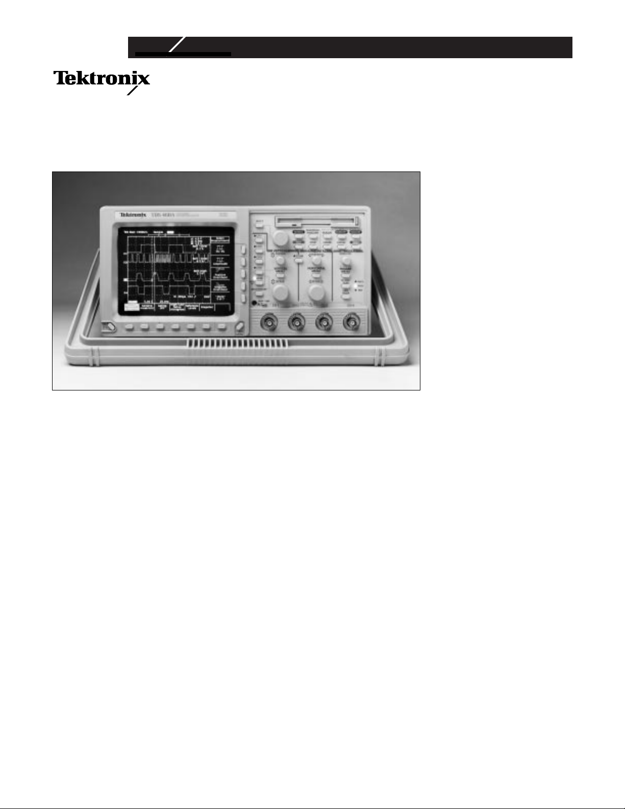
The TDS 460A 400 MHz, four channel, Personal Lab Scope.
TDS 400A Personal Lab
Oscilloscopes
For professionals who
demand high precision and
fidelity from their measurements, the TDS 400A Personal Lab Scopes combine
excellent performance and
broad feature set, all at
affordable prices. A choice of
2 and 4 channel models ranging from 200 MHz to 400
MHz with a 100MS/s sample
rate on all channels makes
the TDS 400A Series a worthy fit for a variety of
demanding applications.
The highly featured, portable,
and easy to use TDS420A,
430A and 460A personal lab
scopes are ideal for simple to
complex applications,
including electro-mechanical
research and analysis, power
electronics/power supply
design, bio-physical research
and analysis, digital and
analog design. With its standard video trigger capability,
the scopes are ideal instruments for measuring video
signals including NTSC, PAL
and SECAM.
The TDS 400A Series uses the
renowned TDS Graphical
User Interface which offers
intuitive icon-based menus
along with help text, making
scope operation extremely
simple. Knobs and buttons
allow easy selection of commonly used scope functions.
The standard floppy disk
drive makes the saving of
screen images or data to a disk
simple. The disk can then be
inserted into your PC for
importing to desktop publishing or spreadsheet programs.
Copyright © 1998 Tektronix, Inc. All rights reserved.
TDS 430A/TDS 420A/TDS 460A
Be Confident You’re Seeing Actual
Signals with up to 400 MHz
Bandwidth and ±1.5% Accuracy
Capture Transient Events to the Full
Scope Bandwidth with its 100 MS/s
Sample Rate
2 and 4 Channels
Record Lengths to 120K (option XL),
30K Standard
Floppy Disk Storage
Speed up your Circuit Analysis with
25 built-in Automatic Measurements
and optional extended Waveform
Math/FFT
Roll Mode Allows You to See
Acquired Data Points Without
Waiting for the Acquisition of the
Complete Waveform
Use the Video Trigger Mode to See
NTSC, PAL, SECAM Signals or your
Own Custom Video Signals
Capture those glitches with the 10 ns
Peak Detect Mode
Differential Measurements
ADA400A Analog Differential
Amplifier (10 µV/div Sensitivity)
P5200/P5205/P5210 High Voltage
Differential Probes (up to 5600 V) for
Floating Measurements
Applications
Biophysical/Biomedical Research
Electrophysical and
Electromechanical System Design
Audio System Measurement and
Analysis
Manufacturing Test and Quality
Control
Power Supply and Power-related
Design
Product Service and Maintenance
TDS 430A/TDS 460A/TDS 420A
Personal Lab Oscilloscopes
Page 2
SIGNAL AQUISITION SYSTEM
Bandwidth – 200 MHz (TDS 420A),
400 MHz (TDS 430A, TDS 460A).
Channels – 4 (2 on TDS 430A).
Sample Rate – 100 MS/s on all channels.
Sensitivity – 1 mV to 10 V/div
(with calibrated fine adjust).
Position Range – ±5 Divisions.
Offset Range – ±1 V from 1 to 99.5 ;
±10 V from 100 mV to 995 ; ±100 V from
1 to 10 V/div.
DC Gain Accuracy – ±1.5%.
Vertical Resolution – 8-Bits (256 levels
over 10.24 vertical divisions).
Analog Bandwidth Selections – 20 MHz,
100 MHz, and full.
Input Coupling – AC, DC or GND.
Input Impedance Selections – 1 MΩ in
parallel with 15 pF, or 50 Ω (AC and DC
coupling).
Maximum Input Voltage – 300 V CAT II
±400 Vpeak. Derate at 20 dB/decade above
1 MHz. 1 MΩ or GND coupled.
Channel Isolation – >100:1 at 100 MHz for
any two channels.
AC Coupled Low Frequency Limit – ≤10 Hz
when AC 1 MΩ coupled. ≤200 kHz when AC
50 Ω coupled.
ACQUISITION MODES
Peak Detect – High frequency and random
glitch capture. Captures glitches of 10 ns
using acquisition hardware at all real-time
sampling rates.
Sample – Sample data only.
Envelope – Max/min values acquired over
one or more acquisitions, selectable from
2 to 2000, infinite.
Average – Waveform averages selectable
from 2 to 10,000.
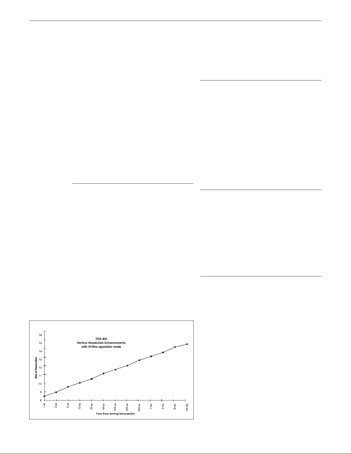
Hi-Res – Vertical resolution improvement
and noise reduction on low-frequency signals, e.g. 12-Bits at 10 ms/div and slower.
Enhanced vertical resolution (>12-Bits) for
noise reduction, on low frequency signals.
Make precise low-level signal measurements (up to 5 µV) with differential amplifier
(ADA400A).
TIME BASE SYSTEM
Time Bases – Main, Delayed.
Time/Division Range – 1 ns to 20 s/div.
Time Base Accuracy – 0.015% over any
interval ≥1 ms.
Record Length (real time and equivalent
time) – Sample points per channel: 500 to
30,000. Opt. XL offers 120,000 points.
Pre-Trigger Position – Selectable from
0 to 100% of record.
TRIGGERING SYSTEM
Triggers – Main, Delayed.
Main Trigger Modes – Auto, Normal, Single
Sequence.
Delayed Trigger – Delayed by time or
events.
Time Delay Range – 0 ns to 20 s.
Events Delay Range – 2 to 10,000,000
events.
External Rear Input – >1.5 KΩ; Max input
voltage is ±6 V (DC + AC peak).
Video Trigger Types – NTSC, PAL, SECAM,
and Custom; TV Field, field 2 or both,
Any line within a field.
Line Rates –10 kHz to 64 kHz, interlaced,
non-interlaced, composite.
Video Trigger Sensitivity –
0.6 divisions of composite SYNC will
achieve a stable display.
DISPLAY
Waveform Style – Dots or vectors.
Infinite and variable persistence from
250 ms to 10 s.
Gray Scaling – With variable persistence
selected, waveform points gradually
decay through 16 levels of intensity,
providing “z-axis” information about rapidly
changing waveforms.
Update Rate – 200 ea. 500 point waveforms per sec with infinite persistence
mode selected.
Graticules – Full, grid, cross hair, frame.
Format – YT and XY.
VGA Out – Drives VGA display monitors.
ZOOM
The zoom feature allows waveforms to be
expanded, compressed and positioned in
both vertical and horizontal axes. Allows
precise comparison and study of fine waveform detail without affecting ongoing acquisitions. When used with Hi-Res or Average
acquisition modes, Zoom provides an effective vertical dynamic range of 1000 divisions or 100 screens.
Characteristics
page 2
Theoretically achievable resolution with TDS 400A Hi-Res Mode.
Page 3

POWER REQUIREMENTS
Line Voltage Range – 90 to 250 V RMS.
Line Frequency – 48 to 63 Hz.
Power Consumption – 240 W max.
ENVIRONMENTAL SAFETY
Temperature – Operating: 0°C to +50°C.
Nonoperating: –40°C to +75°C.
Humidity – Operating and nonoperating: Up
to 95% relative humidity at or below +40°C;
to 75% relative humidity from +41°C to
+50°C.
Altitude – Operating: 15,000 ft., nonoperating: 40,000 ft.
Electromagnetic Compatibility – Meets
MIL-STD-461C, CE-03, Part 4, Curve # 1,
RE-02, Part 7; meets VDE 0871, Category B,
FCC rules and regulations, Part 15, Subpart
J, Class A.
Safety – Listed UL 3111-1, certified to
CAN/CSA – C22.2 No. 1010.1.
PHYSICAL CHARACTERISTICS
Dimensions mm in.
Height 164 6.4
w/acc. pouch 177 7.5
Width 362 14.25
Depth w/front cover installed 491 19.25
Depth w/handle extended 576 22.2
Weight kg lbs.
Net approximately 9.1 22.5
Shipping approximately 12.5 32
*1Waveforms can be stored to file in MathCAD and Spreadsheet
(Excel, Lotus 1-2-3) formats for analysis.
page 3
MEASUREMENT SYSTEM
Automatic waveform measurements –
Period Frequency
High Low
+ Width - Width
Maximum Minimum
Rise Fall
Peak to Peak Amplitude
+ Duty cycle - Duty cycle
+ Overshoot - Overshoot
Propagation delay Burst Width
Mean Cycle Mean
RMS Cycle RMS
Area Cycle Area
Phase -
Continuous update of up to four measurements on any combination of waveforms.
Thresholds – Settable in percentage or
voltage.
Gated – Any region of the record may be
isolated for measurement using vertical
bars.
Snapshot – Performs all measurements on
any one waveform showing results from
one instant in time.
Cursor Measurements – Absolute, Delta,
Volts, Time, Frequency.
Cursor Types – Horizontal bars (volts); Vertical bars (time); paired; operated independently or in tracking mode.
WAVEFORM PROCESSING
Waveform Functions – Interpolateselectable sin(x)/x or linear, Average,
Envelope.
Advanced Waveform Functions – FFT,
Integration, Differentiation (optional).
Arithmetic Operators – Add, Subtract,
Multiply, Invert.
Autosetup – Single button, automatic
setup on selected input signal for vertical,
horizontal and trigger systems.
Waveform Limit Testing – Compares
incoming waveform to a reference waveform’s upper and lower limits.
COMPUTER INTERFACE
GPIB (IEEE 488.2) Programmability – Full
talk/listen modes. Control of all modes, settings, and measurements.
HARDCOPY/DESKTOP PUBLISHING
Printer – HP ThinkJet, Epson, PostScript,
Interleaf, DeskJet, LaserJet, TIFF, PCX, BMP
(Microsoft Windows).
Plotter – HPGL.
Interface – GPIB standard.
Optional Hardcopy Interface – Centronics
Type and RS-232 (option XL).
Available Printer Pack – 4 in. thermal
printer and storage pouch (TDS4F5P).
STORAGE
Waveforms – 30,000 waveform points of
non-volatile storage, 120,000 points
optional (Option XL).
Floppy Drive – 3.5 in. 1.44 MB or 720 KB
DOS compatible (store waveforms, screen
data, and setups)*
1
Setups – 10 front-panel setups.
CRT
Type – 7 in. diagonal, magnetic
deflection. Horizontal raster-scan. P31
green phosphor.
Resolution – 640 horizontal by 480 vertical
displayed pixels.
Characteristics
(Cont.)
General
Characteristics
Page 4

8/98 HB/XBS 3GW-10375-4
Copyright © 1998, Tektronix, Inc. All rights reserved. Tektronix products are covered by U.S. and foreign patents, issued and pending. Information in this
publication supersedes that in all previously published material. Specification and price change privileges reserved. TEKTRONIX and TEK are registered
trademarks of Tektronix, Inc. All other trade names referenced are the service marks, trademarks, or registered trademarks of their respective companies.
For further information, contact Tektronix:
World Wide Web: http://www.tek.com; ASEAN Countries(65) 356-3900; Australia & New Zealand 61 (2) 888-7066; Austria, Eastern Europe, & Middle East +43 2236 8092 0; Belgium +32 (2) 715.89.70;
Brazil and South America 55 (11) 3741-8360; Canada 1 (800) 661-5625; Denmark +45 (44) 850 700;Finland +358 (9) 4783 400; France & North Africa +33 1 69 86 81 81; Germany + 49 (221) 94 77 400;
Hong Kong (852) 2585-6688; India (91) 80-2275577; Italy +39 (2) 25086 501;Japan (Sony/Tektronix Corporation) 81 (3) 3448-3111; Mexico, Central America, & Caribbean 52 (5) 666-6333;
The Netherlands +31 23 56 95555; Norway +47 22 07 07 00; People’s Republic of China 86 (10) 6235 1230; Republic of Korea 82 (2) 528-5299; South Africa (27 11)651-5222; Spain & Portugal +34 (1) 372 6000;
Sweden +46 (8) 629 6503; Switzerland +41 (41) 729 36 40; Taiwan 886 (2) 2722-9622; United Kingdom & Eire +44(0)1628 403400; USA 1 (800) 426-2200.
From other areas, contact: Tektronix, Inc. Export Sales, P.O. Box 500, M/S 50-255, Beaverton, Oregon 97077-0001, USA 1 (503) 627-6877.
TDS 430A
Two-Channel, 400 MHz Digitizing Oscilloscope.
TDS 420A
Four-Channel, 200 MHz Digitizing Oscilloscope.
TDS 460A
Four-Channel, 400 MHz Digitizing Oscilloscope.
All include: 1 Probe Per Channel (P6138A
10X Passive Probes); Video Trigger; Reference Manual (070-8035-03); User Manual
(070-8034-03); Performance Verification
Document (070-8721-02); U.S. Power Cord
(161-0230-01).
Instrument Options
Opt. XL – 120,000 Point Record Length;
RS-232 and Centronics Hardcopy Interfaces; Extended Waveform Math: FFT; Integration, Differentiation; Front Cover and
Accessories Pouch.
Opt. 1R – Rack Mount.
Opt. D1 – NIST, MIL-STD-45662A and ISO
9000 Calibration Data Report.
Opt. J2 – 2 year Post Warranty Repair.
Opt. J5 – 5 year Calibration Services. 5
years total.
Probes
Differential Probe –
400 MHz, 30 dB CMRR. Order P6246.
High Voltage Probes –
2.5 kV, 25 MHz, 2.75 pF/10M, 100X.
Order P5100.
20 kV, 75 MHz, 3pF/100M, 1000X, 3.1 m.
Order P6015A.
High Voltage Differential Probes –
Up to 1300 V, 25 MHz. Order P5200.
Up to 1300 V, 100 MHz. Order P5205.
Up to 5600 V, 50 MHz.order P5210
Passive Probe 1x – Order P6101B.
Passive Probe – 10X. Order P6138A.
FET Probe – Order P6205.
SMT Probe – Order P6562A.
TTL Logic Probe – Order P6408.
Optical Converters –
500nm to 950nm. Order P6701B.
1100 nm to 1700nm. Order P6703B.
DC/AC Current Probe System –
Order AM 503S, or TCP202 DC Coupled
Current Probe.
Recommended Accessories –
Analog Differential Amplifier –
10 µV sensitivity. Order ADA400A.
Current Measurement Capability –
Order AM 503S, and
appropriate probe.
Scope Cart – Order K212.
Rackmount Kit – Order 016-1166-00.
Soft-sided Carrying Case –
Order 016-1158-01.
Transit Case – Order 016-1157-00.
Optional Printer Pack – 4 in. thermal
printer and storage pouch. Order TDS4F5P.
Programmer’s Manual – Order 070-9876-00.
Service Manual – Order 070-9703-04.
Video Clamp – Order 013-0278-00.
Software Support
LabWindows®– Order S3FG910.
WSTR31 – WaveStar™waveform capture
and documentation software.
Cables
GPIB –
1 meter. Order 012-0991-01.
2 meters. Order 012-0991-00.
International power options
Opt. A1 – Universal Euro 220 V, 50 Hz.
Opt. A2 – UK 240 V, 50 Hz.
Opt. A3 – Australian 240 V, 50 Hz.
Opt. A4 – North American 240 V, 60 Hz.
Opt. A5 – Switzerland 220 V, 50 Hz.
International power options required on
instruments and selected accessories for
operation outside U.S. For operation
outside U.S., specify A1-A5 power options.
See General Customer Information Section
for description.
MEASUREMENT SERVICE OPTIONS
Opt. C3 – Three years of Calibration Services.
Opt. C5 – Five years of Calibration Services.
Opt. D3 – Test Data (requires Opt. C3).
Opt. D5 – Test Data (requires Opt. C5).
Opt. R5 – Repair warranty extended to cover
five years.
Ordering
Information
 Loading...