


4.
Tektronix
Instruction
TDS
Two
310,
TOS 320,
Channel
070-8568-02
Manual
&
Oscilloscopes
TDS
350

- . <
. . .--..e
-m.-.. .
TEK . INTER-OFFICE COMlvllJNlCATlON .-
.
TO
FWW
M3KC.T
Sohn Martin
Frank Gray, SO-PAT
GIDEP
permit request
In response to
Government
Tektronix
Tektronix, Inc.
of
such documents to any
in the
that all copies
copyright
in
pemieeion,a
Metrology
the
original, together with the Legend "Reproduded with
Industry
operator,
hereby grant6 such permission for distribution
of the
notice
Data
and ownership statement exactly a-& it appears
This permission has
Committee of
aeon%
1[
ded
to GIDEP to provide'the
94-540
the
request to grant permission to
Exchange
service and
Pro
GTDEP
ram
P
nstruction manuals,
user that is a full participant
Interchange Data Base
original
been
Tektronix
work include the
approved by
and
requested permission.
3:. ' t
(GPDEP) to reproduce
of
the
a
copy of this memo may
Juno 25, 1991
the
GIDEP provided
entire
Intellectual
g:&dy
Group Pat&t Coun&al

:9
I
S
Front Panel
TDS
300
Series
knobs
and buttonsonthe
control
tions
or buttons to
functions
that
you
typically
control
measurements.
oscilloscopes
are
menu
set
instrument
are
front
driven.
once
simpletouse.Toreduce
panel
(see
Figure
3-1),
Use
menustoaccess instrument
before
functions
making measurements.
that
you
most
many
often
the
clutter
instrument
Use
adjust
of
func
knobs
during
-
‘7,
riIk~o
r
Ii
___
nix_TDS3~COP~_~OOM~J
________
IWO
CIWIN~
NOLII
MIAWOO
~EFL_~)
-‘
~
o o
c~
11)0501,
o
OII~LA)ACOulRF
G~~5’
c
-
0000
VERTICAL FIORIZONTAL TRIGQEA
00011505
VERTICAL
—
MENU
P0511104
0
HORIZONTAL
MENU
0 0
soiis~~i~
LSVCL
0
TRIGGER
MENU
0
-o
oOH1
0~O
O
OMATH
0
0
0
~~OO
0
REF
2
-Q
-
Figure
3-1:
The
TDS
320
Oscilloscope
MENU
~
-wit
OH
1
OH
2
4,
Front
Panel
Ii
EXITHIG
TDS
310,
TDS
320,&TDS
350
Instruction
The
menus
operating
are
system,
choices.
This
section
illustrates
scriptionsofits
Manual
easytouse.
press
the
each
For
VERTICAL
control
useorfunction.
example,tomakeachangetothe
and
MENU
connector
buttontodisplay
and
contains
vertical
the
menu
briefde-
3-3

Front
Panel
Display
and
Controls
j
-s
Power
The
ON/STAY
button
instrument
/\
toggles
power.
~Tekt*ffon~x
The
accesstomain menu
page
user
TDS32O~U~Z~
Main
Menu
2-3
for
moreinformationonthe
interface.
-
buttons
provide
selections.
.!~.
See
J
U
1J
U
U
ci.
Mt~l1
The
accesstoside
page
user
The CLEAR
menus
from
Side
Menu
2-2
for
interface.
MENU
the
screen.
buttons provide
menu
more
button
selections.
informationenthe
clears
SI
See
a.
SI
all
3-4
F!
F!.:
.4
A—
Operation

Fro~j
Panel
Vertical
d~spfay
CH2,
light
when
Connectortochassis
Controls
The
Waveform
and
select
MATH,
nexttoa
REFI,
that
button
waveformIsselected.
$ele~t
buttons
wavEforms
and
RE~2).
illuminates
(CHI,
~
O CH
o
OH
1
2
OM,ATH
oREF
OREF
2
0B~
1
COMP
The
V&,’jj~~J
CofltfOlS
the
The
up
l~or
operations, see
The
vertical
selected
The
turnS
waveform.
the
presently
VERTICAL
the
vertical
more
i,~o
VOLrS/Qft(
scale
waveform.
WAVEFORM
off
the
presently
POSITION
vertical
position
selected
MENU
buttOn
operations
rmaf
ion
OtT
page3-7.
knob
controls
of
(he
presently
OFF
button
selected
knob
of
wao/Oform.
calls
menu.
vert/cal
the
Probe
See
110W
compensation
page
2-7
tO
compensate
for
instruOt,ons on
the
output.
probes.
TDS
310,
TDS 320,&TIDS
350
ln~truction
Manual

Front
Panel
Horizontal
Controls
—
HORIZONTAL
HORIZONTAL
MENU
SEC)IDIV
0-
The
HorizOntal
controls
waveforms.
The
up
For
operations
The
horizontal
waveforms.
the
HORIZONTAL
the
honzorotal
more
Informationonhori~c’nfal
SEC/DIV
POSITION
horIzontal
MENU
operations
see
page 3-20.
knob
scaleofthe
controls
knob
positionofall
button
calls
menu.
the
active
H
-—ii
Operation

Front
Panel
Trigger
The
Indicate
iri~gering
light
iFJ$frunJeflt
The
a
valid
READY
the
instrument
trigger
when
Controls
Trigger
Status
the
StatusOfthe
system.
illuminates
that
The
recognizesavalid
andiswaiting
when
trigger.
light
illuminates
can
eventtooccur.
Lights
ThIGD
the
accept
for
TRIGGER
C)
U
SET
LEVEL
TO
50%
TI~!G’D
READY
FORCE
T~GER
The
Trigger
the
trigger.
The
TRIGGER
up
the
page
on
triggering.
trigger
3-25
LEVEL
MENU
menu.
for
more
knob
controls
bUtton
calls
See
hlfornJatIOn
lIDS 310, TDS
The
SET
the
(rigger
between
signal.
320,&TOS
LEVEL
TO 50%
ievolatthe
the peaksofthe
350
Instruction
button
half-way
tngger
Manual
sets
point
The
FORCE
the
oscilloscopetostart
waveform
trigger
no
effectiftile acquisition
stopped.
TRIGGER
regardlessofwhet
event
occurs.
button
acquiring
This
forces
her
button
system
a
a
has
is

Front
Pa~eI
Miscellaneous
Controls
The
MEASURE
automated
See
page
on
autO~flated
The
UTILITY
menu.
See
informationonutilities.
The
AUTOSET
setsupthe
usable
displayofthe
For
more on
see
page
button
measurements
3-29
button
page
instrumenttoproduce
the
2-11.
callsupthe
menu.
for
more information
measurements.
callsupthe
3-45
far
more
button automatically
input
autoset
signals.
function,
utility
a
The
HARDCOPY
print
operations.
for
more
har~l
copies.
in?
ormstiOfl On
button
See
page
The
and
starts
3-41
making
RUN/STOP
stops
acquisition.
button
starts
The
General
many
the
cursors.
switches
cursor.
The
SAVEIRECALL.
callsupthe
See
page
On
5aving
The CURSOR
cur5or
Informationonmaking
measurements
The
DISPLAY
display
informatiOn
display.
side
control
3-43
menu.
menu.
Purpose
menu
functions,
the
TOGGLE
from
save/recall
for
and
recalling
button
See
with
button
See
on
controlling
SETUP
more information
page
cursors.
callsupthe
page
Knob
controls
including
button
cur5or
10
button
setup
menu.
setups.
callsup~he
3-33
for
3-39
for
the
SAVE/AECALL
SETUP
CURSOR
The
4COUIRE
acquisition
for
more
information
controlling
ACQUIRE
button
menu.
See
on
acquisition.
calls
page
tip
the
237
El
El
3-B
—
Operation

Display
The
(stopped,
acquisition
Map
Status
Readouts show
waiting
for
status
rateornumberofacquisitions).
(mode
trigger
trigger,
and
status
etc.)
and
sampling
Trigger
position
(T).
The
the
value
general
knob,
entered
purpose
with
When
knob
knob
the
is first
icon
general
assigned,
appears
purpose
the
here.
Trigger
Trigger
Channel
Run: 2OMS/s
level
indicator
point
indicator
Ground
Indicator
Shows
Sample
what
indicates
position
vertical
cursorsinthe
waveform
partofthe
record.
wave
of
bar
form
recordisdisplayed.
Trigger
Level:—1OmV
The
waveform
record
icon.
Cursor
measurement
readouts.
page
in
formationoncursors.
The
a
choiceofspecific
actions.
3-33
side
menu offers
See
for
more
The
Channel Readout
shows
the VOLTS/DIV
of
all
active
los
310,
TDS
channels.
320.&TDS
350
The
main menu offers
a
Choiceofmajor
actions.
Instruction
Manual
The
shows
M
indicates
D
indicates
Time
the
Base
time
base
(M)ain
(D)elayed
base.
Readout
setting.
time
base,
time
The
Trigger
shows
and
the
triggeredonthe
falling
waveform.
Wheninvideo
mode,
displays
trigger
Field2,or
Readout
the
trigger
level
and
instrument
edgeofthe
the
readout
source
feature
Lines).
source
whether
is
rising
trigger
and
(Field
or
1,

Front
Panel
Inputs
The
and
channel
CH2)
signals
BNC
inputs
accept
for
display. page
(CHI
electrical
The
EXT
external
3’26
on
external
TRIGinput
trigger
signals.
for
more
triggering.
accepts
See
information
Operation

Rear
Panel
~1d
F.
The
Option14Panel
instruments
three
Centronics parallel
interlace,
You
can
and
hardcopy
hardcopy
You
can use
interfacestooperate and
oscilloscope
see
the
Programmer
in
formation.
only)
communications
andaGPIB
use
GPIB
the
interlacestotransmit
data;
procedures.
the
TOS
310, 320,&350
information.
(Option
allows
port,
interface.
Centronics,
see
page
GPIB
and
fromaGPIB
Manual
for
14
access
interfaces:
an
RS-232
RS-232,
3-41
for
RS-232
program
controller;
more
The
to
voltagetopower
a
page
connectoroptions.
the
power
connector
1-3
foralist ofpower
accepts
the
instrument.
cord
line
See
and
The
fuse
page
drawer
8’9
See
procedures.
for
holds
fuse
replacement
the
line
fuse.
TDS
310, TDS 320,&TDS
350
Instruction
Manual

Menu
Maps
I
TRIGGER
MENU
P
C—
Lett-most
main
menu
button
Pop-up
Type
Edge
Main
Menu
Source
Coupling
Slope
Level
Mode
Holdotf
~
-~
Side
Menu
CH
CH
Ext
Ext(lO
AC
DC
AC
HF
LF
Reject
Noise
I
Rising
Falling
Level
SelloUt
SettoECL
Setto50%
Auto
Normal
Holdotf
Setto
SideMenu~
1
2
Line
Reject
Reject
Mm
-
TRIGGER
MENU
o
I
—
Left-most
button
main
menu
HORIZONTAL
MENU
~
Pop-up
Type
Video
Main
Menu
~
Time
I
Trigger
Main
-
Source
Trigger
Mode
Holdoft
Base
Position
Menu
,~,
On
~
}
I
I
I
~
Side
Menu
ii,
Cdl
0h2
Ext
Ext~1O
AC
Line
I
Field
Field
Lines
Auto
SettoMm
Normal
Holdofl
Side
Menu
II!
Main
Only
Intensified
Delayed
Only
Delayed
Runs
After
Main
Pretrig
er
Setto~O%
Setto5O%
Setto90%
I
1
2
I
I
Main Menu
VERTICAL
MENU Invert
C
Coupling
Bandwidth
Fine
Position
Offset Fine
DC
AC
GND
Invert
,,.,,_.,.,..j
Scale
‘“‘~••Lj
_________
Figure
I
Invert
Full
Bandwidth
Vertical
Set
toO Divs
Vertical Offset
Setto0
3-2:
Oft
On
Scare
Position
V
Primary
Functions
OMATH
o--I
o
REF
C
Or
o
REF 2
C
Menu
I
Map
Side
Menu
Ch1i-Ch2
P
I
Ch2-Chl
Ch
I-Ch
Ch1‘Oh
Side
Menu
CR1
CR2
MATH
RefY
I
Horizontal
2
2
I
I
Save
Position
to Ref
Lock
F
F
F
X
F
F
3-74
Operation
1•

SAVEIREOALL
SETUP
C
CuRSOR
C
Main
H
Menu~
Save
Current
Setup
Recall
Saved
Setup
Recall
Factory
Setup
Mwn
Menu
Function
Time
Units
Side
-Vff
—I
Menu
To
Setupi
To
Setup2
To
SetuplO
Recall
Setupl
Recall
Setup2
Recall
SetuplO
OK
Confirm
Side
Menu
H
bars
V
bars
Paired
1/seconds
Seconds
(Hz)
Main
Menu
Style
Intensity
C
—1
Readout
Graticule
Format
Main Menu
~
acouine
C
Mode
~
Stop
After
Side
Menu
Vectors
Dots
Vector
Accumulate
Dot
Accumulate
Overall
I
Text/G
rat
Waveform
Contrast
DisplayT@
Frame
Full
YT
XV
Side
Menu
Sample
Peak
AverageEnvelope
Run/Stop
Single Acquisition
Trigger
Detect
Bufton
Menu
Maps
Point
Only
Sequence
u~i~
C
Pop-up
Jr
Config
f/O
Diag
Cal
Main
JH
______~~~
Menu
Jr
Figure
3-3:
Secondary
Side
Menu
Jr
Centronics
GPIB
Landscape
Portrait
Hard
Copy
T/L
Address
Hardcopy
Off
Bus
Formats
RS-232C
Con
I/aural/on
OK
Confirm
MEASuRE
C
Functions
—
Menu
Side
Main
Menu
Automated
Measurements
Select
Remove
High-Low
Setup
Reference Gate
Levels
Gating
•—~~__~
~
Measurement
Measurement
AU
Measurement
Histogram
Max/mm
Set Levels
High
Mid Ref
Low
Map
Menu
Measurement
Measurements
Ref
withVBar
In
Ret
I
2
3
Cursors
4
TDS
310,
los
320,&TOS
350
Instruction
Manual
3-15

-
..
..
•.#•qa~
II
.—.~———~‘-.
..4...V...a...~.~
~
.I.~...._a......
~......_.aep.._..,_._~
..• ...p. I
.11
.....i,~i...,
1
,fl~.r.,..
Vertica’ Operations
There
are
four
oscilloscopes.
•
You
can
Change
systems
•
You
can
add, subtract,
tu
re
•
You
can
save
ries
To
access
the
vertical
showninFigure
The
VERTICAL
channel
ence
the
waveform (CH
waveformisselected,
mathorreference
Manipulating
basic
waystomanipulate
their
display
themtoand
System
parameters
and
multiply them
recall
features, press
waveforms with
them
from
Waveforms
-
wfth
the
with
reference waveform
the
VERTICAL
3-4.
NOTE
MENU
button
callsupthe
I orCH2)/s
the
selected.Ifa
VERTICAL
waveform menu.
vertical
MENU
TDS
Vertical
the
waveform
menu
mathorrefer
button
300
Series
and horizontal
math
tea
memo
MENU
button,
onlyifa
-
calls
up
-
-
I
I
I
I
I
11
3
Figure
3-5
shows
Figure
the
Vertical
oOH1
CI
OCH2
C
0
C,
OREF
C
OREF
C
3-4:
-~
_____VERTICAL
MATH
I
2
PROSE
COMP
—
5V41.
The
menu.
VERTICAL
~.
POSETiON
MENU
VOLTSIOiV
0
WAVEFORM
Off
C
VERTICAL
F
MENU
~1
—
Verticai
Button
Menu
TD5
310,
TOS
320,&TD5
350
Instruction
Manual
3-17

Manipulating
Waveforms
7
LC
C~CI~J
Figure
3-5: The
Vertical
Menu
-x
ci
I
0
U
E
Use
the
vertical
Select
side
invert
menu to turn
form flips” around
signal.
Input
menu to select
a
Invert
accordinglyToobtainastable
press
menu to
Coupling
Waveform
invert off
the
flips”
the
SET
LEVELTO50%.
DC,
-~-
and
zero
waveform,
perform these
—
Press
the main
AC, or
Press
on.
volt
the
When
ground
main
axis.
NOTE
butitdoes
trigger
tasks.
(GND)
menu
you
turn
Figure
after
menu
button
coupling.
3-6
not
button
invert
alter
Invert.
on, the
showsaninverted
the
trigger
inverting
Coupling.
Use
selected
level
a
waveform,
Use
the
wave
pulse
the
side
-
~!
3-lB
OperCtiOfl

—
Manipulating
Waveforms
r
10k
twIn:
Normal
Wave!
orm
200MS/s
RE’
—
Sample
0
inverted
Waveform
Select
side
Make
Scale
precise
—
RQI
I
1V
25011$
I
I
Type
I
Edge
Bandwidth
Source
Figure
—
C112
Press
Coupling
DC
3-6:
the main
menutoswitch between20MHz
Fine
V/div
Adjustments
to activate
adjustmentstothe
the
General Purpose
vertical scale
I
V512SOflS
Slope
Inverting
menu
and
—
Press
Knob.
setting.
012
Level
40111V
a
Waveform
button
full
bandwidth.
the main
Then
x
401,V
mode
Auto
Bandwidth.
menu
use
the
Hoidolt
5000$
Use
button Fine
knobtomake
U
U
the
105
310,
lOS
320,&TOS
350
Adjust
activate
positionoruse
Vertical
Adjust
the
side
as
waveform that
Instruction
Vertical
the
General
the
positionislimitedtoa
This
selection performs
knob.
Vertical
General
menu to
the
Manual
vertical
Purpose
set
the
POSITION
hasalargeDCbias.
Position
side
—
Purpose
menu to
Press
Knob.
set
range
the
same functionasthe
Offset—Press
Knob. Then
offset
toOV.Offset
knob,
butithasawider
the main
Then,
the
of±5
NOTE
the
main
use
the
menu
use
the
vertical
position
divisions.
menu
button
knobtoadjust
performs
the
range. Use
-
button
Position
knobtoadjust
toO
divisions.
vertical
POSiTION
Offset
to activate
offsetoruse
same
basic
oftsettoview
to
vertica~
the
function
a
3-19

Manipulating
Waveforms
Horizontal
To
access
Operations button,
horizontal
showninFigure
Teic
Run:
Figure
200MS/s
system
3-7: The
3-7.
Sample
features,
Figure
press
3-8
11OR~Z0NTAL~
P051110W
0
HORIZONTAL
MENU
c:::::~—--—----—-~
SEC/Div
0
HORIZONTAL
the
shows
Oela~’
HORIZONTAL
the
horizontal
Hoñzontal
MENU
Tüue-
Button
1.00
5~s
~nne~seI
MENU
menu.
Menu
p
U
ii
I
I
Use
~Po~o~nTTTh
L~I~II~
the
horizontal menu to
Figure 3-8: The
perform these
Ii
250115
Clii1—30
Horizontal
tasks.
OlnV
Menu
I
ritensilled
____
DeI~yed
OI,ly
____
Set
to
Mill
U
U
I
3-20
operation

Manipulating
Waveforms
e
Select
the
•
•
•
•
•
Adjust
Trigger
the Time
side
menu to
Press
Main
Press
Intensified to
oscilloscope
indicates
Use
the
al
Purpose
Press
Delayed Onlytoshow
Use
the
between
coarse
fine
increments
increments
Delayed
Base—Press
select
Onlytoshow
intensifiesaportionofthe
the
locationofthe
SEC/DIV
Knob
General
the
main
when Delayed
Runs
After
Press SETtoMm
Horizontal
Position.
Use
Trigger
trigger position,oruse
10%,
50%,or90%ofthe
the main
from
these
only
show
both
delayed
knobtochange
to change
its
only
Purpose
Knobtoadjust
and delayed
when
Main
OnlyorIntensified
Onlyisselected. The
Main
shows
to set
the
delay
Position—Press
the
General Purpose
side
menu
selectionstoset
waveform
options.
the
main
the main
time
the
position.
the
time
bases).
the
timetoits
record.
menu
button
time
base.
and
delayed
waveform;
base
with
lengthofthe
delayed
the
time
delay
You
delay
time.
minimum
the main
Knob
to
the
Time
time
this
intensified
respecttothe
zone
and
base.
time
(the
adjust
the
are
selected
side
menu
value.
menu
adjust
trigger
horizontal
position to
Base.
bases.
the
interval
delay
and
selection
button
Use
The
zone
main.
Gener
time
in
in
-
Displaying
Waveforms
Math
TDS
300
Series
forms or
form.Toactivate
Figure
subtract
3-9.
oscilloscopes
one
from
the
Math
the
math waveform,
oCHI
OCH2
0
OREF
(~2
Figure
can
add or multiply
other
and
~Iv
I
~
I
lcD
MATH
I
1
PROBE
COUP
3-9:
The
display
press
the
VERTICAL
a.
POSITION
VERTICAL
MENU
VOLTS/DIV
WAVEFORM
MATH
the
the
MATH
OFF
Button
two
channel
resultasa
button,
wave-
math
shown
wave-
in
TDS
310, TDS 320,&TDS
350
Instruction
Manual
3-21

1
Manipulating
Waveforms
Then
selectaformula
Chl,orCH1
toasine
waveonChannel
*
Ch2).
from
Figure
the
side
menu
(Chi+Ch2,
3-/0
showsasquare waveonChannel2added
1.
Chi—Ch2,
Ch2
—
I
Saving
and
Waveforms
Recalling
Figure 3-10:AMath
TDS
300
Series
Oscilloscopes
the
reference
forms).
to
the
other.
Reference
position and
There isnowaytohorizontally
To
save a
waveform buttons
waveformstostore
You
can
also shiftastored
waveforms
scale,
live
waveformtoa
(REF1or
respond
but
theydonot
reference
REF2)showninFigure
Waveform
have
two
reference waveforms.
live”
waveforms
waveform
just
like live
respondtohorizontal
expandareference
from
waveforms to
waveform, press
You
can use
(channel
one reference waveform
waveform.
and
math
changesinvertical
scale
adjustments.
one of
the
reference
3-11.
wave-
E
F
F
3-22
Operation

IL
‘~
1
COMP
svfl.
I
I
I
VERTICAL
~
POSITION
VERTICAL
MENU
C
-
VOLTSIDIV
WAVE;0AM
OFF
c
Waveform
Buttons
oCH1
•
I
-
Ref
Ref
2
—
Figure 3-11:
cJfl
OCH2
C
OMATH
OREF1
OIREF2
_—*KJ
PROSE
/“
The Reference
w
If
the selected
the
screen. A
side
menu
•
•
Press
lected
reference waveform already
side
menu
also
appears;
(see
Figure
Save
CH1toRef(x)tosave the channel1waveform to
reference waveform.
3-12).
holdsawaveform,itappears
select
one of
these
options
from
these-
on
the
•
-
•
•
Press
Save
CH2toRef(x)tosave
lected
reference waveform.
•
Press
Save
MATHtoRef(x)tosave
reference waveform.
•
Press
Save
Ref(y)toRef(x)
to the
selected
to
Ref2.)
•
Press
Horizontal
modes.InLock
waveformislockedtothe
selected
reference waveform.
reference waveformisindependently positionable.
to
save
Positiontotoggle
mode, the
horizontal
live
waveforms.InIndependent
the
channel2waveform
the
math
waveform to
the
unselected
(For
example,
between
positionofthe
the
Lock
to these-
the
selected
reference
Ref2toRef1or
and
selected
waveform
Independent
reference
mode,
the
Ref
1
NOTE
If
you
saveawaveform
contents
willbeoverwritten.
to
a
“full”
reference
waveform,
its
previous
R
TDS
310,
TOS
320,&TDS
350
Instruction
Manual
3-23

Manipulating
Waveforms
Tek
The reference
the power
waveform
waveform
stateorsetupofthe
from
simply
iLlU:
1
I~I
S/s
Sa
inple
Figure 3-12:AReference
waveforms
maintain
their
instrument.Toremoveaselected
the
display,
press
its
press
front
WAVEFORM
panel
HorizoI,Ial
contents
button
Posil
10,,:
4
Iie~
Save
CH
I
to
11012
Save
CH2
to
RefZ
Save
MATH
to
11e12
Save
Roll
to
11e12
Waveform Menu
indefinitely,
OFF.Torecallareference
(REF1or
REF
regardless
reference
2).
of
Operation

TDS
300
Series
andavideo
GER
MENU
oscilloscopes
trigger.Toaccess
button,
showninFigure
TRIGGER~
LEVEL
0
O
o
SET
LEVEL
TO
50%
have
trigger
TRieD
READY
FORCE
TAICOER
two
triggers:astandard
settings
and
3-13.
Trigger
Triggering
edge
trigger
features,
Menu
press
the
TRIG-
Edge
Triggering
This button
trigger
menu
two trigger
The
edge
can
access
Figure
3-14.Besure
Figure
callsupone of
Press
the
menus.
trigger
triggersonthe
edge
trigger
the
3-13:
The
two
leftmost
settings
leftmost
TRIGGER
menus:
main
the
menu
edge
risingorfalling
through
main
the
menu
MENU
Button
trigger
menu or
the
buttontoswitch between
edgeofthe
edge
trigger menu, shown
selection
input
indicates
signal.
Type
video
the
You
in
Edge.
lOS 310,
TI3S
320,&TDS
350
Instruction
Manual
3-25

Triggering
Figure 3-14:
Use
the
edge
trigger
Select
the
•
•
the
Trigger
side
menutoselect
Press
ChiorCh2toset the
Press
Ext
or
the
front
panel.
ten,
Note
that
nals,itcannot
•
PressACto
Select
the
•
•
•
Trigger
side
menutoselect
PressDCto selectDCcoupling.
PressACto
Press HF
rejection
This
gering
Rejecttoselect
removes
allows
system.
menu to perform
Source—Press
from
Ext(1Otoset
Ext/b
while
display
set
the
attenuates
the
them.
trigger
Coupling—Press
from
selectACcoupling.
the
high
only
the
low
High
frequency
30kHz.
The
these
options.
trigger
the
trigger
instrument
sourcetothe
the main
these
options.
high
frequency
frequency
frequency
reject
Edge
Trigger
these
tasks.
the
main
sourcetoone of
sourcetothe
the
external
can
triggeronexternal
oscilloscope
portionofthe
menu
menu
reject
Menu
input
button
mode.
button
the
input
EXT
TRIG
signalbya
line
Coupling.
High
triggering
componentstopassonto
mode
attenuates signals
.
Source.
channels.
input
factor
trigger
voltage
frequency
signal.
the
above
Use
On
of
sig
-
signal.
Use
trig
-
3-26
•
PressLFRejecttoselect
rejectionisthe
reject
mode
oppositeofhigh
attenuates
low
signals
frequency
reject
frequency
below80kHz.
mode. Low
rejection.
Low
frequenCY
frequency
Operation

I
1
•
Press
Noise
DC
low sensitivity,
Reject
to select
noise reject
butitrequires
mpde.
additional signal
Noise
rejection provides
amplitude
Triggering
for
stable
triggering.
selection
front
Change
top
going
Adjust
two
Trigger
side
slope.
Trigger
menu
menu to select
•
Use
the
General
performs
panel.)
•
Press
SettoTTLtoautomatically
ing
threshold.
•
Press
SettoECLtoautomatically
ing
threshold.
•
Press
Setto50%toset
source
the
signal.
SET
LEVELTO50%
Select Trigger
menu
to select either
In
normal
trigger
internal
trigger
signal
source.Inauto
triggerinthe
Slope—Press
buttonstoswitch
Level—Press
from
these
options.
Purpose
the
same
the
(Note
that
Mode—Press
AutoorNormal
mode,
the
oscilloscope
absenceofother
the main
between
the
main
menu
positive-going
menu
Knobtoadjust trigger
functionasthe
set
the
trigger
set
the
trigger
trigger
this
buttononthe
leveltothe
selection performs
front
the main
menu
mode.
waits
foravalid
trigger
mode, the
trigger
oscilloscope
events.
button Slope.
button Level.
level.
(Note
trigger
LEVEL
leveltothe
leveltothe
midpointofthe
the
same
panel.)
button Mode.
trigger
Use
the
and negative-
Use
the
side
that
this
knobonthe
TTL
switch-
ECL
switch-
trigger
function
Use
from
produces
the
the
as
side
an
TDS
310,
TOS
320,&TUS
350
Instruction
At
horizontal
mode
switchestoan
mode
the
envelope
and
the
display
Adjust
General
Holdoff—Press
Purpose
haveaholdoff
Mmtoquickly
Manual
scale
settingsoflOOms
untriggered
and
average acquisition
does
not
showatrigger
the
Knob.
Use
range of 500nsto
set the
holdoff
roll
main
the
knob
10 s.
to 500
per
display.
“T”onthe
menu
to
Press
ns.
division and
When
the
modes does
waveform.
button
adjust
the
Holdoff
holdoff;
side
slower,
displayisin
not work
to activate
the
TDS
menu
button
auto
trigger
“roll”
properly,
the
300
Series
Set
to
3-27

TDS
300
Series
youtoobtain
quantitative
measurements
Taking
oscilloscopes have
data
fromadisplayed
and
cursors.
Measurements
two
features
that
make them
easy
waveform: automated
for
Automated
Measurements
The Oscilloscope
waveform
ments,
(four
press
measurementsatany
the
5~Qc:)
The
MEASURE
can
perform21different automated
one
MEASURE
Figure 3-16:
button
button,
(AurosEr
activates
showninFigure
)
SAVEIRECALL
The
MEASURE
the
measure
time).Toaccess
Measure
UTILITY
SETUP
CIfi~SOR
Button
menu,
showninFigure
measurementsona
these
measure
3-16.
(
RUN/STOP)
DISPLAY
ACOUrRE
3-17.
-
TOS
310
TDS
320,
&
TDS
350
Instruction
Manual
3-29

Taking
Measurements
/-
L
Tfl
Run:2OMS/s Sample
7
/
I ~‘
/
~.ThI
SOOfllV
Select
Measrnlnt
for
RemoveICaRing
Nleasrmnt
Chi
It
SpIed
M
easLire
Cli
I
Allipi
2.06
dli
FER
lUSkflz
/•
Cli
~1M
1.
772111V
/
~
Chi
Fall
3.3S!~S
.1IOmV
I
V
4
PaIi*
A
Rise
Time
Fall
PoslIlve
OLILY
Negative
OLity
—more—
2
Time
Cycle
Cycle
Of
6
Li
Li
Li
H’
/1,
/
I
I.
~.,
,./
/ i,~
NI
25j.is
1K
igli—LowIRe
SelLip
NI
ill—Max
•\
•
Clii
ference
Levels
Use
Figure 3-17:
the
measure
The
Measure
menu to perform
ActivateaMeasurement—Use
ment
for
the
selected
1.
Press
the
main
2.Ifnecessary,
outof6)topage
surement
3.
Then
you
press
waveform
menu
button
press
the
lowermost side
through
wanttotake
oneofthe top
Select
the
available
appearsinthe
four
measurement.
The
measured
Figure
3-17.
values
For
appeartothe
definitionsofthe
available
~
Menu
and
Active Measurements
the following
this
proceduretoactivateameasure
Measrmnt
tasks.
for....
menu
button
measurements
c~J
(labeled
until
side menu.
side
menu
left
buttons
of
the
side menu,asshown
measurements,
to activateaparticular
see
NOTE
—more--
the
mea
in
Table
p1
-
x
-
3-1.
3-30
Measurements
only
remain
active
activate several measurements
WAVEFORM
OFF
button,
the
measurements
waveform.
while
the
forachannel
channelisactive.Ifyou
and
then
press
the
disappear
lust
—
like
the
Operation

Table
3-1:
Measurement
Definitipns
Taking
Measurements
Name
sir
siLF
JL
~r
—~
JLF
Period
Frequency
Positive
Negative
Rise
Fall
Width
Width
time
Time
Positive Duty
Cycle
Definition
Timing
peninthe
in
Timing
reciprocal of
measurement
waveform or
seconds
measurement
the
second.
Timing
distance
measurementofthe
(time)
between
pulse.
Timing
distance
measurementofthe
(time)
between
pulse.
Timing
waveform or
High
Timing
measurement. Time
gated
Ref
value
(default=90%)ofits
measurement. Time
waveform or gated
Low
Ref
value
(default=10%)ofits
Timing
ratioofthe
measurementofthe
positive
age.
Timeittakes for
gated
for
the
period.
Measured
MidRef
MidRef
regiontorise
regiontofall
pulse
widthtothe
region.
first
cycleinthe
first
pulseinthe
(default
first
pulseinthe
(default
taken
fromaLow
taken
fromaHigh
first
cycleinthe
the
The
in Hertz
for
the
final
for
the
final
signal
first
complete
signal
cycletohap
reciprocaloffrequency Measured
waveform
(Hz)
waveform
50%)
waveform
50%)
amplitude
leading
Ref
where1Hz
amplitude
value
o(gated
=
or gated
pointsofa
or gated
pointsofa
edgeofthe
first
(default=10%)toa
region.
I
cycle
per
region.
positive
region.
negative
pulseinthe
The
The
value.
falling
edgeofthe
Ref
value
first
pulseinthe
(default=90%)toa
value.
waveformorgated region.
period
expressedasa
The
percent
-
The
-
I
I
JLF
JUF(
J
Negative
Cycle
Burst
Positive
Overshoot
Negative
Overshoot
High
-
Duty
Width
Timing
ratioofthe
measurementofthe
negative
age.
NegativeDutycyc/e
Timing
form
Voltage
Voltage
The
needed
meaEurement.
or gated
region.
measurement
measurement. Measured
value
usedas100%
(asinfall
waveformorgated
PositiveoutyCycle=Posftiv!
first
cycleinthe
pulse
widthtothe signal
Negative
=
The
durationofa
over
the
entire
Positiveovershoot
burst.
waveformorgated
Max—High
=
over
the
NegativeOvershoot=LowniyiIn
time
whenever
and
rise
High
time measurements).
Widthx100%
Penod
waveformorgated region.
period
Period
Measured
-
. x
Amplitude
entire
Amplitude
Ref,
Mid
region.
expressedasa
Width
x
700%
over
the
region.
100%
waveformorgated
x
100%
Ref,
and
Low
Ref
Measured
-- -
over
The
percent
entire
wave-
region.
values are
the
entire
-
I
TDS
310,
105
320,&TOg
350
Instruction
Manual
3~31

Taking
Measurements
Name
Low
needed
IL]
Lu
~1
F
i:
:~.~::
:.:
.
Table 3-1:
Measurement
Definition
The
value
Maximum
Minimum
PeaktoPeak
Amplitude
usedas0%
asinfall
waveform or gated
Voltage
peak
Voltage
peak
measurement.
voltage.
Measured
measurement.
voltage.
Measured
Voltage measurement. The
minimum amplitudeinthe
Voltage measurement. The
time
region.
whenever
and
The
over
The
over
entire waveform or gated
Mean Voltage measurement. The
region.
Cycle Mean
Voltage
measurement.
form,orthe
first
cycleinthe
The
Definitions
rise
time
maximum
the
minimum
the
absolute difference
(Cont.)
High
Ref,
Mid
measurements.
Ref,
amplitude.
entire waveform or gated
amplitude.
entire waveform or gated
between
entire waveformorgated
high
value
less
the
low value
region.
Amplitude=High—Low
arithmetic
arithmetic
gated
mean
mean
region.
over
over
and
Low
Ref
the
values are
over
the
most
Measured
Typically
region.
Typically
the
most
negative
region.
the
maximum
region.
measured
the
entire waveform or gated
the
first cycle in
over
the
entire
S
positive
and
the
wave-
t----
...--.~.
Cycle
RMS
RMS
Voltage
in
measurement.
the
waveform,orthe
The
first
Voltage measurement. The
waveform or gated
region.
RemoveaMeasurement—Press
Measrmnt.
mentsoruse
Use
Gating
Use
the
the top
By
lowest side
measurementsonthe
onlyaportionofthe
of that
1.
2.Ifnecessary,
3.
portion.
Press
the main
outof6) to
surement
Then
press
Use
press
page through
you
wanttotake
one of
measurement.
true
Root
Mean
Square
cycleinthe
true
Root
gated
Mean
region.
Square
the main
four
side
menu buttons to remove specific
menu
buttontoremove
default,
waveform,
this
menu
TDS
300
Series
entire waveform
you
record.Ifyou
can
use
procedureto“gate”asignal.
button
the
Select
Measrmnt
lowermost side
the
available
appearsinthe
the
top
four
side
menu buttons to activateaparticular
voltage
voltage
menu
over
over
button
all
measurements.
oscilloscopes
wantameasurement
gatingtomark
for....
menu
button
(labeled
measurements
side
menu.
the
first cycle
the
entire
Remove
measure
take automated
the
boundaries
—more—
until
the
mea
-
-
of
X
3-32
4.
5.
6.
Press
Press
Use
your
the main
the
side
the
General
gate.
menu
menu
Purpose
button
button
Gating.
Gate
with
Knobtoset
V~Bar
one
cursortothe
Cursors,
left
edge
Operation
of

7.
Press
8.
Use
the
of
the
portionofthe
9.
Press
Gate
the
vertical
describedinthe
TOGGLE.
General
gate.
All
automated
waveform thatiswithin
Gate
Off
Off
deactivates
cursors.
Purpose
to turn
Deactivate
next
Knobtoset
measurements now take
gating
the
section.
off.
NOTE
gating
the
the
the
function,
cursors
Taking
other
cursortothe
data
gate.
butitdoes not
from
the
cursor
Measurements
right
only
from
the
deactivate
menu
as
edge
Switch
Setuptochange
low
•
I
Set
to
these
the
•
I
•
High-Low
levels
of waveforms.
Press
Histogramtoset
to
find
the
ignoring
and
Press
and
Reference
set
the
levels
side
Press
between
Press
level. Use
level.
spikes.
pulse
Mm—Maxtoset
highest amplitude
high,
for
menu to select
Set Levelsinto
voltsand
High
The defaults
Setup—Press
the
way
the
Use
highest
waveforms.
middle, and
rise
the
densityofpoints
This
method
Levels—~Press
time,
fall
from
percent.
Ret,
Mid
Ref,orLow
General
are
the main
measurement
the
side
menu to select
the
levels
statistically
works well
the
leve!stothe lowest
(most
positive)
the main
low
reference
time,
width, and
these
options.
toggle
90%,
the unitsofthe
Purpose
50%,
Ref
Knobtoafter
and
menu
button
system
above
for
samples.
menu
levels.
to selectaparticular reference
10%,
determines
The
and below
measuring
amplitude (most
button
The
overshoot
reference levels.
the
respectively.
High—Low
the
from
these
options.
oscilloscope
the
midpoint,
square
Reference Levels
oscilloscope
measurements.
selected
waves
uses
Switch
reference
high
and
attempts
negative)
Use
I
Taking
Measurements
Cursors
TDS
7~O,
TD.S
320,&TOS
with
350
‘lou can
system.Totake measurements
1.
Instruction
also take
Press
SOP
Manual
the
front
button
quantitative
panel
button
callsupthe
measurementsofa
with
cursors,
CURSOR,
cursor
menu,
showninFigure 3-18.
showninrigure
follow
waveform
this
procedure.
2-19.
with
the
The
cursor
CUR-
3.33

——
~Th,!,:... ~. ~ ~ ~ ~-,-•:,a~~ ~ ~
Taking
Measurements
Cursor
_________
UTILITY
SAVEIRECAI.L
SETUP
DISPLAY
I:
RUN/STOP)
ACQUIRE
Figure
3-18:
The
CURSOR
Button
E
Figure
2.Ifyou
3.Ifthe
4.
wanttotakeatime
press
the main
switch
menu
Use
between
main
button.
the
side menu
menu
menu
the
two.
selection
to select
SelectHBarstotakeavoltage
time
measurement,
time
measurements.
or select
3-19:
The
Cursor
measurementinHertz
button
Time
Units
Functionisnot
the
typeofmeasurement
measurement,
Pairedtotake
Menu
instead of seconds,
and
use
the
side
highlighted,
you
selectVBarstotake
simultaneous
menu to
press
its
wanttotake.
voltage and
main
a
I
Operation
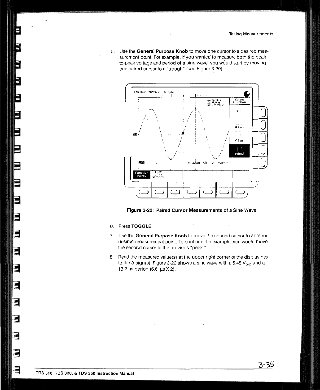
5.
Use
surement
to-peak
one
the
paired
I
General
point.
voltage
Cursortoa
Purpose
For
example,ifyou
and
periodofa
trough”
Knobtomove
wanted to
sine
wave,
(see
Figure
one
cursortoa
measure
you
3-20).
would
Taking
Measurements
desired
both
the
startbymoving
mea
peak-
U
U
0
-
6.
7.
8.
Press
Use
desired
the
Read
to
13.2
I
Figure
the
second
the~sign(s).
3-20:
TOGGLE.
General
measurement
cursortothe
the
measured
i~s
period
II If I~
Paired
Purpose
Figure
(6.6IsX
Cursor
point.Tocontinue
previous
value(s)atthe
3-20
2).
Measurementsofa
Knobtomove
“peak.”
showsasine
upper
the
the
example,
right
wave
second
II II
li~J
Sine
cursor
you
cornerofthe
witha5.48
Wave
to another
would
move
display
and
next
a
lOS
310, TDS 320,&TDS
350
Instruction
3-35
Manual

Warranted
Characteristics
Warranted
limits
characteristics.
The
tics
ture
20
and
minutes,
electrical
apply
Performance
Conditions
Table
4-1: Warranted
Name
Accuracy,DCVoltage
Average
Accuracy,
I
Average
Acquisition Mode
DC
Gain,
Acquisition
Measurement,
Sample
Modes
or
characteristics
that
are
warranted. This subsection
In
these
tab/es,
the
Performance
type
under
the
characteristics
when the oscilloscope has
between
+55°C(unless
+20’Cand
andisoperating atanambient
Characteristics—Signal
Description
Measurement
Averageof~16waveforms
Delta
volts
between any two
eragesof16waveforms
quired
and
±2%
under
ambient conditions
are
those
warranted
Tests,
column
+30°C,has
otherwise
Type
the
same
describedinterms of
lists
NOTE
characteristics
startingonpage
Name.
toundinthese
been
noted).
Acquisition
av-
ac-
setup
6-11,
tablesofwarranted
adjusted
hadawarm-up
temperature
DC
±
(2.0%
Net
Accuracy
±(20%
+
0.3
quantifiable
only
warranted
that
are
checked
appearinboldface
at an ambient
periodofat
between
System
Accuracy
xI(reading
Offset)!±Offset
-I-
0.1
div)
x reading~
my)
performance
in
characteris
tempera
least
_1OU
—
+
0.15 div
-
C
-
Pulse
Response,
Envelope
Mode
Peak
Detect
and
Sec/Div
55/div—25
10
lOps/div—5
10
Setting
ps/div—10
ps/div—.2.5
ps/div
ns/div
ns/div
ns/div
(TDS
(TDS
(TDS
310)
320)
350)
Minimum
iOns
The
.02><sec/div
Pulse Width
greaterof10nsor
setting
I
IDS
310,
TLJS
320,
&
TOS
350
Instruction
Manual
4-3

Warranted
Characteristics
Table
4-1~
Warranted
Characteristics
Signal
Acquisition
System
(Cant.)
Name
Accuracy,
Analog
Cross
Input
Input
Lower
tNet
Offset
Accuracy
2Th~ACCoupled
Offset
Bandwidth,
Talk
(Channel Isolation)
Impedance,
Voltage,
Frequency
Offset
~s
the
accuracy
DC
Coupled
DC-Coupled
Maximum
Limit,
AC Coupled2
—
(Position~VoIts/Div).
of this
vOIta~e
Lower
Frequency
level.
Limits
Net
ofl~et
are
reducedbya
Description
Volts/[3iv
2
mV/div—99.5
100
1
V/div—10
DC—50
DC—100
DC—200
1
00:1at50
1
MC~
±400V(DC
Setting
mV/div—995
V/div
M1~z
MHz (lOS
MHz
Ml-lz
±1%inparallel
-i-
13VpeakACat
~10Hz
is
the
voit~ge
factor ot10when
mV/div
mV/div
(TDS
310)
(TDS
with
peak
AC):
3MHZ
level~tthe
320)
350);
DC—180
equal
Volts/Div
with20pF
derateat20
and
above
centerofthe
1DX,
passive
Offset
Accuracy
±(0.4%><Net
~i--3my +
ting)
±
(0.4%xNet
+ 30mV+
ting)
±
(0.4%
+ 300
mV
ting)
MHz
settingsoneach
±2.0
pF
dB/decade
A-ID
converter
probes
are
Offset
0.1
d~V
Oftse1~
0.1
dlv~Vldiv
>< j
Net
Offset1
+
0.1
divxV/div
for2mV/div
above
dynamic
used.
1
I
>(
V/div
I
channel
100
rgnge.
set
kHz
Offset
set
set
-
-
-
to
~IH
Name
Accuracy,
and
Accuracy,
ments1’
1~or
lr~put
be
acquiredata
2TboWI(wavotorm
and
Equivalent
Delay
2
signals
Long
Time
~J~Ita
5
voIts/dIvi~ion
rime
Table 4-2:
Warranted
Description
Term Sample
Time
Measure-
Rate
For
bandwidth
For
16averages andabandwidth
divisionsinamplitude andaslew
setting5mV/division.
interval)Isthe
or
Interpolated
time
between
Wa.,etorm
the
Rates
Characteristics—Time
±100
ppm over
any1ms
single-Shot acquisitions
limit
settingofFULL:
±(1
WI+100
ppmxReading~+0.6
repetitive acquisitions
±(1WI+
rate of 22.0
samplesinthe
iii
Table
100
ppm
divisions/nsatthe
waveform
4.11onpage
interval
using
using
x Reading~
record.
Also,
442.
Base System
sample
average
limit
delta
see
acquisition
acquisition
setting
-4-
0.4ns)
time
measurement
the
tootnotes
ns)
of
FULL;
tar
mode and
mode with
points.
Signal
Sample
Rate Range
a
must
1
I
Sp~CifiC~ti0fl5

S
Table 4-3:
Warranted
Characteristics—Triggering
System
Warranted
Characteristics
Name
Accuracy,
Sensitivity,
Coupled
Trigger
Level,DCCoupled
Edge-Type
Trigger,
DC
Description
Trigger
CH1
Source
orCH2
Sensitivity
±(3%of
+
Offset
External
External/b
Trigger
Source Sensitivity
±
(6%ofSetting
±(6%ofSetting~
CH1orCH2 TDS
to20MHz,
50
TDS
to50MHz,
100
TDS
to
50MHz, increasingto1
200
External
TDS
20Mhz,
50MHz
TDS
50
100
TDS
50
200
0.2
Setting
dlv><volts/div
—
NetOffset
setting
Accuracy)
I
+
20
200
310;
035
division
increasingto1
MHz
320:
035
dflvision
increasingto1
MHz
350:
0.35
division
MHz
310:50myfromDCto
increasingto150myat
320:50mVfromDCto
MHz,
increasingto150myat
MHz
350:50my
MHz,
increasingto150
fromDCto
MHz
my)
my)
from
from
from
div
div
div
my
1~
±
DC
at
DC
at
DC
at
at
El
Input
Impedance,
Maximum
External
~Net
Offset=Offset—(PositionxVolts/Div). Net
Accuracyisthe
Input
Trigger
External
Voltage,
accuracyofthis
Trigger
voltagelevel.
External/b
1
MO
±2%inparallel with
±400V(DC±peak
iSV
peak ACat3
Offsetisthe
vouage
levelatthe centerofthe
AC);
MHz
TDS
310:
20
MHz,
50
MHz
TDS
320:
MHz,
increasing
MHz
TDS
350:
MHz,
increasingto1.5
200
MHz
20 pF±2pF
derateat20db/decade
and
above
A-D
converter
500
mVfrom
increasing
to
DCto
1.5
500mVfromDCto
to 1.5
Vat
500mVfrom
DCto50
Vat
above
dynamic
100
range.
kHz
Vat
50
100
to
OffseI
TUS
310, TDS 320,SIDS
350
Instruction
Manual
4-5

Warranted Characteristics
Name
Source
Power
Voltage and
Consumption
Name
Atmospherics
Dynamics
Emissions
1 Meetsorexceeds the
Susceptibility2
Frequency
Table 4-5:
Warranted
Table 4-4:
Power
Requirements
Description
90
to 132
132to250
65
Watts (120
VAC~MS,
VACRMS,
continuous
Continuous
VA)
Characteristics—Environmental,
Description
Temperature:
—10°Cto
—51°
Relative
to
95%,
+55°C,operating;
Cto
+71°C,
humidity:
at or
below
non-operating
+40°C;to
Altitude:
To
15,000ff
to
40,000ft(12190
Random
0.31
2.46
vibration:
g
g
(4570
RMS
from5to 500
AMS
from5to
m),
operating;
m),
non-operating
500
non-operating
requirementsofthe
EN
50081—1
EN
55022
EN
55022
EN
60555—2
VFG
0243
FCC
Rules
TDS
310
0.4
division
TOS
350:
increaseinp-p
placement,ors±0.6
500
MHz.
The
instruments
European
radiated emissions
ClassBconducted
power
harmonics
and
Regulations,47CFR,
and
TDS
320:
increaseinp-p
~±0.2
division
noise
below
division
are
subjectedtothe
Community
±0.2
noise.
waveform
200
increaseinp-p
standards:
EN
50082—1
IEC
IEC
IEC
European
801—~radiated
801—4
801—SAC
fast
transients
surge
Community
susceptibility
range,
Safety,
range,
75%,
for
47Hz
for
47Hz
and
Reliability
+41°Cto
through
Hz,10minutes each
Hz,10minutes each
following
Requirements
emissions
Part
15,
SubpartB,Class
division
waveform
displacement,
displacement,or0.4
MHz.
~±0.3
division
noise
EMI
specifiedinthe
Requirements
440
Hz
through63Hz
+55°
C
axis,
operating:
axis,
standards:
division
waveform
from
200
MHz
following
A
or
dis
E
E
F~
-
to
‘To
maintair,
(braid
listedinTable
~Susceptibility
triggersource
and
emission
foil)
4~5
requirements
cable.
The
1-’l
on
page
test
run
seE10Line.
with
cable
I-s.
both
the
Acquisition
when
shield
channel
connectingtothe
must
have
low
inputs
terminated
Mode
settoPeak
I/O
Interface
Impedance
with
Detect,
of this
oscilloscope,
connectionstoboth
grounding
and
the
caps,
time
both
base
use
only~high-quality, double-shielded
connector
channels setto2
5etto25
housings.
ps/Div.
Acceptable
mV/Div.DCCoupling,
cable5
Speciti~tl0fl5
SrO
the

S
S
a
Typical
performance.
Table 4-6:
Name
Accuracy,DCGain,
Acquisition
Accuracy,DCVoltage Measurement,
Sample
Frequency
Bandwidth
Mode
Acquisition
Limit,
Limited
Envelope
Mode
Upper,20MHz
Typical
Typical
characteristics
Typical
Characteristics—Signal
Description
±3%
for
sec/div
~2%for
±2%
±2%
Measurement
Any Sample
Delta Volts
pies
up
20
sec/div
for
sec/div
tor
sec/div
2
acquired
and
ambient conditions
MHz
are
characteristics
settings
settings
settings
settings
Type
between
any two sam-
under
describedinterms of
the
Characteristics
typicaloraverage
are
not
warranted.
Acquisition
from5Sec/Divto25
from10ps/div to10nsldiv
from10Ms/divto5
from
10
same
set-
System
psec!div;
na/div
Ms/divto25
DC
±(2.0%
±
ns/div
Accuracy
Offset’
+ 013
(2.0%><readingI+
+
1.2 my)
x(Jreading—Net
I) +
div+0.6
(TDS
310):
(TDS 320);
(TDS
350)
Offset
Accuracy
mV)
0.28 div
Step
Response
Common Mode
(CMRR)
1N~
Offset Offset—(PositionxVolts/OW).
Accuracyisthe
2The
samples mustbeacquired
3The
values
crossingofthe
amplitude.
I
4Referenceisa
TDS
350.
Settling
Rejection
accuracyofthis
given
are
the
step,
and
9-div
p-p
Error
Ratio
voltage
under
maximum
the
value
sine
wave
Volts/Div
2
mV/div —99.5 mV/div
100
995
1
V/div—10
100:1at60Hz,
Coupling
Net
Offsetisthe
level.
the
same
setup
absolute difference between
one
second
after
input
sampledat200
Setting
mV/div
mV/div
settingsoneach
and ambient
the
mid-level
MS/s
Step
Amplitude
2
V
—
V/div
reducingto20:1at50MHz,
voltage
levelatthe centerofthe
conditions.
the
valueatthe
crossingofthe
for
the
TDS
520V
~200
channel.
endofa
step, expressed
310,
500
MS/s for
V
A-D
specified
the
Settling
lOOns
1.0
51.5
2.5
with
equal Volts/Div
converter
time
Interval after
as
a
percentageofthe
TDS
320,
Error
dynamic
andIGS/s
(%)3
2Oms
Sill
50.2
50.2
and
range. Oftset
the
mid-level
step
for
the
105 310, TDS
320,&TOS
350
instruction
Manual
I

Typical
Characteristics
Table
4-7: Typical
Characteristics—Triggering
System
Name
Error,
Trigger
Sensitivity,
Lowest
eration
Frequency
of
Sensitivity,
Coupled3
1The
trigger
at
the
trigger
2The
wavetorm
Sample
Rate
3Tho
minimum
selected
the
may
4See
slope.
screen
On
flaSh
whpn
the
characteristic
Position,
Video-Type
for
Set
Levelto50%’
Edge
Type
position
Rar~ye
errors
pointof±0.5
inter~al
sensitivity
The
successive
(Wl~isthe
and
trigger
the SEC/DIV
Sensitivity,
Edge
Triggering
Trigger
Successful
Function
Trigger,
are
division/ns.
Equivalent
for
point must
acquisitions.
Not
typically
time
Timeorinterpolated
obtainingaStable
settingIs10
Edqe-Type
Op-
DC
leSs
between
not
Switch
The
TRIG’D LED
msar
Description
Acquire
Sample,
Peak
Detect,
Source
CH1orCH2
External
External/i
50
Hz
Trigger
AC
Noise
Reject
High
Frequency
Low Frequency
than
the
values
the
sampI~sinthe
Waveform
trigger.
A
stable
between opposite
Stays
Slower.
Thgger,
DC
CoupledinTable
Mode
Average
Envelope
0
Coupling
Reject
given
here.
waveform
RatesinTable
triggerresults
slopesonthe
Constantly
Reject
These
lighted
4-3,
Trigger~Position
~(1WI
±(2WI~2ns)
Typical
0.6
divisionofvideo
75myof
750mVof
Typical
Signal
gerilig
SameasDC-coupled
cies
above60Hz.
below60Hz.
Three and one
coupled
One
coupled
teriuates
One
limits4
Attenuates
values
record.
4-11onpage
In
a
uniform,
waveform,
when
which
limits.4
and one
half
limits4
signals
and one
for
half
frequencies
signals
are
for
triggerlr,g
Also,
see
the
4-12.
regular
and
the
beginsonpage
the
SEC/DIV
1’2
Err~r
+ 2
ns)
Sensitivity
sync
signal
video
sync
signal
video
sync
signal
Level
for
Stable
limits4
Trig~
for
frequen-
Attenuates signals
half times
times
the
times
DC-
the
DC-
fromDCto30kHz.At-
above30kHz.
times
thø
DC-coupled
above80kHz.
below80kHz.
signals
havingaslew
¶c.otnotC
setting
display
display
4-5.
fOr
the
triggered
must
is
2msor
characteristics
on
the
not
roll”
across
faster
ii
—
rate
but
Name
Output
Probe
Compensator
Voltage
and
Frequency,
Table
4-8: Typical
Characteristics—Probe
Description
Characteristic
Voltage
Frequency
5.0V(tow-high) intoaI
1
kHz
Compensator
Output
M~
load
Specifications
F
.
.1

I
I
0
S
C
Nominal
Traits
S
$
Nominal
identical”
limits
traits are
that
for
the
trait “Input
are
performance
described
using
simple
Channels,
requirements.
Number
statementsoffact
of,”
rather
thaninterms of
suchasTwo,
I
I
I
Table
4~10:
Nominal
Traits—Signal
Acquisition
System
I
Name
Bandwidth
‘4
Digitizers,
1
II
Digitized
Input
Input
Selections
Number
Sits,
Number
Channels,
Coupling
of
of
Number
of
Description
20
MHz
and
Two,
identical,
1
S
bits
Two,
identical,
DC,
AC,orGND
FULL
digitized
calledCH1
simultaneously
andCH2
I
I
I
I
ii]
ii
I
I
Ranges, Offset,
Range,
Range,
Rise
TekProbe
1Displayed
est
E~cpressed
2The
sensitivity
div, the
Position
Sensitivity2
Time
vertically
voltage
levet
as a
sensitivity
c*nbefinely
volts/division
Interface
All Channels
with
25
digitization
change
that
the
8-bit
voltage,aDLisequalto1/25ofa
ranges
from2mV/divto10
adjusted
canbeset
with 0.5mVresolution.
levels
(DLs)
A-D
Convener
V/divIna
witharesolution off%of
Volts/Div
2
mV/div—99.5
100
mV/div—995
1
V/div—ID
±5
divisions
2
mV/divto10
TDS
310:7
‘lOS
320:
TDS
350: 1.75
Level
one probe
per
division
can
resolve,
division
times
1—2—5
the
sequence of
Setting Offset
mV/div
V/div
V/div
ns
3.5
ns
ns
coding
and
10.24
with
the
the
volts/division
more
sensitive setting.
mV/div
divisIons
input scaledtothe
setting.
coarse settings. Between
±1
V
±
10
±100
dynamic
For
range
volts/division settingofthe channel
example,
Range
V
V
with
zoom
off.ADListhe
consecutive
between50mV/div
coarse
settings,
and
100
small
used.
the
mv,’
-
‘1
Tus
310,
TDS
320,
&
TDS 350
Instruction
Manual
4-11

Nominal
Traits
Table
4-11:
Nominal
Traits—Time
Base
I
r
System
Name
Range,
Range,
Range,
Record
tThe
rangeof real-time
in
memory
2Tbe
Waveform
of
a
single
samples
timesample
(WI)Isthe
from
Name
Sample-Rate
1’2
Seconds/Division
Time Base
Delay
Time
Length
rates,
expressedinsamples/second,
to produce a record of time-sequential
Rate
(WR)Isthe
acquisition,
a
rate.
time between
the
single
acquisitionorby
For
all
three
equivalent
waveform
cases,
the
samplesinthe
Table
sample
rate
is
the
equivalent-time sampling at
the
waveform rateIsl/(Waveform
wavetorm
4-12:
Nominal
Description
IDS
310:10Samples/s
TDS
320:10Samples/s
TDS
350:10Samples/sto1
to 200
to 500
MSamples/sina‘I—2--S
MSamples/sina1—2—5
GSamplesis
TDS 310:10ns/divto5s/divina1—2.5—5
TOS
320:5ns/divto5
TDS 350:
2.5
ns/divto5s/divina1—2.5--S
s/divina
1—2.5—5
16.5nsto50seconds
1,000
samples
at
samples
rate ofawaveform
sameasthe
real-time
record.
Traits—Triggering
whichadigitizer
record.
sample rate;
multiple
Interval)
samples
Forawaveform
acquisitions, the
for
signalsatIts
forawaveform
the
waveform
System
waveform
Description
sequence
sequence
ina1—2—5
sequence
sequence
sequence
sequence
inputs
and
stares
the
samples
record
acquiredbyreal-time
createdbyinterpolationofreal-time
rate Is faster
record,
where the
waveform
than
sampling
the
real
interval
Range
Ranges,
Formats
Hold
Trigger
and
Off
Level
Field
TekProbe Interface,
Name
CAT
Type
Video Display
Resolution
Rates,
External
Video
Trigger
Table
Trigger
4-13:
500nsminimumto10
Source
Any
Channel
External
rxternal
/10
Line
Triggers
50Hzto60Hz,
from
sync-negative
interlaced
SECAM
Level
one probe
Nominal
Traits—Display
Description
7-inch
scan;
640
Display
(9.69
(17.95
P31
pixels
cm)
cm)
green
horizontallyby480 pixels
area is
5.04
vertically
seconds
coding
diagonal,
phosphor
inch
(12.92
maximum
Range
±12
divisions
±
1.5
Volts
±15
Volts
±300
Volts
composite
systems—such
System
magnetic
deflection;
vertically
cm)
horizontally by
from
video,
as NTSC,
centerofscreen
525to625
horizontal
PAL,
3.78
lines,
or
raster-
inch
&
4-12
specifications

Table
4-13;
Nominal
Traits
Display System (Cont.)
Nominal
Traits
S
a
Name
Waveform
Intensity
Name
GFIB
RS-232
Centronics
Levels
Display
Graticule
Table
Description
A
single
that
are
Dim
and
4-14:
Nominal
Description
PartofOption14I/O
grade
kit;
PartofOption14I/O
grade
kit;a9-pin
EIAIrIA
PartofOption
grade
kit;a25-pin,
plies
electrically
graticule
approximately1cmby1
Bright,
Traits—Interfaces
complies
574—
401x501
with
male
90
141/0
with
pixels(8x10divisions,
adjustable
interfaceorTDS3F14
with
IEEE
Std
interfaceorTDS3FI4
DTE
RS-232 interface
interfaceorTOS3F14
IBM
P0-type,
Centronics
cm)
Overall Intensity
I/O
interface
488—1987
I/O
interface fieldup-
that
I/O
interface
parallel
0332—44,
printer
Rev
with
and
Contrast
complies
interface
A
divisions
fieldup-
with
fieldup-
that
com
-
j
a
Name
Fuse
Rating
Name
Safety
Name
Weight
Standard
Certification
Instrument
Table
Table
Table
4-15:
4-16:
4-17:
Nominal
Nominal
Nominal
Traits
—
Power
Description
5mmx20mm,
250
V
Traits—Safety
Description
ListedUL1244;
ries-M89
Traits—Mechanical
Description
6.8kg(15
8.4kg(18.5
pouch
12.7kg(28
installed;
Distribution
(UL
Category
Ibs)
stand-alone
lbs)
with
Ibs)
when
System
198
G):3A
Characteristics
Characteristics
front
packaged
Slow,
Certified
instrument;
cover,
accessories, and
for
250V,(lEO
CAN/CSA—C22.2
domestic
127):
No.
accessories
shipment
3.15A(T),
231
Se
-
TDS
310,
TDS
320,
&
TIDS
350
Instruction
Manual 4-13

Performance
Verification
I
I
tA
•
-
These
•
procedures
oscUloscopes.
needtoperformafewofthese
•
To
rapidly
dures
under
Advantages;
equipment
accuracy
forms
properly.
seriesofimportant
•
To
further
that
beginonpage
Advantages:
perform,
sory probe,
oscilloscope.
is
suitable
If
you
needamore
mance
Self
Tests,
Tests
verify
the
Dependingonwhat
confirm that
Se/l
These
or signal
testingtoprovide
You
check
These
requirenoadditional
and
You
for
putting into
beginningonpage
just
referenced.
this
Tests,
which
procedures
sources,
can use themasa
measurements.
functionality,dothe
6-7.
procedures require
more
completely
can use themtoquickly
extensive
TDS 310, TDS 320,
you
wanttoaccomplish,
procedures.
oscilloscope
beginonpage
are
quicktodo,
and
perform
high
confidence
procedures
equipment
test
service,
suchaswhenitis
confirmationofperformance,dothe
6-11,
and
TDS
350
functions,
extensive
quick
minimal additional
other
the
internal
determineifthe oscilloscope
after
justdothe
6-5.
requirenoexternal
functional
that
the
oscilloscope
check
before
under
thanastandard-acces
hardwareofthis
first
doing
the
Functional
two
channel
you
may only
proce-
and
making
Functional
time
to
received.
per~
a
Tests
-
Perfor-
and
Ii
II
J
-
(I~
Conventions
Advantages:
specifications.
Equipment
Throughout
•
Each
test
TitleofTest
Equipment
Time
Required
Prerequisites
Procedure
•
RefertoFigure
seven
that labels
referstoa
These
procedures
They require
Requiredonpage
these
procedures
procedure
Required
menu buttons under
the
menu that
uses the
6-i:
“Main
five
buttonstothe
popsupwhenamain
add
direct
more
time
6-3.)
the following
following
menu”
the
display.
referstothe
rightofthe
checkingofwarranted
and
suitable
conventions
general
“Side
display.
menu
test
apply:
format:
menu that labels
menu’
referstothe
‘Pop-up
buttonispressed.
equipment.
the
menu
menu”
(See
1!..
TDS
310,
TIDS
320,
&
TDS
350
Instruction
Manual
6-1
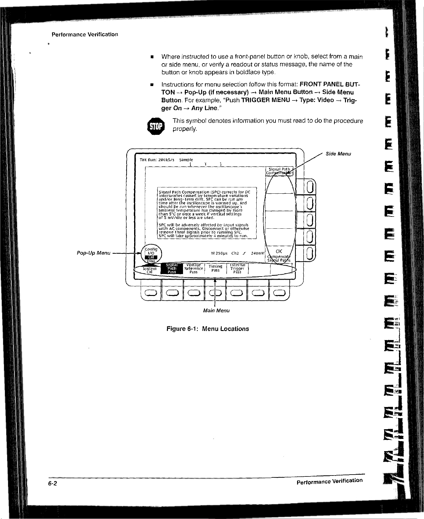
Performance
Verification
•
Where
or
side
buttonorknob
•
Instructions
TON—fPop-Up
Button.
ger
On—pAny
This
0
properly.
instructed to
menu,orverifyareadoutorstatus
for
For
example, “Push
symbol
useafront-panel buttonorknob,
appearsinboldface
menu
selection
(if
necessary)~Main
TRIGGER MENU—+Type: Video—fTrig
Line.”
denotes
information
type.
follow
this
you
message, the
format:
Menu
must
FRONT
Button-~Side
readtodo
select
name of
PANEL
the
fromamain
the
BUT-
Menu
procedure
Side
Menu
-
E
F
F
Pop-Up
Menu
Figure
6-1:
Main
Menu
Menu
Locations
6-2
S
performance Verification

Ia
Performance
Verification
test
2
3
4
5
6
Equipment
Item
Number
Description
1
Termination
50
0
(two required)
Cable,
Coaxial
quired)
Connector, Female-BNCtodual-banana
Dual-Banana
Connector,
BNC
Coupler,
Dual-Input
Generator, DC
Calibration
and
Precision
(two
“T”
Minimum
Impedance
female
output
500,91cm
re-
male BNC
Male-BNCtodual-femaleBNC
Female-BNC to
BNC
Variable
accuracyto0.1%
These
instrument
requirements
Table
Requirements
500;
connectors:
BNC
input,
(36 in),
connectors
dual-male-
amplitude
procedures
performance.Ifyour
6-1:
male BNC
male
to±110V;Data
use
external,
listedinTable
Test
Equipment
Example Purpose
Tektronix
011-0049-01
to
Tektronix
012-0482-00
Tektronix
103-009-00
Tektronix
103-0030-00
Tektronix
067-0525-02
traceable signal sources to
test
6-1,
your
part number
part number
part number
part number
part number
Precision
equipment
test results
8200
directly
does
not
meet
willbeinvalid.
Checking
between
Signal
interconnection
Several
tests
Checking
sensitivity
Checking
between
CheckingDCoffset,
gain,
and
measurement
check
the
minimum
delay
channels
accuracy
trigger
delay
channels
R
R
7
Generator,
Leveled
Wave,
Frequency
8
Generator, Time
Mark
9
Probe,
included
this
instrument
Test
Record
Sine
Medium-
lOX,
with
200
khzto250
amplitude
into500
Variable marker
from10mstoiOns;
accuracy
A
P6109B
TDS 320)orP6111
(TDS
350)
MHz;
from5myto4
frequency
within2ppm
(TDS
310 and
probe
Photocopy
for
your
variable
V
2.~,
B
the
next
instrument.
TEKTRONIXSO503
Sine Wave
TEKTRONIXTOSO1A
Mark
Tektronix
P61098
TDS 320)
P6111B(TDS
page
Generator
Generator
number
(TDS
310 and
or
350)
and
useitto
•
record the
Leveled
Time
accuracy
Checking
sensitivity at
frequencies
Checking
rate
and
accuracy
Signal
interconnec-
tion
performance
trigger
low
sample
delay-time
test
results
itS
310,
TDS
320,&TEDS
350
Instruction
Manual
6-3

Performance
Verification
TDS
310,
TDS
320,
and
TDS
350
Test
Record
Instrument
Serial
Temperature:
DateofCalibration:
Pertormance
CH1
VOLTS/DIV
CH2
VOLTS/DIV
Test
CH1
Number:
DC Voltage
1
V
200
mV
1
50
mV
50mV2
~at5OmV
lOmV
5
my
1
V
200mV +8.28V
50
my1
50mV2
~at50mV
lOmV
5
mV
Minimum
Measurement
±97.1
+8.28
—581
mV
—881
my
+286mV
+54.6mV
—982
mV
+97.1
—581
mV
—881mV
+286mV
-l-54.6mV
—982
mV
Analog
Bandwidth
42.5
mV
Certificate
%:________________________________
RH
Number:_____________________
Technicians
Incoming
Outgoing Maximum
Accuracy
+98.9
V
V
—619
+8.52
V
V
my
—9l9mV
+314mV
+654mV
—998
my
V
+98.9
V
+8.52V
—619
my
—9i9mV
+314mV
+65.4mV
—998
mV
N/A
CH2
Main
Trigger
Main
Trigger—Falling
1
Generator
2
Generator
setat—0.6
setat—0.9
V.
V.
Long
Term
Edge
Sample
Trigger
425
mV
Rate
and
Delay
Time
Accuracy
—2.0
Div
Sensitivity,DCCoupled
stable trigger
stable trigger
N/A
+2.0
N/A
N/A
Div
6-4
performance
Verification

Self
Test
This procedure
and
passes
confirms
adjusted.Notest equipmentorhookups
Equipment Required:
Time
Required: Approximately5minutes.
Prerequisites:
before
Procedure:
1.
2.
3,
4.
doing
Press
The
internal
tion
takes
terns
screen.
Check
ment has failed
procedureonpage
Press
Press
uses
internal
its
internal
that
the
oscilloscope
Powerupthe
this
procedure.
UTILITY—System:
diagnostics
about30seconds. Whileitprogresses,avarietyoftest
flashonscreen. When
that
the
screen reportsnofailures.Ift
the
CLEAR MENU.
UTILITY—System:
routinestoverify
self
tests
and signal
was
adjusted
None.
oscilloscope
Diag—Execute—OK
verify
proper
finished,
self
test, Proceed immediatelytothe
8-30.
Cal.
that
the
path
compensations.Italso
properlyatthe
are
required.
and
allow
oscilloscope
status
messages
reportsafailure,
oscilloscope
timeitwas
a 20
minute
Confirm
function. This
appearonthe
troubleshooting
functions
last
warm-up
Run
Test.
verifica-
pat
the
instru-
-
5.
Check
the
that
Reference,
labels read
immediatelytothe
the
word
Timing,
Fail,
Pass
and
the
instrument
system
appearsinthe main
Ext
Trig
menu
has
failed
calibration procedureonpage
labels.
menu under
(See
Figure
the
self
test,
the
Voltage
6-2.)Ifany
Proceed
7-2.
of
TOS 310, TOS 320,
&
TDS
350
Instruction
Manual
6-5

Figure
6-2:
Verifying
Press
tion
Adjustments
Signal
completes,
Path—~OK
the
and
status
Signal
Path
Compensation
Compensate
message
updatestoPassorFailinthe
Signal Paths.
When
compensa
main
-
Check
(See
that
Figure
the
performance
word
Pass
appears
6-2.)IfPass
does
not
verification; returnitto
under
appear,
Tektronix
Signal
the
instrument
for
Pathinthe
has
servicing
main
failed
menu.
the
Performance
Verification

The
purposeofthis
properly.
procedureisto
Functional
confirm that
the
oscilloscope
Test
functions
R
I
This procedure
features operate.Itdoes
Therefore, when
a
signal
or
interpret
checkedinPerformance
DO
called
other
results.Inthis case, just
If
the
oscilloscope
mance
the
troubleshooting
Equipment
(TDS
350)
probe
verifies
appears
~hasaperiodofabout
the
quantities
NOT
make
changestothe
outinthe
than
verification.Todiagnose
Required: One
(Item
procedure.Ifyou make
those
fails
proceduresonpage
9).
functions; that
the
instructions
on-screen
givenaslimits.
called
outinthe
redo
anyofthese checksithas failed
P61
09B
not
verity
thatisabout
six
horizontal
Tests,
which
front-panel
the
NOTE
the
(TOS
is,itverities
that
they
operate within
that follow
procedure, you
procedure
causesofa
310
call
five
divisions,”
Operation
beginonpage
settings that
changestothese
from
failure,
8-27.
and
TDS 320)orP6111
that
oscilloscope
limits.
for
youtoverify
divisionsinamplitude’
etc.,doNOT
within
limits
6-11.
are not
may obtain
step
1.
the
perfor-
proceed
that
is
settings
invalid
to
B
I
I
I
I
I
3
TDS
310, TOS
320,
&
TOS
350
Instruction
Time Required:
Prerequisites:
Procedure:
1.
Install
the
front
Manual
None.
the
probeonCH1.Connect
panel;
Approximately5minutes.
the
leave
the
probe
ground
probe
tip
to PROBE
unconnected.
(See
COMP
Figure
on
6-3.)
8-7

Functional
Test
Figure
2.
Press
SAVE/RECALL
Factory
3~
Press
4,
Set
waveform
5.
Set
6.
Check
divisionsinamplitudeison
locate
7.
Check
aboutfour
8.
Check
rightonscreen
9.
Press TRIGGER
10.
Check
with
mit.
AUTOSET
the
VOLTS/DIVto1V.Use
verticallyonscreen.
the
SEC/DIV to
thatasquare-wave
the
readout.)
that one
that
that
the
trigger
period
horizontal
the
horizontal
When rotated.
MENU—~Mode—~Normal.
the
trigger
LEVEL
6-3:
Hookup
SETUP—~Recall
15•
250
F
probe-compensation
screen.
of
the
square
divisionsonscreen.
POSITION
level
readout for
knob.
for
the
vertical
(See Figure
wave
knob
Functional
Factory
POSITION
probe~compensatior1
positions
the
main
Test
Setup—*OK Confirm
knobtocenter
signal of about
6-1onpage
the
signal left
trigger
system
five
6-2
to
signal
changes
F
the
F
E
is
and
6-8
11.
Check
wave
12.
Check
just
13.
Press
14.
Check
on-screen,
wave.)
15.
Press
displaysanactively acquiring
detected.”
that
the
trigger-level
signalasyou
that
pressing
left
untriggered.
ACQUIRE—Mode—Sample
that
the
(Note
the
side
rotate
instrument displaysanactively
that
menu
knob
can
trigger
it.
(Leave
SET LEVELTO50%
thereisnoise
button
Peak
the
presentonthe
Detect.
waveform
signal
and
untriggered.)
triggers
acquiring
Check
cii
screen
untrigger
the
peaksofthe
that
with
Performance
the
signal that
waveform
the
instrument
the
noise
Verification
square-
you
square
“peak

16.
Press
the
playsanactively
played.
17.
Press
the
playsanactively
18.
Press
WAVEFORM
19.
PressOH2 and
20.
Repeat
21.
Disconnect
terminal.
side
menu
button
acquiring waveformonscreen
side
menu
button
acquiring
waveformonscreen
OFFtoremove
move
the
probetotheOH2
steps3through17for
the
probe
from
the
Envelope.
Average.
Channel1from
Channel
channel
Check
Check
2.
input
that
the
with
that
the
with
the
input.
and
the PROBE
Functional
instrument
the
noise
instrument
the
noise
display.
Test
dis
-
dis
-
dis
-
reduced.
COMP
R
TDS
ala,
TDS 320,&TDS
350
Instruction
Manual
6-9

Performance
Tests
3
I
Prerequisites
Signal
Acquisition
System Checks
The procedures
Time Base
the
characteristics
Characteristicsonpage
The
testsinthis
performance
•
The cabinet
•
You
must have
on
page
*
The
digitizing
period
temperature between
These
fistedaschecked under
section.
procedures
are
in three
System
of at
Checks,
that
subsection
and
functionality
mustbeinstalled.
performed
6-6
and
those
oscilloscope
least20minutes,
check
groupings: SignalAcquis/tion
and
Triggering
appearinboldface
4-3.
compriseanextensive,
when
and
passed
under
Functional
must
and
—10’~Cand
signal
acquisition
Warranted
Characteristicsinthe
System
type
the
following
the
procedures
Tests,onpage
have
been
mustbeoperatingatan
-i-55~
C.
system
System
Checks.
under
Warranted
valid
confirmation
requirements
operating
characteristics
forawarm-up
Specifications
Checks,
They
check
are
met:
under Self
6-7.
ambient
that
all
of
Tests.,
are
I
I
~1
I
I
Check
Equipment
tion
Time
Prerequisites:
page
Procedure:
I,
DC
Performanceofthis
98
VDC.
suretoset
ing,
disconnecting,
performanceofthis
Required:
generator
Required:
6-11.
Set
the
outputofaDCcalibration
Voltage
Contact
theDCcalibration
(Item
Approximately35minutes.
The
Measurement
WARNING
procedure
with
live
circuits
generatorto0
and/ormoving
procedure.
One dual-banana
6),
and
one
precision
oscilloscope
must
requires
Accuracy
input
could
cause
volts
the
test
hookup
connector (Item
coaxial
meet
generatorto0
cable
the
prerequisites
vo/tagesupto
injuryordeath,
before
volts,
connect
during
the
3),
oneDCcalibra
(Item
2).
listed
Be
-
-
on
TUS
31Q,
TOS
320,
&
TOS
350
Instruction
Manual
6-Il

Pertormance Tests
Dual
BNC
2.
Banana
Adaptec
Connect
connector
in
Figure 6-4
to
the outputofaDCcalibration
followedbya 500precision
Coaxial
Cable
generator
coaxial
cabletoCH1,as
throughadual-banana
shown
Figure
3.
Press
Factory
4.
Press
5.
Press
6.
Press
the
7.
Set
have not
8.
Press
Scale
Setting
1
V
200
mV
6-4:
Hookup
SAVE/RECALL
mit.
ACQUIRE
MEASURE—~Select
the
side
side
menu.
the
VOLTS/DIVtoone of
yet
VERTICAL
Position
Setting
(Divs)
+5
+5
—p Mode
menu
button
Press
checked.
MENU—+Position.
Table
Offset
Setting
+100V
+1OV
for DC
Voltage
SETUP—~Recall
—~
Average
Measurement,
more
until
the
side
menu
button
the
settings
(Start
with
the
6-2:
DC
Accuracy
Generator
Setting
+98V
+8.4V
Measurement
Accuracy Check
Factory Setup-~OK
16.
the
menu
label
Mean.
listedinTable
first setting
listed.)
Accuracy
Limits
+97.1
Vto+98.9V
+8.28Vto
Mean
6-2
+8.52V
Confirm
appears
that you
in
6-12
50
mV
50
mV
~at
50
mV
lOmV
5
mV
—5
—5
—5
0
~1V
—1
OV
—1
—0.6
V
V
—0.9
V
+6OmV
V
—990
mV
—581
—881
+286mVto
+54.6mVto
‘
—982myto
Performance
mVto
mVto
—619
mV
—919
mV
+314
rnV
+65.4mV
—998
mV
VeriticatiOn
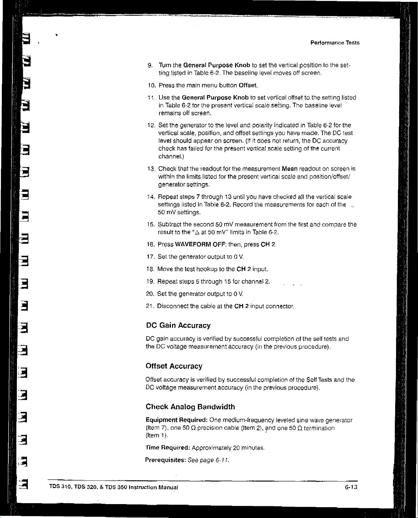
L
.1
15.
9.
Turn
the
ting
10.
11.
12.
13.
14.
listedinTable
Press
the
Use
the
in
Table
remains
Set
the
vertical
level
should appearonscreen.
check
channel.)
Check
within
the
generator
Repeat
settings
50mVsettings.
Subtract
General
main
General
6-2
off
generator to
scale,
has failed
that
limits listed
settings.
steps7through13until
listed in
the
Purpose
6-2. The
menu
button
Purpose
tor
the
screen.
the
present
the
position,
for
the
readout
for
Table
6-2.
second50mV
Knobtoset
baseline
Knobtoset
vertical scale
level
and
offset
present
for
the
the
Record
measurement
the
Offset.
and polarity indicatedinTable
present
level
settings
(Ititdoes
vertical scale settingofthe
measurement
you
have
the
vertical
moves
vertical offsettothe
setting. The
you
have
not return, the DC
Mean
vertical
scale
checked
measurements
from
the
Pertormance
positiontothe
off
screen.
baseline
made.
readoutonscreen
and
position/offset!
all
the
vertical scale
for
eachofth~
first
and
Tests
set
setting listed
level
6-2
for
the
TheDCtest
accuracy
current
compare
the
-
is
•
result
to
the
‘L~at50
16.
Press
WAVEFORM
17.
Set
the
generator
18.
Move
the
test
hookuptothe CH2input.
19.
Repeat
20.
Set
21.
Disconnect
DC Gain
DC
gain
the DC
Offset
Offset
DC
voltage measurement
Check
steps5through15for
the
generator
the
Accuracy
accuracyisverifiedbysuccessful
voltage
measurement accuracy
Accuracy
accuracyisverifiedbysuccessful
Analog
mV’
OFF;
outputto0
outputto0
cableattheCH2
accuracy
Bandwidth
limitsinTable
then, pressCM2.
V.
channel
V
(in
6-2.
2.
input
connector,
completion
(in
the
completionofthe
the
previous
previous
procedure).
of.the
self
procedure).
Sell
Tests
tests
and
and
the
R
TDS
310,
TDS
320,&TOS
350
Instruction
Equipment
(Item
(Item
Time
Prerequisites:
Manual
Required: One
7),
one
500
1).
Required:
medium-frequency
precision
Approximately20minutes.
See
page
cable
6-11.
(Item
2), and
leveled
one500
sine
wave
termination
generator
6-13

Performance
Tests
Procedure:
1.
Connect,
sine
wave
CII
I
(see
frequencyof50
throughaGOD
outputofa
Figure
medium-frequency
6-5).
Set
kHz.
precision
the
outputofthe
cable
anda50Qtermination,
leveled
sine
generator toareterence
wave
generator to
50flTermination
the
E
E
Figure
1.
Press
SAVE/RECALL
Factory
2.
Set
3.
Press
4.
Press
5.
Press
6.
Press
menu
Press
7.
SettheVOLTS/DIVto10my.
8.
Set
9.
Press
10.
Increase
100
11.
Set
(TEDS
12.
Press
mit.
the
SEC/DIV to10ps.
TRIGGER MENU—.Coupling—~Noise
ACQUIRE—Mode—Average
MEASURE—iHigh—Low
the
button
the
the
generator
SET LEVELTO50%asnecessarytotrigger
the
MHz
the
SEC/DIVtoiOns
350).
SET LEVELTO50%a~necessarytotrigger
6-5:
main
menu
more
side
menu
outputsothe
frequencyofthe
(TDS
320),or200
hoOkup
SETUP—~Recall
button
until
button
the
for
Setup—sMm—
Select
menu
Pk-Pk.
CHx Pk-Pk
generator
MHz
(109
(TDS
310),5ns
Analog
label Pk-Pk
Bandwidth Check
Factory
16.
Measurement.
readout
outputto50
350).
(TDS 320),or2.5
Setup
—
OK
Rej.
Max.
Now
press
appearsinthe
equals60mV.
the
display.
MHz
(TDS
the
display.
Confirm
the
side
310),
ns
E
E
side
menu.
6-14
13.
Check
Figure
that
6-6)
the
is
PK-Pk
42.5
readout on
mV
screen
(as
shown
PertorrTlaflce
in
Verification

First,
increase
frequencytothe
frequency;
the
then
decrease
horizontal
reference
test
the
scale.
Performance
Tests
2
Time
Base
Checks
Second,
read
from
measurement
System
the
the
results
readout
of
Pk.Pk.
14.
15.
16.
17.
18.
19.
This
Delayed
When
set
the
Press
Press
Press
Repeat
Disconnect
procedure
time
Characteristicsinthe
Figure
finished
generator
WAVEFORM
CII2and
TRIGGER
6-6:
checking,
output
OFFtoremove
move
the
MENU-.
frequency
steps6through13for
the
test
hookupfrom
checks
base
those
system
and
Specifications
Measuring
set the
Analog
SEC/DIV
backto50
Channel1from
hookuptothe
Source
CH
2.
.-.
CII
the CII2input
characteristics
are
listedaschecked
section.
Bandwidth
backtothe10is
kHz.
the
CH
2
input.
2.
connector.
that
relatetothe Main
under Warranted
settinc.
display.
anc
anc
TDS
310,
los 320,
&
TDS
350
Instruction
Check Long-Term
Equipment
coaxial
Time
Prerequisites:
Manual
Required: One
cable,
(Item2)and one
Required:
Seepage
Approximately 5
Sample
time-marker
6-11.
Rate
500
minutes.
and
Delay
generator
termination
(Item
(Item
Time
8),
1).
Accuracy
one
precis.
~n

Performance
Tests
Procedure:
I.
Connect,
the
time-mark
Figure
6-7.
through
outputofa
Set
the
a 500precision
time-marker
outputofthe
generator
coaxial
cable and
generator toCH1,
for10ms
a 50C)termination,
as Shown
markers,
in
4
2.
3.
4.
5.
6.
7~me-Mark
Generator
Output
Figure
Press
SAVE/RECALL SETUP
Factory
Set
Press
the
Set
Press
hut.
the
VOLTS/DIV
SET
LEVEL
test
signalonscreen.
the
SEC/DIV to1ma.
HORIZONTAL
6-7:
to
TO
r
~ ~_—~1
Hookup
500
50%;
MENU
mV.
use
—i.
for
-.
Recall
the
Tri~g.er
Sample
Factory
vertic~
Position
—
~\ C)
(I,)
~1
~o
~00
Rate
Check
Setup
POSITION
—p
Set
0
50
—~
OK
knobtocenter
to
10%,
a
~,
=
0
00
Q
Termination
Conf~rm
F
7.
8.
Adjust
to
the
vertical
Press
the
button
the
horiz~ntaI
screen.
graticuie
main
Delayed
POSITION
Continue to
line.
menu
button
Only.
to
move
poSitionthe
Time
Base;
the
triggerTto
triggerTto
then
press
the
alignitto
the
side
right
the
menu
and
center
on
6-~
6
Performance
Verification

I
I
9.
Set
General
10.
Set
When
changes
on
11.
Check
graticule
12.
Disconnect
the
SEC/DIVofthe0(delayed)
Purpose
the
SEC/DIVoftheD(delayed)
you
change
to
the
verification
that
the
lineata
the
knobtoset
the
SEC/DIVinstep
10.00001
rising
test
or
edgeofthe
point
within
hookup.
9.99999.
time
baseto1
delay
timeto10
time
baseto500
NOTE
10,
This/s
marker
±2.0
crosses
divisionsofcenter
the
normal
ma.
ms.
delay
and
the
Performance
Then
use
ns.
time
readout
hasnoeffect
center
horizontal
graticule.
Tests
the
Trigger
Checks
System
Delta
Delta
previous procedure.
These
system
Specifications
Check
Equipment
(Item
(Item
Time
Prerequisites:
Time
time measurement
procedures check
and
Edge
Measurement
are
listedaschecked
section.
Trigger
Required:
7),
two
precision
1),
and
one
BNC
Required:
Approximately10minutes.
See
Procedure:
1.
Press
SAVE/RECALL
Factory
mit.
Accuracy
accuracyisverifiedbysuccessful
those
Sensitivity,
One
medium-frequency
500
coaxial
Tconnector
page
6-11.
SETUP-.
characteristics
under
cables
(Item
Recall
that relatetothe
Warranted
DC
Coupled
(Item
4).
Factory
completionotthe
Characteristicsinthe
leveled
2),
sine
one
Setup
wave
500
termination
—~
OK
trigger
generator
Confirm
2.
Set
the
VOLTS/DIV to 500
3.
Set
the
SEC/DIVtoions.
4.
Press
TRIGGER MENU
5.
PressACQUIRE
a.
Connect
a BNC T
500
I
*
one500
connectortothe
cabletothe
—~
cabletothe
othersicleofthe
—~
Mode
my.
Mode—Normal.
—*Averagel6..
outputofthe
other
endofthe
BNC T
connector.
sine
cable.
wave
generator.
Connectasecond
Attach
(c-I-I
TDS
310,
lOS
320,
&
IDa
3S0
Instruction
Manual

Performance
Tests
7,
Connect
EXT
TRIG
the
BNCIconnectortoCII1;connect
input
througha500
termination as
the
cabletothe
shownriFigure
50C~T~rrnin~tI~n
To
6-8.
Ext
E.
Trigger
8.
Set
or
9.
Press
10.
Press
11.
Press
side menu.
12.
Press SET
13.
Set
adjust
the
14.
Press
15.
Press
the
ure
trigger
Figure
the
generator
200
MHz
MEASURE—High-Low
the main
the
the
test
the
amplitudeis500
TRIGGER MENU—~Slope.
SET
test
waveformonboth
a-9).
~Use
LEVEL
6-8;
Hookup
frequencyto50
(lOS
350~.
menu
button
side
menu
button
Press
the
side
LEVELTO50%
signal
amplitude
generator
LEVELTO50%.
output
mV.
the
side
menu to
knobtostabilize
(Readout
the
for
Trigger
MHz
(lOS
Setup—*Mm-Max.
Select
—more—
menu
for
uritil
Check
Measurement.
until
button
Amplitude.
about one
the CII1Amplitude
may
fluctuate
thatastable triggerisobtained
positive and
Switch
the
between
triggerifrequired.)
Sensitivity
310),
Amplitude
divisiononscreen. Fine
negative slopes
100
around
trigger
Check
MHz
(IDS
appearsinthe
readout
slopes;
500
(see
indicates
mV.)
Fig
use
320),
.~1I
for
-
the
j
6-18
Performance
VerlftcatIOfl

First,
setasignal
amplitude at
trigger
with
the
minimum
sensitivity.
Performance Tests
an
Second,
triggeratboth
and
check
negative
forastable
the
slope
settings.
positive
16.
17.
18.
19.
20.
21.
22.
Press
WAVEFORM OFF
PressCH2.
Press
TRIGGER
Disconnect
Set
the
VOLTS/DIVto500
Repeat
Press
steps14and15for
TRIGGER
Figure
6-9:
Measuring Trigger
MENU-.Source-+Ch2.
the
hookup
fromCH1
mV.
Channel
MENU—+Source—*EXT/iD.
and
connectitto
2.
Sensitivity
CII
2.
TDS
310,
TDS
320,&TDS
350
Instruction
23.
Press
24.
Increase
reads
25.
Repeat
26.
Disconnect
Trigger
Trigger
Tests
level
and
Manual
MEASURE—~Select
the
generator amplitude
1.5V
steps14and15for
the
test
hookup.
Level
the DC
Accuracy,DCCoupled
accuracy
is verifiedbythe
voltage
measurement
Measrmnt—~Amplitude.
until
the
amplitude
the
external
trigger.
successful
accuracy
completionofthe
procedureonpage
measurement
Self
6-1
1.
6-19
 Loading...