

Page 1

Programmer Manual
TDS3000, TDS3000B, and TDS3000C Series
Digital Phosphor Oscilloscopes
071-0381-03
For the TDS3000C series, this document applies
to firmware version 4.00 and above.
For the TDS3000 and the TDS3000B series, this
document applies to firmware version 3.00 and
above.
www.tektronix.com
Page 2

Copyright © Tektronix. All rights reserved. Licensed software products are owned by Tektronix or its subsidiaries or
suppliers, and are protec ted by national copyright laws and international treaty provisions.
Tektronix products are covered by U.S. and foreign patents, issued and pending. Information in this publication supercedes
that in all pre viously published material. Specificat ions and pri ce change privileges reserved.
TEKTRONIX and TEK are registered trademarks of Tektronix, Inc.
WaveAlert, and e*Scope are trademarks of Tektronix, Inc.
Contacting Tektronix
Tektronix, Inc.
14200 SW Karl Braun Drive
P.O. Box 500
Beaverton, OR 97077
USA
For product information, sales, service, and technical support:
H In North America, call 1-800-833-9200.
H Worldwide, visit www.tektronix.com to find contacts in your area.
Page 3

Table of Contents
Preface
Related Manuals vii.................................................
Getting Started
Overview of the Manual 1--2...........................................
Communication Modules 1--4..........................................
Installing a Communication Module 1--6.................................
Connector Locations 1--7..............................................
Setting Up Ethernet Remote Communications 1--8.........................
Setting Up GPIB Remote Communications 1--18............................
Setting Up RS-232 Remote Communications 1--21..........................
Comparing GPIB and RS-232 1--26......................................
Command Syntax and Commands
Command and Query Structure 2--1.....................................
Clearing the Oscilloscope Output Queue 2--4..............................
Command Entry 2--4.................................................
Constructed Mnemonics 2--7...........................................
Argument Types 2--8.................................................
Command Groups 2--11.........................................
Acquisition Commands 2--11...........................................
Alias Commands 2--12.................................................
Calibration and Diagnostic Commands 2--13...............................
Cursor Commands 2--14...............................................
Display Commands 2--16...............................................
Ethernet Commands 2--17..............................................
File System Commands 2--18...........................................
Front Panel Commands 2--18...........................................
Hard Copy Commands 2--19............................................
Horizontal Commands 2--19............................................
ITU601 Digital Video Commands (TDS3SDI Only) 2--20.....................
Limit Test Commands (Requires TDS3LIM) 2--21..........................
Mask Commands (TDS3000B Series and TDS3000C Series
with TDS3TMT) 2--22.............................................
Math Commands 2--27.................................................
Measurement Commands 2--28..........................................
Miscellaneous Commands 2--30.........................................
RS-232 Commands 2--32...............................................
Save and Recall Commands 2--32........................................
Status and Error Commands 2--33........................................
Trigger Commands 2--34...............................................
Vertical Commands 2--38..............................................
Waveform Commands 2--39............................................
Command Descriptions 2--45.....................................
TDS3000, TDS3000B, and TDS3000C Series Programmer Manual
i
Page 4

Table of Contents
Status and Events
Appendices
Glossary and Index
Registers 3--1.......................................................
Queues 3--5........................................................
Event Handling Sequence 3--6.........................................
Synchronization Methods 3--7..........................................
Messages 3--12.......................................................
Appendix A: Character Charts A--1..............................
Appendix B: Reserved Words B--1...............................
Appendix C: Interface Specifications C--1.........................
Appendix D: Factory Initialization Settings D--1....................
ii
TDS3000, TDS3000B, and TDS3000C Series Programmer Manual
Page 5

List of Figures
Table of Contents
Figure 1--1: Common message elements 1--2.......................
Figure 1--2: Functional groupings and an alphabetical list of
commands 1--2............................................
Figure 1--3: Service Requests (SRQs) provide for event (interrupt)
driven programs 1--3.......................................
Figure 1--4: Communication module connectors 1--5................
Figure 1--5: TDS3EM LEDs 1--5.................................
Figure 1--6: Communication module mounting location 1--6..........
Figure 1--7: Communication module location 1--7...................
Figure 1--8: The Ethernet Network Settings menu 1--9...............
Figure 1--9: The Change Instrument Settings screen 1--10.............
Figure 1--10: The Ethernet Printer Settings window 1--16.............
Figure 1--11: How to stack GPIB connectors 1--19...................
Figure 1--12: Typical GPIB network configurations 1--19.............
Figure 1--13: Selecting the System: I/O menu 1--20...................
Figure 1--14: The RS-232 connector pin assignments 1--21............
Figure 1--15: RS-232 parameter settings 1--22.......................
Figure 2--1: Command Message Elements 2--2......................
Figure 2--2: Block Argument Example 2--10........................
Figure 3--1: The Standard Event Status Register (SESR) 3--1.........
Figure 3--2: Th e Status Byte Register (SBR) 3--2....................
Figure 3--3: The Device Event Status Enable Register (DESER) 3--3...
Figure 3--4: The Event Status Enable Register (ESER) 3--4...........
Figure 3--5: The Service Request Enable Register (SRER) 3--4........
Figure 3--6: Status and event handling process 3--6.................
Figure 3--7: Command processing without using synchronization 3--8..
Figure 3--8: Processing sequence with synchronization 3--8...........
TDS3000, TDS3000B, and TDS3000C Series Programmer Manual
iii
Page 6

Table of Contents
List of Tables
Table 1-- 1: Communication modules 1--4..........................
T able 1--2: Ethernet Network Settings side menu 1--10...............
T able 1--3: Ethernet Printer Settings side menu 1--12................
Table 1--4: RS-232 adapter cables 1--21............................
Table 1-- 5: RS-232 default settings 1--23...........................
Table 1--6: RS-232 troubleshooting 1--25...........................
Table 1--7: Comparison of GPIB and RS-232 interfaces 1--26.........
Table 2-- 1: BNF Symbols and Meanings 2--1.......................
T able 2--2: Command Message Elements 2--2......................
Table 2--3: Comparison of Header Off and On Responses 2--3........
Table 2-- 4: Acquisition commands 2--11............................
Table 2-- 5: Alias commands 2--12.................................
Table 2--6: Calibration and diagnostic commands 2--13..............
Table 2-- 7: Cursor commands 2-- 14...............................
Table 2-- 8: Display commands 2--16...............................
T able 2--9: Ethernet commands 2--17..............................
Table 2-- 10: File system commands 2--18...........................
Table 2-- 11: Front panel commands 2--18..........................
Table 2-- 12: Hard copy commands 2--19...........................
Table 2-- 13: Horizontal commands 2 --19...........................
Table 2--14: ITU601 commands 2--20..............................
T able 2--15: Limit Test commands 2--21...........................
Table 2-- 16: Mask commands 2--22...............................
Table 2--17: Available TDS3T MT ITU-T G.703 mask standards 2--26..
Table 2--18: Available TDS3TMT ANSI T1.102 mask standards 2--26..
T able 2--19: Math commands 2--27................................
Table 2-- 20: Measurement commands 2--28.........................
Table 2-- 21: Miscellaneous commands 2--30........................
Table 2--22: RS-232 commands 2--32..............................
Table 2--23: Save and Recall commands 2--32.......................
Table 2--24: Status and Error commands 2--33......................
Table 2--25: Trigger commands 2--34..............................
Table 2--26: Vertical commands 2--38..............................
Table 2-- 27: Binary data ranges 2--40..............................
iv
TDS3000, TDS3000B, and TDS3000C Series Programmer Manual
Page 7

Table of Contents
Table 2--28: Waveform commands 2--42...........................
Table 2-- 29: Commands that affect BUSY? response 2--56............
Table 2-- 30: Offset Ranges using a 1x Probe 2--67...................
Table 2--31: CURVE query error conditions 2--90...................
Table 2--32: CURVE command error conditions 2--90................
Table 2--33: DATa and WFMPre parameter settings 2--94............
Table 2--34: XY format pairs 2--104................................
Table 2--35: XY format pairs 2--113................................
Table 2--36: FPAnel:PRESS arguments 2--135.......................
T able 2--37: Advanced Math expression elements 2--199...............
Table 2--38: MATH1: commands 2--205............................
T able 2--39: Commands that Generate an Operation Complete
Message 2--240..............................................
Table 2--40: HDTV formats 2--292.................................
Table 2--41: Video trigger line range values 2--294....................
Table 2--42: TRIGger:DELay commands 2--303......................
T able 2--43: TRIGger:MAIn commands 2--305.......................
Table 2--44: Additional WFMPre commands 2--326...................
Table 3-- 1: SESR bit functions 3--2...............................
Table 3-- 2: SBR bit functions 3--3................................
Table 3--3: No event messages 3--12...............................
Table 3--4: Command error messages -- CME Bit 5 3--12.............
Table 3--5: Execution error messages -- E XE Bit 4 3--14..............
Table 3--6: Device error messages -- DDE Bit 3 3--17.................
T able 3--7: System event messages 3--18............................
Table 3--8: Execution warning messages -- EXE Bit 4 3--18............
Table 3--9: Internal warning messages 3--19........................
Table A--1: Character Set A--1...................................
Table A--2: ASCII & GPIB Code Chart A--3.......................
Table C-- 1: Supported standard interface messages C--2.............
Table D--1: Factory initialization settings D--1......................
TDS3000, TDS3000B, and TDS3000C Series Programmer Manual
v
Page 8

Table of Contents
vi
TDS3000, TDS3000B, and TDS3000C Series Programmer Manual
Page 9

Preface
Related Manuals
This manual documents the commands for remotely controlling your oscilloscope. With this information, you can write computer programs to perform
functions, such as setting the front--panel controls, taking measurements,
performing statistical calculations, or exporting data for use in other programs.
The following documents are available for download from the Manuals Finder
Web site at www.tektronix.com:
TDS3000C Series Digital Phosphor Oscilloscopes User Manual. Information
about installing and operating your oscilloscope.
TDS3000C Series Digital Phosphor Oscilloscopes Technical Reference.
Oscilloscope specifications and a performance verification procedure.
TekVISA Programmer Manual. Description of TekVISA, the Tektronix
implementation of the VISA Application Programming Interface (API).
TekVISA is industry--compliant software for writing interoperable oscilloscope
drivers in a variety of Application Development Environments (ADEs).
TDS3000B Series Digital Phosphor Oscilloscopes User Manual. Information
about installing and operating your oscilloscope.
TDS3000B Series Digital Phosphor Oscilloscopes Technical Reference.
Oscilloscope specifications and a performance verification procedure.
TDS3000, TDS3000B, and TDS3000C Series Programmer Manual
vii
Page 10

Preface
viii
TDS3000, TDS3000B, and TDS3000C Series Programmer Manual
Page 11

Getting Started
You can write computer programs that remotely set the oscilloscope front panel
controls or that take measurements and read those measurements for further
analysis or storage.
To get you started with programming the oscilloscope, this section includes the
following:
H Overview of the Manual summarizes the type of programming information
contained in each major section of this manual (page 1--2).
H Installing a Communication Module provides instructions to install one of
the optional communication modules (page 1-- 6).
H Connector Locations shows the RS-232 and GPIB connector locations on
the back panel of the TDS3000B and TDS3000C oscilloscopes (page 1--7).
H Setting Up Ethernet Remote Communications describes setting up for
Ethernet 10baseT remote control, including connecting the oscilloscope and
setting the appropriate front-panel controls (page 1--8).
H Setting Up GPIB Remote Communications describes setting up for GPIB
remote control, including connecting the oscilloscope and setting the
appropriate front-panel controls (page 1--18).
H Setting Up RS-232 Remote Communications describes setting up for RS-232
remote control, including connecting the oscilloscope and setting the
appropriate front-panel controls (page 1--21).
H Comparing GPIB and RS-232 compares the characteristics of the GPIB and
RS-232 interfaces (page 1--26).
TDS3000, TDS3000B, and TDS3000C Series Programmer Manual
1- 1
Page 12
Getting Started
Overview of the Manual
The information contained in each major section of this manual is described
below.
Syntax and Commands
Application Menu Commands
Zoom
Alias Commands
A
A
A
A
A
A
A
Acquisition Commands
A
A
ACQuire:MODe
A
ACQuire:NUMACq?
A
ACQuire:NUMAVg
A
ACQuire:NUMEnv
A
A
ACQuire:STATE
ACQuire:STOPAfter
The Syntax and Commands chapter describes the structure and content of the
messages your program sends to the oscilloscope. Figure 1--1 shows a syntax
diagram and command parts as described in the Command Syntax subsection.
Command Parts
Header
Comma
SAVe:WAVEform CH1,REF3
Mnemonics
Figure 1- 1: Common message elements
Chapter 2 also describes the effect of each command and provides examples of
how you might use it. The Command Groups section provides a list by functional area. The Command Descriptions section arranges commands
alphabetically (Figure 1--2).
ACQuire:NUMACq? (Query Only)
Zoom
ACQuire:MODe
S
G
S
G
E
E
ArgumentsSpace
ACQuire? (Query Only)
Syntax:...
Group:...
Examples:...
Commands Grouped in Functional Areas Commands Listed Alphabetically
and
Figure 1- 2: Functional groupings and an alphabetical list of commands
1- 2
TDS3000, TDS3000B, and TDS3000C Series Programmer Manual
Page 13
Getting Started
Status and Events
Your program may request information from the oscilloscope. The oscilloscope
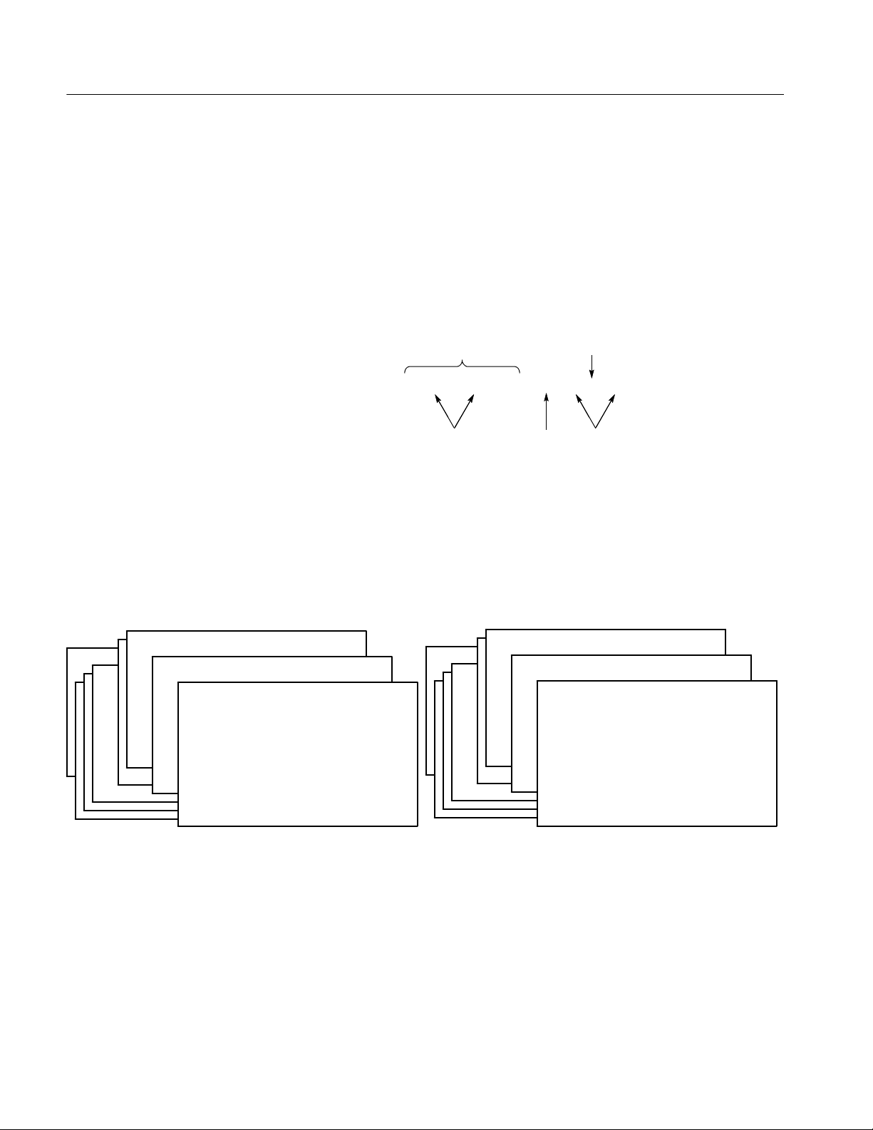
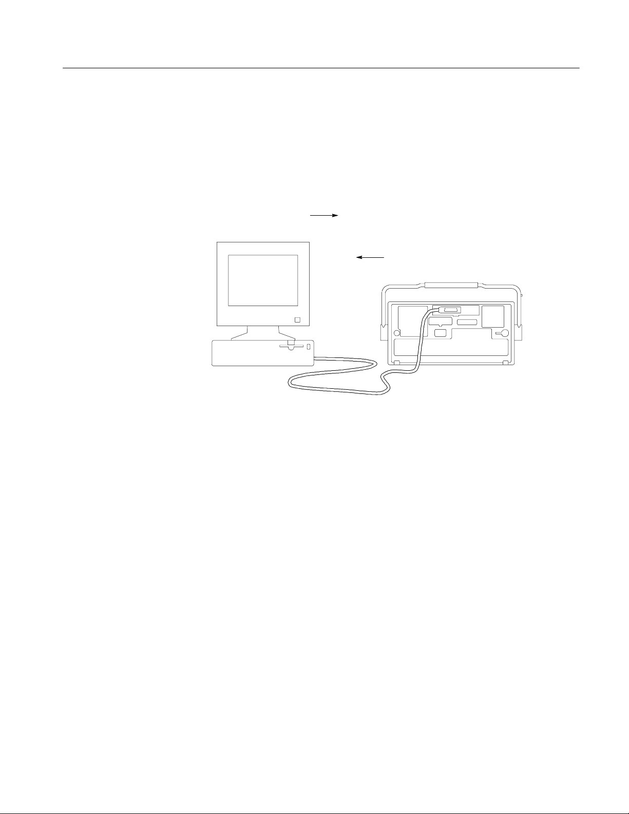
provides information in the form of status and error messages. Figure 1--3 on
page 1--3 illustrates the basic operation of this system.
The Status and Events chapter starting on page 3--1 describes how to use service
requests (SRQs) and various event messages in your programs.
Your program requests
status and event reports
as the Controller.
The oscilloscope sends status and
event reports using a communications
module or the Ethernet port built--in on
TDS3000B/TDS3000C series models.
GPIB Cable
Figure 1- 3: Service Requests (SRQs) provide for event (interrupt) driven programs
TDS3000, TDS3000B, and TDS3000C Series Programmer Manual
1- 3
Page 14

Getting Started
Communication Modules
Communication modules let you communicate with, or remotely control, your
TDS3000, TDS3000B, and TDS3000C Series oscilloscopes.
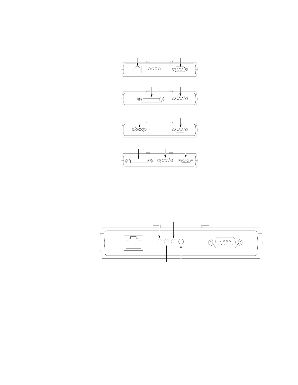
Table 1--1 lists the available communication modules. Figure 1--4 shows the
connector configuration for each module.
Table 1- 1: Communication modules
Communication module
TDS3EM This communication module adds Ethernet 10baseT local area network
TDS3GM This communication module adds GPIB and RS-232 ports to all TDS3000
Description
(LAN) and RS-232 ports to your TDS3000 Series oscilloscope. You can use
the Ethernet port for remote programming or printing to a LAN printer.
Communication modules are user-instal lable. All TDS3000B Series and
TDS3000C oscilloscopes have a built-in Ethernet port.
oscilloscopes. You can attach a printer to these ports or use them for remote
programmability. Communication modules are user-installable.
TDS3VM This communication module adds VGA and RS-232 ports to all TDS3000
oscilloscopes. You can attach a printer to the RS-232 port or use it for
remote programmability. You can attach a monitor to the VGA port to
enhance viewing the screen from a distance. Communication modules are
user-installable.
TDS3GV This communication module adds VGA, GPIB, and RS-232 ports to all
TDS3000 oscilloscopes. You can attach a printer to these ports or use them
for remote programmability. You can attach a monitor to the VGA port to
enhance viewing the screen from a distance. Communication modules are
user-installable.
1- 4
TDS3000, TDS3000B, and TDS3000C Series Programmer Manual
Page 15
Getting Started
RS-232
RS-232
RS-232
VGA
TDS3EM
TDS3GM
TDS3VM
TDS3GV
Ethernet
VGA
GPIB
GPIB
RS-232
Figure 1- 4: Communication module connectors
The TDS3EM Ethernet Communication Module (TDS3000 Series only) has a set
of four status LEDs. Figure 1--5 identifies each LED and describes its purpose.
LINKTXRX
CLSN
LINK: Indicates Ethernet connection when lit.
TX: On when oscilloscope is transmitting data.
RX: On when oscilloscope is receiving data.
CLSN: On when oscilloscope is attempting to transmit and receive at the same time.
Figure 1- 5: TDS3EM LEDs
TDS3000, TDS3000B, and TDS3000C Series Programmer Manual
1- 5
Page 16
Getting Started
Installing a Communication Module
CAUTION. To avoid damage to the oscilloscope or communication module,
observe all ESD precautions described in the User manual.
NOTE. Do not install a TDS3EM module into a TDS3000B Series or TDS3000C
Series oscilloscope. Installing the TDS3EM module will cause both the built-in
Ethernet port and the module’s Ethernet port to stop functioning.
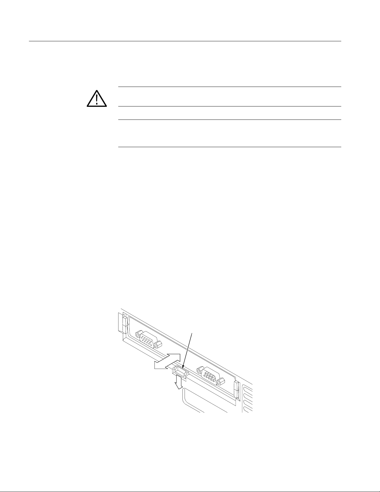
To install one of the optional communication modules, follow these steps:
1. Turn the oscilloscope power off.
2. Push down on the latching tab to remove the blank cover.
3. Slide the communication module into the compartment until the internal
connectors are seated and the latching tab locks.
4. Turn power on. The communication module is now ready for your use.
To remove a communication module, follow these steps:
1. Turn the oscilloscope power off.
2. Push down on the latching tab and then use a small screwdriver to alternately
pry out the sides of the communication module.
3. Slide out the communication module and store it in an ESD-shielded bag
Install the blank cover if no other communication module is to be installed.
Latching tab
1- 6
Figure 1- 6: Communication module mounting location
TDS3000, TDS3000B, and TDS3000C Series Programmer Manual
Page 17
Connector Locations
Getting Started
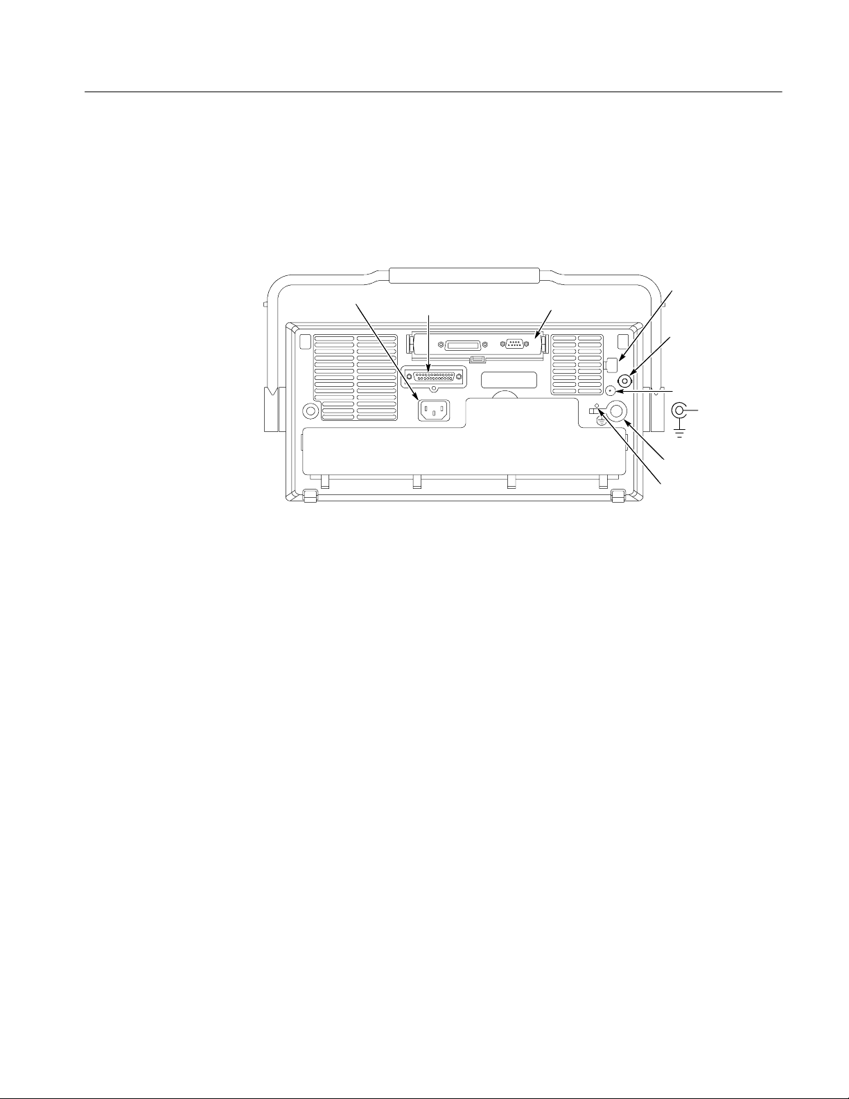
Figure 1--7 shows the location of the installed communication module, as well as
the rear-panel connectors. The built-in Ethernet port and External trigger are only
available with the TDS3000B and TDS3000C Series models.
Power input
Parallel printer port
TDS3000/TDS3000B
Communication Module
Figure 1- 7: Communication module location
Ethernet port
TDS3000B/TDS3000C
External trigger
TDS3000B/TDS3000C
DC power output
TDS3000/TDS3000B
+14.2 V DC
≤400 mA
Ground terminal
CAL switch
TDS3000, TDS3000B, and TDS3000C Series Programmer Manual
1- 7
Page 18

Getting Started
Setting Up Ethernet Remote Communications
The following sections describe how to set up the Ethernet communications for
network hard copy printing and remote programmability. The Ethernet port
requires a straight-through 10BaseT cable with RJ-45 connector. No transceiver
is necessary .
Contacting Your Network
Administrator
Ethernet Setup Form for
Ethernet Hardware address : ::::
(User: copy this address from the UTILITY > System: I/O > Ethernet Network Settings > Change Instrument Settings
screen before sending this form to the network administrator)
Type of IP address requested: Dynamic (DHCP/BOOTP) - Static -
(User: See page G--1 of the TDS3000C Series DPO Oscilloscope User Manual for information on dynamic and static IP
addresses)
Settings (from network admin.):
1
Instrument Name___________________
Instrument (IP) Address______.______.______.______
Domain Name: __________________________
DNS IP Address: ______.______.______.______
Gateway IP Address: ______.______.______.______
Subnet mask ______.______.______.______
HTTP Port:________
To connect the oscilloscope to the network, you need to obtain information from
your network administrator. For your convenience, make two photocopies of the
form shown below and send them to your network administrator to fill in. The
administrator can then return one copy and keep the other copy for filing.
1- 8
2
(User: Enter these values on the UTILITY > I/O > Ethernet Network Settings > Change Instr ument Settings
screen)
Network Administrator: Please provide network information about the
following printer:
Printer Location: ____________________________________________
Printer Make: _________________ Model: ______________________
(User: fill in above printer information before sending form)
Printer Network Name: ______________
Printer Server Name: ________________
Print Server IP Address: _____._____._____._____
(User: Enter above information on the UTILITY > I/O > Ethernet Printer Settings > Add Printer screen.
TDS3000, TDS3000B, and TDS3000C Series Programmer Manual
Page 19
Getting Started
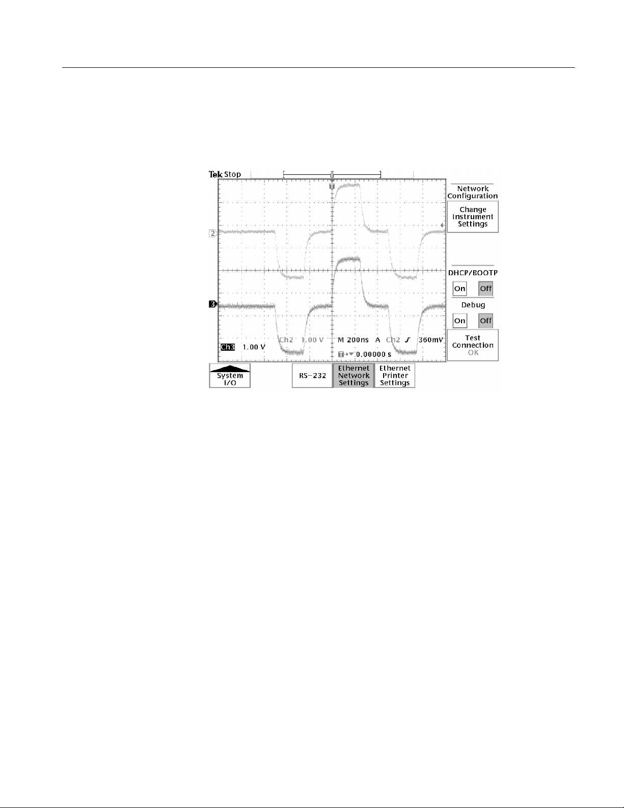
The Ethernet Menus
Push the UTILITY button, then push the System bottom button to select I/O.
The oscilloscope displays the I/O menu, as shown in Figure 1--8, which contains
the Ethernet Network Settings and Ethernet Printer Settings bottom buttons.
Figure 1- 8: The Ethernet Network Settings menu
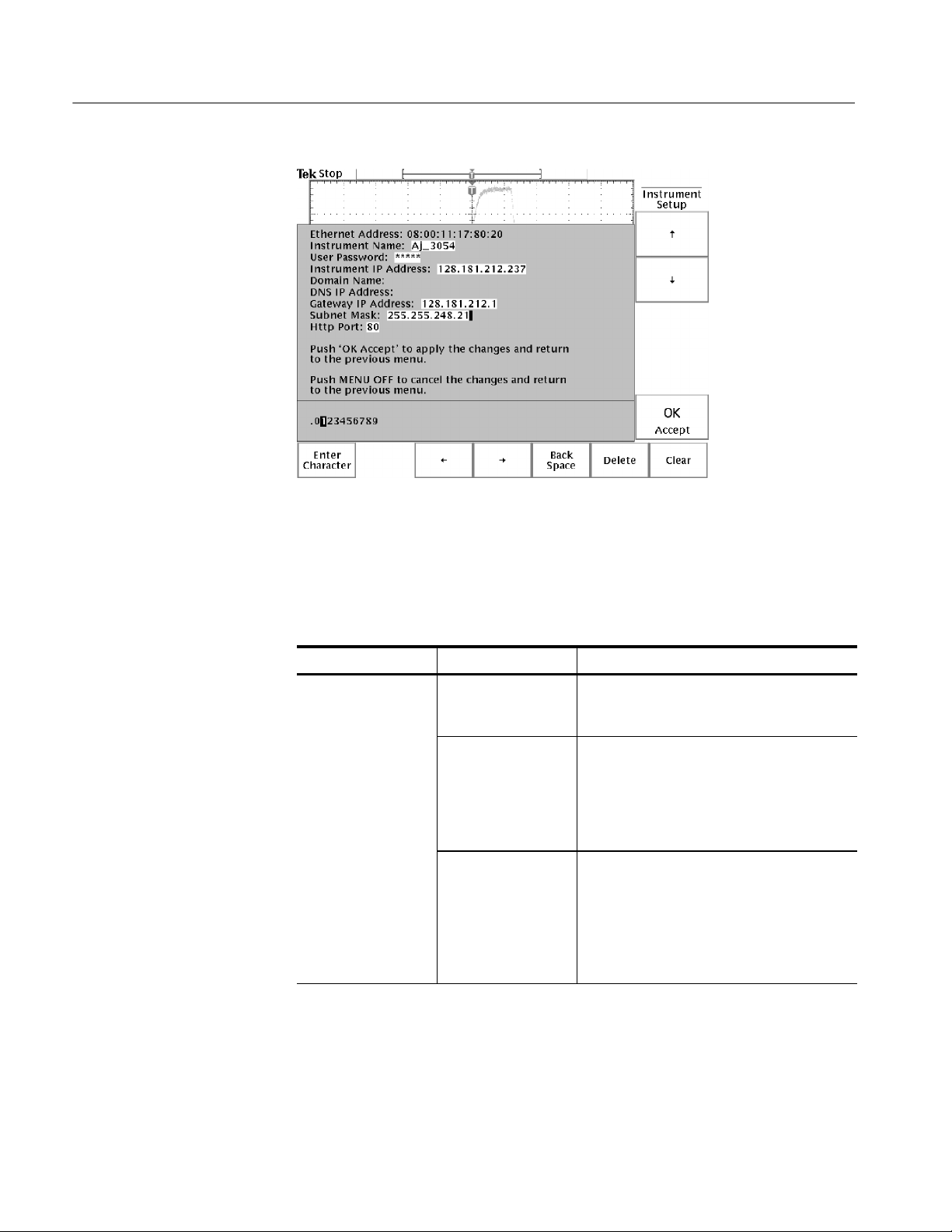
Ethernet Network Settings Menu. Figure 1--9 shows the Ethernet Change
Instrument Settings screen. Table 1--2 describes the Ethernet Network Settings
fields. The procedures on page 1--13 (for networks that support DHCP/BOOTP)
and 1--14 (for networks that do not support DHCP/BOOTP) describe how to set
up the oscilloscope to communicate on your network using the appropriate
instrument IP information from your network administrator.
TDS3000, TDS3000B, and TDS3000C Series Programmer Manual
1- 9
Page 20
Getting Started
Figure 1- 9: The Change Instrument Settings screen
Table 1- 2: Ethernet Network Settings side menu
Side Field/value Description
Change Instrument
Settings
Ethernet Address: The factory-set Ethernet address for this
module or instrument. This field cannot be
edited.
Instrument Name: An alphanumeric label assigned to the
oscilloscope for easier network reference.
Check with your network administrator to
determine instrument name restrictions and
that the instrument name you request does not
already exist.
User Password: A password that causes the oscilloscope
e*Scope web server to prompt for user
authentication before allowing ethernet
access. Access is permitted for the duration of
the network browser session. Leaving this
blank allows any browser to access the
oscilloscope.
1- 10
TDS3000, TDS3000B, and TDS3000C Series Programmer Manual
Page 21

Table 1- 2: Ethernet Network Settings side menu (Cont.)
Side DescriptionField/value
Change Instrument
Settings (cont.)
Instrument IP
Address:
Domain Name: The name of the domain to which the
A unique Internet Protocol (IP) address that
identifies the oscilloscope. You must enter an
IP address in order for the oscilloscope to
communicate with the network. Obtain an
instrument IP address from your network
administrator.
If your network supports DCHP/BOOTP
protocols, then you can also set DCHP/
BOOTP to ON and let the oscilloscope
automatically obtain a dynamic IP address
from the network. Dynamic IP addresses can
change each time the oscilloscope is turned
on.
oscilloscope is attached. Although not required
to communicate with the network, the domain
name is used to assist with printer communications. Obtain the domain name (if
necessary) from your network administrator.
Getting Started
DNS IP Address: The IP address of the domain name system
(DNS). Although not required to communicate
with the network, the DNS IP address is used
to assist with printer communications. Obtain
the DNS IP address (if necessary) from your
network administrator.
Gateway IP Address: Obtain the gateway IP address from your
network administrator.
Subnet Mask: Obtain the subnet mask value from your
network administrator.
HTTP Port: The HTTP Port field sets the network http
socket value for the oscilloscope. This field
lets you set up the oscilloscope as an e*Scope
web server on a port ot her than the default
port 80. This is useful for avoiding conflicts
with existing web servers that use the same IP
address through a router.
DHCP/BOOTP On Off Enables or disables Dynamic Host Configura-
tion Protocol (DHCP) and BOOTP support.
DHCP is software that automatically assigns
IP addresses to devices logging onto the
network. Your network administrator can tell
you whether DHCP/BOOTP should be on or
off.
TDS3000, TDS3000B, and TDS3000C Series Programmer Manual
1- 11
Page 22

Getting Started
Table 1- 2: Ethernet Network Settings side menu (Cont.)
Side DescriptionField/value
Debug On Off Helps in debugging network communications
problems by displaying the last 30 characters
transmitted and received by the oscilloscope.
Only displays information when receiving and
responding to remote commands or software
such as WaveStar for Oscilloscopes (TDS3000
Series, TDS3000B Series only).
Test Connection Pushing this button tests the oscilloscope
connection to the Ethernet. The oscilloscope
effectively “pings” the network to locate itself.
While testing, the menu displays Testing... .If
the oscilloscope can locate itself on the
network, the menu displays OK.Ifthe
oscilloscope cannot locate it self, the menu
displays No Response.
Table 1--3 describes the Ethernet Printer Settings menu. The procedure on
page 1--15 describes how to enter network printer settings. Note that you do not
need to be connected to the network to add printer setup information.
Table 1- 3: Ethernet Printer Settings side menu
Side Field/value Description
Add Printer Printer Name The name of a print er queue on the desig-
nated print server. Obtain this information from
your network administrator.
Server Name The name of the server running the printer
queue software.
your network administrator.
Server IP address The IP address of the server running the
printer queue software.
tion from your network administrator.
Rename Printer Selected printer in list Lets you edit the selected printer’s settings.
Delete Printer Selected printer in list Deletes the selected printer information from
the oscilloscope.
Confirm Delete On Off Enables or disables the oscilloscope from
displaying a confirmation window before
deleting a printer configuration.
1
If you have set the domain name and DNS IP address in the Change Instrument
Settings of the Ethernet Network Settings menu, then all you need to enter is either
the server name or the server IP address. The DNS server will look up the missing
information.
1
Obtain this information from
1
Obtain this informa-
1- 12
TDS3000, TDS3000B, and TDS3000C Series Programmer Manual
Page 23

Getting Started
Setting the Oscilloscope
Ethernet Parameters
You need to set two types of Ethernet parameters for the oscilloscope; the
oscilloscope IP address and one or more remote printer addresses. The oscilloscope IP address uniquely identifies the oscilloscope to other devices on the
network, and is required for the oscilloscope to communicate over the network.
The remote printer addresses enable you to send hard copy printouts to a
specified network printer. You can store multiple network printer configurations.
Ethernet Network Settings: DHCP/BOOTP supported. The purpose of a DHCP
(Dynamic Host Configuration Protocol) or BOOTP (Boot Protocol) server is to
issue an IP address to a network device that requests an address. The IP address
enables that device to communicate with the network. This is similar to the
personal computer Plug&Play concept.
The following procedure assumes you have installed the TDS3EM Communication Module and cable into a TDS3000 Series oscilloscope.
For TDS3000B and TDS 3000C series oscilloscopes, a RJ-45 connector, with
10BaseT cable attached to the oscilloscope Ethernet port, is required.
If your network supports DHCP/BOOTP, perform the following steps:
1. Power on the oscilloscope.
2. Push the UTILITY front panel button.
3. Push the System screen button to select I/O.
4. Push the Ethernet Network Settings screen button.
5. Push the Change Instrument Settings side button to display the Instrument
Setup dialog box.
6. Push the DHCP/BOOTP side button to select On. The screen displays the
clock icon while it is talking with the network to obtain an IP address for the
oscilloscope. This step should only take a few moments, but the actual time
will vary depending on your network. The clock icon disappears when the
task is finished.
To verify that the network assigned an IP address to the oscilloscope, push
the Change Instrument Settings side button to display the oscilloscope
Ethernet settings. The instrument IP address field should now be filled in.
If the instrument IP address field is blank, then the oscilloscope was not able
to obtain an IP address from the network. Contact your network administrator for help.
TDS3000, TDS3000B, and TDS3000C Series Programmer Manual
1- 13
Page 24

Getting Started
NOTE. If the DHCP/BOOTP server assigns a dynamic IP address, then the value
in the Instrument IP Address field may be different each time you power on the
oscilloscope. This is not a problem if you are mostly sending hard copy to a
network printer. However, if you intend to remotely control the oscilloscope, a
static IP address is more convenient, as the oscilloscope IP address does not
change, making it easier for remote devices to access the oscilloscope.
Ethernet Network Settings: DHCP/BOOTP Not Supported. If your network does not
support DHCP/BOOTP, you must enter the Ethernet settings manually. You can
obtain these settings from your network administrator by using the form on
page 1--8.
The following procedure presumes that you have installed the TDS3EM
Communication Module and cable into a TDS3000 Series oscilloscope.
TDS3000B and TDS3000C series oscilloscopes simply require an RJ-45
connector with 10BaseT cable attached to the oscilloscope Ethernet port.
Do these steps to enter the Ethernet parameters:
1. Use the Ethernet network setup form on page 1--8 to request the necessary
network information from your network administrator.
2. Power on the oscilloscope.
3. Push the UTILITY front panel button.
4. Push the System screen button to select I/O.
5. Push the Ethernet Network Settings screen button.
6. Push the Change Instrument Settings side button to display the Instrument
Setup dialog box.
7. Push the side menu ↑and ↓ buttons to select a field to edit.
8. Enter the required information from the Ethernet network setup form into
each field:
H The general purpose knob selects a character in the character list. The list
of available characters changes depending on which field is selected.
H The Enter Character button enters the selected character from the
character list at the cursor position in the current field. You can also use
the SELECT button next to the general purpose knob to enter the
selected character .
1- 14
H The ← and → buttons move the cursor left or right in the current field.
TDS3000, TDS3000B, and TDS3000C Series Programmer Manual
Page 25

Getting Started
H The Back Space button deletes the character to the left of the cursor
position in the field.
H The Delete button deletes the character at the cursor position in the field.
H The Clear button deletes all characters from the current field.
9. Push the OK Accept side button to apply the field settings. Push the MENU
OFF button to exit from the menu without applying any changes.
10. Push the Test Connection side menu button to verify that the Ethernet
settings are correct and that the oscilloscope can locate itself on the network.
11. If the oscilloscope does not establish a connection to the network, check that
you correctly entered the Ethernet instrument settings, and that you have
connected the oscilloscope to the Ethernet connector with an appropriate
10baseT cable. If the settings and cable are correct, contact your network
administrator for help.
Ethernet Printer Settings. This procedure presumes that you have successfully
established communications with the network by using one of the previous
procedures.
Do these steps to add a network printer to the oscilloscope (you can store up to
21 printers in the Ethernet network printer list):
1. Obtain the printer name, server name, and server IP address of the network
printer or printers to which you are sending hard copy data.
2. Power on the oscilloscope.
3. Push the UTILITY menu button.
4. Push the System screen button and select the I/O System.
5. Push the Ethernet Printer Settings screen button. The oscilloscope displays
the Printer Configuration window, as shown in Figure 1--10.
6. Push the Add Printer screen button to display the Add Printer dialog box.
7. Push the side menu ↑and ↓ buttons to select a field to edit.
8. Enter the required information into each field:
H The general purpose knob selects a character in the character list. The list
of available characters changes depending on which field is selected.
H The Enter Character button enters the selected character from the
character list. Y ou can also use the SELECT button next to the general
purpose knob to enter the selected character.
H The ← and → buttons move the cursor left or right in the current field.
TDS3000, TDS3000B, and TDS3000C Series Programmer Manual
1- 15
Page 26

Getting Started
Figure 1- 10: The Ethernet Printer Settings window
H The Back Space button deletes the character to the left of the cursor
position in the field.
H The Delete button deletes the character at the cursor position in the field.
H The Clear button deletes all characters from the current field.
9. Push the OK Accept side button to apply the field settings. Push the MENU
OFF button to exit from the Add Printer menu without applying any
changes. You do not need to power cycle the oscilloscope to apply printer
settings; you can select and use newly-entered printers immediately.
10. Select a network printer in the Ethernet printer list. You select a printer by
using the general purpose knob to highlight a printer name in the list.
11. Push the MENU OFF button to exit from the System I/O menus.
12. Push UTILITY > System: Hard Copy > Port to verify or set the printer
port to Ethernet.
13. Verify or set the printer format. Verify that the current oscilloscope hard copy
format can print on your network printer.
1- 16
14. Set Inksaver to ON to print the oscilloscope screen as a black on white
background image.
15. Push the MENU OFF button to exit from the System Hard Copy menu.
TDS3000, TDS3000B, and TDS3000C Series Programmer Manual
Page 27

Getting Started
16. Test the network printer by pressing the hard copy button. The printer should
print the current screen. If the printer does not print the screen, check the
following:
H Hard copy port is set to Ethernet.
H Hard copy file format is compatible with the network printer.
H The printer IP and server information you entered is correct.
H The network printer is powered on and is online.
17. To print to a different network printer, push UTILITY > System: I/O >
Ethernet Printer Settings, and use the general purpose knob to select a
network printer. Make sure that you also set/verify the hard copy file format
when you change network printers.
Ethernet Error Messages
The following error conditions can occur when you are having network
problems. Read the text that follows to help rectify the problem.
Print Server Not Responding. This notifier displays when the oscilloscope
attempts to send data to the selected network printer but the network refuses the
connection to the network printer. This usually means that the network printer
server is offline or the print server IP address is incorrect.
If DNS is available then you can verify the network print server data by entering
the printer name and either (but not both) the print server name or the IP address.
The DNS protocol will fill in the missing data if the user-supplied data is correct.
If DNS is not available, then contact your network administrator for help.
Printer Not Responding. This notifier displays when the oscilloscope attempts to
send data to the selected network printer but the print server is unable to forward
the data to the network printer. This usually means that the network printer is
offline or the printer name is incorrect. Contact your network administrator to
obtain the correct printer queue name.
DNS Server Not responding. This notifier displays when either the Domain
information (Domain name or IP address) is not correct, or the print server name
or printer server IP address is not validated (via the Domain Name Server).
DNS Protocol
TDS3000, TDS3000B, and TDS3000C Series Programmer Manual
You enable DNS protocol by entering the DNS IP address and the domain name
using the Ethernet Network Setup menu. DNS enables the oscilloscope to query
the network for either the name of a device with a specified IP address, or the IP
address of a named device. DNS fills in missing settings when you enter partial
printer configuration information.
1- 17
Page 28

Getting Started
Ethernet, VISA, and
TekVisa
The VISA standard, developed by the VXI plug & play Systems Alliance,
provides a common Input/Output (I/O) library for software developers so that
software from different vendors can run on the same platform. All applications
that communicate with the Ethernet must use a VISA.
A Tektronix version of VISA, referred to in this document as TekVisa, is
available for download from the www.tek.com Web site.
NOTE. If you are connecting the oscilloscope to a network only to print screen
hard copy data, or if you are using e*scope capabilities in a browser, you do not
need to install or configure a VISA.
Setting Up GPIB Remote Communications
The TDS3GM and TDS3GV communication modules have D-type shell GPIB
connectors that conform to IEEE Std. 488.1-1987 standards. Attach an IEEE Std
488.1-1987 GPIB cable (available from Tektronix as part number 012-0991-00)
to this connector. If needed, you can stack GPIB connectors as shown in
Figure 1--11.
GPIB Requirements
Follow these rules when you connect your oscilloscope to a GPIB network:
H Assign a unique device address to each device on the bus. No two devices
can share the same device address.
H Do not connect more than 15 devices to any one bus.
H Connect one device for every 2 meters (6 feet) of cable used.
H Do not use more than 20 meters (65 feet) of cable to connect devices.
H Turn on at least two-thirds of the devices on the network while using the
network.
H Connect the devices on the network in a star or linear configuration as shown
in Figure 1--12 on page 1--19. Do not use loop or parallel configurations.
H Avoid using GPIB address 0. This is typically reserved for controllers.
Appendix C: Interface Specifications gives more information on the GPIB
configuration of the oscilloscope. If needed, you can stack GPIB connectors as
shown in Figure 1--11.
1- 18
TDS3000, TDS3000B, and TDS3000C Series Programmer Manual
Page 29
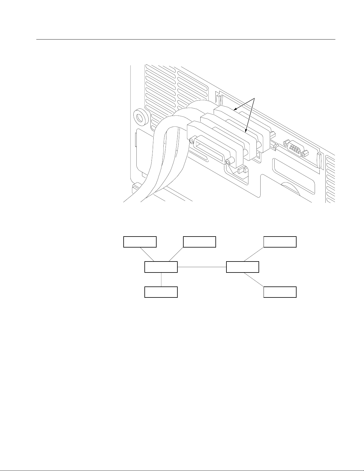
GPIB connectors
Getting Started
Figure 1- 11: How to stack GPIB connectors
GPIB Device
GPIB Device
GPIB Device
GPIB Device
GPIB Device
GPIB Device
GPIB Device
Figure 1- 12: Typical GPIB network configurations
Appendix C: Interface Specifications gives more information on the GPIB
configuration of the oscilloscope.
TDS3000, TDS3000B, and TDS3000C Series Programmer Manual
1- 19
Page 30
Getting Started
Setting the GPIB
Parameters
You need to set the GPIB parameters of the oscilloscope to match the configuration of the bus. Once you have set these parameters, you can control the
oscilloscope through the GPIB interface.
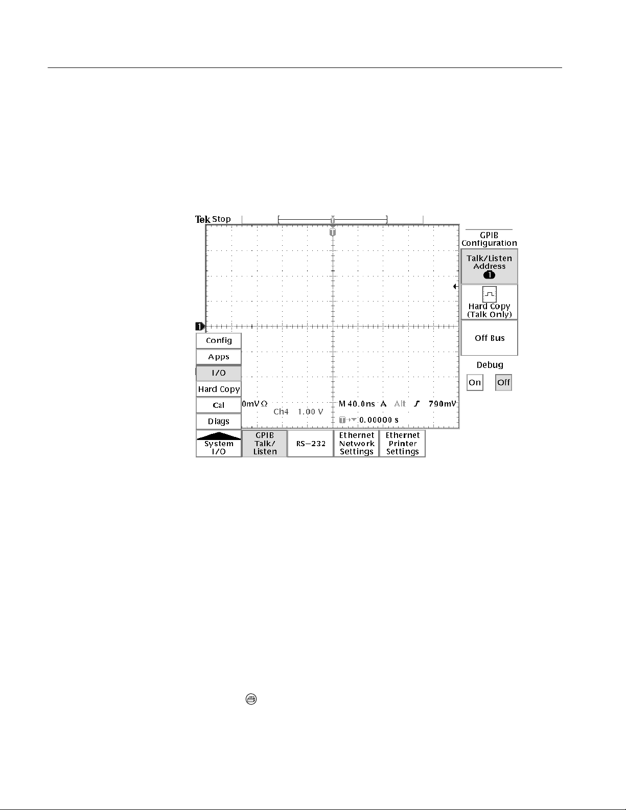
1. Push the UTILITY menu button.
2. Push the System screen button and select the I/O System. See Figure 1--13.
1- 20
Figure 1- 13: Selecting the System: I/O menu
3. Push the GPIB screen button.
4. Push the Talk/Listen Address screen button and use the general purpose
knob to set the Address.
The oscilloscope is set up for bidirectional communication with your controller.
If you want to isolate the oscilloscope from the bus:
H Push the Off Bus screen button. This disables all communication with the
controller.
If you want to enter a special mode of operation to communicate directly with
non-488.2 hard copy devices:
H Select the Hard Copy (Talk Only) screen button, then push the hard copy
button
to have the oscilloscope send hard copy information to a printer.
TDS3000, TDS3000B, and TDS3000C Series Programmer Manual
Page 31

Setting Up RS-232 Remote Communications
All TDS3000, TDS3000B, and TDS3000C Series communication modules have
a 9-pin D-type shell RS-232 connector, as shown in Figure 1--4 on page 1--5.
The RS-232 interface provides a point-to-point connection between the
oscilloscope and equipment such as a computer or terminal. This section tells
how to connect and set up the oscilloscope for communication over the RS-232
interface.
Getting Started
Connecting to an RS-232
Device
The RS-232 standard defines two device types: Data Terminal Equipment (DTE)
and Data Communications Equipment (DCE). The TDS3000B and TDS3000C
series is a DTE device. In standard usage, DTE devices have a male connector,
and DCE devices have a female connector. You should use a straight-through
female-to-male cable of less than 50 feet for a local DTE-to-DCE connection.
Figure 1--14 shows the 9-pin connector with its pin number assignments.
1 No connection
2 Receive data (RxD) (input)
12345
67 8 9
3 Transmit data (TxD) (output)
4 Data terminal ready (DTR) (output)
5 Signal ground (GND)
6 Data set ready (DSR) (input)
7 Request to send (RTS) (output)
8 Clear to send (CTS) (input)
9 No connection
Figure 1- 14: The RS-232 connector pin assignments
In terms of the connector and the way the oscilloscope uses the signal lines, the
oscilloscope behaves just like a PC/AT COM port. Table 1--4 lists cables you can
use to connect the oscilloscope to other devices.
Table 1- 4: RS-232 adapter cables
Tektronix part number Cable type Use
012-1379-00 9-pin female to 9-pin female,
null modem
012-1380-00 9-pin female to 25-pin female,
null modem
012-1241-00 9-pin female to 25-pin male,
modem
TDS3000, TDS3000B, and TDS3000C Series Programmer Manual
PC/AT or laptop
Old style PC with 25-pin connector
Telephone modem
1- 21
Page 32

Getting Started
Follow these guidelines when connecting the oscilloscope to another RS -232
device:
H Do not connect the output line of one DTE device to the output line of
another DTE device.
H Connect the signal ground of the oscilloscope to the signal ground of the
external device.
H Connect the chassis ground of the oscilloscope to the chassis ground of the
external device.
Setting the RS-232
Parameters
To set the RS-232 parameters, do the following steps from the oscilloscope front
panel. After these parameters are set, the RS-232 interface is ready to operate.
1. Push the UTILITY menu button.
2. Push the System screen button to select the I/O System.
3. Push the RS-232 screen button to display the RS-232 parameters
(see Figure 1-- 15).
1- 22
Figure 1- 15: RS-232 parameter settings
TDS3000, TDS3000B, and TDS3000C Series Programmer Manual
Page 33

Getting Started
You can set the following parameters:
H Baud R ate — sets the data transmission rate. You can set rates of 1200,
2400, 4800, 9600, 19200, or 38400 baud.
H Hard Flagging — sets hard flagging (RTS/CTS) on or off. Flagging
controls the flow of data between devices.
H Set R S-232 Parameters to Default Values — sets default values for
RS-232 parameters (for a list of default settings see Table 1--5 on
page 1--23).
H EOL — sets the end of line terminator sent by the oscilloscope. You can
set CR, LF, CRLF, or LFCR (for more information on line terminators
see page 2--6).
NOTE. You can not set Parity or stop bits or number of bits. Parity = none,
Stop bits = 1, number of bits = 8.
RS-232 Conventions
4. Push, in turn, each screen button until the desired parameter setting is
displayed in the side menu, or push the Set RS-232 Parameters to Default
Valu e s screen button if the default settings are appropriate. Table 1--5 on
page 1--23 lists the default RS-232 settings.
Table 1- 5: RS-232 default settings
RS-232 parameter Default setting
Baud Rate 9600
Hard Flagging On
EOL LF
There are processing conventions that are specific to the RS-232 interface. The
next sections discuss the following conventions:
H Transferring binary data
H Processing break signals
H Reporting RS-232 I/O errors
H Checking command status
TDS3000, TDS3000B, and TDS3000C Series Programmer Manual
1- 23
Page 34

Getting Started
Transferring Binary Data. When using the RS-232 port to transfer binary data to
the oscilloscope, note the following points:
H Using RTS/CTS (hard) flagging guarantees no data loss.
H All eight bits of binary data contain meaningful information. To make sure
that all eight bits are received or transmitted, configure the RS-232 device
that is connected to the oscilloscope to receive and transmit eight-bit
characters (set the RS-232 word length to eight bits).
Processing Break Signals. When the oscilloscope senses a break signal on the
RS-232 port, it returns DCL followed by the end of line terminator. Internally,
the oscilloscope acts as if it received a GPIB <DCL> command, causing the
oscilloscope to flush input and output buffers and then wait for a new command.
Break signals do not change oscilloscope settings or stored data and do not
interrupt front-panel operation or nonprogrammable functions.
If a break signal is sent in the middle of a character stream, several characters
immediately preceding or following the break may be lost. The controller should
wait until it receives the DCL and the end of line terminator string before
sending more characters.
Reporting RS-232 I/O Errors. Errors are reported when there is a problem with
framing, or input buffer overruns. To report errors, the oscilloscope posts an
event code (refer to Section 3, Status and Events on page 3--1). When an error
occurs, the oscilloscope discards all input and output and waits for a new
command. A count of these errors since last power on is included in RS-232 I/O
Debug status.
Push UTILITY screen button, select I/O, select RS-232, then Debug menu to
enable the debug window to see the RS-232 status, errors data transmitted, and
data received.
Use the following statements to help you interpret the status reported in the error
log:
H If hard flagging is on and CTS is Low, the oscilloscope will not transmit any
data.
H If hard flagging is off, you should ignore the value of CTS since the
oscilloscope ignores it.
The RS232 Errors line of the error log lists the number of framing and overrun
errors since the last power on.
Checking Command Status. If you want to check the status of each command
sent, you can append a *STB? query after every command and read the response
string.
1- 24
TDS3000, TDS3000B, and TDS3000C Series Programmer Manual
Page 35

Getting Started
RS-232 Troubleshooting
If the oscilloscope and the personal computer or printer have trouble communicating, use the following steps to correct the problem:
1. Verify that you are using the correct RS-232 cable. Determine whether your
configuration requires a null-modem connection (where transmit/receive and
control lines are switched) or a straight-through RS-232 connection. Refer to
Table 1--4 on page 1--21 for information about RS-232 cables.
2. Verify that the RS-232 cable is firmly connected to both the oscilloscope and
the correct port on your personal computer or printer. Verify that your printer
or the program on the personal computer is using the correct port. Try your
program or printer again.
3. Verify that the oscilloscope settings match the settings used by your printer
or the program on your personal computer. S tart by choosing Set RS-232
Parameters to Defaults (located in the I/O System, RS-232 Configuration
menu). Then, change only those menu items that you know need to be
changed, such as the baud rate. Try your printer or computer program again.
4. If you are trying to control the oscilloscope using a personal computer or
other computer, look at the RS232 Debug menu and examine the RS232
Line status and the Errors. The contents of the Debug menu will not change
while you are viewing them. Turn Debug menu off and back on to see any
changes in the menu. Use Table 1--6 to troubleshoot your setup.
Table 1- 6: RS-232 troubleshooting
Symptom Possible causes
Your personal computer program tried
to send characters to the oscilloscope,
but the RS-232 Debug menu last 30
characters received line is empty.
The oscilloscope RS-232 Debug menu
displays Framing errors.
Transmissions are incomplete, or the
oscilloscope does not process all
commands from the personal computer.
Your RS-232 cable may be wired as a modem instead
of a null modem. If you are attempting to use a
telephone modem, the cabl e may be wired as a null
modem instead of a modem.
There is a baud rate mismatch between the
oscilloscope and the personal computer.
There is a data bits mism atch between the
oscilloscope and the personal computer (The
oscilloscope expects 8-bit data).
There is a parity mismatch between the oscilloscope
and the personal computer. The scope is set to
expect no parity.
Flagging is not being used correctly by the
oscilloscope or the personal computer or t hey are
using different types of flagging.
There is an EOL terminator mismatch between the
oscilloscope and the personal computer.
TDS3000, TDS3000B, and TDS3000C Series Programmer Manual
1- 25
Page 36

Getting Started
Table 1- 6: RS-232 troubleshooting (Cont.)
Symptom Possible causes
The oscilloscope RS-232 debug menu
displays CTS: Low, and the oscilloscope is using hard flagging.
Verify that the RS-232 cable is the recommended
cable. Some cables may be wired without the CTS or
RTS lines which are used by hard flagging. Verify that
the personal computer program is using CTS/RTS
hard flagging.
After the personal computer program
sends a BREAK, the first message
fails.
Comparing GPIB and RS -232
Your system hardware may support both GPIB and RS-232 interfaces. You
should select the interface that best meets your requirements. The GPIB interface
is an eight-bit parallel bus that provides high-speed data transfer and multipleinstrument control. In contrast, the RS-232 interface is a slower serial data bus
for single instrument control, but is easy to connect to low-cost controllers.
Table 1--7 provides a more in-depth comparison of the GPIB and RS-232
interfaces.
Table 1- 7: Comparison of GPIB and RS-232 interfaces
Operating attribute GPIB RS-232
Cable IEEE-488 Std. 9-wire
Data flow control Hardware, 3-wire handshake Flagging: hard (RTS/CTS)
Data format 8-bit parallel 8-bit serial
Verify that the personal computer program is waiting
for and reading the DCL and end of line terminator
response sent by the oscilloscope.
1- 26
Interface control Operator low-level control
message
Interface messages Most IEEE-488 Std. Device clear using a break
Interrupts reported Service requests, status and
event code
Message termination
(Receive)
Message termination
(Transmit)
Hardware EOL, software LF,
or both
Hardware EOL, software LF Software CR, LF, CRLF, LFCR
None
signal
None, must be polled for
status
Software CR, LF, CRLF, LFCR
TDS3000, TDS3000B, and TDS3000C Series Programmer Manual
Page 37

Table 1- 7: Comparison of GPIB and RS-232 interfaces (Cont.)
Operating attribute RS-232GPIB
Timing Asynchronous Asynchronous
Getting Started
Transmission path length
(max)
Speed 200kBytes/sec 3.8k Bytes/sec
System environment Multiple devices (≤ 15) Single terminal (point-to-point
≤ 2 meters between devices;
≤ 20 meters total cabling for
GPIB system
≤ 15 meters
connection)
TDS3000, TDS3000B, and TDS3000C Series Programmer Manual
1- 27
Page 38

Getting Started
1- 28
TDS3000, TDS3000B, and TDS3000C Series Programmer Manual
Page 39

Command Syntax
You can control the oscilloscope through the GPIB interface using commands
and queries. This section describes the syntax these commands and queries use.
It also describes the conventions the oscilloscope uses to process them. The next
section, entitled Command Groups, lists the commands and queries themselves.
You transmit commands to the oscilloscope using the enhanced American
Standard Code for Information Interchange (ASCII) character encoding.
Appendix A: Character Charts on page A--3 contains a chart of the ASCII
character set.
This manual describes commands and queries using Backus-Naur Form (BNF)
notation and syntax diagrams.
This manual uses the BNF symbols shown in Table 2--1 below:
Table 2- 1: BNF Symbols and Meanings
Symbol Meaning
<> Defined element
::= Is defined as
| Exclusive OR
{} Group; one element is required
[] Optional; can be omitted
... Previous element(s) may be repeated
() Comment
Command and Query Structure
Commands consist of set commands and query commands (usually simply called
commands and queries). Commands modify instrument settings or tell the
oscilloscope to perform a specific action. Queries cause the oscilloscope to return
data and information about its status.
Most commands have both a set form and a query form. The query form of the
command differs from the set form by its question mark on the end. For
example, the set command ACQuire:MODe has a query form ACQuire:MODe?.
Not all commands have both a set and a query form. Some commands have set
only and some have query only.
TDS3000, TDS3000B, and TDS3000C Series Programmer Manual
2- 1
Page 40

Command Syntax
A command message is a command or query name followed by any information
the oscilloscope needs to execute the command or query. Command messages
may contain five element types, defined in Table 2--2 and shown in the example
in Figure 2--1.
Table 2- 2: Command Message Elements
Symbol Meani ng
<Header> The basic command name. If the header ends with a question
mark, the command is a query. The header may begin with a
colon (:) character. If the command is concatenated with other
commands, the beginning colon is required. Never use the
beginning colon with command headers beginning with a
star (*).
<Mnemonic> A header subfunction. Some command headers have only one
mnemonic. If a command header has multiple mnemonics, a
colon (:) character always separates them from each other.
<Argument> A quantity, quality, restriction, or limit associated with the
header. Some commands have no argument whil e others have
multiple arguments. A <Space> separates arguments from the
header. A <Comma> separates arguments from each other.
<Comma> A single comma between arguments of mult iple-argument
commands. It may opt ionally have white space characters
before and after the comma.
<Space> A white space character between command header and
argument. It may optionally consist of multiple white space
characters.
Command Parts
Header
Comma
SAVe:WAVEform CH1,REF3
Mnemonics
Figure 2- 1: Command Message Elements
ArgumentsSpace
2- 2
TDS3000, TDS3000B, and TDS3000C Series Programmer Manual
Page 41

Command Syntax
Commands
Queries
Commands have the structure:
[:]<Header>[<Space><Argument>[<Comma><Argument>]...]
A command header consists of one or more mnemonics arranged in a hierarchical or tree structure. The first mnemonic is the base or root of the tree and each
subsequent mnemonic is a level or branch off the previous one. Commands at a
higher level in the tree may affect those at a lower level. The leading colon (:)
always returns you to the base of the command tree.
Queries have the structure:
H [:]<Header>?
H [:]<Header>?[<Space><Argument>[<Comma><Argument>]...]
You can specify a query command at any level within the command tree unless
otherwise noted. These branch queries return information about all the mnemonics below the specified branch or level. For example, TRIGger:A:EDGe:SLOpe
returns the rising or falling slope for the A edge trigger. TRIGger:A:EDGe?
returns the trigger coupling, source, and slope for A edge trigger. TRIGger:A sets
the trigger level and returns the current A trigger parameters.
Headers in Query
Responses
You can control whether the oscilloscope returns headers as part of the query
response. Use the HEADer command to control this feature. If header is on, the
query response returns command headers and formats itself as a valid set
command. When header is off, the response includes only the values. This may
make it easier to parse and extract the information from the response. Table 2--3
shows the difference in responses.
Table 2- 3: Comparison of Header Off and On Responses
Query Header off response Header on response
ACQuire:NUMAVg? 100 :ACQUIRE:NUMAVG 100
CH1:COUPling? AC :CH1:COUPLING AC
NOTE. Responses are always in Upper Case.
TDS3000, TDS3000B, and TDS3000C Series Programmer Manual
2- 3
Page 42

Command Syntax
Clearing the Oscilloscope Output Queue
You can clear the Output Queue and reset the oscilloscope to accept a new
command or query by using the Device Clear (DCL) GPIB interface command.
Command Entry
The following rules apply:
H You can enter commands in upper or lower case.
H Y ou can precede any command with white space characters. White space
characters include any combination of the ASCII control characters 00
through 09 and 0B through 20 hexadecimal (0 through 9 and 11 through 32
decimal).
H The oscilloscope ignores commands consisting of any combination of white
space characters and line feeds.
Abbreviating Commands
Concatenating Commands
You can abbreviate many oscilloscope commands. Each command listing in the
Commands section shows the minimum acceptable abbreviations in capitals. For
example, you can enter the command ACQuire:NUMAVg simply as ACQ:NUMAV or
acq:numav.
NOTE. Keep in mind that abbreviation rules change over time as new TDS
models are introduced. Thus, for the most robust code, use the full spelling.
Avoid using the command abbreviations.
If you use the HEADer command to have command headers included as part of
query responses, you can further control whether the returned headers are
abbreviated or are full-length. The VERBose command lets you control this.
You can concatenate any combination of set commands and queries using a
semicolon (;). The oscilloscope executes concatenated commands in the order
received.
When concatenating commands and queries, you must follow these rules:
1. Separate completely different headers by a semicolon and by the beginning
colon on all commands but the first. For example, the commands TRIG-
ger:MODe NORMal and ACQuire:NUMAVg 10 would be concatenated into a
single command:
2- 4
TRIGger:MODe NORMal;:ACQuire:NUMAVg 10
TDS3000, TDS3000B, and TDS3000C Series Programmer Manual
Page 43

Command Syntax
2. If concatenated commands have headers that differ by only the last mnemonic, you can abbreviate the second command and eliminate the beginning
colon. For example, you can concatenate the commands ACQuire:MODe
ENVelope and ACQuire:NUMAVg 8 into a single command:
ACQuire:MODe ENVelope; NUMAVg 8
The longer version works equally well:
ACQuire:MODe ENVelope;:ACQuire:NUMAVg 8
3. Never precede a star (*) command with a colon:
ACQuire:MODe ENVelope;*TRG
Any commands that follow will be processed as if the star command was not
there so
ACQuire:MODe ENVelope;*TRG;NUMAVg 8
will set the acquisition mode to envelope and set the number of acquisitions
for averaging to 10.
4. When you concatenate queries, the responses to all the queries are concatenated into a single response message. For example, if the display graticule is
set to Full and the display style is set to dotsonly, the concatenated query
DISplay:GRAticule?;STYle:DOTsonly?
will return either :DISPLAY:GRATICULE FULL;:DISPLAY:STYLE:
DOTSONLY 1 if header is on, or FULL;1 if header is off.
5. Set commands and queries may be concatenated in the same message. For
example,
ACQuire:MODe NORMal;NUMAVg?;STATE?
is a valid message that sets the acquisition mode to normal. The message
then queries the number of acquisitions for averaging and the acquisition
state. Concatenated commands and queries are executed in the order
received.
TDS3000, TDS3000B, and TDS3000C Series Programmer Manual
2- 5
Page 44

Command Syntax
Here are some invalid concatenations:
H DISPlay:GRAticule FULL;ACQuire:NUMAVg 8
(no colon before ACQuire)
H DISPlay:GRAticule FULL;:DOTSONLY OFF
(extra colon before DOTsonly —coulduseDISPlay:DOTsonly OFF instead)
H DISPlay:GRAticule FULL;:*TRG
(colon before a star (*) command)
H MATH:HORizontal:SCAle 1.0e-1;HORizontal:POSition 5.0e1
(levels of mnemonics are different—either remove the second use of
HORizontal: or place :MATH in from of HORizontal:POSition)
Message Terminators
This manual uses <EOM> (End of message) to represent a message terminator.
Symbol Meani ng
<EOM> Message terminator
GPIB End of Message Terminators. GPIB EOM terminators can be the END
message (EOI asserted concurrently with the last data byte), the ASCII code for
line feed (LF) sent as the last data byte, or both. The oscilloscope always
terminates messages with LF and EOI. White space is allowed before the
terminator; for example, CR LF is acceptable.
RS-232 End of Message Terminators. RS-232 EOM terminators can be a CR
(carriage return), LF (line feed), CRLF (carriage return followed by a line feed),
or LFCR (line feed followed by a carriage return). When receiving, the oscilloscope accepts all four combinations as valid input message terminators regardless of the currently selected terminator. When a combination of multiple
characters is selected (CRLF or LFCR), the oscilloscope interprets the first
character as the terminator; the oscilloscope interprets the second character as a
null command.
2- 6
TDS3000, TDS3000B, and TDS3000C Series Programmer Manual
Page 45

Constructed Mnemonics
Some header mnemonics specify one of a range of mnemonics. For example, a
channel mnemonic can be either CH1, CH2, CH3,orCH4. You use these mnemon-
ics in the command just as you do any other mnemonic. For example, there is a
CH1:VOLts command, and there is also a CH2:VOLts command. In the command
descriptions, this list of choices is abbreviated as CH<x>.
Command Syntax
Cursor Position
Mnemonics
Measurement Specifier
Mnemonics
Channel Mnemonics
When cursors are displayed, commands may specify which cursor of the pair to
use.
Symbol Meani ng
POSITION<x> A cursor selector; <x> is either 1 or 2.
Commands can specify which measurement to set or query as a mnemonic in the
header. Up to four automated measurements may be displayed with each
displayed waveform. The displayed measurements are specified in this way:
Symbol Meani ng
MEAS<x> A measurement specifier; <x> is either 1 [top], 2, 3,or
4[bottom].
Commands specify the channel to use as a mnemonic in the header.
Symbol Meani ng
CH<x> A channel specifier; <x> is either 1, 2, 3,or4.
Reference Waveform
Mnemonics
TDS3000, TDS3000B, and TDS3000C Series Programmer Manual
Commands can specify the reference waveform to use as a mnemonic in the
header.
Symbol Meani ng
REF<x> A reference waveform specifier; <x> is either 1, 2, 3,or4.
2- 7
Page 46

Command Syntax
Waveform Mnemonics
Argument Types
Numeric Arguments
In some commands, you can specify a waveform regardless of whether it is a
channel waveform, a math waveform, or a reference waveform. Specify such a
waveform as follows:
Symbol Meani ng
<wfm> Can be CH<x>, MATH or REF<x>
The argument of a command may be in one of several forms. The individual
descriptions of each command tell which argument types to use with that
command.
Many oscilloscope commands require numeric arguments. The syntax shows the
format that the oscilloscope returns in response to a query. This is also the
preferred format when sending the command to the oscilloscope though any of
the formats will be accepted. This manual represents these arguments as follows:
Symbol Meani ng
<NR1> Signed integer value
<NR2> Floating point value without an exponent
<NR3> Floating point value with an exponent
Most numeric arguments will be automatically forced to a valid setting, either by
rounding or truncating, when an invalid number is input unless otherwise noted
in the command description.
2- 8
TDS3000, TDS3000B, and TDS3000C Series Programmer Manual
Page 47

Command Syntax
Quoted String Arguments
Some commands accept or return data in the form of a quoted string, which is
simply a group of ASCII characters enclosed by a single quote (’) or double
quote (”). For example:
”this is a quoted string”
Symbol Meani ng
<QString> Quoted string of ASCII text
Follow these rules when you use quoted strings:
1. A quoted string can include any character defined in the 7-bit ASCII
character set. (See Appendix A: Character Charts on page A--3).
2. Use the same type of quote character to open and close the string:
”this is a valid string”
3. You can mix quotation marks within a string as long as you follow the
previous rule:
”this is an ’acceptable’ string”
4. You can include a quote character within a string simply by repeating the
quote. For example,
”here is a ”” mark”
5. Strings can have upper or lower case characters.
6. If you use a GPIB network, you cannot terminate a quoted string with the
END message before the closing delimiter.
7. A carriage return or line feed imbedded in a quoted string does not terminate
the string, but is treated as just another character in the string.
8. The maximum length of a quoted string returned from a query is 1000
characters.
Here are some invalid strings:
H ”Invalid string argument’
(quotes are not of the same type)
H ”test<EOI>”
(termination character is embedded in the string)
TDS3000, TDS3000B, and TDS3000C Series Programmer Manual
2- 9
Page 48

Command Syntax
Block Arguments
Several oscilloscope commands use a block argument form:
Symbol Meani ng
<NZDig> A nonzero digit character, in the range 1--9
<Dig> A digit character, in the range 0--9
<DChar> A character with the hex equivalent of 00 through FF
hexadecimal (0 through 255 deci mal)
<Block> A block of data bytes, defined as:
<Block> ::=
{ #<NZDig><Dig>[<Dig>...][<DChar>...]
| #0[<DChar>...]<terminator> }
<NZDig> specifies the number of <Dig> elements that follow. Taken together, the
<Dig> elements form a decimal integer that specifies how many <DChar>
elements follow.
Figure 2--2 provides a diagram of block argument use.
Block Argument
ALIas:DEFINE “SETUp1”,#231AUTOSet EXECute;:SELect:REF1 ON
Block Header
Specifies Number of
Length Digits that Follow
Specifies Data Length
Figure 2- 2: Block Argument Example
2- 10
TDS3000, TDS3000B, and TDS3000C Series Programmer Manual
Page 49

Command Groups
This section lists TDS3000, TDS3000B, and TDS3000C Series GPIB commands
in two ways. It first presents them by functional groups. It then lists them
alphabetically. The functional group list starts below. The alphabetical list
provides more detail on each command and starts on page 2--45.
The GPIB and RS-232 interfaces conform to Tektronix standard codes and
formats except where noted. The GPIB interface also conforms to IEEE Std
488.2-1987 except where noted.
Acquisition Commands
Acquisition commands affect waveform acquisition. These commands control
autoset mode, averaging, enveloping, and waveform acquisition. (Persistence
controls are in the Display Commands section on page 2--16.) Table 2--4 lists
these commands.
Table 2- 4: Acquisition commands
Header Description
ACQuire? Return acquisition parameters
ACQuire:MODe Acquisition mode
ACQuire:NUMACq? Return # of acquisitions obtained
ACQuire:NUMAVg Number of acquisitions for average
ACQuire:NUMEnv Number of acquisitions for envelope
ACQuire:STATE Start or stop acquisition system
ACQuire:STOPAfter Acquisition control
AUTOSet Automatic instrument waveform acquisition
setup
WAVEAlert:BEEP
(TDS3000B and TDS3000C Series)
WAVEAlert:hard copy
(TDS3000B and TDS3000C Series)
WAVEAlert:SAVEWFM
(TDS3000B and TDS3000C Series)
WAVEAlert:SENSitivity
(TDS3000B and TDS3000C Series)
Sets or returns the WaveAlert Beep on
Anomaly function
Sets or returns the WaveAlert print Hard Copy
on Anomaly function
Sets or returns the WaveAlert Save Waveform
to memory on Anomaly function
Sets or returns the WaveAlert Anomaly
sensitivity function
TDS3000, TDS3000B, and TDS3000C Series Programmer Manual
2- 11
Page 50

Command Groups
Table 2- 4: Acquisition commands (cont.)
Header Description
WAVEAlert:STATE
(TDS3000B and TDS3000C Series)
Sets or returns the WaveAlert testing mode
Alias Commands
WAVEAlert:STOPOnviolation
(TDS3000B and TDS3000C Series)
WAVEAlert:TYPe
(TDS3000B and TDS3000C Series)
Sets or returns the Stop on Violation mode
Sets or returns the WaveAlert Highlight
Anomaly mode
Alias commands let you define your own commands as a sequence of standard
commands. This is useful when you use the same commands each time you
perform a certain task, such as setting up measurements. Table 2--5 lists these
commands.
Table 2- 5: Alias commands
Header Description
ALIas Turn the alias state on and off
ALIas:CATALOG? Return a list of aliases
ALIas:DEFINE Create a new alias
ALIas:DELEte Remove an alias
2- 12
ALIas:DELEte:ALL Remove all aliases
ALIas:DELEte:NAME Remove a named alias
ALIas:STATE Turn the alias state on and off
TDS3000, TDS3000B, and TDS3000C Series Programmer Manual
Page 51

Calibration and Diagnostic Commands
Calibration and Diagnostic commands let you start the self-calibration and
diagnostic routines that are built into the oscilloscope. The diagnostic test
operation includes selecting the test sequence, executing the sequence, and
viewing the results. Table 2--6 lists these commands.
Table 2- 6: Calibration and diagnostic commands
Header Description
CAL? Returns status of CALibrate:INTERNal and
*CAL? Returns status and invokes CALibrate:INTER-
CALibrate:FACtory:ABOrt Aborts the calibration factory process
CALibrate:FACtory:CONTInue Instructs the instrument to execute the current
Command Groups
CALibrate:FACtory
Nal?
factory calibration step
CALibrate:FACtory:NOTIfy:DUE? Queries if calibration is due
CALibrate:FACtory:NOTIfy:HOURs Sets and returns hours until calibration is due
CALibrate:FACtory:NOTIfy:YEARs Sets and returns number of year until
calibration is due
CALibrate:FACtory:PREVious Instructs the instrument to back up one step to
allow the next
CALibrate:FACtory:CONTInue command to
repeat that step
CALibrate:FACtory:STARt Begins the factory calibration sequence
CALibrate:FACtory:STATUS? Returns the factory calibration status value
CALibrate:FACtory:STEPstatus? Returns the status of the last factory cal step
executed. After cal sequence is complete,
returns the same status as
CALibrate:FACtory:STATUS?
CALibrate:INTERNal Executes or queries the state of signal path
compensation (SPC)
CALibrate:INTERNal:STARt Performs signal path compensation (SPC)
CALibrate:INTERNal:STATUS? Return the SPC calibration status value saved
in non-volatile memory
DIAg:LOOP:OPTion Sets the diagnostic loop option
DIAg:LOOP:STOP Stops diagnostic at the end of the current loop
TDS3000, TDS3000B, and TDS3000C Series Programmer Manual
2- 13
Page 52

Command Groups
Cursor Commands
Table 2- 6: Calibration and diagnostic commands (cont.)
Header Description
DIAg:RESUlt:FLAg? Returns the PASS or FAIL status from the last
FAIL diagnostic test sequence results
DIAg:RESUlt:LOG? Return diagnostic test sequence results
DIAg:SELect:ALL Diagnostics will be run on all subsystems
DIAg:STATE EXECute Executes all the diagnostics tests that have
been selected
Cursor commands provide control over cursor (caliper) display and readout.
Table 2--7 lists these commands.
Table 2- 7: Cursor commands
Header Description
CURSor? Query returns all current cursor settings
CURSor:FUNCtion Sets or returns the cursor type
CURSor:GRATicule? Returns XY cursor settings
CURSor:GRATicule:SELect Selects (makes active) the specified graticule
XY cursor
CURSor:GRATicule:XPOSITION<x> Sets or returns the X position of the specified
graticule cursor
CURSor:GRATicule:YPOSITION<x> Sets or returns the Y position of the specified
graticule cursor
CURSor:HBArs? Returns horizontal bar settings
CURSor:HBArs:DELTa? Returns vertical distance between horizontal
bars
CURSor:HBArs:POSITION<x> Position a horizontal cursor, relative to ground,
typically in volts
CURSor:HBArs:SELect Sets which horizontal cursor is active
(selected)
CURSor:HBArs:UNIts Sets or returns measurement units for the
horizontal cursors
CURSor:HBArs:USE Sets measurement scale for the horizontal
cursors
2- 14
CURSor:MODe Sets cursor tracking mode
TDS3000, TDS3000B, and TDS3000C Series Programmer Manual
Page 53

Command Groups
Table 2- 7: Cursor commands (cont.)
Header Description
CURSor:VBArs:HDELTa? Returns the horizontal difference between the
two vertical bar cursors
CURSor:VBArs:HPOS<x>? Returns the value of vertical bar ticks
CURSor:VBArs:POSITION<x> Sets the horizontal position for both vertical
bars
CURSor:VBArs:SELect Sets which vertical cursor is active (selected)
CURSor:VBArs:UNIts Sets or returns measurement units for the
vertical cursors
CURSor:VBArs:USE Sets measurement scale for the vertical
cursors
CURSor:VBArs:VDELTa? Returns the value difference between the
vertical bar ticks
CURSor:WAVEform:SELect Selects (makes active) the specified waveform
XY cursor
CURSor:XY:PRODDelta? Returns the value of the XY cursor product
delta readout
CURSor:XY:PRODUCT<x>? Returns the value of the product readout for
the specified XY cursor
CURSor:XY:RADIUS<x>? Returns the XY cursor radius value from the
0,0 origin to the specified XY cursor
CURSor:XY:RATDELta? Returns the XY cursor ratio delta value
CURSor:XY:RATIO<x>? Returns the cursor ratio value for the specified
XY cursor
CURSor:XY:RDELta? Returns the XY cursor radius delta value for
the polar readout.
CURSor:XY:READOUT Sets or returns the XY cursor readout format
CURSor:XY:RECTX<x>? Returns the XY cursor X-axis rectangular
coordinate value for the specified cursor
CURSor:XY:RECTY<x>? Returns the XY cursor Y-axis rectangular
coordinate value for the specified cursor
CURSor:XY:THDELta? Returns the XY cursor polar readout delta
theta value
CURSor:XY:THETA<x>? Returns the polar readout theta value for the
specified XY cursor
CURSor:XY:XDELta? Returns the difference (delta) between the
CURSor:XY:YDELta? Returns the value of the difference (delta)
TDS3000, TDS3000B, and TDS3000C Series Programmer Manual
X-axis values of the two XY cursors
between the Y-axis values of the two XY
cursors
2- 15
Page 54

Command Groups
Display Commands
Display commands let you change the graticule style, change the displayed
intensities, display messages, and clear the menu. Table 2--8 lists these commands.
Table 2- 8: Display commands
Header Description
CLEARMenu Clear menus from display
DISplay? Returns display settings
DISplay:CLOCk Control the display of the date/time
DISplay:COLor:PALEtte:REGular Sets current palette to a preset palette
DISplay:FORMat Sets display format to XY, YT, or Gated XYZ
DISplay:GRAticule Sets type of graticule that is di splayed
DISplay:INTENSITy:BACKLight Sets backlight intensity settings
DISplay:INTENSITy:WAVEform Sets waveform brightness
DISplay:PERSistence Sets variable persistence decay time
DISplay:PERSistence:CLEAR Resets the persistence time clears the screen
of all acquired points
DISplay:STYle:DOTsonly Setsdotstoonoroff
DISplay:XY? Returns all the XY parameters
DISplay:XY:MODe Sets the display to YT, triggered XY, or Gated
XYZ
DISplay:XY:YCHannel Specifies the Y channel to be displayed with
channel 1
DISplay:XY:YREF Specifies the Y channel to be displayed with
reference 1
DISplay:XY:ZCHannel Specifies the Z channel to use in gated XYZ
mode
DISplay:XY:ZLEVel Specifies the Z channel threshold level to
enable XY gating in gated XYZ mode
MESSage:BOX Sets size and location of message window
MESSage:CLEAR Removes text from the message window
MESSage:SHOW Displays message text in the message window
2- 16
MESSage:STATE Control display of message window
TDS3000, TDS3000B, and TDS3000C Series Programmer Manual
Page 55

Ethernet Commands
Command Groups
Ethernet commands let you remotely set oscilloscope ethernet settings. Table 2--9
lists these commands. Ethernet commands are available only in the
and TDS3000C Series
oscilloscopes, or in TDS3000 Series oscilloscopes equipped
TDS3000B
with an optional TDS3EM Ethernet communications module.
Table 2- 9: Ethernet commands
Header Description
ETHERnet:DCHPBOOTP Sets or returns DCHP/BOOTP function status
ETHERnet:DNS:IPADDress Sets or returns the Domain Name Server
(DNS) address stored in the oscilloscope
ETHERnet:DOMainname Sets or returns the Domain Name Server
(DNS) name stored in the oscilloscope
ETHERnet:ENETADDress? Returns the factory-set ethernet address of the
TDS3EM module or oscilloscope
ETHERnet:GATEWay Sets or returns the Gateway IP address value
ETHERnet:HTTPPORT Sets or returns the HTTP port value stored in
the oscilloscope
ETHERnet:IPADDress Sets or returns the IP address of the oscillo-
scope
ETHERnet:NAME Sets or returns the oscilloscope instrument
name
ETHERnet:NETPRInter:ADD Adds the specified printer to the oscilloscope
ethernet printer list
ETHERnet:NETPRInter:DELEte Deletes the specified printer from the
oscilloscope ethernet printer list
ETHERnet:NETPRInter:DELWarn Enables or disables displaying a warning
message when deleting a printer
ETHERnet:NETPRInter:REName Renames the specified ethernet printer
ETHERnet:NETPRInter:SELect:
ALLInfo?
ETHERnet:NETPRInter:SELect:NAME Sets or returns the identity of the selected
ETHERnet:PASSword Sets the ethernet password
ETHERnet:PING:EXECUTE Tests the Ethernet connection
Returns the selected (active) printer configuration information
(active) ethernet printer
ETHERnet:PING:STATUS? Returns results of Ethernet connection testing
ETHERnet:SUBNETMASK Sets or returns the Ethernet subnet mask
TDS3000, TDS3000B, and TDS3000C Series Programmer Manual
value
2- 17
Page 56

Command Groups
File System Commands
File system commands help you manage the oscilloscopes memory storage
device. Table 2--10 lists these commands.
Table 2- 10: File system commands
Header Description
FILESystem? Returns results of queries
FILESystem:COPy Copies file to new file
FILESystem:CWD Sets or returns the current directory
FILESystem:DELEte Deletes named file or directory
FILESystem:DELWarn Turns front panel delete confirmation feature
on or off
FILESystem:DIR? Returns a list of files in current directory
FILESystem:FORMat Formats named drive
Front Panel Commands
FILESystem:FREESpace? Returns free space on current memory storage
device
FILESystem:MKDir Creates a new directory
FILESystem:OVERWrite Sets overwrite lock feature on or off
FILESystem:PRInt Prints file to port
FILESystem:REName Assigns new name to file
FILESystem:RMDir Deletes directory and all files in the directory
Front panel commands that let you activate front panel buttons and control
knobs. Table 2--11 lists these commands.
Table 2- 11: Front panel commands
Header Description
FPAnel:PRESS Sets which front panel button to activate
FPAnel:TURN Sets which front panel control knob to activate
2- 18
TDS3000, TDS3000B, and TDS3000C Series Programmer Manual
Page 57

Hard Copy Commands
Command Groups
Hard copy commands let you control the format of hard copy output and the
initiation and termination of hard copies. Table 2--12 lists these commands.
Table 2- 12: Hard copy commands
Header Description
HARDCopy Start or terminate hard copy
HARDCopy:COMPRESSion Enables/disables hard copy data compression
HARDCopy:FILEName Selects file to which to write hard copy
HARDCopy:FORMat Hard copy output format
HARDCopy:INKSaver Sets oscilloscope to print reduced ink usage
hard copy
HARDCopy:LAYout Hard copy orientation
HARDCopy:PALEtte Select palett e to use when making hard copy
Horizontal Commands
HARDCopy:PORT Selects hard copy port
HARDCopy:PREVIEW Displays how the colors will appear
Horizontal commands control the time base of the oscilloscope. You can set the
parameters that let you define the time or horizontal axis attributes of a waveform record. Table 2--13 lists these commands.
You may substitute SEC div for SCAle in the horizontal commands. This
provides program compatibility with earlier models of Tektronix oscilloscopes.
Table 2- 13: Horizontal commands
Header Description
HORizontal? Return horizontal settings
HORizontal:DELay:STATe Delay the acquisition relative to the trigger
event
HORizontal:DELay:TIMe Sets the delay time in seconds
HORizontal:MAIn:SCAle Main time base time per division
HORizontal:MAIn:SECdiv Same as HORizontal:MAIn:SCAle
HORizontal:RECOrdlength Values are 500 or 10000
HORizontal:RESOlution Sets acquisition resolution to normal or fast
TDS3000, TDS3000B, and TDS3000C Series Programmer Manual
trigger
2- 19
Page 58

Command Groups
Table 2- 13: Horizontal commands (cont.)
Header Description
HORizontal:SCAle Same as HORizontal:MAIn:SCAle
HORizontal:SECdiv Same as HORizontal:MAIn:SCAle
HORizontal:TRIGger:POSition Time base trigger position
ZOOm:HORizontal:POSition Values are 0 to 100, in percent of record
ZOOm:HORizontal:SCAle Sets or returns the horizontal scale when in
ZOOm:STATE Activates the zoom function
ITU601 Digital Video Commands
(TDS3SDI Only)
Table 2--14 lists the ITU601 commands available when a TDS3SDI 601 Digital
Video application module is installed in a TDS3000B or TDS3000C Series
oscilloscope.
zoom
Table 2- 14: ITU601 commands
Header Description
ITU601:AUTOSet
ITU601:EDH RESEt
ITU601:EDH:COUNt
ITU601:EDH:DETect?
ITU601:EDH:NUMERRors?
ITU601:INPUT:FORMat
ITU601:INPUT:SIGnalstrength?
ITU601:INPUT:STATE?
ITU601:OUTput:FORMat
Sets the instrument to automatically acquire
and display a 601 digital video signal
Sets the EDH error count to zero
Sets or returns the state of the EDH error
counter
Returns the state of the EDH detection
Returns the number of 601 digital video EDH
errors
Sets or returns the digital video signal input
format (525 or 625)
Returns the digital video signal strength
Returns the input signal state
Sets or returns the format for displaying the
digital video signal components.
2- 20
TDS3000, TDS3000B, and TDS3000C Series Programmer Manual
Page 59

Limit Test Commands
(Requires TDS3LIM)
Command Groups
The Limit Test commands let you automatically compare each incoming
waveform against a template waveform. You set an envelope of limits around a
waveform and let the oscilloscope find the waveforms that fall outside those
limits. When it finds such a waveform, it can generate a hard copy, emit a beep,
save the waveform to memory, stop and wait for your input, or any combination
of these actions. Table 2--15 lists the limit test commands, which are only
available when a TDS3LIM Limit Test application module is installed in the
oscilloscope.
Table 2- 15: Limit Test commands
Header Description
LIMit?
Returns all limit testing parameters
LIMit:BEEP
LIMit:BELl
LIMit:COMpare:CH<x> Template to compare waveform to
LIMit:HARDCopy Prints a hard copy when limit exceeded
LIMit:SAVEWFM Save waveform to memory storage device
LIMit:STATE Turn limit testing on or off
LIMit:STOPOnviolation Sets or returns the stop on violation mode
LIMit:TEMPLate Template to compare waveform to
LIMit:TEMPLate:DESTination Reference storage for template waveform
LIMit:TEMPLate:SOUrce Template waveform source
LIMit:TEMPLate:TOLerance:
HORizontal
LIMit:TEMPLate:TOLerance:VERTical Template vertical tolerance
Beeps when limit exceeded
Same as LIMit:BEEP
Template horizontal tolerance
TDS3000, TDS3000B, and TDS3000C Series Programmer Manual
2- 21
Page 60

Command Groups
Mask Commands
(TDS3000B Series and TDS3000C Series with TDS3TMT)
The Mask Test commands let you automatically compare each incoming
waveform against a template telecommunications mask. When the oscilloscope
find the waveforms that fall outside the mask limits, it can generate a hard copy,
emit a beep, stop and wait for your input, or any combination of these actions.
Table 2--16 lists these commands, which are only available when a TDS3TMT
Telecom Mask Test application module is installed in the oscilloscope.
Table 2- 16: Mask commands
Header Description
MASK:AUTOFit
Sets or returns the autofit radius setting
MASK:COPy:SOUrce
MASK:COPy:USER
MASK:COUNt:CH<x>:HITS? Returns the total hits on all mask segments for
MASK:COUNt:FAILURES? Returns the number of pass/fail tests that have
MASK:COUNt:HITS? Returns the total number of mask hits for all
MASK:COUNt:MASK<m>:CH<x>:
HITS?
MASK:COUNt:MASK<m>:HITS? Returns the number of hits for all channels in
MASK:COUNt:STATE Sets or returns the mask hits count state
MASK:COUNt:TESTS? Returns the number of pass/fail tests that have
MASK:COUNt:TOTal? Returns the sum of all hits in all mask
Sets or returns the mask standard to copy to
the User mask when the MASK:COPy:USER
command is executed
Copies the mask defined by
MASK:COPy:SOUrce to the user mask
the specified channel
failed
channels on all mask segments
Returns the number of hits for channel <x> in
mask segment <m>
mask segment <m>
occurred when MASK:TESt:REPeat is turned
on
segments
2- 22
MASK:COUNt:VIOLATIONS?
MASK:COUNt:WAVEFORMS? Returns the number of waveforms which have
MASK:DISplay Sets or returns the mask violation detection
Returns the number of t est violations which
have occurred in the current pass/fail test
been acquired and processed during pass/fail
testing
and display status
TDS3000, TDS3000B, and TDS3000C Series Programmer Manual
Page 61

Command Groups
Table 2- 16: Mask commands (cont .)
Header Description
MASK:LOCk Sets or returns the mask lock to waveform
mode
MASK:MARGIN:HORizontal Sets or returns the User mask’s horizontal
margin percentage
MASK:MARGIN:VERTical Sets or returns the User mask’s vertical margin
percentage
MASK:MASK<m> DELEte Deletes the specified mask segment from the
User mask, whether or not the User mask is
the current mask
MASK:MASK<m>:COUNt? Returns the number of hits on the specified
mask segment in the current mask
MASK:MASK<m>:NR_Pt? Returns the number of points that make up the
specified mask segment of the currently-displayed mask
MASK:MASK<m>:POINTS Sets or returns the X-Y user coordinates of all
points in the specified mask segment
MASK:MASK<m>:POINTSNorm Sets or returns the normalized coordinate
points of the specified mask segment
MASK:MASK<m>:POINTSPcnt Sets or returns the points in the specified
mask segment, in percentage coordinates
MASK:MASKPRE:AMPlitude Sets or returns the current mask’s nominal
pulse amplitude in volts
MASK:MASKPRE:HSCAle Sets or returns the nominal timing resolution
used to draw the mask, in time/division
MASK:MASKPRE:HTRIGPOS Sets or returns the nominal trigger position
(pulse leading edge) used to draw the mask as
a fraction of the display width
MASK:MASKPRE:PATTERNBITS
MASK:MASKPRE:PRESAMPBITS
MASK:MASKPRE:RECOrdlength
MASK:MASKPRE:SERIALTRIG Sets or returns enabling of serial trigger for the
Sets or returns the number of bits used for
serial trigger for the current standard
Sets or returns the number of bits before the
(isolated one) pulse leading edge in serial
trigger
Sets or returns the nominal record length for
pulse mask testing
current mask standard
MASK:MASKPRE:TRIGTOSAMP Sets or returns the time, in seconds, from the
TDS3000, TDS3000B, and TDS3000C Series Programmer Manual
(leading edge) trigger position to the pulse bit
sampling position
2- 23
Page 62

Command Groups
Table 2- 16: Mask commands (cont .)
Header Description
MASK:MASKPRE:VOFFSet Sets or returns the nominal vertical offset, in
volts, used to verticall y offset the input
channels
MASK:MASKPRE:VPOS Sets or returns the nominal vertical position, in
divisions, used to vertically position the input
channels
MASK:MASKPRE:VSCAle Sets or returns the nominal vertical scale, in
volts per division, used to vertically scale the
input channels
MASK:MASKPRE:WIDth Sets or returns the nominal bit width in
seconds
MASK:POLarity Sets or returns the input waveform polarity
pass/fail testing mode
MASK:STANdard Sets or returns the currently-displayed mask
MASK:STOPOnviolation Sets or returns the stop on violation mode
MASK:TESt:BEEP:COMPLetion Sets or returns the beep on pass/fail test
completion mode
MASK:TESt:BEEP:FAILUre
MASK:TESt:DELay Sets or returns the amount of time to wait after
MASK:TESt:HARDCopy Sets or returns the hard copy on pass/fail test
MASK:TESt:REPeat Sets or returns the repeat pass/fail test on
MASK:TESt:SAVEWFM Sets or returns the save waveform to file on
MASK:TESt:STATE Sets or returns the state of mask pass/fail
MASK:TESt:STATUS? Returns the mask test pass/fail status
MASK:TESt:THReshold Sets or returns the maximum number of tested
MASK:TESt:WAVEform Sets or returns the number of waveforms to
Sets or returns the beep on pass/fail test
failure mode
starting pass/fail testing to evaluate waveforms
failure mode
completion mode
failure mode
testing
waveforms that are allowed to fail during each
pass/fail test
test during pass/fail testing
2- 24
MASK:USER:MASK<m> DELEte
MASK:USER:MASK<m>:NR_Pt? Returns the number of points that make up the
Deletes the specified mask segment from the
User mask
specified mask segment in the User mask
TDS3000, TDS3000B, and TDS3000C Series Programmer Manual
Page 63

Command Groups
Table 2- 16: Mask commands (cont .)
Header Description
MASK:USER:MASK<m>:POINTS Sets or returns the X-Y user coordinates of all
points in the specified User mask segment
MASK:USER:MASK<m>:POINTSNorm Sets or returns the normalized coordinate
points of the specifi ed User mask segment
MASK:USER:MASK<m>:POINTSPcnt Sets or returns the points in the specified User
mask segment, in percentage coordinates
MASK:USER:MASKPRE:AMPlitude Sets or returns the User mask’s nominal pulse
amplitude in volts
MASK:USER:MASKPRE:HSCAle Sets or returns the nominal timing resolution
used to draw the User mask, in time/division
MASK:USER:MASKPRE:HTRIGPOS Sets or returns the nominal trigger position
(pulse leading edge), as a fraction of the
display width, used to draw the User mask
MASK:USER:MASKPRE:PATTERNBITS Sets or returns the number of bits used for
serial trigger for the User mask standard
MASK:USER:MASKPRE:PRESAMPBITS Sets or returns the number of bits before the
(isolated one) pulse leading edge in User
mask
MASK:USER:MASKPRE:RECOrdlength Sets or returns the nominal record length for
User mask
MASK:USER:MASKPRE:SERIALTRIG Sets or returns enabling of serial trigger for the
User mask standard
MASK:USER:MASKPRE:TRIGTOSAMP Sets or returns the time, in seconds, from the
(leading edge) trigger position to the pulse bit
sampling position, for the User Mask
MASK:USER:MASKPRE:VOFFSet Sets or returns the nominal vertical offset, in
volts, used to verticall y offset the input
channels
MASK:USER:MASKPRE:VPOS Sets or returns the nominal vertical position, in
divisions, used to vertically position the input
channels
MASK:USER:MASKPRE:VSCAle Sets or returns the nominal vertical scale, in
volts per division, used to vertically scale the
input channels
MASK:USER:MASKPRE:WIDTH Sets or returns the User mask standard’s
nominal bit width in seconds
TRIGger:A:COMMunication:STANdard Sets or returns the current standard A trigger
communication trigger settings
TRIGger:MAIn:COMMunication:STANdard
TDS3000, TDS3000B, and TDS3000C Series Programmer Manual
Sets or returns the current standard main
trigger communication trigger settings
2- 25
Page 64

Command Groups
Table 2- 17: Available TDS3TMT ITU-T G.703 mask standards
Standard Description
CLOCKCoax Clock interface coaxial pair 2.048 Mb/s
CLOCKSymmetrical
DS0Contra DS-0 data contra-directional 64 kb/ s
DS0Double DS-0 double 64 kb/s
DS0Single
DS0Timing DS-0 timing 64 kb/s
DS1Rate Old DS1 rate 1.544 M b/s
G703DS1
DS2RATECoax
DS2RATESymmetrical DS2 rate symm etric pair 6.312 Mb/s
DS3Rate
G703DS3
E1Coax E1 coaxial pair 2.048 Mb/s
E1Symmetrical
E2 E2 8.448 Mb/s
E3 E3 34.368 Mb/s
NONe Turns off mask testing and erases current
Clock interface symmetric pair 2.048 Mb/s
DS-0 single 64 kb/s
G.703 DS1 1.544 Mb/s
DS2 rate coaxial pair 6.312 Mb/s
Old DS3 rate 44.736 M b/s
G.703 DS3 44.736 Mb/s
E1 symmetrical pair 2.048 Mb/s
mask from the screen
2- 26
RATE32Mbit 32.068 Mb/s
Table 2- 18: Available TDS3TMT ANSI T1.102 mask standards
Standard Description
DS1
DS1A
DS1C
DS2
DS3
STS1Pulse
NONe
DS1 rate 1.544 Mb/s
DS1A 2.048 Mb/s
DS1C 3.152 Mb/s
DS2 6.312 Mb/s
DS3 44.736 Mb/s
STS-1 pulse 51.84 Mb/s
Turns off mask testing and erases current
mask from the screen
TDS3000, TDS3000B, and TDS3000C Series Programmer Manual
Page 65

Math Comma nds
Command Groups
Math commands provide access to math function definition. This table also
includes TDS3AAM Advanced Analysis application module remote command
syntax.
Table 2- 19: Math commands
Header Description
MATH? Returns definition for the math waveform
MATH:DEFINE Sets or returns the math waveform definition
for the active math operation (as set by
MATH:TYPe)
MATH:HORizontal:POSition<NR3> Sets the math horizontal display position
for FFT and dual waveform math with
reference sources only
MATH:HORizontal:SCAle<NR3> Sets the math horizontal display scale for FFT
and dual waveform math with reference
sources only
MATH:HORizontal:UNIts Sets or returns the math horizontal measure-
ment units label
MATH:SPECTral:MAG Sets or returns the FFT waveform vertical
scale type (linear or dB)
MATH:SPECTral:WINdow Sets or returns the FFT window value
MATH:TYPe Sets or returns the math function (Dual, FFT,
DPO, or Advanced)
MATH:VAR<x>
(TDS3AAM)
MATH:VERTical:POSition<NR3> Sets the math waveform display position
MATH:VERTical:SCAle<NR3> Sets the vertical display scale
MATH:VERTical:UNIts Sets or returns the math vertical measurement
MATH1:DEFINE
MATH1:HORizontal:POSition<NR3>
MATH1:HORizontal:SCAle
MATH1:HORizontal:UNIts
MATH1:SPECTral:MAG
MATH1:SPECTral:WINdow
MATH1:TYPe
MATH1:VAR<x>
MATH1:VERTical:POSition<NR3>
MATH1:VERTical:SCAle<NR3>
MATH1:VERTical:UNIts
Sets or returns the value of the user-defined
variableVAR1orVAR2
units label
Same as the equivalent MATH commands
TDS3000, TDS3000B, and TDS3000C Series Programmer Manual
2- 27
Page 66

Command Groups
Measurement Commands
Measurement commands control the automated measurement system.
Table 2--20 on page 2--28 lists these commands.
Up to four automated measurements can be displayed on the screen. In the
commands, these four measurement readouts are named MEAS<x>,where<x> can
be 1, 2, 3,or4.
In addition to the four displayed measurements, the measurement commands let
you specify a fifth measurement, IMMed. The immediate measurement has no
front-panel equivalent. Immediate measurements are never displayed, but return
the immediate value of the specified measurement. Because they are computed
only when needed, immediate measurements slow the waveform update rate less
than displayed measurements.
Whether you use displayed or immediate measurements, you use the VALue?
query to obtain measurement results.
Measurement commands can set and query measurement parameters. You can
assign some parameters, such as waveform sources, differently for each
measurement readout. Other parameters, such as reference levels, have only one
value, which applies to all measurements.
Table 2- 20: Measurement commands
Header Description
MEASUrement? Returns all measurement parameters
MEASUrement:CLEARSNapshot Clears the measurement snapshot screen
MEASUrement:GATing Sets or returns measurement gating
MEASUrement:IMMed? Returns immediate measurement parameters
MEASUrement:IMMed:DATa? Returns measurement result and qualifier
MEASUrement:IMMed:DELay? Returns information about the immediate
delay measurement
MEASUrement:IMMed:DELay:DIREction Sets the starting point and directions of
immediate delay measurement
MEASUrement:IMMed:DELay:EDGE1 Sets or returns the slope of the first edge used
for the delay waveform measurement
MEASUrement:IMMed:DELay:EDGE2 Sets or returns the slope of the second edge
used for the delay wavef orm measurement
MEASUrement:IMMed:SOUrce Channel to take measurement from
MEASUrement:IMMed:SOURCE<x> Sets the source (1 or 2) to be measured
MEASUrement:IMMed:TYPe The measurement to be taken
2- 28
MEASUrement:IMMed:UNIts? Returns measurement units
TDS3000, TDS3000B, and TDS3000C Series Programmer Manual
Page 67

Command Groups
Table 2- 20: Measurement commands (cont.)
Header Description
MEASUrement:IMMed:VALue? Returns measurement result
MEASUrement:INDICators? Returns all measurement indicator parameters
MEASUrement:INDICators:HORZ<x>? Returns the position of the specified horizontal
measurement indicator
MEASUrement:INDICators:STATE Sets and returns state of visible measurement
indicators
MEASUrement:INDICators:NUMHORZ? Returns the horizontal measurement indicators
MEASUrement:INDICators:NUMVERT? Returns the vertical measurement indicators
MEASUrement:INDICators:VERT<x>? Returns the position of the specified vertical
measurement indicator
MEASUrement:MEAS<x>? Returns parameters on measurement
MEASUrement:MEAS<x>COUNt?
(TDS3AAM)
MEASUrement:MEAS<x>:DATa? Returns measurement result and qualifier
MEASUrement:MEAS<x>:DELay? Returns delay measurement result and
MEASUrement:MEAS<x>:DELay:
DIREction
MEASUrement:MEAS<x>:DELay:
EDGE<x>
MEASUrement:MEAS<x>:MAXimum?
(TDS3AAM)
MEASUrement:MEAS<x>:MEAN?
(TDS3AAM)
MEASUrement:MEAS<x>:MINImum?
(TDS3AAM)
MEASUrement:MEAS<x>:SOURCE Returns or sets measurement source
MEASUrement:MEAS<x>:SOURCE<x> Returns or sets the source for the specified
MEASUrement:MEAS<x>:STDev?
(TDS3AAM)
Returns parameters on measurement
accumulated
qualifier
Sets the starting point and direction to
determine the delay measurement
Sets the slope of the edge used for delay
measurement
Returns the maximum value for the specified
measurement since last stat istical reset
Returns the mean value accumulated for the
specified measurement since last statistical
reset
Returns the minimum value accumulated for
the specified measurement since the last
statistical reset
measurement
Returns or sets standard deviation values
accumulated for the specified measurement
since the last statistical reset
MEASUrement:MEAS<x>:STATE Turns measurement display on or off
MEASUrement:MEAS<x>:TYPe The measurement to be taken
MEASUrement:MEAS<x>:UNIts? Returns units to use for measurement
MEASUrement:MEAS<x>:VALue? Returns measurement result
TDS3000, TDS3000B, and TDS3000C Series Programmer Manual
2- 29
Page 68

Command Groups
Table 2- 20: Measurement commands (cont.)
Header Description
MEASUrement:METHod Method for calculating reference levels
MEASUrement:REFLevel? Returns reference levels
MEASUrement:REFLevel:ABSolute:HIGH Sets or returns the high reference level
MEASUrement:REFLevel:ABSolute:LOW Sets or returns the low reference level
MEASUrement:REFLevel:ABSolute:MID Sets or returns the mid reference level
MEASUrement:REFLevel:ABSolute:MID2 Sets or returns the mid2 reference level
MEASUrement:REFLevel:METHod Specifies reference level used for calculation
MEASUrement:REFLevel:PERCent:HIGH Sets or returns the percent of the high
reference level
MEASUrement:REFLevel:PERCent:LOW Sets or returns the percent of the low
reference level
MEASUrement:REFLevel:PERCent:MID Sets or returns percent of the mid reference
level
MEASUrement:REFLevel:PERcent:MID2 Sets or returns percent of the mid2 reference
MEASUrement:SNAPShot Displays measurement snapshot
MEASUrement:STATIstics:MODE
(TDS3AAM)
MEASUrement:STATIstics:WEIghting
(TDS3AAM)
Miscellaneous Commands
Miscellaneous commands do not fit into other categories. Table 2--21 lists these
commands.
Several commands and queries are common to all 488.2--1987 devices on the
GPIB bus. The 488. 2--1987 standard defines them. They begin with a star (*)
character.
Table 2- 21: Miscellaneous commands
Header Description
BELl Audio alert
level
Sets operation and display measurement
Sets responsiveness of the mean and
standard waveform changes
2- 30
DATE Sets date
*DDT Define group execute trigger (GET)
FACtory Similar to *RST
TDS3000, TDS3000B, and TDS3000C Series Programmer Manual
Page 69

Command Groups
Table 2- 21: Miscellaneous commands (cont.)
Header Description
HDR Same as HEADer
HEADer Returns command header with query
LANGuage Selects language
LOCk Locks front panel (local lockout)
*LRN? Returns instrument settings
NEWpass Changes password for User Protected Data
PASSWord Access to change User Protected Data
POWER:AC:PRESENt? Returns a 1 the instrument is powered by AC
POWER:BACKLight Sets or returns idle time that must lapse
before the backlight turns off
POWER:BATTery:PRESENt? Returns a 1 if a battery is installed
POWER:BATTery:GASgauge? Returns remaining charge that is left in the
battery. 0 = empty to 15 = full
POWER:SHUTdown Sets or returns idle time that must lapse
before the instrument is powered off
REM No action; remark only
*RST Returns most settings to factory default
SET? Same as *LRN?
TEKSecure Initialize waveforms and setups
TIMe Sets Time
*TRG Perform Group Execute Trigger (GET)
*TST? Self-test
UNLock Unlock front panel (local lockout)
VERBose Returns full command name or minimum
spellings with query
TDS3000, TDS3000B, and TDS3000C Series Programmer Manual
2- 31
Page 70

Command Groups
RS-232 Commands
RS-232 commands allow you to use the serial communications port available
with a communication module. Table 2--22 lists these commands.
Table 2- 22: RS-232 commands
Header Description
RS232? Returns RS-232 parameters
RS232:BAUd Sets baud rate
RS232:HARDFlagging Sets hard flagging
RS232:PRESET Sets RS232 parameters to default values
RS232:TRANsmit:TERMinator Sets end-of-line terminator
Save and Recall Commands
Save and Recall commands allow you to store and retrieve internal waveforms
and settings. When you “save a setup,” you save the settings of the oscilloscope.
When you then “recall a setup,” the oscilloscope restores itself to the state it was
in when you originally saved that setting. Table 2--23 lists these commands.
Table 2- 23: Save and Recall commands
Header Description
RECALL:MASK (TDS3TMT) Loads the specified mask file from the disk or
flash drive to the User mask
RECAll:SETUp Recalls saved instrument settings
RECAll:WAVEform Recalls saved waveform
*RCL Recalls settings
*SAV Saves settings
SAVE:MASK (TDS3TMT) Saves the User mask to a specified file on the
disk or flash drive
SAVe:SETUp Saves instrument settings
SAVe:WAVEform Saves waveform
SAVe:WAVEform:FILEFormat Sets or returns file format for saved waveforms
2- 32
TDS3000, TDS3000B, and TDS3000C Series Programmer Manual
Page 71

Status and Error Commands
Table 2--24 lists the status and error commands the oscilloscope supports. These
commands let you determine the status of the oscilloscope and control events.
Several commands and queries used with the oscilloscope are common to all
devices on the GPIB bus. IEEE Std 488.2--1987 defines these commands and
queries. They begin with an asterisk (*).
Table 2- 24: Status and Error commands
Header Description
ALLEv? Returns all events
BUSY? Returns scope status
*CLS Clears status
DESE Device event status enable
*ESE Event status enable
Command Groups
*ESR? Returns standard event status register
EVENT? Returns event code
EVMsg? Returns event code and message
EVQty? Returns number of events in queue
ID? Identification
*IDN? Returns IEEE-488 instrument identification
*OPC Operation complete
*PSC Power-on status clear
*PUD Queries or sets User Protected Data
*SRE Service request enable
*STB? Reads status byte
*WAI Wait to continue
TDS3000, TDS3000B, and TDS3000C Series Programmer Manual
2- 33
Page 72

Command Groups
Trigger Commands
Trigger commands control all aspects of oscilloscope triggering. Table 2--25 lists
these commands.
There are two triggers, A and B. Where appropriate, the command set has
parallel constructions for each trigger.
You can set the A or B triggers to edge mode. Edge triggering lets you display a
waveform at or near the point where the signal passes through a voltage level of
your choosing.
The advanced trigger commands are divided into two groups (logic and pulse) in
the following tables, but are combined and listed in alphabetical order in the
command syntax pages.
This table also includes the TDS3VID Extended Video application module
remote command syntax.
Table 2- 25: Trigger commands
Header Description
TRIGger? Returns parameters
TRIGger:A Returns the A trigger parameters
TRIGger:A:COMMunication:SOUrce
(TDS3TMT)
TRIGger:A:COMMunication:STANdard
(TDS3TMT)
TRIGger:A:EDGe? Returns edge trigger parameters
TRIGger:A:EDGe:COUPling Trigger coupling
TRIGger:A:EDGe:SLOpe Trigger slope
TRIGger:A:EDGe:SOUrce Trigger source
TRIGger:A:HOLdoff? Returns trigger holdoff
TRIGger:A:HOLdoff:TIMe Trigger holdoff
TRIGger:A:HOLdoff:VALue Trigger holdoff
TRIGger:A:LEVel Trigger level
TRIGger:A:LOGIc? Returns the logic trigger settings
TRIGger:A:LOGIc:CLAss Sets or returns the logic trigger class value
Sets or returns the signal source on which to
trigger
Sets or returns the communi cation standard on
which to trigger
(pattern or state)
2- 34
TRIGger:A:LOGIc:INPUT<x>:
LOGICLevel
TRIGger:A:LOGIc:INPUT<x>:
SLOpe
TDS3000, TDS3000B, and TDS3000C Series Programmer Manual
Sets or returns the signal logic level setting of
the specified input
Sets or returns the signal slope setting of the
specified input
Page 73

Table 2- 25: Trigger commands (cont.)
Header Description
TRIGger:A:LOGIc:INPUT<x>:
SOUrce
Sets or returns the signal source for the
specified logic trigger input
Command Groups
TRIGger:A:LOGIc:INPUT<x>:
THReshold
TRIGger:A:LOGIc:PATtern:
DELTATime
TRIGger:A:LOGIc:PATtern:
FUNCtion
TRIGger:A:LOGIc:PATtern:
WHEn
TRIGger:A:LOGIc:STATE:WHEn Sets or returns the state condition on which to
TRIGger:A:MODe Trigger mode
TRIGger:A:PULse? Returns the pulse trigger (width, runt, and slew
TRIGger:A:PULse:CLAss Sets or returns the pulse trigger class value
TRIGger:A:PULse:RUNT? Returns the runt pulse trigger parameters
TRIGger:A:PULse:RUNT:
POLarity
TRIGger:A:PULse:RUNT:THReshold?
(TDS3TRG)
Sets or returns the logic trigger threshold
setting of the specified input
Sets or returns the pattern trigger time period
value
Sets or returns the logic function to apply to
the pattern trigger inputs
Sets or returns the pattern logic condition on
which to trigger the oscilloscope
trigger the oscilloscope
rate) settings
(width, runt, or slew rate)
Sets or returns the runt pulse polarity value on
which to trigger the oscilloscope
Returns the runt pulse trigger upper and lower
threshold voltage values
TRIGger:A:PULse:RUNT:
THReshold:BOTh
TRIGger:A:PULse:RUNT:
THReshold:HIGH
TRIGger:A:PULse:RUNT:
THReshold:LOW
TRIGger:A:PULse:RUNT:WHEn Sets or returns the runt pulse width condition
TRIGger:A:PULse:RUNT: WIDth Sets or returns the runt pulse width time period
TRIGger:A:PULse:SLEWRate? Returns the slew rate trigger settings
TRIGger:A:PULse:SLEWRate:
DELTATime
TRIGger:A:PULse:SLEWRate:
POLarity
TRIGger:A:PULse:SLEWRate:
SLEWrate
TDS3000, TDS3000B, and TDS3000C Series Programmer Manual
Sets both runt pulse trigger threshold voltage
values
Sets or returns the runt pulse trigger high
threshold voltage value
Sets or returns the runt pulse trigger low
threshold voltage value
on which to trigger the oscilloscope
value
Sets or returns the time component of the slew
rate value
Sets or returns the slew rate slope polarity on
which to trigger the oscilloscope
Sets or returns the slew rate on which to
trigger the oscilloscope
2- 35
Page 74

Command Groups
Table 2- 25: Trigger commands (cont.)
Header Description
TRIGger:A:PULse:SLEWRate:
THReshold:BOTH
Sets both slew rate threshold voltage values
TRIGger:A:PULse:SLEWRate:
THReshold:HIGH
TRIGger:A:PULse:SLEWRate:
THReshold:LOW
TRIGger:A:PULse:SLEWRate:
WHEn
TRIGger:A:PULse:SOUrce Sets or returns the signal source for width,
TRIGger:A:PULse:WIDth:POLarity Sets or returns the pulse width polarity value
TRIGger:A:PULse:WIDth:WHEn Sets or returns the pulse width condition on
TRIGger:A:PULse:WIDth:WIDth Sets or returns the pulse width trigger time
TRIGger:A:SETLevel Sets the trigger level to 50%
TRIGger:A:TYPe Sets A trigger to edge, logic, pulse, or, video
TRIGger:A:VIDeo? Returns video trigger parameters
TRIGger:A:VIDeo:CUSTom:FORMat
(TDS3SDI, TDS3VID)
Sets or returns the slew rate high threshold
voltage value
Sets or returns the slew rate low threshold
voltage value
Sets or returns the slew rate condition on
which to trigger the oscilloscope
runt, and slew rate triggers
on which to trigger the oscilloscope
which to trigger the oscilloscope
period value
type
Sets or queries the custom video signal source
format
2- 36
TRIGger:A:VIDeo:CUSTom:SCAN
(TDS3SDI, TDS3VID)
TRIGger:A:VIDeo:FIELD Sets or queries the field the video trigger
TRIGger:A:VIDeo:HDTV:FORMat
(TDS3SDI, TDS3VID)
TRIGger:A:VIDeo:HOLdoff:FIELD
(TDS3SDI, TDS3VID)
TRIGger:A:VIDeo:LINE Sets or queries the video line number on
TRIGger:A:VIDeo:SCAN
(TDS3SDI, TDS3VID)
TRIGger:A:VIDeo:SOUrce Selects video trigger source
TRIGger:A:VIDeo:STANdard Selects video trigger standard
TRIGger:A:VIDeo:SYStem Same as TRIGger:A:VIDeo:SOUrce
TRIGger:B? Returns the B trigger level
Sets or queries the custom video signal source
scan rate on which to trigger
detects
Sets or queries the HDTV signal format on
which to trigger
Sets or queries the number of video fields to
hold off before triggering
which to trigger
Sets or queries the video signal source scan
rate on which to t ri gger
TDS3000, TDS3000B, and TDS3000C Series Programmer Manual
Page 75

Command Groups
Table 2- 25: Trigger commands (cont.)
Header Description
TRIGger:B:BY Sets the B trigger to delay by time or events
TRIGger:B:EDGe? Returns the trigger coupling, source, and the
slope of the B trigger
TRIGger:B:EDGe:COUPling Sets the B trigger coupling
TRIGger:B:EDGe:SLOpe B trigger slope
TRIGger:B:EDGe:SOUrce B trigger source
TRIGger:B:EVENTS? Returns the current delayed trigger event
parameters
TRIGger:B:EVENTS:COUNt Delay by events count for the B trigger
TRIGger:B:LEVel B trigger level
TRIGger:B:SETLevel Sets the trigger level to 50%
TRIGger:B:STATE Enables/disables the B trigger
TRIGger:B:TIMe Minimum time between A and B trigger
TRIGger:B:TYPe Sets B trigger to edge, logic, pulse, or, video
type
TRIGger:DELay:EDGe:COUPling
TRIGger:DELay:EDGe:SLOpe
TRIGger:DELay:EDGe:SOUrce
TRIGger:DELay:EVENTS:COUNt
TRIGger:DELay:LEVel
TRIGger:DELay:SETLevel
TRIGger:DELay:STATE
TRIGger:DELay:TIMe
TRIGger:DELay:TYPe
TRIGger:EXTERnal:PRObe
(4-channel TDS3000B and TDS3000C
Series oscilloscopes only)
TRIGger:EXTERnal:YUNit
(4-channel TDS3000B and TDS3000C
Series oscilloscopes only)
TRIGger:FORCe Forces a trigger event
TRIGger:STATE? Returns trigger system status
Same as the equivalent B trigger commands;
for compatibility with earlier oscilloscopes
Sets or returns the external input probe factor
Sets or returns the external input vertical units
TDS3000, TDS3000B, and TDS3000C Series Programmer Manual
2- 37
Page 76

Command Groups
Vertical Commands
Vertical commands control the display of channels and of main and reference
waveforms. Table 2-- 26 lists these commands.
The SELect:<wfm> command also selects the waveform many commands in
other command groups use.
You may replace VOLts for SCAle in the vertical commands. This provides
program compatibility with earlier models of Tektronix oscilloscopes.
Table 2- 26: Vertical commands
Header Description
CH<x>? Returns vertical parameters for channel <x>
CH<x>:BANdwidth Sets or returns the bandwidth for channel <x>
CH<x>:COUPling Sets or returns the channel coupling for
channel <x>
CH<x>:DESKew Sets or returns the channel deskew time for
channel <x>
CH<x>:ID? Return probe identification for channel <x>
CH<x>:IMPedance Sets or returns the channel probe impedance
for channel <x>
CH<x>:INVert Sets or returns the channel invert for
channel <x>
CH<x>:OFFSet Sets or returns the channel offset for
channel <x>
CH<x>:POSition Sets or returns the channel position for
channel <x>
CH<x>:PROBe Sets or returns the channel probe attenuation
for channel <x>
CH<x>:SCAle Sets or returns the channel volts or amps per
div for channel <x>
CH<x>:VOLts Same as CH<x>:SCAle for channel <x>
CH<x>:YUNIT Sets or returns the channel vertical units for
channel <x>
SELect? Return selected waveform and state of
channels (on/off)
2- 38
SELect:CONTROl Set selected waveform
SELect:<wfm> Turns channels on or off
TDS3000, TDS3000B, and TDS3000C Series Programmer Manual
Page 77

Waveform Commands
Command Groups
Waveform commands let you transfer waveform data points to and from the
oscilloscope. Waveform data points are a collection of values that define a
waveform. One data value usually represents one data point in the waveform
record. When working with peak detect or envelope waveforms, each data value
is either the min or max of a min/max pair. Before you transfer waveform data,
you must specify the data format, record length, and waveform source.
Table 2--28 on page 2--42 lists these commands.
Waveform Data Formats
Acquired waveform data uses 9 or more bits to represent each data point. The
number of bits used depends on the acquisition mode specified when you
acquired the data. Data acquired in SAMple, ENVelope, or PEAKdetect mode
uses 9 bits per waveform data point. Data acquired in AVErage mode uses up to
14 bits per point. For more information on the acquisition modes see the
ACQuire: MODe command on page 2--45.
The DATa:WIDth command lets you specify the number of bytes per data point
when transferring data to and from the oscilloscope. If you specify two bytes for
data, the acquired waveform data is left-shifted to be left-justified in the 16-bit
(2 byte) data quantity. If you specify one byte for data, the least significant bit(s)
are ignored.
The oscilloscope can transfer waveform data in either ASCII or binary format.
You specify the format with the DATa:ENCdg command.
ASCII data — is represented by signed integer values. The range of the values
depends on the byte width specified. One byte wide data ranges from --128 to
127. Two byte wide data ranges from --32768 to 32767.
Each data value requires two to seven characters. This includes one to five
characters to represent the value, another character, if the value is negative, to
represent a minus sign, and a comma to separate the data points.
An example ASCII waveform data string may look like this:
CURVE<space>-110,-109,-110,-110,-109,-107,-109,-107,
-106,-105,-103,-100,-97,-90,-84,-80
Use ASCII to obtain more human readable and easier to format output than
binary. However, it may require more bytes to send the same values with ASCII
than it does with binary. This may reduce transmission speeds.
Binary data — can be represented by signed integer or positive integer values.
The range of the values depends on the byte width specified. When the byte
width is one, signed integer data ranges from --128 to 127, and positive integer
TDS3000, TDS3000B, and TDS3000C Series Programmer Manual
2- 39
Page 78

Command Groups
values range from 0 to 255. When the byte width is two, the signed integer data
ranges from --32768 to 32767, and positive integer values range from 0 to
65,535.
Table 2- 27: Binary data ranges
Byte width Signed integer range Positive integer range
1 --128 to 127 0to255
2 --32,768 to 32,767 0 to 65,535
The defined binary formats also specify the order in which the bytes are
transferred. The four binary formats are RIBinary, RPBinary , SRIbinary, and
SRPbinary.
RIBinary is signed integer where the most significant byte is transferred first,
and RPBinary is positive integer where the most significant byte is transferred
first. SRIbinary and SRPbinary correspond to RIBinary and RPBinary respectively but use a swapped byte order where the least significant byte is transferred
first. The byte order is ignored when DATa:WIDth is set to 1.
Waveform Data/Record
Lengths
Waveform Data Locations
and Memory Allocation
You can transfer multiple points for each waveform record. You can transfer a
portion of the waveform or you can transfer the entire record. The DATa:STARt
and DATa:STOP commands let you specify the first and last data points of the
waveform record.
The oscilloscope supports 2 waveform record lengths: 500 points and 10,000
points. When transferring data into the oscilloscope, you must first specify the
record length of the destination waveform record. This is done with the
WFMPre:NR_Pt or WFMPre:REF<x>:NR_Pt commands. Next, specify the first
data point within the waveform record. For example, when you set DATa:STARt
to 1, data points will be stored starting with the first point in the record, and
when you set DATa:STARt to 500, data will be stored starting at the 500
th
point
in the record. The oscilloscope will ignore DATa:STOP when reading in data as
it will stop reading data when it has no more data to read or when it has reached
the specified record length.
When transferring data from the oscilloscope, you must specify the first and last
data points in the waveform record. Setting DATa:STARt to 1 and DATa:STOP
to the record length will always return the entire waveform.
The DATa:SOUrce command specifies the waveform source when transferring a
waveform from the oscilloscope. You can only transfer one waveform at at time.
2- 40
You can transfer in to the oscilloscope one waveform at a time. Waveforms sent
to the oscilloscope are always stored in one of the four reference memory
TDS3000, TDS3000B, and TDS3000C Series Programmer Manual
Page 79

Command Groups
locations. You can specify the reference memory location with the DATa:DESTination command.
Waveform Preamble
Scaling Waveform Data
Transferring Waveform
Data from the
oscilloscope
Each waveform that you transfer has an associated waveform preamble that
contains information such as the horizontal scale, the vertical scale, and other
settings in place when the waveform was created. Refer to the WFMPre
commands starting on page 2--314 for more information about the waveform
preamble.
Once you transfer the waveform data to the controller, you can convert the data
points into voltage values for analysis using information from the waveform
preamble. The GETWFM (get waveform) program on the disk(s) that come with
this manual shows how you can scale data.
You can transfer waveforms from the oscilloscope to an external controller using
the following sequence:
1. Select the waveform source using the DATa:SOUrce command.
2. Specify the waveform data format using DATa:ENCdg.
3. Specify the number of bytes per data point using DATa:WIDth.
4. Specify the portion of the waveform that you want to transfer using
DATa:STARt and DATa:STOP.
Transferring Waveform
Data to the oscilloscope
5. Transfer waveform preamble information using the WFMPRe? query.
6. Transfer waveform data from the oscilloscope using the CURVe? query.
You can transfer waveform data to one of the four reference waveforms in the
oscilloscope using the following sequence:
1. Specify the reference waveform using DATa:DESTination.
2. Specify the record length of the reference waveform using WFMPre:NR_Pt.
3. Specify the waveform data format using DATa:ENCdg.
4. Specify the number of bytes per data point using DATa:WIDth.
5. Specify first data point in the waveform record using DATa:STARt.
6. Transfer waveform preamble information using WFMPRe.
7. Transfer waveform data to the oscilloscope using CURVe.
TDS3000, TDS3000B, and TDS3000C Series Programmer Manual
2- 41
Page 80

Command Groups
Table 2- 28: Waveform commands
Header Description
CURVe Transfers waveform data to or from the
oscilloscope
DATa Sets or returns the format and location of the
waveform data that is transferred wit h the
CURVe command
DATa:DESTination Sets or returns the destination for waveforms
sent to oscilloscope
DATa:ENCdg Sets or returns the waveform data encoding
method
DATa:SOUrce Sets or returns the source of CURVe? data
DATa:STARt Sets or returns the starting point in waveform
transfer
DATa:STOP Sets or returns the ending point in waveform
transfer
DATa:TARget Same as DATa:DESTination
DATa:WIDth Sets or returns the byte width of waveform
points
REF<x>:DATE? Query waveform save date
REF<x>:HORizontal:POSition<NR3> Sets or returns the horizontal waveform zoom
position
REF<x>:HORizontal:SCAle<NR3> Sets or returns the horizontal waveform zoom
scale
REF<x>:LABel (TDS3AAM) Sets or returns the user-defined reference
waveform label
REF<x>:TIMe? Query waveform save time
REF<x>:VERTical:POSition<NR3> Sets or returns the vert ical waveform position
REF<x>:VERTical:SCAle<NR3> Sets or returns the vertical waveform scale
WAVFrm? Query waveform preamble and data
WFMPre? Query waveform preamble
WFMPre:BIT_Nr Sets or returns the preamble bit width of
waveform points
WFMPre:BN_Fmt Sets or returns the preamble binary encoding
type
2- 42
WFMPre:BYT_Nr Sets or returns the preamble byte width of
waveform points
WFMPre:BYT_Or Sets or returns the preamble byte order of
waveform points
WFMPre:ENCdg Sets or returns the preamble encoding method
TDS3000, TDS3000B, and TDS3000C Series Programmer Manual
Page 81

Command Groups
Table 2- 28: Waveform commands (cont.)
Header Description
WFMPre:NR_Pt Sets or returns the the number of points in the
curve transfer to/from the oscilloscope
WFMPre:PT_Fmt Sets or returns the format of curve points
WFMPre:PT_Off? Query trigger offset
WFMPre:WFId? Query curve identifier
WFMPre:XINcr Sets or returns the horizontal sampling interval
WFMPre:XUNit Sets or returns the horizontal units
WFMPre:XZEro Sets or returns the time of first point in
waveform
WFMPre:YMUlt Sets or returns the vertical scale factor
WFMPre:YOFf Sets or returns the vertical position
WFMPre:YUNit Sets or returns the vertical units
WFMPre:YZEro Sets or returns the offset voltage
WFMPre:<wfm>? Query waveform preamble
WFMPre:<wfm>:NR_Pt Set the record length of the destination
reference waveform. Query the number of
points in the curve transfer from the oscilloscope.
WFMPre:<wfm>:PT_Fmt Sets or returns the format of curve points
WFMPre:<wfm>:PT_Off? Query trigger offset
WFMPre:<wfm>:WFId? Query curve identifier
WFMPre:<wfm>:XINcr Sets or returns the horizontal sampling interval
WFMPre:<wfm>:XUNit Sets or returns the horizontal units
WFMPre:<wfm>:XZEro Sets or returns the time of first points in a
waveform
WFMPre:<wfm>:YMUlt Sets or returns the vertical scale factor
WFMPre:<wfm>:YOFf Sets or returns the vertical position
WFMPre:<wfm>:YUNit Sets or returns the vertical units
WFMPre:<wfm>:YZEro Sets or returns the offset voltage
TDS3000, TDS3000B, and TDS3000C Series Programmer Manual
2- 43
Page 82

Command Groups
2- 44
TDS3000, TDS3000B, and TDS3000C Series Programmer Manual
Page 83

Command Descriptions
You can use commands to either set instrument features or query instrument
values. You can use some commands to do both, some to only set, and some to
only query. Commands that are set only are labeled with the words “(Set Only)”
next to the command. Commands that are query only are labeled with the words
“(Query Only)” next to the command.
This manual shows the minimal command headers, mnemonics, and arguments
in upper case. For example, to use the minimal form of the ACQuire:MODe
command just type ACQ:MOD (or acq:mod).
ACQuire? (Query Only)
Returns all the current acquisition parameters.
Examples
ACQuire:MODe
Group
Syntax
Acquisition
ACQuire?
ACQUIRE?
might return the string :ACQUIRE:STOPAFTER RUNSTOP;STATE 1;MODE
SAMPLE;NUMENV 8;NUMAVG 16 for the current acquisition parameters.
Sets or queries the acquisition mode of the oscilloscope. This affects all live
waveforms. This command is equivalent to setting Mode in the ACQUIRE
menu.
Waveforms are the displayed data point values taken from acquisition intervals.
Each acquisition interval represents a time duration set by the horizontal scale
(time per division). The oscilloscope sampling system always samples at the
maximum rate, and so an acquisition interval may include more than one sample.
The acquisition mode, which you set using this ACQuire:MODe command,
determines how the final value of the acquisition interval is generated from the
many data samples.
Group
TDS3000, TDS3000B, and TDS3000C Series Programmer Manual
Acquisition
2- 45
Page 84

Command Descriptions
Syntax
Arguments
ACQuire:MODe { SAMple | PEAKdetect | AVErage | ENVelope }
SAMple specifies that the displayed data point value is simply the first sampled
value that was taken during the acquisition interval. In sample mode, all
waveform data has 9 bits of precision. You can request 16 bit data with a
CURVe? query, but the lower-order 7 bits of data will be zero. SAMple is the
default mode.
PEAKdetect specifies the display of the high-low range of the samples taken
from a single waveform acquisition. The high-low range is displayed as a
vertical column that extends from the highest to the lowest value sampled during
the acquisition interval. PEAKdetect mode can reveal the presence of aliasing or
narrow spikes.
AVErage specifies averaging mode, where the resulting waveform shows an
average of SAMple data points from several separate waveform acquisitions. The
number of waveform acquisitions that go into making up the average waveform
is set or queried using the ACQuire:NUMAVg command.
ENVelope specifies envelope mode, where the resulting waveform shows the
PEAKdetect range of data points from several separate waveform acquisitions.
The number of waveform acquisitions that go into making up the envelope
waveform is set or queried using the ACQuire:NUMENv command.
Examples
Related Commands
ACQUIRE:MODE ENVELOPE
sets the acquisition mode to display a waveform that is an envelope of many
individual waveform acquisitions.
ACQUIRE:MODE?
might return ENVELOPE.
ACQuire:NUMAVg, ACQuire:NUMENv, CURVe?, DATa:WIDth
ACQuire:NUMACq? (Query Only)
Indicates the number of acquisitions that have taken place since starting
acquisition. This value is reset to zero when any Acquisition, Horizontal, or
Vertical arguments that affect the waveform are modified. The maximum number
of acquisitions that can be counted is 2
reached. This is the same value that is displayed in the ACQUIRE menu.
Group
Syntax
Acquisition
ACQuire:NUMACq?
30
--1. Counting stops when this number is
2- 46
TDS3000, TDS3000B, and TDS3000C Series Programmer Manual
Page 85

Command Descriptions
Examples
Related Commands
ACQuire:NUMAVg
Group
Syntax
Arguments
ACQUIRE:NUMACQ?
might return 350, indicating that 350 acquisitions took place since an ACQUIRE:STATE RUN command was executed.
ACQuire:STATE
Sets the number of waveform acquisitions that make up an averaged waveform.
This is equivalent to setting the Average count in the Acquisition Mode menu.
Acquisition
ACQuire:NUMAVg <NR1>
ACQuire:NUMAVg?
<NR1> is the number of waveform acquisitions to average, from 2 to 512 (must
be a power of two).
Examples
Related Commands
ACQuire:NUMEnv
Group
ACQUIRE:NUMAVG 16
specifies that an averaged waveform will show the result of combining 16
separately acquired waveforms.
ACQUIRE:NUMAVG?
might return 64, indicating that there are 64 acquisitions specified for averaging.
ACQuire:MODe
Sets the number of waveform acquisitions that make up an envelope waveform.
This is equivalent to setting the Envelope count in the Acquisition Mode side
menu.
Acquisition
TDS3000, TDS3000B, and TDS3000C Series Programmer Manual
2- 47
Page 86

Command Descriptions
Syntax
Arguments
Returns
Examples
ACQuire:NUMEnv { <NR1> | INFInite }
ACQuire:NUMEnv?
<NR1> ¸ 0 is the number of waveform acquisitions, from 2 to 512 (must be a
power of two). The envelope will restart after the specified number of envelopes
have been acquired or when the ACQuire:STATE RUN command is sent.
INFInite or <NR1> = 0 or 999999999 specifies continuous enveloping.
NOTE. If you set the acquisition system to single sequence, envelope mode, and
set the number of envelopes to infinity, the oscilloscope will envelope a maximum
of 513 acquisitions.
999999999 is returned for INFInite.
ACQUIRE:NUMENV 16
specifies that an enveloped waveform will show the result of combining 16
separately acquired waveforms.
Related Commands
ACQuire:STATE
Group
Syntax
ACQUIRE:NUMENV?
might return 999999999, indicating that acquisitions are acquired infinitely for
enveloped waveforms.
ACQuire:MODe
Sets or returns the acquisition state. This is the equivalent of pressing the
front-panel RUN/STOP button. If ACQuire:STOPAfter is set to SEQuence,
other signal events may also stop a waveform acquisition.
Acquisition
ACQuire:STATE { OFF | ON | RUN | STOP | <NR1> }
ACQuire:STATE?
2- 48
TDS3000, TDS3000B, and TDS3000C Series Programmer Manual
Page 87

Command Descriptions
Arguments
Examples
Related Commands
ACQuire:STOPAfter
OFF or STOP or <NR1> = 0 stops acquisitions.
ON or RUN or <NR1> ¸ 0 starts acquisition and display of waveforms. If the
command was issued in the middle of an acquisition sequence (for instance
averaging or enveloping), RUN restarts the sequence, discarding any data
accumulated prior to the STOP. It also resets the number of acquisitions.
ACQUIRE:STATE RUN
starts acquisition of waveform data and resets the number of acquisitions count
(NUMACQ) to zero.
ACQUIRE:STATE?
returns either 0 or 1, depending on whether the acquisition system is running.
ACQuire:NUMACq?, ACQuire:STOPAfter
Tells the oscilloscope when to stop taking acquisitions.
Group
Syntax
Arguments
Acquisition
ACQuire:STOPAfter { RUNSTop | SEQuence }
ACQuire:STOPAfter?
RUNSTop specifies that the run and stop state should be determined by the user
pressing the front-panel RUN/STOP button.
SEQuence specifies “single sequence” operation, where the oscilloscope stops
after it has acquired enough waveforms to satisfy the conditions of the acquisition mode. For example, if the acquisition mode is set to sample, and the
horizontal scale is set to a speed that allows real-time operation, then the
oscilloscope stops acquisition after digitizing a waveform from a single trigger
event. However, if the acquisition mode is set to average 128 waveforms, then
the oscilloscope stops acquiring data only after all 128 waveforms have been
acquired. The ACQuire: STATE command and the front-panel RUN/STOP
button will also stop acquisition when the oscilloscope is in single sequence
mode.
TDS3000, TDS3000B, and TDS3000C Series Programmer Manual
2- 49
Page 88

Command Descriptions
NOTE. If you set the acquisition system to single sequence, envelope mode, and
set the number of envelopes to infinity, the oscilloscope will envelope a maximum
of 513 acquisitions.
ALIas
Examples
Related Commands
Group
Syntax
ACQUIRE:STOPAFTER RUNSTop
sets the oscilloscope to stop acquisition when the user presses the front-panel
RUN/STOP button.
ACQUIRE:STOPAFTER?
might return SEQUENCE.
ACQuire:MODe, ACQuire:STATE
Turns command aliases on or off. This command is identical to the
ALIas:STATE command.
Alias
ALIas { OFF | ON | <NR1> }
ALIas?
2- 50
Arguments
Examples
OFF or <NR1> = 0 turns alias expansion off. If a defined alias label is sent when
ALIas is OFF, an execution error (102, “Syntax error: illegal use of alias-alias”)
will be generated.
ON or <NR1> ¸ 0 turns alias expansion on. When a defined alias is received, the
specified command sequence is substituted for the alias and executed.
ALIAS ON
turns the alias feature on.
ALIAS?
returns 1 when aliases are on.
TDS3000, TDS3000B, and TDS3000C Series Programmer Manual
Page 89

ALIas:CATALOG? (Query Only)
Returns a list of the currently defined alias labels, separated by commas. If no
aliases are defined, the query returns the string ””.
Command Descriptions
Examples
ALIas:DEFINE
Group
Syntax
Returns
Alias
ALIas:CATALOG?
<QString>[,<QString>...]
ALIAS:CATALOG?
might return the string ”SETUP1”,”TESTMENU1”,”DEFAULT”, showing there are
3 aliases named SETUP1, TESTMENU1, and DEFAULT.
Assigns a sequence of program messages to an alias label. These messages are
then substituted for the alias whenever it is received as a command or query,
provided ALIas:STATE has been turned ON. The ALIas:DEFIne? query returns
the definition of a selected alias.
Up to 10 aliases can be defined at one time. Aliases can not be recursive.
Group
Syntax
Arguments
TDS3000, TDS3000B, and TDS3000C Series Programmer Manual
Alias
ALIas:DEFINE <QString><Comma>{ <QString> | <Block> }
ALIas:DEFINE? <QString>
The first <QString> is the alias label. This label cannot be a command name.
Labels must start with a letter, and can contain only letters, numbers, and
underscores. The label must be ≤12 characters.
The second <QString> or <Block> is a complete sequence of program messages.
The messages can contain only valid commands that must be separated by
semicolons and must follow all rules for concatenating commands (see
page 2--4). The sequence must be ≤256 characters.
2- 51
Page 90

Command Descriptions
NOTE. Attempting to give two aliases the same name causes an execution error .
To give a new alias the name of an existing alias, you must first delete the
existing alias.
Examples
ALIAS:DEFINE ”ST1”,”:RECALL:SETUP 5;:AUTOSET EXECUTE;
:SELECT:CH1 ON”
defines an alias named “ST1” that sets up the oscilloscope.using information in
setup 5.
ALIAS:DEFINE? ”ST1”
might return :ALIAS:DEFINE ”ST1”,#239:RECALL:SETUP 5;:AUTOSET
EXECUTE;:SELECT:CH1 ON
ALIas:DELEte (Set Only)
Removes a specified alias. This command is identical to ALIas:DELEte:NAMe.
Group
Syntax
Arguments
Alias
ALIas:DELEte <QString>
<QString> is the name of the alias you want to remove. Using ALIas:DELEte
without specifying an alias causes an execution error. <QString> must be an
existing alias.
Examples
ALIAS:DELETE ”SETUP1”
deletes the alias named SETUP1.
ALIas:DELEte:ALL (Set Only)
Deletes all existing aliases.
Group
Syntax
Examples
2- 52
Alias
ALIas:DELEte:ALL
ALIAS:DELETE:ALL
deletes all aliases.
TDS3000, TDS3000B, and TDS3000C Series Programmer Manual
Page 91

ALIas:DELEte:NAMe (Set Only)
Removes a specified alias. This command is identical to ALIas:DELEte.
Command Descriptions
Arguments
ALIas:STATE
Group
Syntax
Examples
Group
Syntax
Alias
ALIas:DELEte:NAMe <QString>
<QString> is the name of the alias to remove. Using ALIas:DELEte:NAMe
without specifying an alias causes an execution error. <QString> must be an
existing alias.
ALIAS:DELETE:NAME ”STARTUP”
deletes the alias named STARTUP.
Turns aliases on or off. This command is identical to the ALIas command.
Alias
ALIas:STATE { OFF | ON | <NR1> }
ALIas:STATE?
Arguments
Examples
TDS3000, TDS3000B, and TDS3000C Series Programmer Manual
OFF or <NR1> = 0 turns alias expansion off. If a defined alias is sent when
ALIas:STATE is OFF, a command error (102) is generated.
ON or <NR1> ¸ 0 turns alias expansion on. When a defined alias is received, the
specified command sequence is substituted for the alias and executed.
ALIAS:STATE OFF
turns the command alias feature off.
ALIAS:STATE?
returns 0 when the alias feature is off.
2- 53
Page 92

Command Descriptions
ALLEv? (Query Only)
Causes the oscilloscope to return all events and their messages, and removes the
returned events from the Event Queue. The messages are separated by commas.
Use the *ESR? query to enable the events to be returned. For a complete
discussion of the use of these registers, see page 3--1. This command is similar to
repeatedly sending *EVMsg? queries to the instrument.
Group
Syntax
Returns
Examples
Related Commands
Status and error
ALLEv?
The event code and message in the following format:
<Event Code><Comma><QString>[<Comma><Event Code><Comma>
<QString>...]
<QString>::= <Message>;[<Command>]
<Command> is the command that caused the error and may be returned when a
command error is detected by the oscilloscope. As much of the command will be
returned as possible without exceeding the 60 character limit of the <Message>
and <Command> strings combined. The command string is right-justified.
ALLEV?
might return the string :ALLEV 2225,”Measurement error, No waveform to
measure; ”,420,”Query UNTERMINATED; ”.
*CLS, DESE, *ESE, *ESR?, EVENT?, EVMsg?, EVQty, *SRE, *STB?
AUTOSet (Set Only)
Group
Syntax
2- 54
Sets the oscilloscope to automatically adjust its vertical, horizontal, and trigger
controls to provide a stable display of the selected waveform. This is equivalent
to pressing the front-panel AUTOSET button.
Acquire
AUTOSet { EXECute | UNDO | VIDeo | VFields | VLines }
TDS3000, TDS3000B, and TDS3000C Series Programmer Manual
Page 93

Command Descriptions
Arguments
Examples
BELl (Set Only)
EXECute sets the oscilloscope to automatically provide a stable display of the
active edge--triggered waveform.
UNDO restores the oscilloscope settings to those present prior to the autoset
execution.
VIDeo Sets the oscilloscope to display a broadcast-standard video waveform
triggered on all lines. The video waveform must be NTSC, PAL, or SECAMcompliant, with a horizontal scan rate from 15 kHz to 20 kHz.
VFields sets the oscilloscope to automatically provide a stable display of the
active video waveform, triggered on all fields. TDS3VID, TDS3SDI only.
VLines sets the oscilloscope to automatically provide a stable display of the
active video waveform, triggered on all lines. TDS3VID, TDS3SDI only.
AUTOSET EXECUTE
Autosets the oscilloscope to automatically acquire and display an edge-triggered
signal.
Group
Syntax
Examples
BUSY? (Query Only)
Group
Syntax
Emits an audible tone from the oscilloscope.
Miscellaneous
BELl
BELL
emits an audible tone from the oscilloscope.
Returns the status of the oscilloscope. This command allows you to synchronize
the operation of the oscilloscope with your application program. Synchronization
methods are described on page 3--7.
Status and error
BUSY?
TDS3000, TDS3000B, and TDS3000C Series Programmer Manual
2- 55
Page 94

Command Descriptions
Returns
Examples
<NR1> = 0 means that the oscilloscope is not busy processing an execution-timeintensive command. Execution-time-intensive commands are listed in
Table 2--29.
<NR1> = 1 means that the oscilloscope is busy processing one of the commands
listed in Table 2--29.
Table 2- 29: Commands that affect BUSY? response
Operation Command
Single sequence acquisition ACQuire:STATE ON or
ACQuire:STATE RUN
(when ACQuire:STOPAfter is set to SEQuence)
Automatic scope adjustment AUTOSet EXECute
Internal self --calibration *CAL
Hardcopy output HARDCopy STARt
BUSY?
might return 1, indicating that the instrument is busy.
Related Commands
CAL? (Query Only)
Group
Syntax
Returns
Examples
*OPC, *WAI
Returns the internal and factory calibration status and the calibration due status.
Calibration and Diagnostic
CAL?
Internal and factory calibration status and the calibration due status.
CAL?
might return :CALIBRATE:INTERNAL:STATUS PASS;:CALIBRATE:FACTORY:
STATUS PASS;NOTIFY:HOURS 2000;YEARS 1.0E0;DUE 0 to indicate the
internal and factory calibration status and the calibration due status.
2- 56
TDS3000, TDS3000B, and TDS3000C Series Programmer Manual
Page 95

*CAL? (Query Only)
Command Descriptions
Runs an internal self-calibration and returns the oscilloscope calibration status.
NOTE. Disconnect or otherwise removeall input signals prior to starting
self-calibration.
The self-calibration can take several minutes to complete. No other commands
are executed until calibration is complete.
Group
Syntax
Returns
Examples
Calibration and Diagnostic
*CAL?
<NR1> = 0 indicates that the calibration did not complete successfully.
<NR1> ¸ 0 indicates that the calibration completed without errors.
*CAL?
performs an internal self-calibration and might return 1 to indicate that the
calibration was successful.
CALibrate:FACtory
This command is the same as CALibrate:FACtory:STA Rt.
CALibrate:FACtory:ABOrt (Set Only)
Causes the oscilloscope to abort the factory calibration process, reset to the
calibration initialization step, and exit without saving calibration data or status
information.
Group
Syntax
Examples
TDS3000, TDS3000B, and TDS3000C Series Programmer Manual
Calibration and Diagnostic
CALibrate:FACtory:ABOrt
CALIBRATE:FACTORY:ABORT
aborts the current factory calibration process.
2- 57
Page 96

Command Descriptions
CALibrate:FACtory:CONTInue (Set Only)
Instructs the instrument to execute the current factory calibration step. The
calibration step number is incremented on completion of this step, independent
of the step pass/fail status. Follow this command with CALibrate:
FACtory:STEPstatus? to determine execution status. Use CALibrate:|
FACtory:PREVious (followed by a CALibrate:FACtory:CONTinue) to repeat a
factory calibration step that failed.
If the current step is the last step and the calibration succeeds, new calibration
data (and pass status) is saved to non-volatile memory and the oscilloscope
returns to normal operation in the same state it was in before beginning factory
calibration.
If the current step is the last step and any factory calibration step has failed
(without a successful pass for repeated steps), a fail status will be saved to
non-volatile memory. Factory calibration data will not be saved to non-volatile
memory if the factory status is FAIL.
Group
Syntax
Calibration and Diagnostic
CALibrate:FACtory:CONTInue
CALibrate:FACtory:NOTIfy:DUE? (Query Only)
Queries if calibration is due.
Group
Syntax
Returns
Examples
Calibration and Diagnostic
CALibrate:FACtory:NOTIfy:DUE?
<NR1> = 1 indicates the oscilloscope is due for calibration.
<NR1> = 0 indicates the oscilloscope is not due for calibration.
CALIBRATE:FACTORY:NOTIFY:DUE?
might return :CALIBRATE:FACTORY:NOTIFY:DUE 0 indicating that factory
calibration is not due.
2- 58
TDS3000, TDS3000B, and TDS3000C Series Programmer Manual
Page 97

CALibrate:FACtory:NOTIfy:HOURs
Sets or returns hours when calibration is due.
Command Descriptions
Group
Syntax
Arguments
Examples
Calibration and Diagnostic
CALibrate:FACtory:NOTIfy:HOURs { INFInite | <NR1> }
CALibrate:FACtory:NOTIfy:HOURs?
<NR1> = is the number of hours, 500 to 10000, before the instrument displays a
notifier saying that calibration is due. Numbers entered are rounded to the
nearest valid number.
INFInite = disables the calibration due notifier display feature.
CALIBRATE:FACTORY:NOTIFY:HOURS 1500
sets the calibration notification time to 1500 hours.
CALIBRATE:FACTORY:NOTIFY:HOURS?
might return :CALIBRATE:FACTORY:NOTIFY:HOURS 2000 indicating that the
calibration due notifier will be displayed 2000 hours after the last calibration.
CALibrate:FACtory:NOTIfy:YEARs
Sets or returns the number of years when calibration is due.
Group
Syntax
Arguments
TDS3000, TDS3000B, and TDS3000C Series Programmer Manual
Calibration and Diagnostic
CALibrate:FACtory:NOTIfy:YEARs { INFInite | <NR3> }
CALibrate:FACtory:NOTIfy:YEARs?
<NR3> = is the number of years, 0.5 to 5, before the instrument displays a notifier
saying that calibration is due. Numbers entered are rounded to the nearest valid
number.
INFInite = disables this feature.
2- 59
Page 98

Command Descriptions
Examples
CALIBRATE:FACTORY:NOTIFY:YEARS 1.5e0
sets the calibration due time to 1.5 years.
CALIBRATE:FACTORY:NOTIFY:YEARS?
might return :CALIBRATE:FACTORY:NOTIFY:YEARS 1.5E0 indicating that the
calibration due notifier will be displayed 1.5 years after the last calibration.
CALibrate:FACtory:PREVious (Set Only)
This command backs up the calibration steps one step so that the next CALibrate:FACtory:CONTInue command will repeat the factory calibration step that
just finished. Repeated CALibrate:FACtory:PREVious commands can back up as
many calibration steps as desired (until step one is reached). The appropriate
notifier (with signal source information) is displayed after the factory calibration
step is adjusted.
Group
Syntax
Calibration and Diagnostic
CALibrate:FACtory:PREVious
Examples
CALIBRATE:FACTORY:PREVIOUS
backs up the calibration steps one step.
CALibrate:FACtory:STARt (Set Only)
The factory calibration process consists of a series of steps. This command
initializes the factory calibration sequence, but performs no actual signal path
characterization.
The calibration process automatically sets up the oscilloscope for each step. Do
not send any other commands that change the state of the oscilloscope until the
calibration process is complete. Send the CALibrate:FACtory:CONTInue
command to begin the selected calibration step (after the appropriate signal
source is connected). Send CALibrate:ABOrt or *RST to abort the calibration
process.
Group
Syntax
Calibration and Diagnostic
CALibrate:FACtory:STARt
2- 60
TDS3000, TDS3000B, and TDS3000C Series Programmer Manual
Page 99

Command Descriptions
Examples
CALIBRATE:FACTORY:START
initializes the factory calibration sequence.
CALibrate:FACtory:STATUS? (Query Only)
Returns the factory calibration status value saved in non-volatile memory.
Group
Syntax
Examples
Calibration and Diagnostic
CALibrate:FACtory:STATUS?
CALIBRATE:FACTORY:STATUS?
might return :CALIBRATE:FACTORY:STATUS PASS indicating that factory
calibration passed.
CALibrate:FACtory:STEPstatus? (Query Only)
Returns pass during oscilloscope power on without regard to actual calibration
status. Returns pass or fail for the factory calibration step that most recently
executed when factory calibration is in progress. Use this query to synchronize
programmed factory calibration steps.
Group
Syntax
Examples
Calibration and Diagnostic
CALibrate:FACtory:STEPstatus?
CALIBRATE:FACTORY:STEPSTATUS?
might return :CALIBRATE:FACTORY:STEPSTATUS FAIL if the last oscilloscope
calibration step did not pass.
CALibrate:INTERNal (Set Only)
Executes the signal path compensation (SPC) calibration process. The calibration
algorithm takes a few minutes to complete. No other command is executed until
calibration is complete. The oscilloscope state is saved before SPC execution and
restored afterwards. Pass/fail status is saved in nonvolatile memory.
Group
Calibration and Diagnostic
TDS3000, TDS3000B, and TDS3000C Series Programmer Manual
2- 61
Page 100

Command Descriptions
Syntax
Examples
Related Commands
CALibrate:INTERNal
CALIBRATE:INTERNAL
performs an internal self-calibration (SPC).
CALibrate:INTERNal:STARt
CALibrate:INTERNal:STARt (Set Only)
Performs a signal path compensation (SPC). The calibration algorithm takes a
few minutes to complete. No other command is executed until calibration is
complete. The oscilloscope state is saved before SPC execution and restored
afterwards. Pass/fail status is saved in nonvolatile memory.
Group
Syntax
Calibration and Diagnostic
CALibrate:INTERNal:STARt
Examples
Related Commands
CALIBRATE:INTERNAL:START
Starts a signal path compensation (SPC).
CALibrate:INTERNal:STATUS?
CALibrate:INTERNal:STATUS? (Query Only)
Returns the SPC calibration status value saved in non-volatile memory.
Group
Syntax
Returns
Calibration and Diagnostic
CALibrate:INTERNal:STATUS?
PASS indicates that the last calibration completed without any errors detected.
FAIL indicates that the last calibration did not complete successfully.
UNCAL indicates that the non-volatile memory has failed.
2- 62
TDS3000, TDS3000B, and TDS3000C Series Programmer Manual
 Loading...