

Page 1

User Manual
TDS3000B Series
Digital Phosphor Oscilloscopes
071-0957-04
This document supports firmware version 3.00
and above.
www.tektronix.com
Page 2

Copyright © Tektronix. All rights reserved. Licensed software products are
owned by Tektronix or its subsidiaries or suppliers, and are protected by
national copyright laws and international treaty provisions.
Tektronix products are covere d by U.S. and foreign patents, issued and
pending. Information in this publication supercedes that in all previously
published material. Specifications and price change privileges reserved.
TEKTRONIX, TEK, TEKPROBE, and Tek Secure are registered trademarks
of Tektronix, Inc.
DPX, WaveAlert, OpenChoice, and e*Scope are trademarks of Tektronix, Inc.
Contacting Tektronix
Tektronix, Inc.
14200 SW Karl Braun Drive
P.O. Box 500
Beaverton, OR 97077
USA
For product information, sales, service, and technical support:
H In North America, call 1-800-833-9200.
H Worldwide, visit www.tektronix.com to find contacts in your area.
Page 3

Warranty 16
Tektronix warrants that the product will be free from defects in materials and workmanship
for a period of three (3) years from the date of original purchase from an authorized
Tektronix distributor. If the product proves defective during this warranty period,
Tektronix, at its option, either will repair the defective product without charge for parts and
labor, or will provide a replacement in exchange for the defective product. Batteries are
excluded from this warranty. Parts, modules and replacement products used by Tektronix
for warranty work may be new or reconditioned to like new performance. All replaced
parts, modules and products become the property of Tektronix.
In order to obtain service under this warranty, Customer must notify Tektronix of the
defect before the expiration of the warranty period and make suitable arrangements for the
performance of service. Customer shall be responsible for packaging and shipping the
defective product to the service center designated by Tektronix, shipping charges prepaid,
and with a copy of customer proof of purchase. Tektronix shall pay for the return of the
product to Customer if the shipment is to a location within the country in which the
Tektronix service center is located. Customer shall be responsible for paying all shipping
charges, duties, taxes, and any other charges for products returned to any other locations.
This warranty shall not apply to any defect, failure or damage caused by improper use or
improper or inadequate maintenance and care. Tektronix shall not be obligated to furnish
service under this warranty a) to repair damage resulting from attempts by personnel other
than Tektronix representatives to install, repair or service the product; b) to repair damage
resulting from improper use or connection to incompatible equipment; c) to repair any
damage or malfunction caused by the use of non-Tektronix supplies; or d) to service a
product that has been modified or integrated with other products when the effect of such
modification or integration increases the time or difficulty of servicing the product.
THIS WARRANTY IS GIVEN BY TEKTRONIX WITH RESPECT TO THE
PRODUCT IN LIEU OF ANY OTHER WARRANTIES, EXPRESS OR IMPLIED.
TEKTRONIX AND ITS VENDORS DISCLAIM ANY IMPLIED WARRANTIES OF
MERCHANTABILITY OR FITNESS FOR A PARTICULAR PURPOSE.
TEKTRONIX’ RESPONSIBILITY TO REPAIR OR REPLACE DEFECTIVE
PRODUCTS IS THE SOLE AND EXCLUSIVE REMEDY PROVIDED TO THE
CUSTOMER FOR BREACH OF THIS WARRANTY. TEKTRONIX AND ITS
VENDORS WILL NOT BE LIABLE FOR ANY INDIRECT, SPECIAL, INCIDENTAL,
OR CONSEQUENTIAL DAMAGES IRRESPECTIVE OF WHETHER TEKTRONIX
OR THE VENDOR HAS ADVANCE NOTICE OF THE POSSIBILITY OF SUCH
DAMAGES.
Page 4

Page 5

Table of Contents
General Safety Summary v............................
Preface ix............................................
Contacting Tektronix x.................................
Getting Started
Initial Setup 1--1........................................
Functional Check 1--2.................................
Probe Compensation 1--3..............................
Signal Path Compensation (SPC) 1--4....................
Adjusting the Oscilloscope Time and Date 1--4.............
Product and Feature Description 1--5........................
Acquisition Features 1--5..............................
Signal Processing Features 1--6.........................
Display Features 1--7..................................
Measurement Features 1--7.............................
Trigger Features 1--8..................................
Convenience Features 1--8.............................
Optional Features 1--9.................................
Transporting the Oscilloscope 1--10..........................
Operating Positions 1--11..................................
Connecting Power 1--11...................................
Using Battery Power 1--12..............................
Operating Safely with Battery Power 1--13.................
Installing the Battery 1--14..............................
Maximizing Operating Time 1--15........................
Charging the Battery 1--16..............................
Installing an Application Module 1--17.......................
Installing a Communication Module 1--18.....................
TDS3000B Series User Manual
i
Page 6

Table of Contents
Front-Panel Menus and Controls 1--19........................
Using the Menu System 1--19............................
Using the Menu Buttons 1--22...........................
Using the Dedicated Controls 1--24.......................
Identifying Items in the Display 1--27.....................
Using QuickMenus 1--29................................
Front-Panel Connectors 1--31...............................
Rear-Panel Connectors 1--32...............................
Communication Module Connectors 1--34.....................
Application Examples
Taking Simple Measurements 2--2..........................
Using Autoset 2--2....................................
Selecting Automatic Measurements 2--3..................
Measuring Two Signals 2--4............................
Customizing Your Measurements 2--6....................
Analyzing Signal Detail 2--9..............................
Looking at a Noisy Signal 2--10..........................
Separating the Signal from Noise 2--11....................
Taking Cursor Measurements 2--12.......................
Using Delay 2--13.....................................
Measuring Jitter 2-- 15..................................
Triggering on a Vide o Signal 2--16...........................
Capturing a Single-Shot Signal 2--20.........................
Optimizing the Acquisition 2--21.........................
Using the Horizontal Zoom Function 2--22.................
Saving Data to the Floppy Disk Drive 2--23...................
Saving Screen Images 2--24.............................
Saving Waveform Data 2--27............................
ii
TDS3000B Series User Manual
Page 7

Reference
Introduction to Reference 3--1.............................
Acquisition Controls 3--2.................................
Cursor 3--16.............................................
YT Cursor Menu 3--16.................................
XY Cursor Menu 3--21.................................
Display 3--23............................................
Hard Copy 3--27.........................................
Horizontal Controls 3--31..................................
Measure 3--39...........................................
QuickMenu 3--47........................................
Save/Recall 3--48........................................
Trigger Controls 3--58.....................................
Utility 3 --70.............................................
Vertical Controls 3--80....................................
e*ScopeE Web-based Remote Control 3--88...................
Appendices
Appendix A: Specifications A--1...........................
Appendix B: Factory Setup B--1...........................
Appendix C: Accessories C--1.............................
Appendix D: Probe Basics D--1............................
Probe Descriptions D--1...................................
Probe Compensation D--2.................................
TekProbe Interface D--2...................................
Probe Guard D--3........................................
Ground Leads D--3.......................................
P3010 High-Frequency Compensation D--4...................
P3010 Replaceable Parts and Accessories D--6................
P6139A Replaceable Parts and Accessories D--8...............
Using Other Probes D--10..................................
Supported Active Probes and Adapters D--11...................
Unsupported Probes D--12..................................
Appendix E: Performance Verification E--1.................
Test Record E--2........................................
Performance Verification Procedures E--5....................
Appendix F: General Care and Cleaning F--1...............
General Care F--1.......................................
Cleaning F--1...........................................
Table of Contents
TDS3000B Series User Manual
iii
Page 8

Table of Contents
Appendix G: Ethernet Setup G--1.........................
Your Ethernet Network Information G--1.....................
Entering the Ethernet Network Settings G--2..................
Networks That Support DHCP and BOOTP G--2............
Networks That Do Not Support DHCP and BOOTP G--3......
Entering the Network Printer Settings G--4....................
Testing Your Ethernet Connec tion G--5......................
Testing the Oscilloscope Connection G--5..................
Testing Network Printing G--5...........................
Testing e*Scope G--6..................................
Troubleshooting Your Etherne t Conne ction G--7...............
The Instrument Setup Screen G--8...........................
The Printer Configuration Screen G--10.......................
The Add Printer Screen G-- 11...............................
Other Network Printer Settings G--13......................
Testing Network Printers G--13...........................
Ethernet Error Messages G--14..............................
Ethernet Settings Form G--15...............................
Glossary
Index
iv
TDS3000B Series User Manual
Page 9

General Safety Summary
Review the following safety precautions to avoid injury and prevent
damage to this product or any products connected to it. To avoid
potential hazards, use this product only as specified.
To Avoid Fire or Personal Injury
Use Proper Power Cord. Use only the power cord specified for this
product and certified for the country of use.
Connect and Disconnect Properly. Connect the probe output to the
measurement instrument before connecting the probe to the circuit
under test. Disconnect the probe input and the probe ground from the
circuit under test before disconnecting the probe from the measurement instrument.
Ground the Product. When operating with AC power, this product is
grounded through the grounding conductor of the power cord. To
avoid electric shock, the grounding conductor must be connected to
earth ground. Before making connections to the input or output
terminals of the product, ensure that the product is properly
grounded.
When operating with battery power, this product must still be
grounded. To prevent electric shock, always connect a grounding
wire between the ground terminal on the rear panel and earth ground.
Observe All Terminal Ratings. To avoid fire or shock hazard, observe all
ratings and markings on the product. Consult the product manual for
further ratings information before making connections to the product.
Connect the ground lead of the probe to earth ground only.
TDS3000B Series User Manual
v
Page 10

General Safety Summary
Replace Batteries Properly. Replace batteries only with the proper type
and rating specified.
Recharge Batteries Properly. Recharge batteries for the recommended
charge cycle only.
Do Not Operate Without Covers. Do not operate this product with
covers or panels removed.
Avoid Exposed Circuitry. Do not touch exposed connections and
components when power is present.
Do Not Operate With Suspected Failures. If you suspect there is damage
to this product, have it inspected by qualified service personnel.
Do Not Operate in Wet/Damp Conditions.
Do Not Operate in an Explosive Atmosphere.
Keep Product Surfaces Clean and Dry.
Provide Proper Ventilation. Refer to the manual’s installation
instructions for details on installing the product so it has proper
ventilation.
Transportation and Lithium-Ion Batteries
Each TDS3BATB lithium--ion battery pack contains less than 8
grams of lithium, with individual cells each containing less than 1.5
grams of lithium, as measured by International Civil Aviation
Organization (ICAO) standards. Consult your air carrier for
applicability and determination of any special lithium--ion battery
transportation requirements.
Mercury Notification
This oscilloscope uses an LCD backlight lamp that contains mercury.
Disposal may be regulated due to environmental considerations.
Please contact your local authorities or the Electronics Industries
Alliance (www.eiae.org) for disposal or recycling information.
vi
TDS3000B Series User Manual
Page 11
General Safety Summary
Safety Terms and Symbols
Terms in This Manual. These terms may appear in this manual:
WARNING. Warning statements i dentify conditions or practices that
could result in injury or loss of life.
CAUTION. Caution statements identify conditions or practices that
could result in damage to this product or other property.
Terms on the Product. These terms may appear on the product:
DANGER indicates an injury hazard immediately accessible as you
read the marking.
WARNING indicates an injury hazard not immediately accessible as
you read the marking.
CAUTION indicates a hazard to property including the product.
Symbols on t he Product. These symbols may appear on the product:
WARNING
High Voltage
Ethernet Port Chassis Ground
Protective Ground
(Earth) Terminal
TDS3000B Series User Manual
CAUTION
Refer to Manual
Battery
Information
vii
Page 12

General Safety Summary
Preventing Electrostatic Damage
CAUTION. Electrostatic discharge (ESD) can damage component s in
the oscilloscope and its accessories. To prevent ESD, observe these
precautions when directed to do so.
Use a Ground Strap. Wear a grounded antistatic wrist strap to
discharge the static voltage from your body while installing or
removing sensitive c omponents.
UseaSafeWorkArea.Do not use any devices capable of generating or
holding a static charge in the work area where you install or remove
sensitive components. Avoid handling sensitive components in areas
that have a floor or benchtop surface capable of generating a static
charge.
Handle Components Carefully. Do not slide sensitive components over
any surface. Do not touch exposed connector pins. Handle sensitive
components as little as possible.
Transport and Store Carefully. Transport and store sensitive components
in a static-protected bag or container.
viii
Battery Recycling
This product may contain optional Lithium ion (Li--ion) batteries
which must be recycled or disposed of properly at the end of product
life. There may be specific legal requirements for battery collectionand disposal in your community. Contact your local electronics
recycler, relevant legal authority, or your Tektronix representative for
assistance in recycling batteries.
TDS3000B Series User Manual
Page 13
Environmental Considerations
This section provides information about the environmenta l impact of
the product.
Product End-of-Life Handling
Observe the following guidelines when recycling an instrument or
component:
Equipment Recycling. Production of this equipment required the
extraction and use of natural resources. The equipment may contain
substances that could be harmful to the environment or human health
if improperly handled at the product’s end of life. In order to avoid
release of such substances into the environment and to reduce the use
of natural resources, we encourage you to recycle this product in an
appropriate system that will ensure that most of the materials are
reused or recycled appropriately.
The symbol shown to the left indicates that this
product complies with the European Union’s
requirements according to Directive 2002/96/EC
on waste electrical and electronic equipment
(WEEE). For informa tion about recycling
options, check the Support/Service section of the
Tektronix Web site (www.tektronix.com).
Battery Recycling. This product may contain a Nickel Cadmium
(NiCd) or lithium ion (Li--ion) rechargeable battery, which must be
recycled or disposed of properly. Please properly dispose of or
recycle the battery according to local government regulations.
Mercury Notification. This product uses an LCD backlight lamp that
contains mercury. Disposal may be regulated due to environmental
considerations. Please contact your local authorities or, within the
United States, the Electronics Industries Alliance (www.eiae.org) for
disposal or recycling information.
TDS3000B Series User Manual
viii- A
Page 14

Environmental Considerations
Transporting Batteries
The lithium ion rechargeable battery pack in this product contains
less than 8 grams of equivalent lithium content, with individual cells
containing less than 1.5 grams of equivalent lithium, as measured by
International Civil Aviation Organization (ICAO) standards. Consult
your air carrier for applicability and determination of any special
lithium ion battery transportation requirements.
Restriction of Hazardous Substances
This product has been classified as Monitoring and Control
equipment, and is outside the scope of the 2002/95/EC RoHS
Directive. This product is known to contain lead, cadmium, mercury,
and hexavalent chromium.
viii- B
TDS3000B Series User Manual
Page 15

Preface
This User Manual describes the capabilities, operation, and
applications of the TDS3000B Series Digital Phosphor Oscilloscopes. The following table shows you where to find information in
this manual.
If you are looking for: Turn to :
Product overview Product and Feature Description on
Installation information Connect Power on page 1--12
Basic operating instructions Front Panel Controls on page 1--19
Details about a product feature Reference on page 3--1
Application examples Application Examples on page 2--1
page 1--5
Look up the front-panel button for the
feature
Information about selecting a
language
Information about battery operation Using Battery Power on page 1--12
Information about making a hard copy Hard Copy on page 3--27
Information about probes and probepower limitations
Technical specifications Specifications on page A--1
Recommended accessories Accessories on page C--1
TDS3000B Series User Manual
Configure System on page 3--71
Probe Basics on page D--1
ix
Page 16

Preface
Contacting Tektronix
Tektronix, Inc.
14200 SW Karl Braun Drive
P.O. Box 500
Beaverton, OR 97077
USA
For product information, sales, service, and technical support:
H In North America, call 1-800-833-9200.
H Worldwide, visit www.tektronix.com to find contacts in your
area.
x
TDS3000B Series User Manual
Page 17

Getting Started
Page 18

Page 19

Getting Started
In addition to a product and feature description, this chapter covers
the following topics:
H How to perform a quick functional check, install and compe nsa te
passive probes, compensate the signal path, and set the time and
date.
H How to install the power cord, battery pack, and operate the
oscilloscope safely with battery power
H How to install application modules and communication modules
H Howtousethemenusystem
H How to identify the oscilloscope controls and connectors
Initial Setup
The following procedures describe how to quickly verify that the
oscilloscope is powering up and functioning correctly, compensate
passive probes using the built-in compensation signal, run the signal
path compensation (SPC) routine for maximum signal accuracy, and
set the time and date.
H You should perform all initial setup procedures the first time you
use the oscilloscope.
H You should perform the probe compensation procedure whenever
you attach a passive probe for the first time to any input channel.
H You should run the signal path compensation routine whenever
the ambient temperature changes by 10_ Cormore.
TDS3000B Series User Manual
1- 1
Page 20
Getting Started
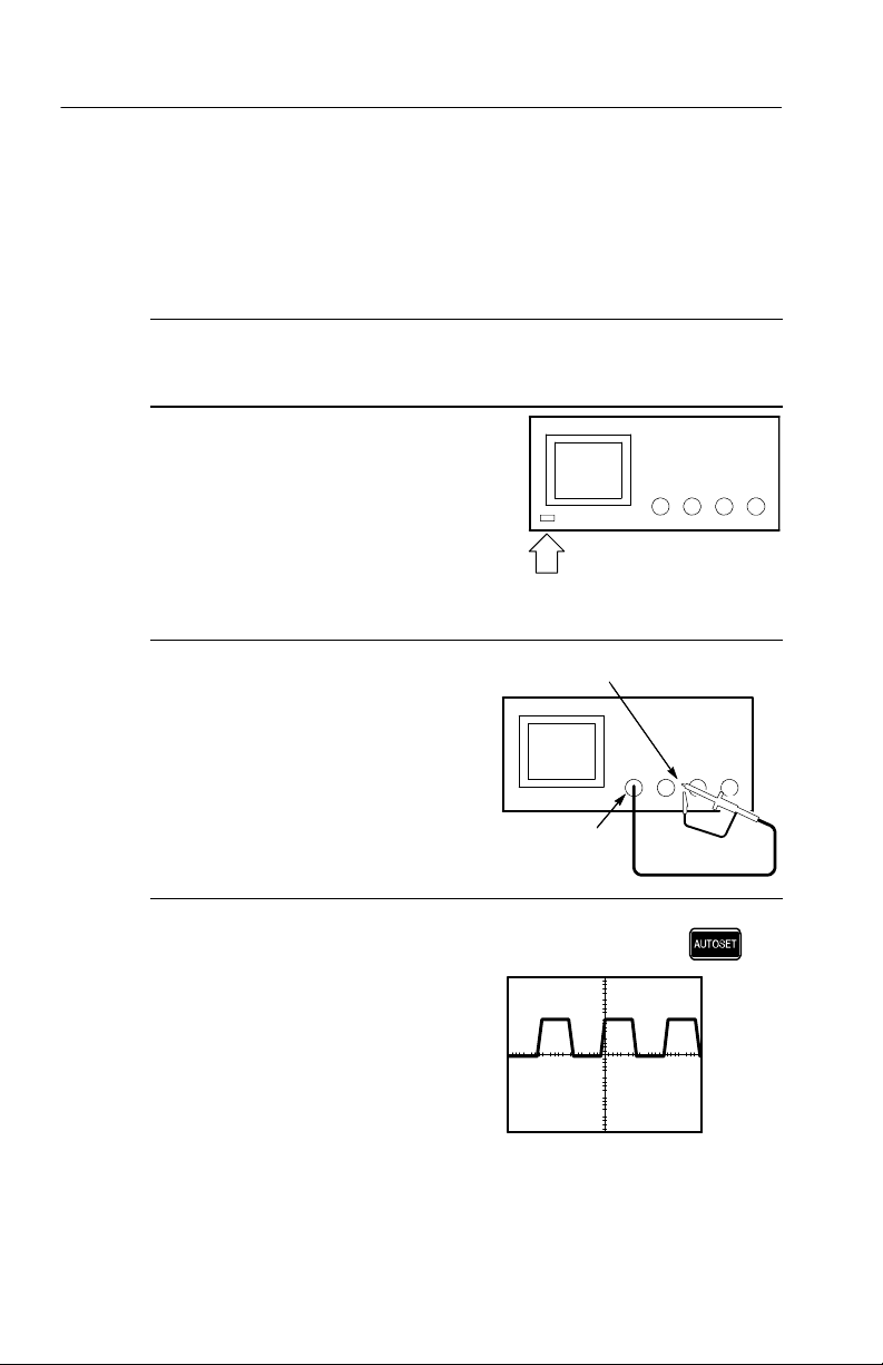
Functional Check
Perform this quick functional check to verify that your oscilloscope
is operating correctly.
1. Connect the oscilloscope power
2. Turn on the oscilloscope.
cable (refer to page 1--11).
Wait for the confirmation that
all self tests have passed.
3. Connect the oscilloscope probe
to channel 1. Attach the probe
tip and reference lead to the
PROBE COMP connectors.
4. Push the AUTOSET button.
You should see a square wave in
the display (approximately 5 V
at 1 kHz).
P ASSE
D
On/Standby
button
PROBE COMP
CH 1
1- 2
TDS3000B Series User Manual
Page 21
Getting Started
A
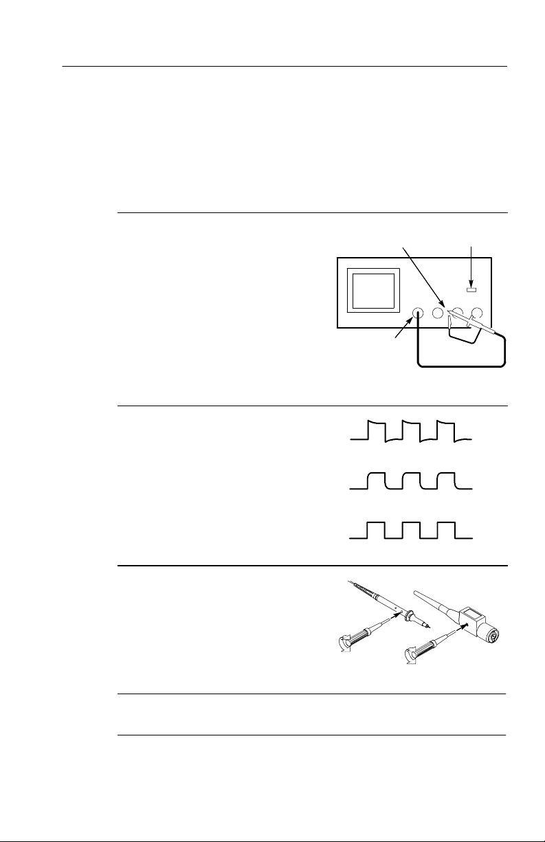
Probe Compensation
Perform this adjustment to match your probe to the input channel.
This should be done whenever you attach a passive probe for the first
time to any input channel.
1. Connect the oscilloscope probe
to channel 1. Attach the probe
tip and reference lead to the
PROBE COMP connectors,
then push AUTOSET.
If using the probe hook-tip,
ensure a proper connection by
firmly twisting the tip onto the
probe.
2. Check the shape of the displayed
waveform.
3. If necessary, adjust your probe.
Repeat as necessary.
PROBE COMP
CH 1
Overcompensated
Undercompensated
Compensated correctly
P3010 P6139A
L
UTOSET
button
NOTE.SeeAppendix D: Probe Basics for more information about the
probes provided with your oscilloscope.
TDS3000B Series User Manual
1- 3
Page 22

Getting Started
Signal Path Compensation (SPC)
The signal path compensation (SPC) routine optimizes the
oscilloscope signal path for maximum measurement accuracy. You
can run the routine anytime but you should always run the routine if
the ambient temperature changes by 10_ Cormore.
To compensate the signal path, do the following steps:
1. Disconnect any probes or cables from the channel input
2. Push the UTILITY button.
3. Push the System screen button to select Cal.
4. Push the Signal Path screen button.
5. Push OK Compensate Signal Path. This procedure takes several
NOTE. The signal path compensation does not include calibration to
the probe tip.
connectors.
minutes to complete.
1- 4
Adjusting the Oscilloscope Time and Date
To set your oscilloscope to the current date and time, do the
following steps:
1. Push the UTILITY button.
2. Push the System menu button to select Config.
3. Push the Set Date & Time menu button. Use the side menu
buttons to set the date and time values.
4. Push the OK Enter Date/Time menu button to set the instrument
date and time.
TDS3000B Series User Manual
Page 23

Product and Feature Description
The TDS3000B Series Digital Phosphor Oscilloscope family consists
of the models in the table below.
Model Bandwidth
TDS3012B (2 Ch), TDS3014B (4 Ch) 100 MHz 1.25 GS/s
TDS3024B (4 Ch) 200 MHz 2.5 GS/s
TDS3032B (2 Ch), TDS3034B (4 Ch) 300 MHz 2.5 GS/s
TDS3044B (4 Ch) 400 MHz 5GS/s
TDS3052B (2 Ch), TDS3054B (4 Ch) 500 MHz 5GS/s
TDS3064B (4 Ch) 600 MHz 5GS/s
Acquisition Features
WaveAlertt Waveform Anomaly Detection. Automatically detects
anomalous waveforms by comparing the current waveform to the
previous waveform. Sets how the oscilloscope responds: stop on
anomaly, beep on anomaly, and save anomalous waveform to disk.
Useful for capturing signal glitches and intermittent waveform
errors. See page 3--13.
Getting Started
Maximum
sample rate
Separate Digitizers. Ensure accurate timing measurements with
separate digitizers for each channel. Each digitizer can sample at up
to the maximum sample rate; acquisition on all channels is always
concurrent to provide full single-shot bandwidth on each channel.
TDS3000B Series User Manual
1- 5
Page 24

Getting Started
Normal Acquisition. Acquire 10,000 point waveforms to capture
horizontal detail and then use the zoom
detail. See page 3--12.
Fast Trigger Acquisition. Acquire up to 3,600 waveforms per second
(300 MHz -- 600 MHz models, 500 point mode) to see rapidly
changing signals or intermittent signal irregularities. See page 3--12.
Pretrigger. You can capture signals that occur before the trigger point.
You can position the trigger point at the beginning of the acquisition,
at the end, or at any location in between. See page 3--31.
Delay. You can also delay the acquisition so that it starts after the
trigger point. Use delay when you want to acquire the signal at a
specific time after the trigger point. See page 3--33.
Peak Detect. See pulses as narrow as 1 ns even at the slower time base
settings. Peak Detect helps you see noise and glitches in your signal.
Seepage3--9.
Signal Processing Features
Average. Apply averagi ng to your signal to remove uncorrelated noise
and improve measurement accuracy. See page 3 --10.
function to analyze the
1- 6
Envelope. Use envelope to capture and display the maximum
variation of a signal. See page 3--10.
Waveform Math. Use waveform math to add, subtract, multiply, or
divide waveforms. For example, you can use math to analyze
differential signals or calculate a power waveform. See page 3--84.
TDS3000B Series User Manual
Page 25

Getting Started
Display Features
Color LCD Display. Identify a nd differentiate waveforms easily with
color coding. Waveforms, readouts, and buttons are color matched to
increase productivity and reduce operating errors. See page 3--25.
Digital Phosphor. A Digital Phosphor Oscilloscope can clearly display
intensity modulation in your signals. The oscilloscope automatically
overlays subsequent acquisitions and then decays them to simulate
the writing and decay of the phosphor in an analog oscilloscope
CRT. This feature results in an intensity-graded waveform display
that shows the information contained in the intensity modulation.
Seepage3--5.
Signal Preview. Use the preview feature to optimize the control
settings when setting up a single-shot acquisition. As you adjust the
controls, the adjustments modify the current acquisition to show a
preview of how the next acquisition should appear. See page 3--8.
Measurement Features
Cursors. Use cursors to take simple voltage, time, and frequency
measurements. See page 3--16.
Automatic Measurements. Choose from a list of automatic waveform
measurements. You can customize the measurements by changing
reference levels or by adding measurement gating. See page 3--39.
XY Waveform Cursors. Use cursors to take measurements on XY
waveforms. See page 3--21.
TDS3000B Series User Manual
1- 7
Page 26

Getting Started
Trigger Features
Dual Triggers. Use the main (A) trigger system alone or add the B
trigger to capture more complex events. You can use the A and B
triggers together to set up a wait-for-time or wait-for-events trigger.
Seepage3--59.
Video Trigger. Trigger on video fields or lines to see a stable display of
standard video signals. See page 3--69.
Alternating Trigger. Sequentially use each active channel as a trigger
source, from the lowest-numbered active channel to the highe stnumbered active channel. See page 3--67.
External Triggering on Four-Channel Instruments. All models have an
external trigger input. Four-channel models have the external trigger
connector on the back of the instrument. Two-channel models have
the external trigger conenctor on the front panel.
Convenience Features
e*Scope™ Web-based Remote Control. Access your TDS3000B through
the Internet, from across a room to across the world. See page 3--88.
1- 8
Built-in Ethernet. Connect your TDS3000B Series oscilloscope to the
Internet using the built-in 10BaseT Ethernet port, for e*Scope access
or printing screen images to network printers. See page G--1.
Autoset. Use Autoset to quickly set up the vertical, horizontal, and
trigger controls for a usable display. See page 3--4.
Scope QuickMenu. Use the built-in Scope QuickMenu for simplified
oscilloscope operation. See page 1--29.
TDS3000B Series User Manual
Page 27

Getting Started
Single Sequence. One button sets the trigger parameters to the correct
settings for a single-shot acquisition (or single-sequence acquisition).
Seepage3--3.
Floppy Disk. Use the built-in floppy disk to store and recall wave-
forms and setups, as well as upgrade the oscilloscope firmware and
install new features. See page 3--52.
Probe Support. Use the standard probes or choose an optional probe
for a specific application. See page D--1 for information and
limitations.
Multilingual User Interface. On-screen menus and messages are in
11 languages. See page 3--71.
Optional Features
Application Modules. Install powerful application modules to add new
test and measurement features. See page C-- 2.
Communication Modules. Install a communication module to add
RS-232, GPIB, or VGA ports for remote programmability or
displaying the oscilloscope screen on a monitor. See page 1--18.
Battery Power. Install a rechargeable Lithium-Ion battery pack
(TDS3BATB) to use the oscilloscope without line power. See
page 1--12.
Plug-in Thermal Printer. Install instrument-powered thermal printer
TDS3PRT to print monochrome hard copy of your TDS3000B
screens. See page C--4.
TDS3000B Series User Manual
1- 9
Page 28
Getting Started
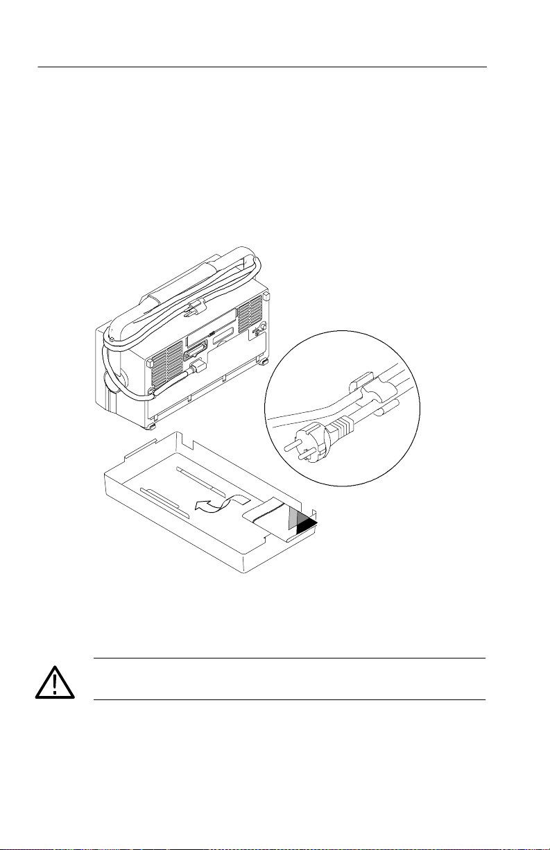
T ransporting the Oscilloscope
When transporting the oscilloscope, wrap the cord around the handle
as shown below. Use the supplied cord retainer if the power plug
does not have a molded-in retainer. The oscilloscope front cover has
a convenient place to store the Reference Manual .
1- 10
If you are not using a battery, use the accessory tray in the battery
compartment to store probes and other accessories.
CAUTION. To avoid damage to the disk drive, do not transport the
oscilloscope with a floppy disk in the disk drive.
TDS3000B Series User Manual
Page 29
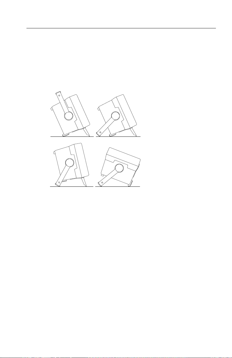
Operating Positions
Use the handle and feet to place the oscilloscope in a convenient
operating position.
Getting Started
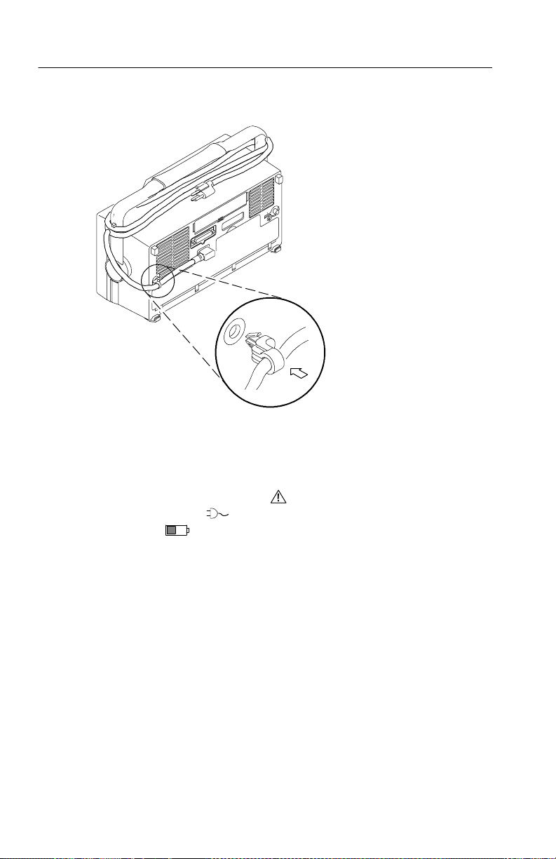
Connecting Power
To connect a power cord, do these steps:
1. Open the strain relief and slip it over the power cord.
2. Snap the strain relief into its hole in the rear panel of the
oscilloscope.
3. Connect the power cord to the power input connector.
You can operate the oscilloscope from a grounded mains supply with
line voltage between 90 V
47 Hz and 440 Hz. The oscilloscope is grounded through the power
cord. The line fuse is internal and is not user replaceable.
TDS3000B Series User Manual
and 250 VACand frequency between
AC
1- 11
Page 30
Getting Started
Using Battery Power
You can operate the oscilloscope continuously for approximately
three hours from the optional rechargeable TDS3BATB battery pack.
A triangle icon in the display (
a power-plug icon (
gauge icon (
oscilloscope turns off automatically when the battery runs low; the
screen may turn white a few minutes before the automatic shutdown.
) shows when the batte ry is in use,
) shows when line power is connected, and a
) shows the charge level in the battery. The
1- 12
Refer to the General Safety Summary for information about proper
battery disposal.
TDS3000B Series User Manual
Page 31
Getting Started
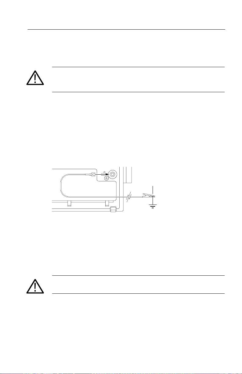
Operating Safely with Battery Power
WARNING. To avoid ele ctric shock, connect the rear-panel ground
terminal to earth ground when operating the instrument from battery
power.
For safe operation, the oscilloscope chassis should always remain at
earth ground potential. Without a connection between the chassis and
earth ground, you can receive a shock from exposed metal on the
chassis if you connect an input to a hazardous voltage (>30 V
>42 V
). Protection against this condition is provided when you
pk
RMS
,
attach the Tektronix-supplied grounding wire from the terminal on
the rear panel to earth ground. If you use a di fferent grounding wire,
it must be at least 18 gauge.
If you choose not to attach the grounding wire, you are not protected
against electric shock if you connect the oscilloscope to a hazardous
voltage. You can still use t he oscilloscope if you do not connect a
signal greater than 30 V
connector center, or the common lead. Ensure that all probe common
leads are connected to the same voltage. Also, do not connect a
grounded device, such as a printer or computer, to the oscilloscope.
WARNING. Hazardous voltages may exist in unexpected places due to
faulty circuitry in the device under test.
TDS3000B Series User Manual
(42 Vpk) to the probe tip, the BNC
RMS
1- 13
Page 32

Getting Started
Installing the Battery
To install the optional battery pack, do these steps:
1. Open the battery compartment door on the rear panel.
2. Remove the accessory tray.
Battery door
(Opened)
1- 14
3. Slide the battery into the compartment and press it in from both
sides until you hear the latches click.
4. Press on both sides of the battery compartment door to snap it
closed.
TDS3000B Series User Manual
Page 33

Getting Started
To remove the battery, do these steps:
1. Open the battery compartment door.
2. Raise the handles on each side of the battery and use them to pull
the battery out of the oscilloscope.
Maximizing Operating Time
To maximize the time that the oscilloscope can operate from a full
battery charge, consider doing these things:
H Reduce the display backlight intensity (see page 3--23)
H Disconnect unused active probes
H Only use passive probes
TDS3000B Series User Manual
1- 15
Page 34

Getting Started
Charging the Battery
The battery charges automatically when the oscilloscope is
connected to line power. You can also charge the battery with the
optional external charger (TDS3CHG).
Configuration Typical charging time
Battery charging in oscilloscope with
oscilloscope turned on or off
30 hours
Battery charging with TDS3CHG
external charger
5 hours
NOTE. Charge the battery before using it for the first time or after
prolonged storage.
1- 16
TDS3000B Series User Manual
Page 35

Installing an Application Module
CAUTION. To avoid damage to the oscilloscope or application
module, observe the ESD precautions described on page viii.
Optional application packages are available to extend the capability
of your oscilloscope. You can install up to four application modules
at one time. Application modules can go into the two slots with
windows in the upper right corner of the front panel. Two additional
slots are directly behind the two you can see.
Refer to the TDS3000 & TDS3000B Series Application Module
Installation Instructions that came with your application module for
instructions on installing and testing an application module.
NOTE. If you remove an application module, the features provided by
the application module become unavailable. You can reinstall the
module to restore the features.
Getting Started
TDS3000B Series User Manual
1- 17
Page 36

Getting Started
manualandth
e
TDS3000
&
Installing a Communication Module
CAUTION. To avoid damage to the oscilloscope or communication
module, observe the ESD precautions described on page viii.
To install one of the optional communications modules, do these
steps:
1. Turn the oscilloscope power off.
2. Press down on the latc hing tab to remove the blank cover.
3. Slide the communicati on module i nto the compartment until the
internal connectors are seated and the latching tab locks.
4. Turn power on. The communication module is now ready for
your use.
To remove a communication module, do these steps:
1. Turn the oscilloscope power off.
2. Press down on the latching tab and then use a small screwdriver
to alternately pry out the sides of the communication module.
3. Slide out the communication module and store it in an ESDshielded bag. Install the blank cover if no other communication
module is to be installed.
Communication module port For more information, see
GPIB Hard Copy on page 3--27 of this
manual and the TDS3000 &
RS-232
VGA Page A--9 in this manual
1- 18
TDS3000B Series Programmer
Manual
TDS3000B Series User Manual
Page 37

Latching tab
Front-Panel Menus and Controls
The front panel has buttons and controls for the functions you use
most often. The front panel has menus to access more specialized
functions.
Getting Started
Using the Menu System
To use the menu system, follow the steps shown on the next two
pages.
TDS3000B Series User Manual
1- 19
Page 38

Getting Started
1. Push a dark-colored front-panel menu button to display the menu
2. Push a bottom screen button to select a menu item. If a pop-up
you want to use.
MEASURE SAVE/RECALL QUICKMENU
UTILITYDISPLAYCURSOR
VERTICAL HORIZONTAL TRIGGER ACQUIRE
menu appears, continue to push the screen button to select an
item from the pop-up menu.
1- 20
TDS3000B Series User Manual
Page 39
Getting Started
3. Push a side screen button to choose a menu item. If the menu
item contains more than one choice, push the side screen button
again to make the choice.
4. Certain menu choices require you to set a numerical value to
complete the setup. Use the general purpose knob to adjust the
parameter value. Push the COARSE button to make larger
adjustments.
TDS3000B Series User Manual
SELECT
COARSE
VERTICAL
POSITION
1- 21
Page 40

Getting Started
Using the Menu Buttons
You can use the menu buttons to perform many functions in the
oscilloscope.
MEASURE SAVE/RECALL QUICKMENUSELECT
COARSE
21
4365
UTILIT YDISPLAYCURSOR
1. MEASURE. Performs automated measurements of waveforms.
2. CURSOR. Activates the cursors.
3. SAVE/RECALL. Saves and recalls setups and waveforms to
memory or a floppy disk.
4. DISPLAY. Changes the appearance of waveforms and the display
screen.
5. QUICKMENU. Activates QuickMenus such as the built-in Scope
QuickMenu.
6. UTILITY. Activates the system utility functions, such as
selecting a language.
1- 22
TDS3000B Series User Manual
Page 41
Getting Started
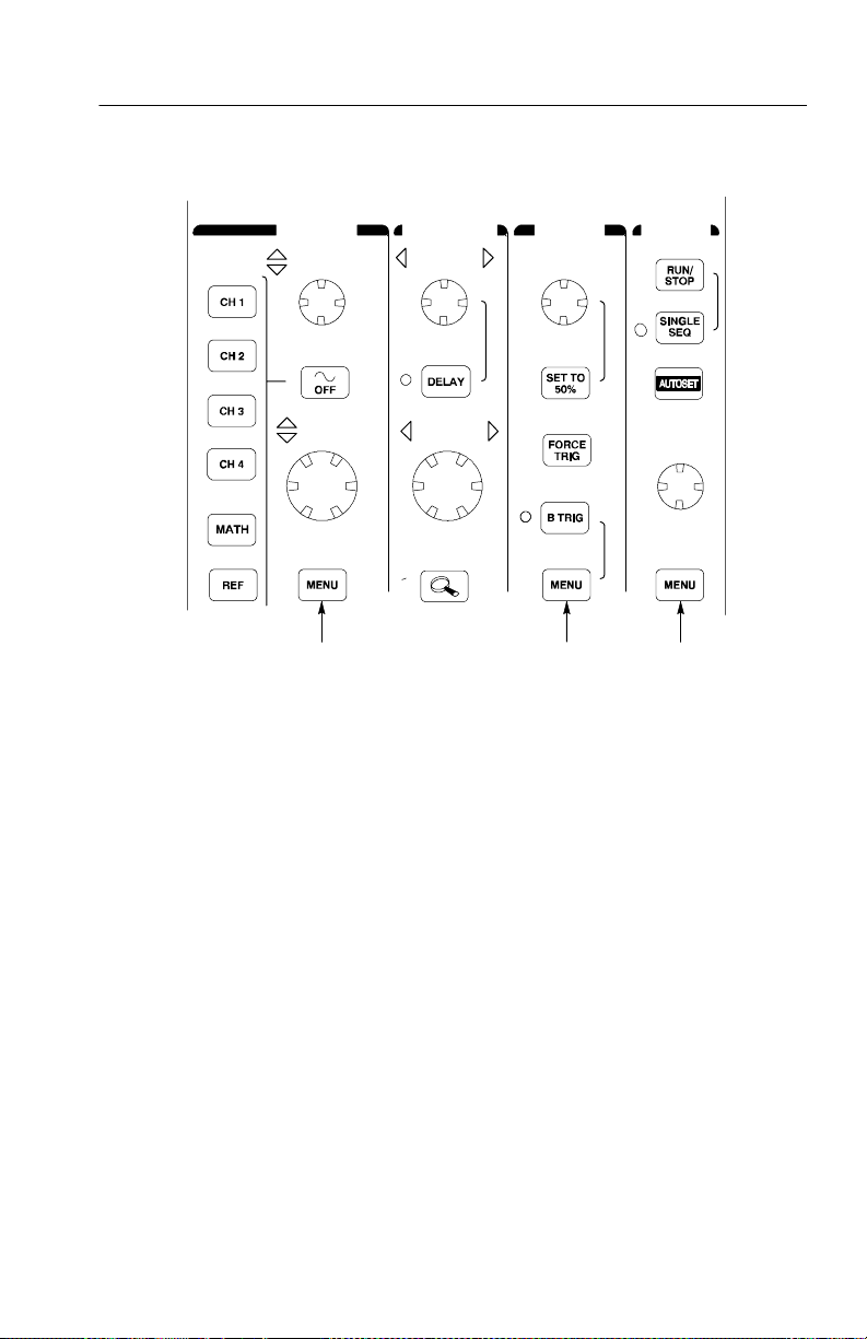
VERTICAL HORIZONTAL TRIGGER ACQUIRE
POSITION POSITION LEVEL
SCALE SCALE
WAVEFORM
INTENS ITY
987
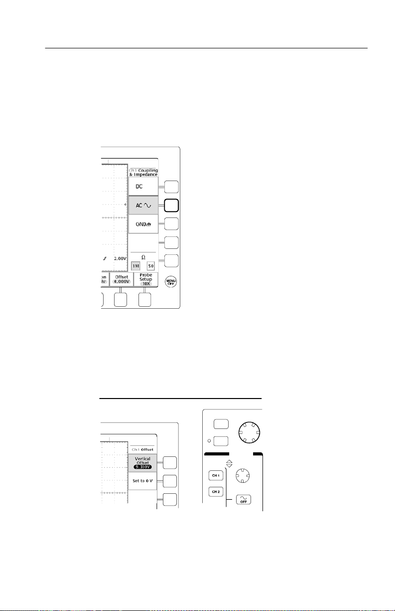
7. Vertical MENU. Adjusts the scale, position, and offset of
waveforms. Sets the input parameters.
8. Trigger MENU. Adjusts the trigger functions.
9. Acquire MENU. Sets the acquisition modes and horizontal
resolution, and resets the delay time.
TDS3000B Series User Manual
1- 23
Page 42
Getting Started
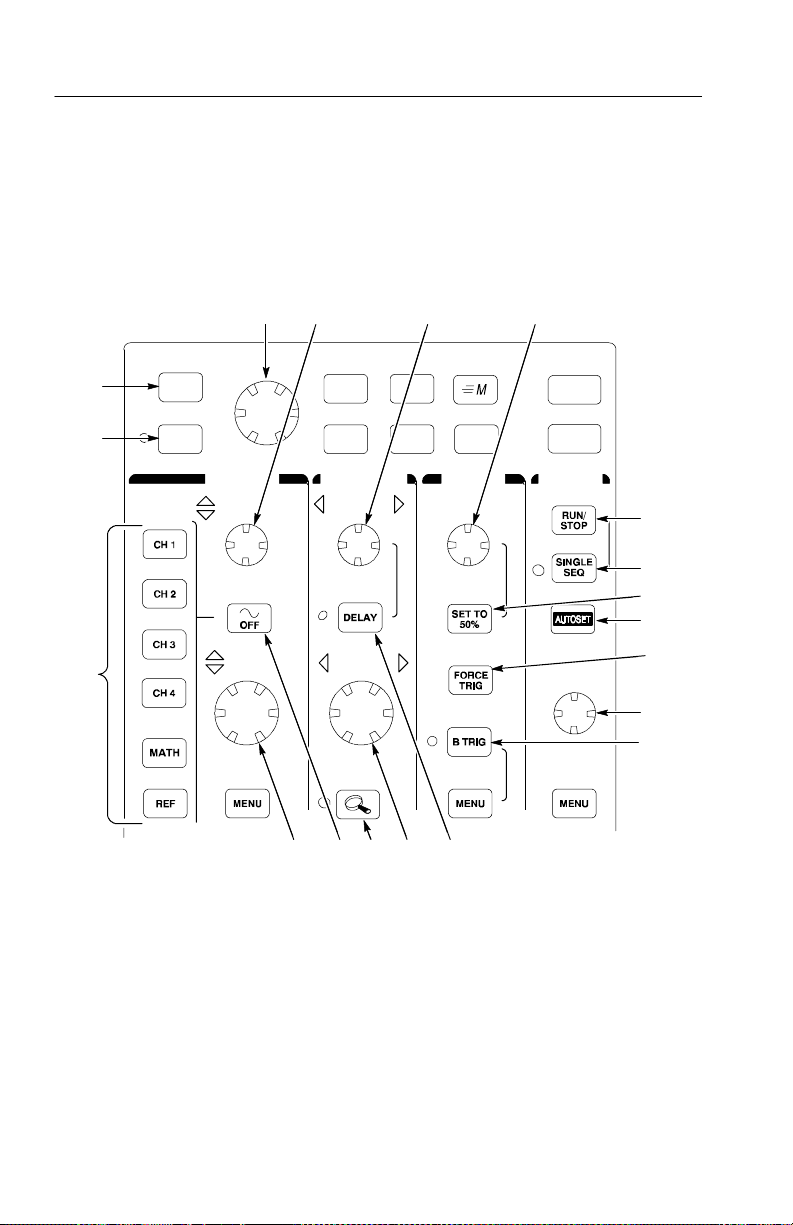
Using the Dedicated Controls
These dedicated buttons and controls generally control waveforms
and cursors without the use of menus.
SELECT MEASURE SAVE/RECALL QUICKMENU
2
COARSE UTILITYDISPLAYCURSOR
1
19
34 5 6
VERTICAL HORIZONTAL TRIGGER ACQUIRE
POSITION POSITION LEVEL
SCALE SCALE
WAVEFORM
INTENS ITY
7
8
9
10
11
1- 24
12
13
14151618 17
TDS3000B Series User Manual
Page 43

Getting Started
1. COARSE. Causes the general purpose knob and position knobs to
make adjustments more quickly.
2. SELECT. Toggles between the two cursors to select the active
cursor.
3. General purpose knob. Moves the cursors. Set s numerical
parameter values for some menu items. Push COARSE to make
adjustments quickly.
4. Vertical POSITION. Adjusts the vertical position of the selected
waveform. Push COARSE to make adjustments more quickly.
5. Horizontal POSITION. Adjusts the trigger point location relative
to the acquired waveforms. Push COARSE to make adjustments
quickly.
6. Trigger LEVEL. Adjusts the trigger level.
7. RUN/STOP. Stops and restarts acquisition.
8. SINGLE SEQ. Sets acquisition, display, and trigger parameters
for a single-shot (single-sequence) acquisition.
9. SET TO 50%. Sets the trigger level to the midpoint of the
waveform.
10. AUTOSET. Automatically sets the vertical, horizontal, and
trigger controls for a usable display.
11. FORCE TRIG. Forces an immediate trigger event.
12. WAVEFORM INTENSITY. Controls waveform intensity.
13. B TRIG. Activates the B trigger. Changes the trigger menu to set
the B-trigger parameters.
14. DELAY. Enables delayed acquisition relative to the trigger event.
Use horizontal POSITION to set the amount of delay.
TDS3000B Series User Manual
1- 25
Page 44

Getting Started
15. Horizontal SCALE. Adjusts the horizontal scale factor.
16. Horizontal zoom. Splits the screen and magnifies the current
17. Waveform OFF. Removes selected waveform from the display.
18. Vertical SCALE. Adjusts selected waveform vertical scale factor.
19. CH1, CH2, (CH3, CH4,) MATH. Displays a waveform and
acquisition horizontally.
chooses the selected waveform. REF shows the reference
waveform menu.
1- 26
20 2321 22
20. Hard copy. Initiates a hard copy using the port selected in the
Utility menu.
21. Power switch. Turns power to on or standby. Power-up time
varies from about 15 seconds to 45 seconds, dependi ng on the
oscilloscope internal calibration process.
22. Wrist-strap ground. Connect a wrist strap when working with
ESD-sensitive circuits. This connector is not a safety ground.
23. MENU OFF. Clears menu from the display.
TDS3000B Series User Manual
Page 45

Getting Started
Identifying Items in the Display
The following items may appear in the display; not all items are
visible at any given time. Some readouts move outside the graticule
area when menus are turned off.
2 3 4 5
1
13
12
1. Waveform baseline icons show t he z ero-volt level of the
waveforms (ignoring the effect of offset). The icon colors
correspond to the waveform colors.
2. Acquisition readout shows when acquisition is running, stopped,
or when acquisition preview is in effect.
11
6
7
8
9
10
3. Trigger position icon shows the trigger location in the waveforms.
4. Expansion point icon shows the point that the horizontal scale
expands and compresses around.
TDS3000B Series User Manual
1- 27
Page 46
Getting Started
5. Waveform record ic on shows the trigger location relative to the
6. Trigger status readout show trigger status.
7. Trigger level icon shows the trigger level on the waveform. The
8. Cursor and measurement readouts show results and m essages.
9. Trigger readouts show t he t rigger sources, slopes, and levels, and
10. Readout shows the delay setting or the trigger location within the
11. Horizontal readout shows the main or zoom time/division.
12. Auxiliary waveform readouts show the vertical and horizontal
13. Channel readouts show the channel scale factor, coupling, input
waveform record. The line color corresponds to the selected
waveform color.
icon color corresponds to the trigger source channel color.
position.
record.
scale factors of the math or reference waveforms.
resistance, bandwidth limit, and invert status.
1- 28
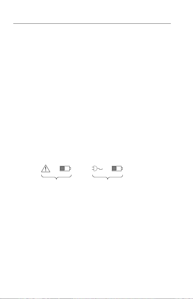
14 15
14. Triangle icon with the battery icon indicates a battery is installed
and battery power is in use. The battery icon shows the
approximate charge level of the battery. See page 1--13 for
important safety information.
15. Power-plug icon with the battery icon indicates a battery is
installed but line power is in use. The battery may be charging.
The battery icon shows the approximate charge level.
TDS3000B Series User Manual
Page 47

Getting Started
Using QuickMenus
The QuickMenu feature simplifies the use of the oscilloscope. When
you push the QUICKMENU button, a set of frequently used menu
functions show on the display. Then, push the screen buttons around
the display to operate the QuickMenu. See page 3--47 for general
instructions to operate QuickMenus.
Using the Scope QuickMenu. Scope is one type of QuickMenu that you
can use to control the basic oscilloscope functions. You can perform
many tasks without using the regular menu system. If you need to
use a function that is not contained in the Scope QuickMenu, push
the button you would normally push to access that function. For
example, if you want to add an automatic measurement, push the
MEASURE button to set up the measurement. Then, push the
QUICKMENU button to return to the Scope QuickMenu with the
measurement also in the display.
1 2
5 437
6
TDS3000B Series User Manual
1- 29
Page 48

Getting Started
1. Edge Trigger controls. Push these screen buttons to set trigger
2. Trigger controls if either B trigger or video trigger is selected.
3. Cursor control. Push this screen button to turn on cursors and
4. Acquisition controls. Push these screen buttons to set acquisition
5. Channel vertical controls. Push these screen buttons to set
6. Vertical controls if either the math waveform or a reference
7. Menu. Push this screen button to select a specific QuickMenu
parameters for edge trigger.
select the cursor type. Push the SELECT button to toggle
between the two cursors to select the active cursor. Use the
general purpose knob to move the active cursor.
parameters.
vertical controls for the selected channel. Use the CH1, CH2,
CH3, CH4, MATH, and REF buttons to select the channel you
want to control.
waveform is selected.
display if more than one is available.
1- 30
NOTE. Items in the Scope QuickMenu not mentioned above are also
contained in the regular display. Those items are described on
page 1--27.
Other QuickMenus. Some optional application packages include a
custom QuickMenu display. Those QuickMenus contain specific
features that are important for the application.
TDS3000B Series User Manual
Page 49

Front-Panel Connectors
1
1MΩ, 13pF ≤150 VRMS C ATl
PROBECOMP
CH 2CH 1
≈ 5V⊓
1MΩ, 13pF ≤150 VRMS C ATl
CH 4CH 3
Getting Started
50Ω
≤5VRMS
50Ω
≤5VRMS
2
1
1MΩ, 13pF ≤150 VRMS C ATl
CH 2CH 1
50Ω
≤5VRMS
2
PROBECOMP
≈ 5V⊓
1MΩ, 17pF ≤150 VRMS C ATl
EXT TRIG
3
1. PROBE COMP. Square wave signal source to compensate
probes.
2. CH 1, CH 2, (CH 3, CH 4). Channel inputs with TekProbe
interface.
3. EXT TRIG. External trigger input with TekProbe interface
(two-channel models only).
TDS3000B Series User Manual
1- 31
Page 50

Getting Started
Rear-Panel Connectors
1
8
2
3
4
5
6
7
+14.2 V DC
≤400 mA
1- 32
TDS3000B Series User Manual
Page 51

Getting Started
1. Power input. Attach to an AC power line with integral safety
ground.
2. Parallel printer port. Connect to a printer to make hard copies.
3. Communication Module compart ment. Install optional
communication modules or the thermal printer.
4. Ethernet port. Connects the oscilloscope to a 10Base-T local area
network. Available on all models.
5. External Trigger input (four-channel models only). See page A--6
for input specifications.
6. DC power output. Provides ~15 V DC power to accessories or to
the plug-in TDS3PRT thermal printer.
7. Ground terminal. Connect to earth ground when using battery
power. See page 1--13 for important safety informat ion.
8. CAL switch. For use by authorized service personnel only.
TDS3000B Series User Manual
1- 33
Page 52

Getting Started
Communication Module Connectors
12
TDS3GV
1. GPIB port. Connect to a controller for remote programmability.
2. RS-232 port. Connect to a controller or terminal for remote
programmability or printing.
3. VGA port. Connect to a VGA monitor to display the
screen image.
3
1- 34
TDS3000B Series User Manual
Page 53

Application Examples
Page 54

Page 55

Application Examples
This section presents five common oscilloscope applications:
H Taking simple measurements
H Analyzing signal detail
H Triggering on a video signal
H Capturing a single-shot signal
H Using the disk drive
Each application exa mple highlights different features of the
oscilloscope and gives you ideas about using the oscilloscope to
solve test problems.
TDS3000B Series User Manual
2- 1
Page 56

Application Examples
Taking Simple Measurements
You need to see a signal in a circuit, but you do not know the signal
amplitude or frequency. Connect the oscilloscope to quickly display
the signal and then measure its frequency and peak-to-peak
amplitude.
Ch 1
2- 2
Using Autoset
To quickly display a signal, do these steps:
1. Connect the channel 1 probe to the signal.
2. Push the AUTOSET button.
The oscilloscope sets vertical, horizontal, and trigger controls
automatically. You can manually adjust any of these controls if you
need to optimize the display of the waveform.
When you are using more than one channel, the autoset function sets
the vertical controls for each channel and uses the lowest-numbered
active channel to set the horizontal and trigger controls.
TDS3000B Series User Manual
Page 57

Application Examples
Selecting Automatic Measurements
The oscilloscope can take automatic measurements of most
displayed signals. To measure signal frequency and peak-to-peak
amplitude, do these steps:
1. Push the MEASURE button to see the measurement menu.
2. Push the CH 1 button and then push the Select Measurement for
Ch1 screen button.
3. Select the Frequency measurement.
4. Push the more screen button until you can select the Pk-Pk
measurement.
5. Push the MENU OFF button.
The measurements show on the screen and update as the signal
changes.
TDS3000B Series User Manual
2- 3
Page 58
Application Examples
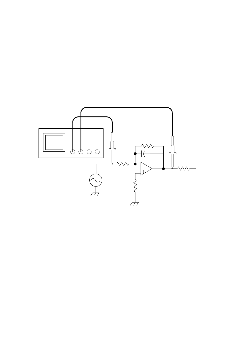
Measuring Two Signals
You are testing a piece of equipment and need to measure the gain of
its audio amplifier. You have an audio generator that can inject a test
signal at the amplifier input. Connect two oscilloscope channels to
the amplifier input and output as shown. Measure both signal levels
and use these measurements to calculate the gain.
Ch 1 Ch 2
2- 4
To display the signals connected to channels 1 and 2, do these steps:
1. Push the CH 1 and CH 2 buttons to activate both channels.
2. Push the AUTOSET button.
TDS3000B Series User Manual
Page 59
Application Examples
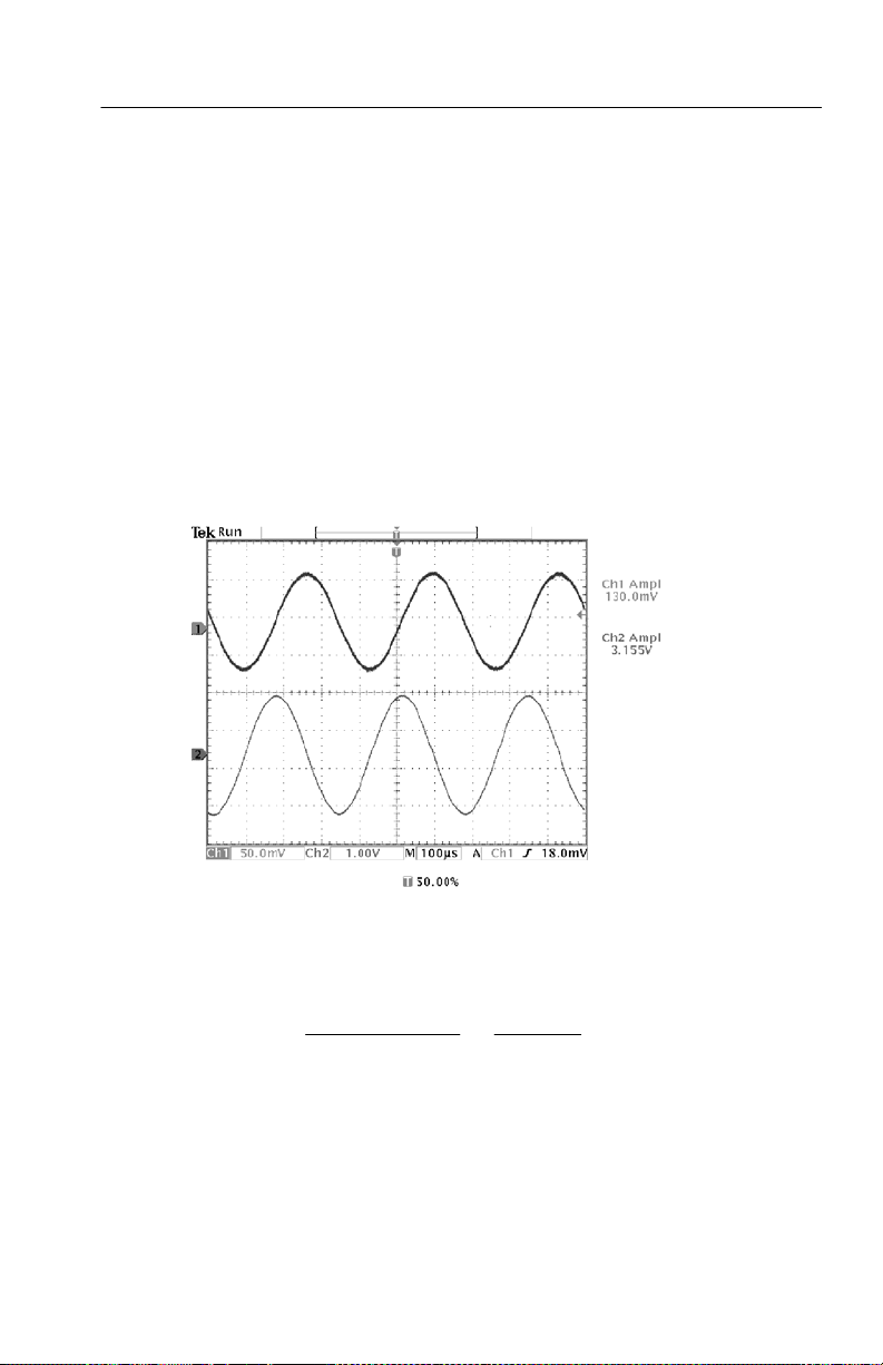
To select measurements for the two channels, do these steps:
1. Push the MEASURE button to see the measurement menu.
2. Push the CH 1 button and then push the Select Measurement for
Ch1 screen button.
3. Select the Amplitude measurement.
4. Push the CH 2 button and then push the Select Measurement for
Ch2 screen button.
5. Select the Amplitude measurement.
6. Calculate the amplifier gain using the following equations:
Gain =
Gain (dB) = 20 × log(24.27) = 27.7 dB
TDS3000B Series User Manual
output amplitude
input amplitude
3.155 V
=
130.0 mV
= 24.27
2- 5
Page 60

Application Examples
Customizing Your Measurements
In this example you want to verify that the incoming signal to a
piece of digital equipment meets its specifications. Specifically, the
transition time from a low logic level (0.8 V) to a high logic level
(2.0 V) must be 10 ns or less.
2.0 V
0.8 V
To select the rise time measurement, do these steps:
1. Push the MEASURE button to see the measurement menu.
2. Push the CH 1 button and then the Select Measurement for Ch1
screen button.
≤ 10 ns
2- 6
3. Select the Rise Time measurement.
Rise time is typically measured between the 10% and 90% amplitude
levels of a signal; these are the default reference levels the
oscilloscope uses for rise time measurements. However, in this
example you need to measure the time the signal takes to pass
between the 0.8 V and 2.0 V levels.
You can customize the rise time measurement to measure the signal
transition time between any two reference levels. You can set each of
those reference levels to a specific percent of the signal amplitude or
to a specific level in vertical units (such as volts or amperes).
TDS3000B Series User Manual
Page 61
Application Examples
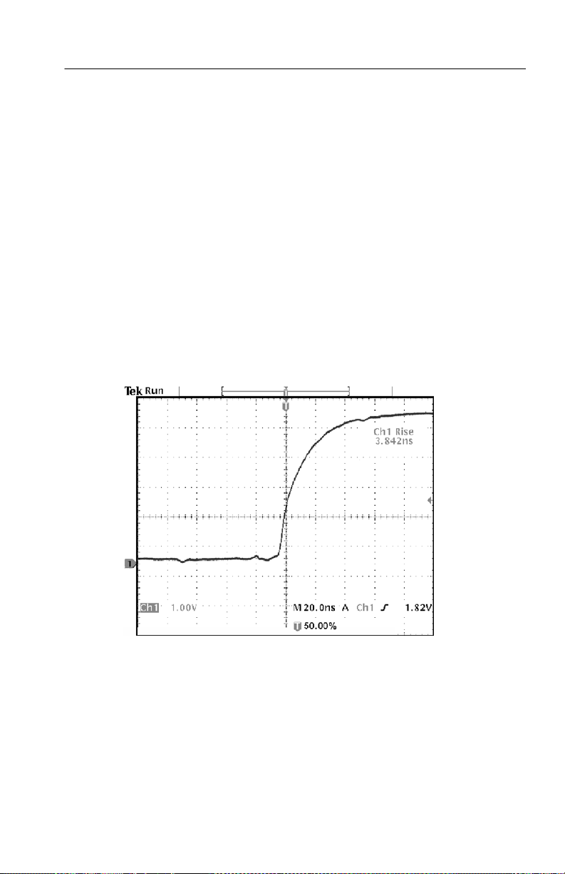
Setting Reference Levels. To set the reference levels to specific
voltages, do these steps:
1. Push the Reference Levels screen button.
2. Push the Set Levels in screen button to select units.
3. Push the High Ref screen button.
4. Use the general purpose knob to sel ect 2.0 V.
5. Push the Low Ref screen button.
6. Use the general purpose knob to sel ect 800 mV.
The measurement verifies that the transition time (3.842 ns) meets
the specification (≤ 10 ns).
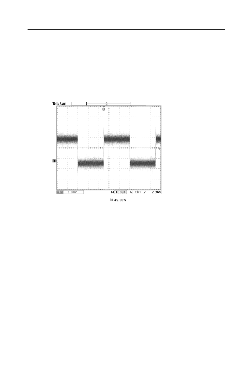
Measuring Specific Events. Next you want to see the pulses in the
incoming digital signal, but the pulse widths vary so it is hard to
establish a stable trigger. To look at a snapshot of the digital signal,
do this step:
1. Push the SINGLE SEQ button to capture a single acquisition.
TDS3000B Series User Manual
2- 7
Page 62
Application Examples
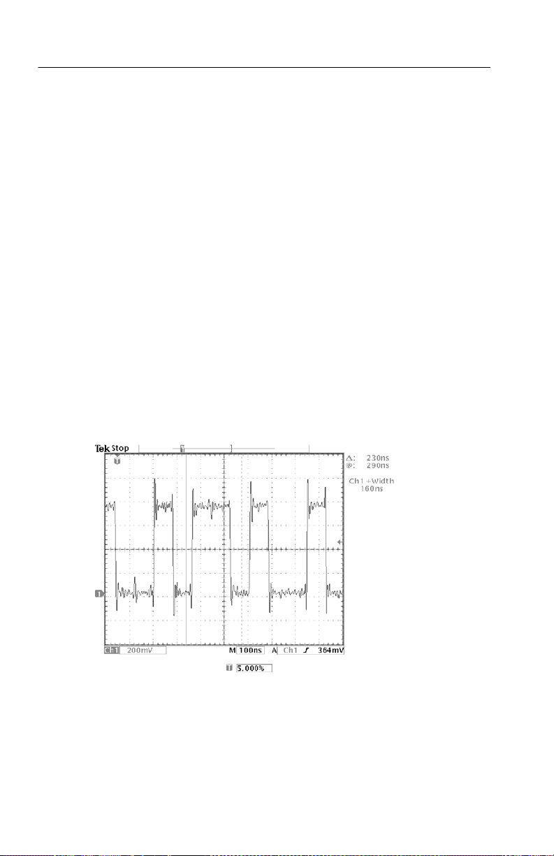
Now you want to measure the width of each displayed pulse. You
can use measurement gating to select a specific pulse to measure. To
measure the second pulse, for example, do these steps:
1. Push the MEASURE button.
2. Push the CH 1 button and then push the Select Measurement for
Ch1 screen button.
3. Select the Positive Width measurement.
4. Push the Gating screen button.
5. Select Gate With V Bar Cursors to choose measurement gating
using cursors.
6. Place one cursor to the left and one cursor to the right of the
second pulse.
The oscilloscope shows the width measurement (160 ns) for the
second pulse.
2- 8
TDS3000B Series User Manual
Page 63
Analyzing Signal Detail
You have a noisy signal displayed on the oscilloscope and you need
to know more about it. You suspect that the signal contains much
more detail than you can now see in the display.
Application Examples
TDS3000B Series User Manual
2- 9
Page 64
Application Examples
Looking at a Noisy Signal
The signal appears noisy and you suspect that noise is causing
problems in your circuit. To better analyze the noise, do these steps:
1. Push the acquire MENU button.
2. Select the Peak Detect acquisition mode.
3. Increase the WAVEFORM INTENSITY control to see the noise
more easily.
Peak detect emphasizes noise spikes and glitches in your signal as
narrow as 1 ns, even when the time base is set to a slow setting.
2- 10
Refer to page 3--9 for more information about peak-detect and the
other acquisition modes.
TDS3000B Series User Manual
Page 65

Application Examples
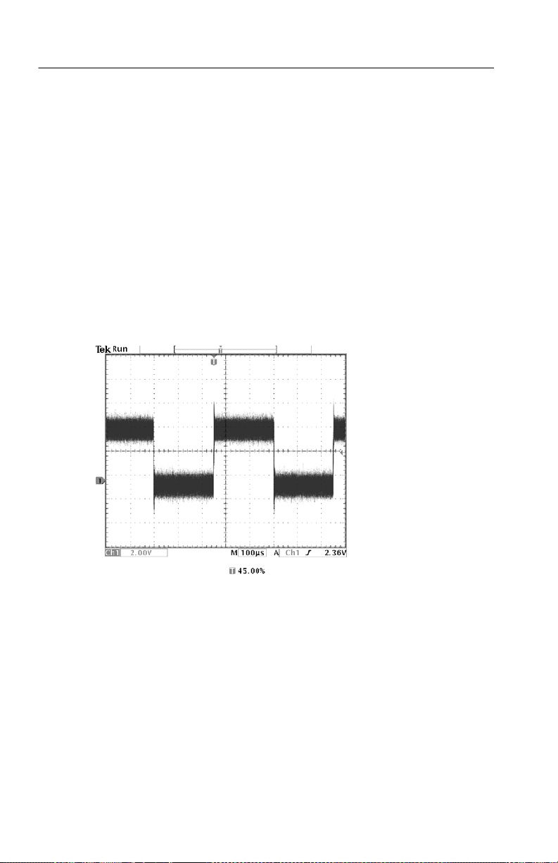
Separating the Signal from Noise
Now you want to anal yze the signal shape and ignore the noise. To
reduce random noise in the oscilloscope display, do these steps:
1. Push the acquire MENU button.
2. Push the Mode bottom button.
3. Select the Average acquisition mode.
Averaging reduces random noise and makes it easier to see detail in
a signal. In the example below, a ring shows on the rising and falling
edges of the signal when the noise is removed.
TDS3000B Series User Manual
2- 11
Page 66
Application Examples
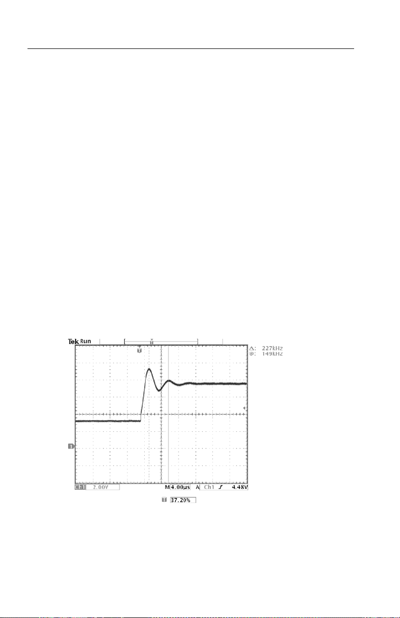
Taking Cursor Measurements
You can use the cursors to take quick measurements on a waveform.
To measure the ring frequency at the rising edge of the signal, do
these steps:
1. Push the CURSOR button.
2. Push the Function screen button.
3. Select V Bars cursors.
4. Push the V Bar Units screen button.
5. Select 1/seconds (Hz).
6. Place one cursor on the first peak of the ring using the general
purpose knob.
7. Push the SELECT button.
8. Place the other cursor on the next peak of the ring.
The cursor Δ readout shows the measured ring frequency is 227 kHz.
2- 12
TDS3000B Series User Manual
Page 67

Application Examples
Using Delay
You are analyzing a pulse waveform and use the + Width measurement to measure the waveform pulse width. You notice that the
measurement is not stable, which implies that there is jitter in the
pulse width.
To use delay to see the jitter, do these steps:
1. Push the DELAY button.
2. Adjust the horizontal POSITION control to set the delay close to
to the nominal pulse width (210 ms). Push the COARSE button to
make delay adjustments more quickly. Push COARSE again to
fine tune the delay time.
The falling edge of the pulse is now near the center of the screen.
When delay is on, the horizontal expansion point separates from the
trigger point and remains in the center of the screen.
TDS3000B Series User Manual
2- 13
Page 68

Application Examples
3. Adjust the horizontal SCALE to a faster time base setting and
increase the WAVEFORM INTENSITY to see the jitter in the
pulse width.
2- 14
NOTE. You can toggle the delay func tion on and off to view signal
details at two different areas of interest.
TDS3000B Series User Manual
Page 69

Application Examples
Measuring Jitter
To measure the peak-to-peak jitter, do these steps:
1. Push the CURSOR button.
2. Push the Function screen button.
3. Select the V Bars cursors.
4. Push the Bring Both Cursors On Screen screen button to
quickly locate the cursors.
5. Place one cursor at the first falling edge and place the other
cursor at the last falling edge.
6. Read the peak-to-peak jitter in the Δ readout (1.40 ms).
You can also measure the minimum and maximum pulse widths.
When you select the first cursor, the @ readout displays the
minimum pulse width (210 ms). When you select the second cursor,
the @ readout displays the maximum pulse width (211 ms).
TDS3000B Series User Manual
2- 15
Page 70
Application Examples
Triggering on a Video Signal
You are testing the video circuit in a piece of medical equipment and
need to display the video output signal. The video output is an NTSC
standard signal. Use the video trigger to obtain a stable display.
Ch 1
2- 16
To trigger on the video fields, do these steps:
1. Push the trigger MENU button.
2. Push the Type screen button to select Video.
3. Push the Standard screen button to select 525/NTSC.
TDS3000B Series User Manual
Page 71

Application Examples
4. Push the Trigger On screen button.
5. Select Odd.
6. Adjust the horizontal SCALE to see a complete field across the
screen.
7. Push the acquire MENU button.
8. Push the Resolution screen button.
9. Select Normal acquisition resolution.
Normal acquisition resolution is the best choice to acquire a video
field signal because the signal contains a great amount of horizontal
detail.
If the signal had been noninterlaced, you could c hoose to trigger on
All Fields.
TDS3000B Series User Manual
2- 17
Page 72

Application Examples
Triggering on Lines. You can also look at the video lines in the field.
To trigger on the lines, do these steps:
1. Push the Trigger On screen button.
2. Select All Lines.
3. Adjust the horizontal SCALE to see a complete video line across
the screen.
2- 18
NOTE. The optional TDS3VID and TDS3SDI application modules
add new video functions such as a video QuickMenu, video Autoset,
trigger on custom scan rates, trigger on specific video lines,
vectorscope (vectorscope supports component video only), video
picture, trigger on analog HDTV signals, and view 601 digital video
signals (TSD3SDI only).
TDS3000B Series User Manual
Page 73

Application Examples
Looking at Modulation. A dedicated video waveform monitor clearly
shows the modulation in a video signal. To see a similar modulation
display on the oscilloscope screen, do these steps:
1. Start with triggered display of the video lines.
2. Push the acquire MENU button.
3. Push the Resolution screen button.
4. Select Fast Trigger acquisition resolution.
5. Adjust the WAVEFORM INTENSITY control for the amount of
modulation you want to see.
The oscilloscope now shows signal modulation in shades of intensity
and appears similar to the display of a video waveform monitor or an
analog oscilloscope. Fast trigger acquisition resolution is the best
choice to acquire a video line signal with a rapidly changing shape.
TDS3000B Series User Manual
2- 19
Page 74
Application Examples
Capturing a Single-Shot Signal
The reliability of a reed relay in a piece of equipment has been poor
and you need to investigate the problem. You suspect that the relay
contacts arc when the relay opens. The fastest you can open and
close the relay is about once per minute so you need to capture the
voltage across the relay as a single-shot acquisition.
To set up for a single-shot acquisition, do these steps:
1. Adjust the vertical SCALE and horizontal SCALE to appropriate
ranges for the signal you expect to see.
2. Push the acquire MENU button.
3. Push the Resolution screen button.
4. Select Normal acquisition resolution.
5. Push the SINGLE SEQ (single sequence) button.
2- 20
The SINGLE SEQ button sets trigger parameters to the correct
settings for a single-shot acquisition.
TDS3000B Series User Manual
Page 75
Application Examples
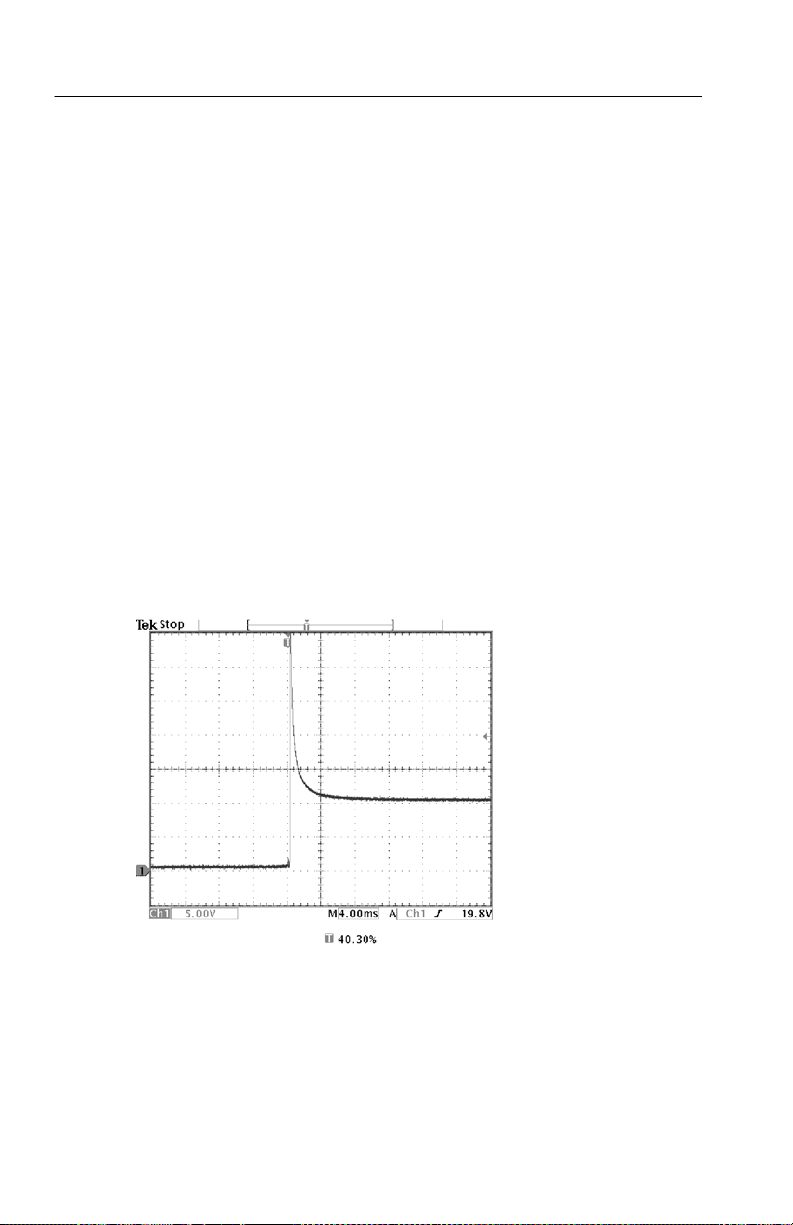
Optimizing the Acquisition
The initial acquisition shows the relay contact beginning to open at
the trigger point. This is followed by a large spikes that indicate
contact bounce and inductance in the circuit. The inductance can
cause contact arcing and premature relay failure.
Before you take the next acquisition, you can adjust the vertical and
horizontal controls to give you a preview of how the next acquisition
might appear. As you adjust these controls, the current acquisition is
repositioned, expanded, or compressed. This preview is useful to
optimize the settings before the next single-shot event is captured.
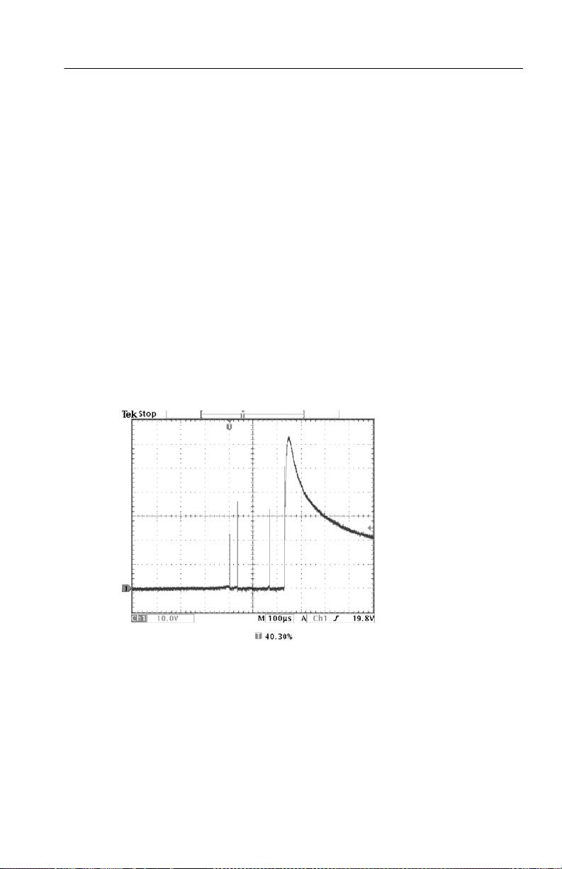
When next acquisition is captured with the new vertical and
horizontal settings, you can see more detail about the relay contact
opening. You can now see that t he contact bounces several times as
it opens.
TDS3000B Series User Manual
2- 21
Page 76

Application Examples
Using the Horizontal Zoom Function
If you want to take a close look at a particular spot on the acquired
waveform, use the horizontal zoom function. To look closely at the
point where the relay contact first begins to open, do these steps:
1. Push the zoom button
2. Use the horizontal POSITION to place the expansion point close
to where the relay contact begins to open.
3. Adjust the horizontal SCALE to magnify the waveform around
the expansion point.
The ragged waveform and the inductive load in the circuit suggest
that the relay contact may be arcing as it opens.
.
2- 22
The zoom function works equally well when acquisition is running
or is stopped. Horizontal position and scale changes affect only the
display, not the next acquisition.
TDS3000B Series User Manual
Page 77
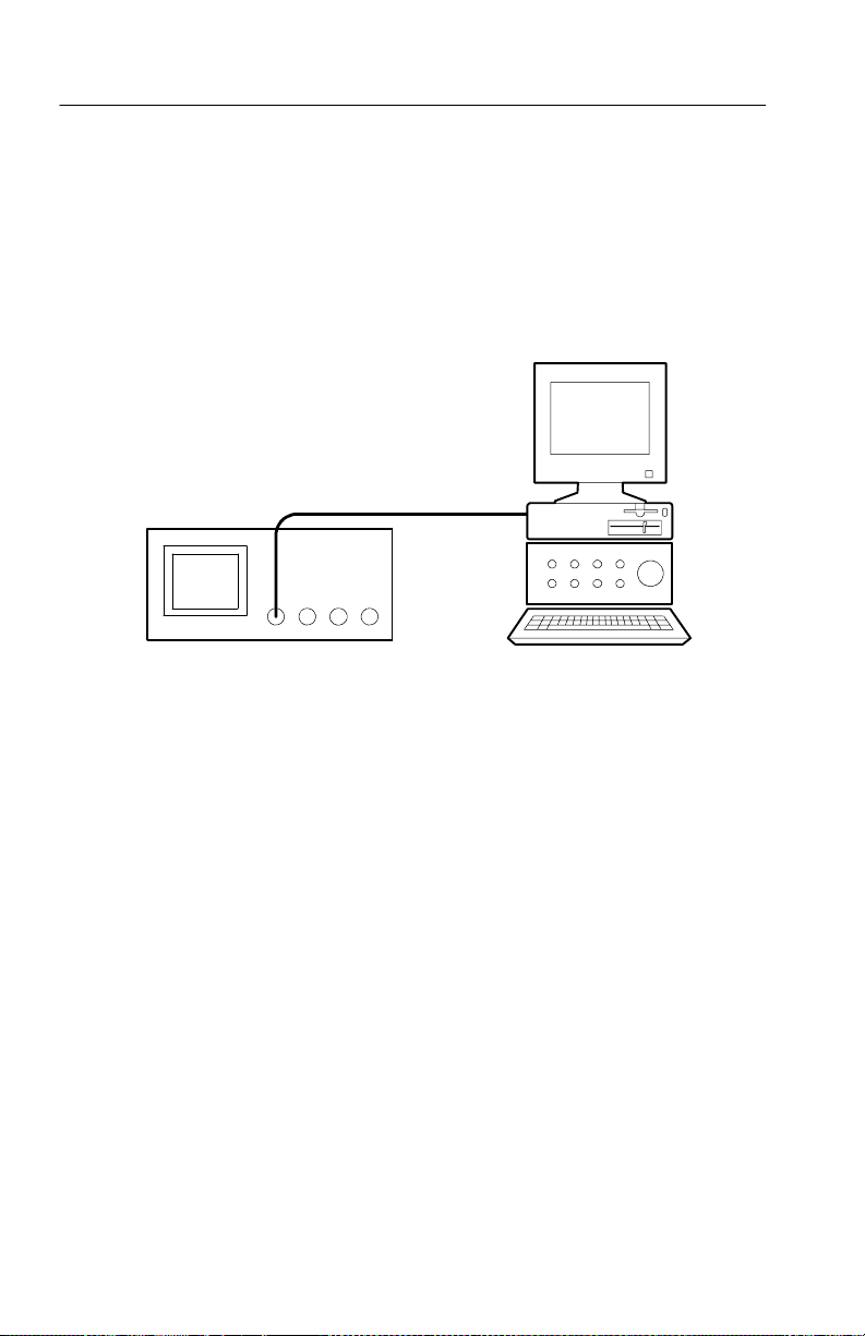
Saving Data to the Floppy Disk Drive
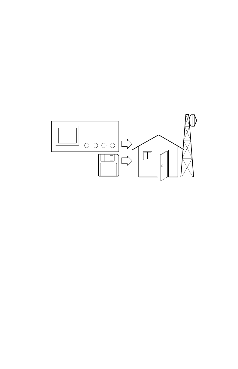
You need to do some work inside a remote site. You expect to use
the oscilloscope to look at signal waveforms and then bring
waveform information back to the office to complete a report and
perform additional analysis. To do this, take along an IBM-compatible floppy disk.
When you need to capture screen images, it may be most convenient
to first save them to disk. Once on the disk, you can load the screen
images into a PC, print hard copies with a printer attached to the
oscilloscope or your PC, or import the screen images into desktop
publishing software to produce a report.
Application Examples
Remote site
You can also save waveform data on the disk. From the disk, you can
recall waveforms to the oscilloscope display or you can import the
data into spreadsheet and Mathcad software to perform additional
analysis.
If you have oscilloscope setups that you want to use again, you also
can store them on the disk. See Save/Recall on page 3--48 for more
information on this capability. For information about remote control
and network printing accessories, see Appendix C: Accessories.
TDS3000B Series User Manual
2- 23
Page 78

Application Examples
Saving Screen Images
While working at the remote site you discover a control signal that
you want to capture periodically to show its long-term variation. You
want to include these waveforms in a report you are preparing back
at the office.
Your desktop publishing software can import BMP graphics, so you
decide to use this format for the screen images. To setup this
configuration, do these steps:
1. Insert a floppy disk into the disk drive.
2. Push the UTILITY button.
3. Push the System screen button to select Hard Copy.
4. Push the Format screen button.
5. Select BMP Windows mono image file format (you may need
to push the -- m o r e -- screen button several times before you see
this choice).
6. Push the Port screen button.
2- 24
7. Select File to send hard copies to disk.
8. Push the hard copy button
to save the image.
The oscilloscope reads the disk directory and displays its contents.
Naming Files. It is good practice to give disk files descriptive names
so you can recognize them when you get back to the office. You will
be saving images of the control signal so you decide CNTRL is a
logical target file name to use.
TDS3000B Series User Manual
Page 79
Application Examples
The oscilloscope can append an automatic sequence number to the
target file name. This feature is convenient because you want to
capture a screen image of the same control signal every five minutes.
To set up the target file name and automatic sequenc e, do these
steps:
1. Push the File Utilities screen button.
2. Use the general purpose knob to highlight the file
TEK?????.BMP.
3. Select the Rename screen button.
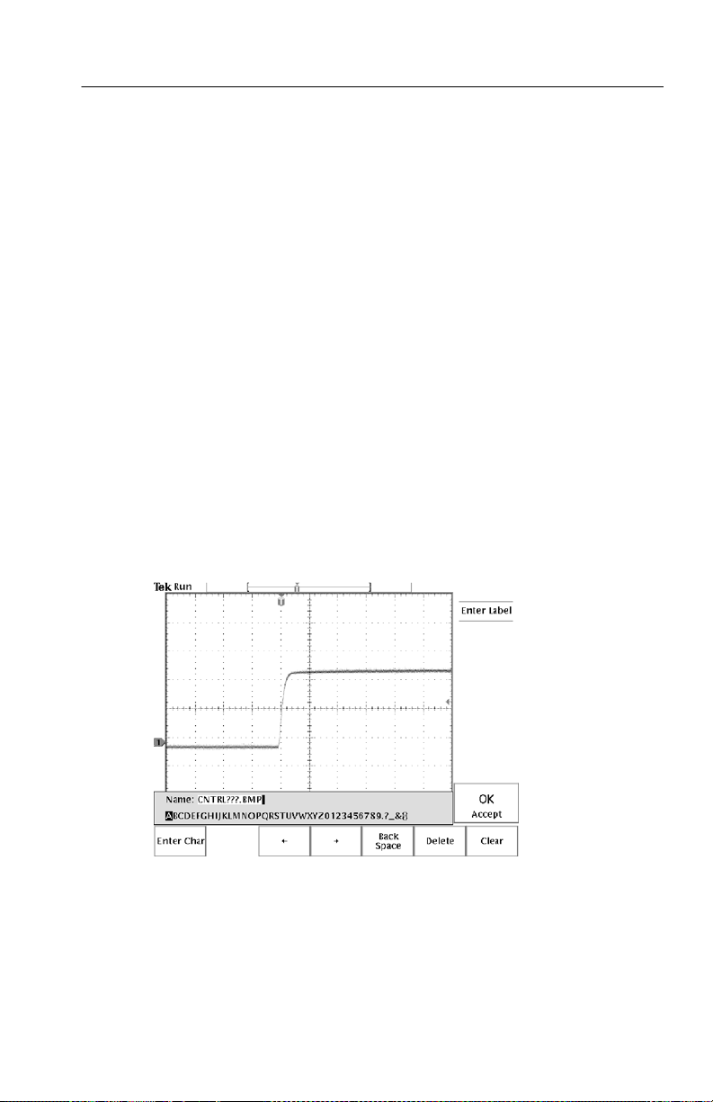
4. Use the screen buttons to clear the existing file name and enter
the new file name CNTRL???.BMP. The question marks are
placeholders for an automatic number sequence from 000 to 999.
5. Push the OK Accept screen button to setup the target base file
name.
6. Push MENU OFF to remove the file list from the display.
TDS3000B Series User Manual
2- 25
Page 80

Application Examples
Running the Test. To capture the control signal every few minutes, do
these steps:
1. Display the signal, measurements, and menus as you want them
to appear in the screen images.
2. Push the hardcopy button
.
3. Repeat step 2 every few minutes until you are finished with the
test.
4. When you are finished, push UTILITY to see the list of
sequential files that have been saved.
The files are labeled with their sequential names as well as the time
and date each was created. You can save up to four BMP images or
approximately 35 TIFF images on a single 1.44 MB floppy disk. You
can also enable file compression (UTILITY > System: Hard Copy
> Options) to compress files in zip format so that more files can fit
on a floppy disk.
2- 26
TDS3000B Series User Manual
Page 81
Application Examples
Saving Waveform Data
You find another signal that you want to analyze with a spreadsheet
program back at the office. To save the waveform data on a disk, do
these steps:
1. Display the signal on the oscilloscope screen.
2. Push the SAVE/RECALL button.
3. Push the Save Wfm screen button.
4. Select To File.
5. Select Spreadsheet File Format. The default target file,
TEK?????.CSV, is now automatically highlighted.
6. Push the Save To Selected File screen button to save the
waveform.
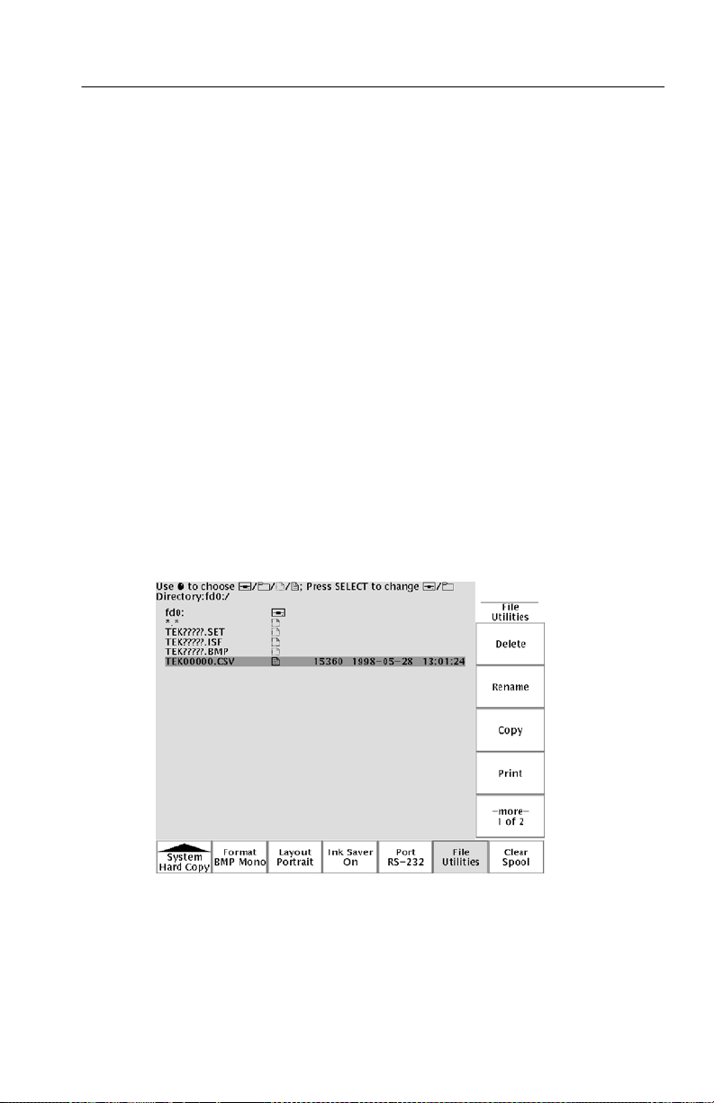
7. Push the File Utilities screen button to see the saved waveform
file TEK00000.CSV in the disk directory.
TDS3000B Series User Manual
2- 27
Page 82

Application Examples
2- 28
TDS3000B Series User Manual
Page 83

Reference
Page 84

Page 85

Introduction to Reference
This chapter contains detailed information about the operation of the
oscilloscope. The topics in this chapter are arranged by front-panel
button or control group name.
Reference topic Page
Acquire 3--2
Cursor 3--16
Display 3--23
Hard copy 3--27
Horizontal controls 3--31
Measure 3--39
QuickMenu 3--47
Save/Recall 3--48
Trigger controls 3--58
Utility 3--70
Vertical controls 3--80
e*Scope 3--88
TDS3000B Series User Manual
3- 1
Page 86

Acquisition Controls
Acquisition Controls
Run/Stop Button
Push the RUN/STOP button to stop and start waveform ac quisition.
Also push RUN/STOP when you want to resume cont inuous
acquisition after a single-sequence acquisition. Readout in the top
left corner of the display shows the status of the acquisition.
Acquisition status readout Description
Run: Acquisition is running.
Roll: A roll-mode acquisition is running.
Stop: Acquisition is stopped.
PreVu: Previewing; waiting for trigger.
While acquisition is running or stopped, you can use these controls
to examine the waveforms:
3- 2
H Channel buttons to select a channel
H Zoom button
magnify waveforms (does not affect the actual time base or
trigger position settings)
H WAVEFORM INTENSITY to adjust gray-scale level
H CURSOR button to activate cursors to measure waveforms
H MEASURE button to select automatic measurements of
waveforms
H Hard copy button
While acquisition is stopped, you can change the vertical and
horizontal controls to use in the next acquisition. See page 3--8 for
more information about this function.
with horizontal POSITION and SCALE to
to print a hard copy
TDS3000B Series User Manual
Page 87

Acquisition Controls
Single Sequence Button
Push the SINGLE SEQ button to execute a single-shot acquisition.
The function of the SINGLE SEQ button depends on the acquisition
mode.
Acquisition mode SINGLE SEQ function
Sample or Peak Detect One acquisition of each displayed
channel is acquired, concurrently
Envelope N or Average N N acquisitions of each displayed
channel are acquired (N is user
adjustable with the general purpose
knob)
When you push the SINGLE SEQ button, the oscilloscope does the
following things:
H The trigger mode is set to Normal
H The trigger system arms and the light next to the SINGLE SEQ
button turns on
After the single-sequence acquisition is complete, acquisition stops
and the light next to the SINGLE SEQ button turns off.
Push the SINGLE SEQ button again to acquire a new sequence, or
push the RUN/STOP button to restart continuous acquisition.
TDS3000B Series User Manual
3- 3
Page 88

Acquisition Controls
Autoset Button
Push the AUTOSET button to automatically adjust the vertical,
horizontal, and trigger controls for a usable display. You can
manually adjust any of these controls if you need to optimize the
display.
When you are using more than one channel, the autoset function sets
the vertical scale for each channel and positions the channels to
prevent overlapping. The autoset function selects the lowest-numbered channel in use and then uses that channel to set the horizontal
and trigger controls.
The autoset function also changes the following oscilloscope
settings:
H Acquisition mode is set to Sample
H Bandwidth limits are set to Full
H Zoom is turned off
H Trigger is set to Auto mode and minimum holdoff
H Trigger is set to Edge type, DC coupling, and rising slope
3- 4
H B trigger is turned off
H XY display format is turned off
H Channel 1 is turned on and selected if no active channels are
in use
If you push the AUTOSET button by accident, you can undo it with
these steps:
1. Push the Acquire MENU button.
2. Push the Autoset screen button and then push the Undo Autoset
screen button.
TDS3000B Series User Manual
Page 89

Acquisition Controls
Waveform Intensity
The WAVEFORM INTENSITY adjusts the intensity of the
waveforms in the display.
The term Digital Phosphor represents the way this control simulates
the intensity control of an analog oscilloscope. At maximum
intensity, a ll waveform points are displayed at full brightness. As you
decrease the intensity, you can see intensity grading in the waveforms. The brightest parts of the waveform are the points most
frequently acquired; the dimmer parts represent less frequently
acquired points. All points decay in intensity over time unless the
display persistence is set to infinite.
Use a medium intensity setting to get an analog-oscilloscope view of
time-varying signals and those containing modulation. Use the
maximum intensity setting to view the signals the way most digital
oscilloscopes display them.
You can turn on display persistence to slow or prevent the decay of
the waveform points. With persistence on, you can simulate the
function of an analog storage oscilloscope. See page 3--23 for more
information about display persistence.
NOTE. The waveform intensity may change when you change
oscilloscope acquisition modes or horizontal scale settings. Use the
INTENSITY knob to readjust waveform intensity.
TDS3000B Series User Manual
3- 5
Page 90

Acquisition Controls
Acquire Menu
Push the Acquire MENU button to show the acquire menu.
Bottom Side Description
Mode Sample Use for normal acquisition.
Horizontal
Resolution
Reset Horizontal
Delay
Autoset Normal Autoset Executes the autoset function. (Optional
Peak Detect Detects glitches and reduces the
possibility of aliasing.
Envelope N Captures variations of a signal over a
period of time. (Adjust N with the
general purpose knob.)
Average N Reduces random or uncorrelated noise
in the signal display. (Adjust N with the
general purpose knob.)
Fast Trigger
(500 points)
Normal
(10k points)
Setto0s Resets the horizontal delay time to zero.
Undo Autoset Reverts to the settings before the last
Acquires 500 point waveforms at a fast
repetition rate.
Acquires 10,000 point waveforms with
more horizontal detail.
application modules may add choices to
execute specialized autoset functions.)
autoset.
3- 6
TDS3000B Series User Manual
Page 91

Bottom DescriptionSide
WaveAlert Wfm Anomaly
Detection
On Off
Sensitivity
nn.n%
Beep On
Anomaly
On Off
Stop On
Anomaly
On Off
Hard Copy
On Anomaly
On Off
Wfms to Disk
On Anomaly
On Off
Highlight
Entire Wfm
Highlight
Anomalies
Acquisition Controls
Enables or disables the WaveAlert
function. See page 3--13 for an explanation of WaveAlert.
Sets the WaveAlert sensitivity. Use the
general purpose knob to set sensitivity
from 0% (least sensitive) to 100% (most
sensitive).
When On, the oscilloscope beeps when
it detects a waveform anomaly on any
active channel.
When On, the oscilloscope stops
waveform acquisition when there is a
waveform anomaly on any channel. The
input waveforms and anomalies remain
displayed on the screen.
When On, the oscilloscope sends an
image of the screen to the hard copy
device or floppy file when there is a
waveform anomaly on any channel.
When On, the oscilloscope saves the
anomalous waveform(s) data to a file on
the floppy disk drive.
Highlights the entire anomalous waveform.
Highlights just the anomalous data in a
waveform.
TDS3000B Series User Manual
3- 7
Page 92

Acquisition Controls
Key Points
Vertical and Horizontal Preview. The vertical and horizontal preview
functions let you change the vertical and horizontal c ontrols while
acquisition is stopped or while it is waiting for the next trigger. The
oscilloscope rescales and repositions the current acquisition in
response to the new control settings, and then uses the new settings
for the next acquisition.
Preview helps you optimize these control settings before the next
acquisition; this makes it easier to work with signals that are
single-shot or have a low repetition rate.
H For more information about vertical preview, see page 3--83.
H For more information about horizontal preview, see page 3--36.
While acquisition is stopped you can make changes to other controls,
but those changes will only take affect with the next acquisition.
There is no preview for control changes other than the vertical and
horizontal controls.
The preview functions also do not affect automatic measurements,
cursor measurements, or the Math waveform. This data for these
functions is always based on the c urrent acquisition. If you rescale or
reposition a channel waveform horizontally, it may not appear
time-correlated to the automatic measurements, cursor measurements, or the Math waveform.
3- 8
Acquisition Modes. You can choose one of four acquisition modes:
Sample, Peak Detect, Envelope, or Average. The next two pages
describe these acquisition modes in detail.
TDS3000B Series User Manual
Page 93
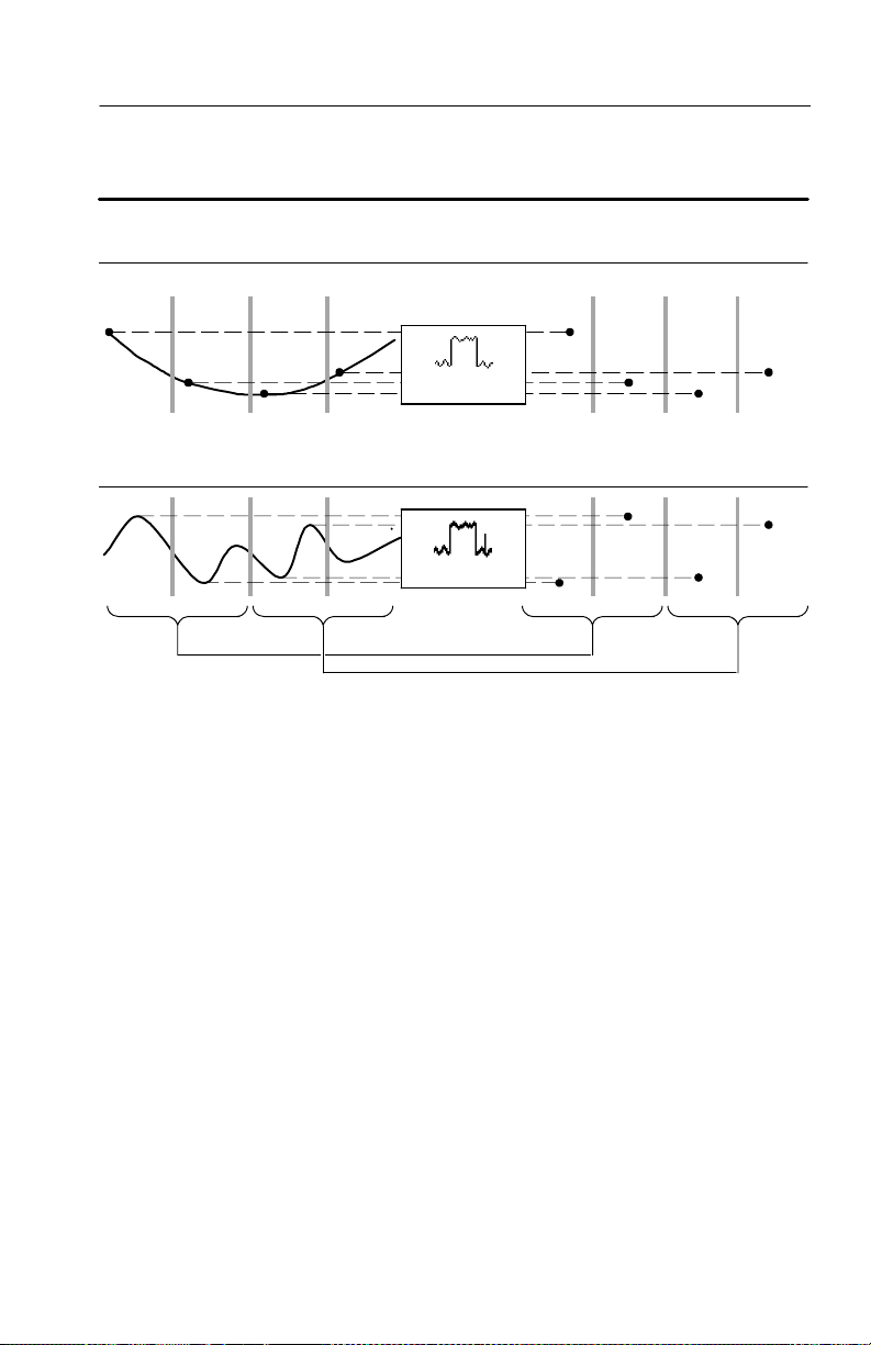
Acquisition Controls
Samples acquired in four
acquisition intervals
Interval 1 2 3 4 Interval 1 2 3 4
Sample mode acquires one sample in each interval.
Peak Detect mode uses the lowest and highest amplitudes from two consecutive intervals.
Acquisition
mode
Sample
Peak Detect
Displayed record points (at
maximum horizontal magnification)
Sample. Use Sample acquisition mode for the fastest acquisition at
any SEC/DIV setting. Sample mode is the default mode.
Peak Detect. Use Peak Detect acquisition mode to limit the possibility
of aliasing. Also, use Peak Detect for glitch detection. You can see
glitches as narrow as 1 ns.
Peak Detect is only functional for sample rates up to 125 MS/s. For
250 MS/s and faster sample rates, the oscilloscope reverts to Sample
acquisition mode, where the narrowest detectable pulse width is
1/(sample rate).
TDS3000B Series User Manual
3- 9
Page 94
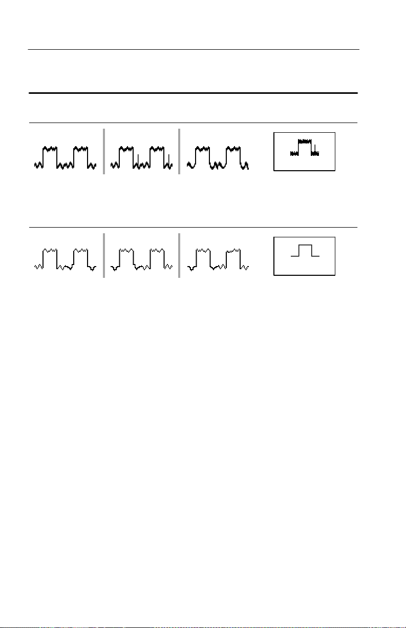
Acquisition Controls
Three acquisitions from one source Acquisition mode
Acquisition 1 2 3
Envelope
Envelope uses Peak Detect mode
for each individual acquisition.
Average uses Sample mode for
each individual acquisition.
Finds highest and
lowest record points over
many acquisitions
Average
Calculates average value
for each record point over
many acquisitions
Envelope. Use Envelope acquisition mode to capture the minimum
and maximum extremes of a signal over a specified number of
acquisitions (N). The enveloped waveform data acquisition clears
and then starts over after each N acquisitions. If you push the
SINGLE SEQ button, envelope acquisition stops after N acquisitions. Use the general purpose knob to set the num ber of acquisitions.
Average. Use Average acquisition mode to reduce random or
uncorrelated noise in the signal you want to display. The averaged
waveform is a running average over a specified number of
acquisitions (N). If you push the SINGLE SEQ button, average
acquisition stops after N acquisitions. Use the general purpose knob
to set the number of acquisitions.
3- 10
TDS3000B Series User Manual
Page 95
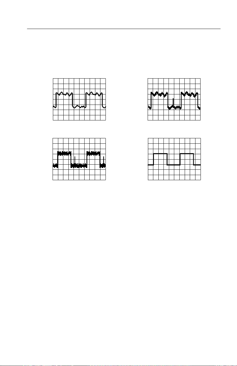
Acquisition Controls
If you probe a noisy square wave signal that contains intermittent,
narrow glitches, the waveform displayed will vary depending on the
acquisition mode you choose.
Sample Peak Detect
Envelope Average
TDS3000B Series User Manual
3- 11
Page 96

Acquisition Controls
Acquisition Resolution. You can choose either Normal or Fast Trigger
acquisition resolution. This setting determines the record length that
is acquired and affects the other factors shown in the ta ble below.
Factor Normal Fast trigger
Record length 10,000 points 500 points
Maximum acquisition rate:
300 MHz -- 600 MHz models
100 MHz -- 200 MHz models
Maximum horizontal zoom factor 200X 10X
Choose Normal or Fast Trigger acquisition resolution based on the
characteristi cs of the signal you want to acquire.
Signal characteristic Better choice
Large amount of horizontal detail Normal
700 waveforms/s
400 waveforms/s
3,600 waveforms/s
3,600 waveforms/s
3- 12
Shape is stable or changes relatively slowly Normal
Single shot Normal
High trigger repetition rate Fast Trigger
Shape changes rapidly Fast Trigger
Contains modulation Fast Trigger
TDS3000B Series User Manual
Page 97

Acquisition Controls
WaveAlertt Waveform Anomaly Detection. WaveAlert provides a way to
detect when a waveform deviates from a steady-state condition.
WaveAlert monitors the current waveform acquisition and compares
it to the previous DPO waveform acquisitions, using a sensitivity
value to adjust the comparision tolerance. If the current acquisition
exceeds the comparison tolerance, the oscilloscope considers the
current acquisition as an anomaly.
Anomaly
The oscilloscope can respond to an anomalous waveform by
stopping acquisitions, emitting a beep, saving the anomalous
waveform to a disk file, printing the screen image to a hard copy
device, or any combination of the above. You can also select to
highlight just the anomalous data in a waveform, or the entire
anomalous waveform.
TDS3000B Series User Manual
3- 13
Page 98

Acquisition Controls
To use WaveAlert, do the following steps:
1. Display the waveform or waveforms on t he scre en.
2. Push the Acquire MENU front-panel button.
3. Push the WaveAlert bottom menu button.
4. Push the Wfm Anomaly Detection side button to select On.
5. Push the Highlight Anomalies side button to select On.
6. Use the general purpose knob to set the comparison sensitivity
value. As signal noise and intensity levels affect the displayed
waveform, you will need to experiment with the sensitivity
setting to reduce the number of false anomalies due to signal
noise.
7. Use the WAVEFORM INTENSITY front-panel button to adjust
the persistance of the anomaly waveform.
8. Once you have set the sensitivity value to reduce or eliminate
false anomalies, push one or more side menu buttons to select the
actions to perform when the oscilloscope detects an anomaly.
3- 14
9. To restart WaveAlert while in Stop On Anomaly, push the
Acquire RUN/STOP front panel button.
TDS3000B Series User Manual
Page 99

Acquisition Controls
WaveAlert Key Points.
H You can use WaveAlert to monitor up to four waveforms or DPO
Math waveforms. However, adjacent waveforms can not touch or
overlap on the screen.
H To increase your chances of capturing an anomaly by acquiring
the maximum number of waveforms per second, set
ACQUIRE > Horizontal Resolution to Fast Trigger
(500 points).
H When WaveAlert is on, the front-panel WAVEFORM INTENSI-
TY knob controls the persistance of the anomalous waveform
instead of waveform intensity.
H To capture a very random event (minutes to hours), enable the
Wfms to Disk on Anomaly function to write anomalous
waveform data to a disk file in .isf format. The number of files
you can save depends on the waveform record length. You can
determine when the anomaly occured by checking the file create
date and time.
H You can use WaveAlert on DPO math waveforms.
H Changing the vertical or horizontal oscilloscope settings does not
affect the sensitivity setting. The sensitivity is calculated from
the new waveform data after changing the oscilloscope settings.
TDS3000B Series User Manual
3- 15
Page 100

Cursor
Cursor
Cursors are on-screen markers that you positon t o ta ke wave f orm
measurements. There are two cursor types: YT cursors and XY
cursors. The following section describes the YT cursors. Refer to
page 3--21 for informat ion on XY cursors.
YT Cursor Menu
The following YT cursor menu items are available while you are in
YT display mode (DISPLAY > XY Display > Off(YT)). Push the
CURSOR button to show the cursor menu.
CURSOR
Bottom Side Description
Function Off Turns cursors off.
HBars Use to make vertical measurements.
VBars Use to make both vertical and
horizontal measurements.
Bring Selected
Cursor to Center
Screen
BringBothCursors On Screen
Mode Independent Sets cursors to move independently.
Tracking Sets cursors to move together when
Moves the active cursor to center
screen.
Moves any off-screen cursor onto the
screen.
cursor 1 is selected.
3- 16
TDS3000B Series User Manual
 Loading...