

Page 1

Service Manual
TDS3000 Series
Digital Phosphor Oscilloscopes
071-0382-01
This document supports firmware version 2.00
and above.
Warning
The servicing instructions are for use by qualified
personnel only. To avoid personal injury, do not
perform any servicing unless you are qualified to
do so. Refer to all safety summaries prior to
performing service.
Page 2

Copyright © Tektronix, Inc. All rights reserved. T ektronix products are covered by U.S. and foreign patents, issued and pending. Information in this publication supercedes
that in all previously published material. Specifications and price change privileges reserved.
Printed in the U.S.A.
T ektronix, Inc., P.O. Box 1000, Wilsonville, OR 97070–1000
TEKTRONIX and TEK are registered trademarks of T ektronix, Inc.
Page 3

WARRANTY
T ektronix warrants that this product will be free from defects in materials and workmanship for a period of three (3) years
from the date of shipment. If any such product proves defective during this warranty period, T ektronix, at its option, either
will repair the defective product without charge for parts and labor, or will provide a replacement in exchange for the
defective product.
In order to obtain service under this warranty, Customer must notify Tektronix of the defect before the expiration of the
warranty period and make suitable arrangements for the performance of service. Customer shall be responsible for
packaging and shipping the defective product to the service center designated by T ektronix, with shipping charges prepaid.
T ektronix shall pay for the return of the product to Customer if the shipment is to a location within the country in which the
T ektronix service center is located. Customer shall be responsible for paying all shipping charges, duties, taxes, and any
other charges for products returned to any other locations.
This warranty shall not apply to any defect, failure or damage caused by improper use or improper or inadequate
maintenance and care. T ektronix shall not be obligated to furnish service under this warranty a) to repair damage resulting
from attempts by personnel other than T ektronix representatives to install, repair or service the product; b) to repair
damage resulting from improper use or connection to incompatible equipment; or c) to service a product that has been
modified or integrated with other products when the effect of such modification or integration increases the time or
difficulty of servicing the product.
THIS WARRANTY IS GIVEN BY TEKTRONIX WITH RESPECT TO THIS PRODUCT IN LIEU OF ANY
OTHER WARRANTIES, EXPRESSED OR IMPLIED. TEKTRONIX AND ITS VENDORS DISCLAIM ANY
IMPLIED WARRANTIES OF MERCHANTABILITY OR FITNESS FOR A PARTICULAR PURPOSE.
TEKTRONIX’ RESPONSIBILITY TO REPAIR OR REPLACE DEFECTIVE PRODUCTS IS THE SOLE AND
EXCLUSIVE REMEDY PROVIDED TO THE CUST OMER FOR BREACH OF THIS WARRANTY. TEKTRONIX
AND ITS VENDORS WILL NOT BE LIABLE FOR ANY INDIRECT , SPECIAL, INCIDENTAL, OR
CONSEQUENTIAL DAMAGES IRRESPECTIVE OF WHETHER TEKTRONIX OR THE VENDOR HAS
ADVANCE NOTICE OF THE POSSIBILITY OF SUCH DAMAGES.
Page 4

Page 5

Table of Contents
Specifications
Operating Information
Theory of Operation
General Safety Summary vii. . . . . . . . . . . . . . . . . . . . . . . . . . . . . . . . . . . .
Service Safety Summary xi. . . . . . . . . . . . . . . . . . . . . . . . . . . . . . . . . . . . .
Preface xiii. . . . . . . . . . . . . . . . . . . . . . . . . . . . . . . . . . . . . . . . . . . . . . . . . . .
Specifications 1–1. . . . . . . . . . . . . . . . . . . . . . . . . . . . . . . . . . . . . . . . . . . . . . . . . . . .
Transporting the Oscilloscope 2–2. . . . . . . . . . . . . . . . . . . . . . . . . . . . . . . . . . . . . . .
Connecting Power 2–3. . . . . . . . . . . . . . . . . . . . . . . . . . . . . . . . . . . . . . . . . . . . . . . .
Installing an Application Module 2–7. . . . . . . . . . . . . . . . . . . . . . . . . . . . . . . . . . . . .
Installing a Communication Module 2–9. . . . . . . . . . . . . . . . . . . . . . . . . . . . . . . . . .
Front-Panel Menus and Controls 2–10. . . . . . . . . . . . . . . . . . . . . . . . . . . . . . . . . . . . .
Front-Panel Connectors 2–18. . . . . . . . . . . . . . . . . . . . . . . . . . . . . . . . . . . . . . . . . . . .
Rear-Panel Connectors 2–19. . . . . . . . . . . . . . . . . . . . . . . . . . . . . . . . . . . . . . . . . . . . .
Probe Compensation 2–20. . . . . . . . . . . . . . . . . . . . . . . . . . . . . . . . . . . . . . . . . . . . . .
Self Calibration 2–21. . . . . . . . . . . . . . . . . . . . . . . . . . . . . . . . . . . . . . . . . . . . . . . . . .
Power Supply 3–1. . . . . . . . . . . . . . . . . . . . . . . . . . . . . . . . . . . . . . . . . . . . . . . . . . . .
Battery Board 3–2. . . . . . . . . . . . . . . . . . . . . . . . . . . . . . . . . . . . . . . . . . . . . . . . . . . .
Main Board 3–2. . . . . . . . . . . . . . . . . . . . . . . . . . . . . . . . . . . . . . . . . . . . . . . . . . . . . .
Display Module 3–3. . . . . . . . . . . . . . . . . . . . . . . . . . . . . . . . . . . . . . . . . . . . . . . . . .
Front-Panel Board 3–3. . . . . . . . . . . . . . . . . . . . . . . . . . . . . . . . . . . . . . . . . . . . . . . .
Disk Drive 3–3. . . . . . . . . . . . . . . . . . . . . . . . . . . . . . . . . . . . . . . . . . . . . . . . . . . . . .
Performance Verification
T est Record 4–2. . . . . . . . . . . . . . . . . . . . . . . . . . . . . . . . . . . . . . . . . . . . . . . . . . . . . .
Performance Verification Procedures 4–4. . . . . . . . . . . . . . . . . . . . . . . . . . . . . . . . . .
Adjustment Procedures
Required Equipment 5–1. . . . . . . . . . . . . . . . . . . . . . . . . . . . . . . . . . . . . . . . . . . . . . .
Overview of the Adjustment Process 5–2. . . . . . . . . . . . . . . . . . . . . . . . . . . . . . . . . .
Signal Connections 5–3. . . . . . . . . . . . . . . . . . . . . . . . . . . . . . . . . . . . . . . . . . . . . . . .
Factory Adjustment Procedure 5–6. . . . . . . . . . . . . . . . . . . . . . . . . . . . . . . . . . . . . . .
TDS3000 Series Service Manual
i
Page 6

Table of Contents
Maintenance
Options
Electrical Parts List
Diagrams
Preparation 6–1. . . . . . . . . . . . . . . . . . . . . . . . . . . . . . . . . . . . . . . . . . . . . . . . . . . . . .
Preventing ESD 6–1. . . . . . . . . . . . . . . . . . . . . . . . . . . . . . . . . . . . . . . . . . . . . . . . . .
Inspection and Cleaning 6–2. . . . . . . . . . . . . . . . . . . . . . . . . . . . . . . . . . . . . . . . . . . .
Removal and Installation Procedures 6–5. . . . . . . . . . . . . . . . . . . . . . . . . . . . . . . . . .
Troubleshooting 6–35. . . . . . . . . . . . . . . . . . . . . . . . . . . . . . . . . . . . . . . . . . . . . . . . . .
Troubleshooting Procedure 6–36. . . . . . . . . . . . . . . . . . . . . . . . . . . . . . . . . . . . . . . . .
Unpacking and Repacking Instructions 6–43. . . . . . . . . . . . . . . . . . . . . . . . . . . . . . . .
Options 7–1. . . . . . . . . . . . . . . . . . . . . . . . . . . . . . . . . . . . . . . . . . . . . . . . . . . . . . . . .
Electrical Parts List 8–1. . . . . . . . . . . . . . . . . . . . . . . . . . . . . . . . . . . . . . . . . . . . . . .
Diagrams 9–1. . . . . . . . . . . . . . . . . . . . . . . . . . . . . . . . . . . . . . . . . . . . . . . . . . . . . . .
Mechanical Parts List
Parts Ordering Information 10–1. . . . . . . . . . . . . . . . . . . . . . . . . . . . . . . . . . . . . . . . .
Using the Replaceable Parts List 10–2. . . . . . . . . . . . . . . . . . . . . . . . . . . . . . . . . . . . .
ii
TDS3000 Series Service Manual
Page 7

List of Figures
Table of Contents
Figure 3–1: TDS3000 series block diagram 3–1. . . . . . . . . . . . . . . . . . . . .
Figure 6–1: Pulling the hub pin 6–8. . . . . . . . . . . . . . . . . . . . . . . . . . . . . . .
Figure 6–2: Releasing the hub assembly 6–9. . . . . . . . . . . . . . . . . . . . . . . .
Figure 6–3: Reinstalling a hub cover 6–11. . . . . . . . . . . . . . . . . . . . . . . . . . .
Figure 6–4: Communication module guide 6–12. . . . . . . . . . . . . . . . . . . . . .
Figure 6–5: Flex cable to the disk drive 6–13. . . . . . . . . . . . . . . . . . . . . . . .
Figure 6–6: Removing the bezel from a new disk drive 6–14. . . . . . . . . . . .
Figure 6–7: Cables to the main board 6–15. . . . . . . . . . . . . . . . . . . . . . . . . .
Figure 6–8: Installing the fan, line filter, and line power cable 6–17. . . . . .
Figure 6–9: Installing the line filter and line power cable 6–18. . . . . . . . . .
Figure 6–10: Disk drive and display module cable connectors 6–20. . . . . .
Figure 6–11: Main Board 6–21. . . . . . . . . . . . . . . . . . . . . . . . . . . . . . . . . . . .
Figure 6–12: Front chassis 6–23. . . . . . . . . . . . . . . . . . . . . . . . . . . . . . . . . . .
Figure 6–13: Display module 6–24. . . . . . . . . . . . . . . . . . . . . . . . . . . . . . . . .
Figure 6–14: Front-panel cable routing 6–25. . . . . . . . . . . . . . . . . . . . . . . .
Figure 6–15: Disconnect back light cables 6–26. . . . . . . . . . . . . . . . . . . . . .
Figure 6–16: Remove inverter board 6–27. . . . . . . . . . . . . . . . . . . . . . . . . . .
Figure 6–17: Remove display from display chassis 6–28. . . . . . . . . . . . . . .
Figure 6–18: Remove back light tube 6–29. . . . . . . . . . . . . . . . . . . . . . . . . .
Figure 6–19: Installing display glass shield 6–30. . . . . . . . . . . . . . . . . . . . . .
Figure 6–20: Remove front-panel knobs 6–31. . . . . . . . . . . . . . . . . . . . . . . .
Figure 6–21: Remove front-panel board 6–32. . . . . . . . . . . . . . . . . . . . . . . .
Figure 6–22: Remove front-panel keypads 6–33. . . . . . . . . . . . . . . . . . . . . .
Figure 6–23: Checking front-panel lock nuts 6–34. . . . . . . . . . . . . . . . . . . .
Figure 6–24: Primary troubleshooting procedure 6–36. . . . . . . . . . . . . . . .
Figure 6–25: Power-on troubleshooting procedure 6–37. . . . . . . . . . . . . . .
Figure 6–26: AC power supply troubleshooting procedure 6–38. . . . . . . . .
Figure 6–27: Battery module troubleshooting procedure 6–39. . . . . . . . . .
Figure 6–28: Front panel/display backlight power troubleshooting 6–40.
Figure 6–29: Display/Main module supply voltage troubleshooting 6–41.
Figure 6–30: No display, power supply voltages OK 6–41. . . . . . . . . . . . . .
Figure 6–31: Module isolation troubleshooting procedure 6–42. . . . . . . . .
TDS3000 Series Service Manual
iii
Page 8

Table of Contents
Figure 10–1: Exploded view, front case half 10–4. . . . . . . . . . . . . . . . . . . . .
Figure 10–2: Exploded view, LCD display 10–6. . . . . . . . . . . . . . . . . . . . . .
Figure 10–3: Exploded view, main board and disk drive 10–8. . . . . . . . . .
Figure 10–4: Exploded view, circuit board assembly and fan 10–10. . . . . . .
Figure 10–5: Exploded view, rear case half 10–12. . . . . . . . . . . . . . . . . . . . . .
iv
TDS3000 Series Service Manual
Page 9

List of Tables
Table of Contents
Table 1–1: Specifications 1–1. . . . . . . . . . . . . . . . . . . . . . . . . . . . . . . . . . . .
Table 6–1: Internal inspection check list 6–3. . . . . . . . . . . . . . . . . . . . . . .
Table 6–2: Removal and installation procedures 6–6. . . . . . . . . . . . . . . . .
Table 7–1: TDS3000 Series options 7–1. . . . . . . . . . . . . . . . . . . . . . . . . . . .
TDS3000 Series Service Manual
v
Page 10

Table of Contents
vi
TDS3000 Series Service Manual
Page 11

General Safety Summary
Review the following safety precautions to avoid injury and prevent damage to
this product or any products connected to it. To avoid potential hazards, use this
product only as specified.
To Avoid Fire or Personal Injury
Use Proper Power Cord. Use only the power cord specified for this product and
certified for the country of use.
Connect and Disconnect Properly . Connect the probe output to the measurement
instrument before connecting the probe to the circuit under test. Disconnect the
probe input and the probe ground from the circuit under test before disconnecting
the probe from the measurement instrument.
Ground the Product. When operating from AC power, this product is grounded
through the grounding conductor of the power cord. To avoid electric shock, the
grounding conductor must be connected to earth ground. Before making
connections to the input or output terminals of the product, ensure that the
product is properly grounded.
When operating with battery power, this product must still be grounded. To
prevent electric shock, always connect a grounding wire between the ground
terminal on the rear panel and earth ground.
Observe All Terminal Ratings. To avoid fire or shock hazard, observe all ratings
and markings on the product. Consult the product manual for further ratings
information before making connections to the product.
Connect the ground lead of the probe to earth ground only.
Replace Batteries Properly. Replace batteries only with the proper type and rating
specified.
TDS3000 Series Service Manual
Recharge Batteries Properly. Recharge batteries for the recommended charge
cycle only.
Do Not Operate Without Covers. Do not operate this product with covers or panels
removed.
Use Proper Fuse. Use only the fuse type and rating specified for this product.
vii
Page 12
General Safety Summary
Avoid Exposed Circuitry. Do not touch exposed connections and components
when power is present.
Do Not Operate With Suspected Failures. If you suspect there is damage to this
product, have it inspected by qualified service personnel.
Do Not Operate in Wet/Damp Conditions.
Do Not Operate in an Explosive Atmosphere.
Keep Product Surfaces Clean and Dry .
Provide Proper Ventilation. Refer to the manual’s installation instructions for
details on installing the product so it has proper ventilation.
Symbols and Terms
T erms in this Manual. These terms may appear in this manual:
WARNING. Warning statements identify conditions or practices that could result
in injury or loss of life.
CAUTION. Caution statements identify conditions or practices that could result in
damage to this product or other property.
T erms on the Product. These terms may appear on the product:
DANGER indicates an injury hazard immediately accessible as you read the
marking.
WARNING indicates an injury hazard not immediately accessible as you read the
marking.
CAUTION indicates a hazard to property including the product.
Symbols on the Product. The following symbols may appear on the product:
viii
CAUTION
Refer to Manual
WARNING
High Voltage
Protective Ground
(Earth) Terminal
Battery
Information
TDS3000 Series Service Manual
Page 13

Preventing Electrostatic
Damage
General Safety Summary
CAUTION. Electrostatic discharge (ESD) can damage components in the
oscilloscope and its accessories. To prevent ESD, observe these precautions
when directed to do so.
Battery Recycling
Use a Ground Strap
. Wear a grounded antistatic wrist strap to discharge the static
voltage from your body while installing or removing sensitive components.
Use a Safe Work Area. Do not use any devices capable of generating or holding a
static charge in the work area where you install or remove sensitive components.
Avoid handling sensitive components in areas that have a floor or bench top
surface capable of generating a static charge.
Handle Components Carefully .
Do not slide sensitive components over any
surface. Do not touch exposed connector pins. Handle sensitive components as
little as possible.
Transport and Store Carefully.
Transport and store sensitive components in a
static-protected bag or container.
This product contains a Nickel Cadmium (NiCd) battery, which must be recycled
or disposed of properly. For the location of a local battery recycler in the U.S. or
Canada, please contact:
RBRC (800) BATTERY
Rechargeable Battery Recycling Corp. (800) 227-7379
P.O. Box 141870 www.rbrc.com
Gainesville, Florida 32614
TDS3000 Series Service Manual
ix
Page 14

General Safety Summary
x
TDS3000 Series Service Manual
Page 15

Service Safety Summary
Only qualified personnel should perform service procedures. Read this Service
Safety Summary and the General Safety Summary before performing any service
procedures.
Do Not Service Alone. Do not perform internal service or adjustments of this
product unless another person capable of rendering first aid and resuscitation is
present.
Disconnect Power. To avoid electric shock, switch off the instrument power, then
disconnect the power cord from the mains power.
Use Care When Servicing With Power On. Dangerous voltages or currents may
exist in this product. Disconnect power, remove battery (if applicable), and
disconnect test leads before removing protective panels, soldering, or replacing
components.
To avoid electric shock, do not touch exposed connections.
TDS3000 Series Service Manual
xi
Page 16

Service Safety Summary
xii
TDS3000 Series Service Manual
Page 17
Preface
Related Manuals
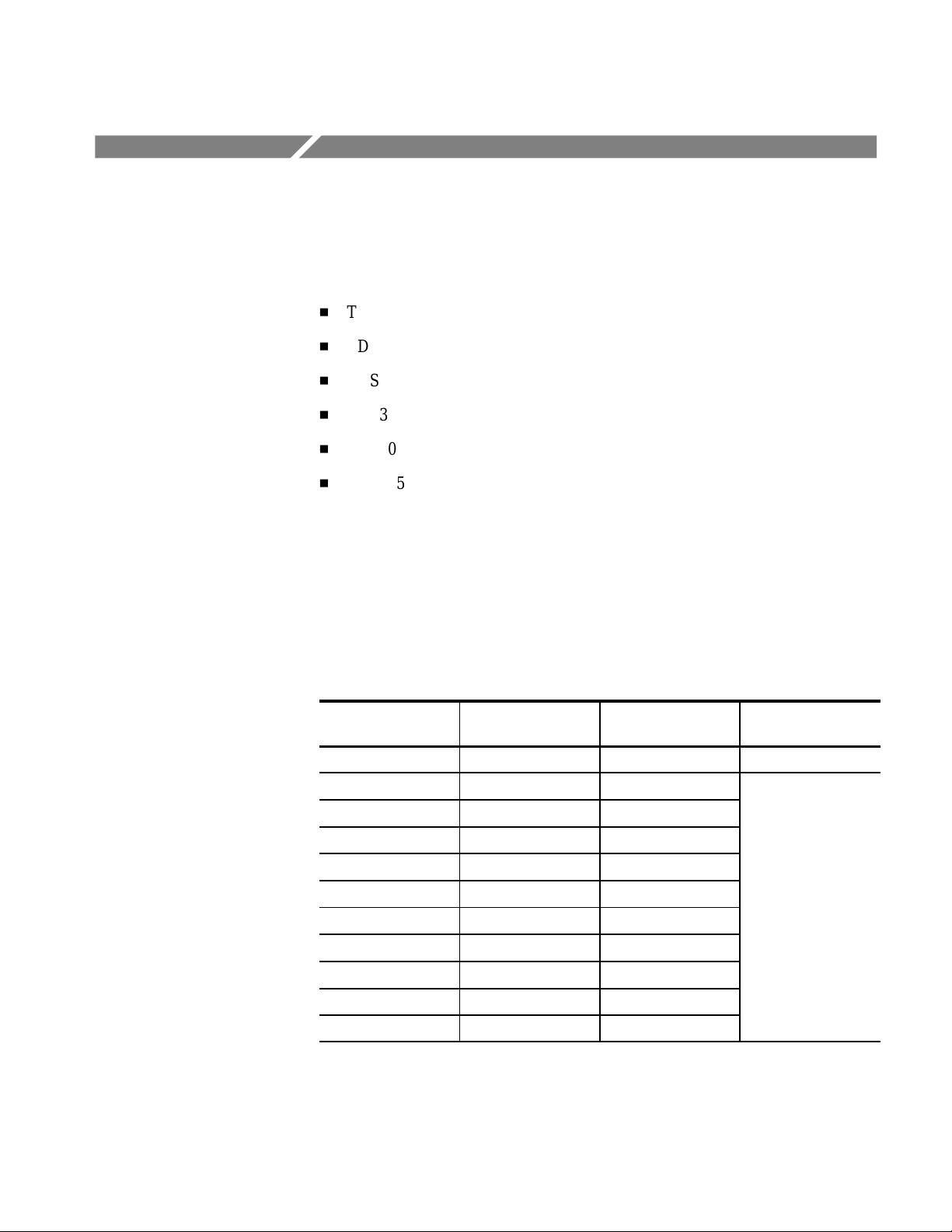
This is the Service Manual for the following TDS3000 Series Digital Phosphor
Oscilloscopes:
H
TDS3012
H
TDS3014
H
TDS3032
H
TDS3034
H
TDS3052
H
TDS3054
This manual provides information to troubleshoot and repair the instrument to
the module level.
Additional documentation for the instrument is contained in the related manuals
listed below.
Programmer
Language User manual Reference
English 071-0274-XX 071-0275-XX 071-0381-XX
French 071-0277-XX 071-0278-XX
German 071-0279-XX 071-0280-XX
Italian 071-0281-XX 071-0282-XX
Spanish 071-0283-XX 071-0284-XX
Portuguese 071-0285-XX 071-0286-XX
Korean 071-0287-XX 071-0288-XX
Simplified Chinese 071-0289-XX 071-0290-XX
Traditional Chinese 071-0291-XX 071-0292-XX
Japanese 071-0293-XX 071-0294-XX
Russian 071-0295-XX 071-0296-XX
manual
TDS3000 Series Service Manual
xiii
Page 18

Preface
Service Programs
Contacting Tektronix
Tektronix offers calibration service and a program to extend repair coverage
beyond the warranty period. These programs are cost-effective ways to maintain
genuine Tektronix service for your instrument. Ask your Tektronix distributor for
details.
Product
Support
Service
Support
For other
information
To write us Tektronix, Inc.
For application-oriented questions about a Tektronix measurement product, call toll free in North America:
1-800-TEK-WIDE (1-800-835-9433 ext. 2400)
6:00 a.m. – 5:00 p.m. Pacific time
Or contact us by e-mail:
tm_app_supp@tektronix.com
For product support outside of North America, contact your
local Tektronix distributor or sales office.
Contact your local Tektronix distributor or sales office. Or visit
our web site for a listing of worldwide service locations.
http://www.tektronix.com
In North America:
1-800-TEK-WIDE (1-800-835-9433)
An operator will direct your call.
P.O. Box 1000
Wilsonville, OR 97070-1000
xiv
TDS3000 Series Service Manual
Page 19

Specifications
S
Sequence
This appendix contains specifications for the TDS3000 series oscilloscopes. All
specifications are guaranteed unless noted as “typical.” Typical specifications are
provided for your convenience but are not guaranteed. Specifications that are
marked with the n symbol are checked in Performance Verification.
All specifications apply to all TDS3000 models unless noted otherwise. To meet
specifications, two conditions must first be met:
H
The oscilloscope must have been operating continuously for ten minutes
within the operating temperature range specified.
H
You must perform the Compensate Signal Path operation described on page
2–21. If the operating temperature changes by more than 10° C, you must
perform the Compensate Signal Path operation again.
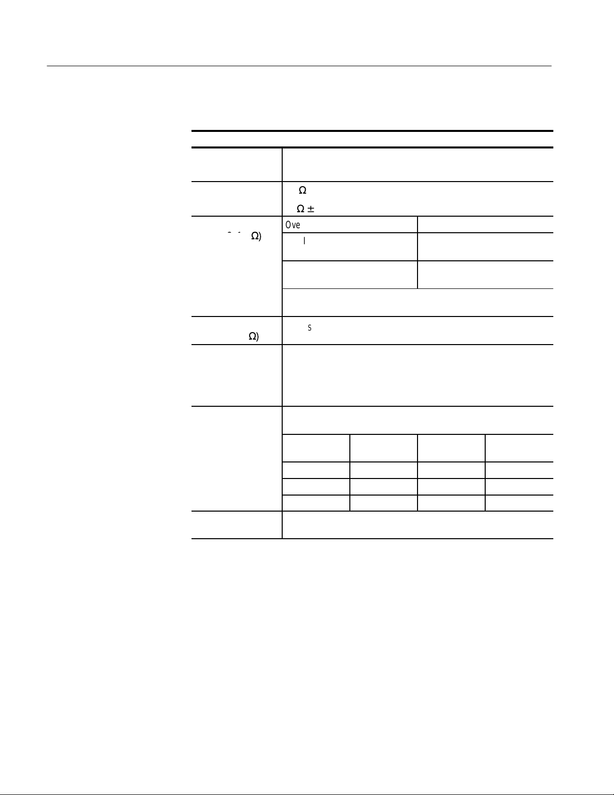
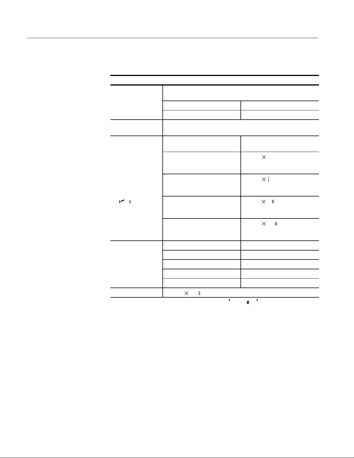
T able 1–1: Specifications
Acquisition
Acquisition modes Sample (Normal), Peak detect, Envelope, and Average
ingle
Acquisition mode Acquisition stops after
Sample, Peak Detect One acquisition, all channels
simultaneously
Average, Envelope N acquisitions, all channels
simultaneously, N is settable from
2 to 256 (or ∞ for Envelope)
TDS3000 Series Service Manual
1–1
Page 20
Specifications
C
T able 1–1: Specifications (cont.)
Inputs
Input coupling DC, AC, or GND
Channel input remains terminated when using GND coupling.
Input impedance,
DC coupled
Maximum voltage at
input BNC (1 M
W)
Maximum voltage at
input BNC (50
W)
Maximum floating
voltage
hannel-to-channel
crosstalk, typical
Differential delay ,
typical
1 MW ±1% in parallel with 13 pF ±2 pF, TekProbe compatible
50 W ±1%; VSWR ≤ 1.5:1 from DC to 500 MHz, typical
Overvoltage category Maximum voltage
CA T I Environment (refer to
page 1–11)
CA T II Environment (refer to
page 1–11)
For steady-state sinusoidal waveforms, derate at 20 dB/decade above
200 kHz to 13 Vpk at 3 MHz and above.
5 V
with peaks ≤ ±30 V
RMS
0 V from chassis (BNC) ground to earth ground, or
30 V
>30 V
(42 Vpk) only under these conditions: no signal voltages
RMS
(>42 Vpk), all common leads connected to the same voltage,
RMS
no grounded peripherals attached
Measured on one channel, with test signal applied to another channel,
and with the same scale and coupling settings on each channel
Frequency
range
≤ 100 MHz ≥ 100:1 ≥ 100:1 ≥ 100:1
≤ 300 MHz — ≥ 50:1 ≥ 50:1
≤ 500 MHz — — ≥ 30:1
100 ps between any two channels with the same scale and coupling
settings
TDS3012
TDS3014
150 V
RMS
100 V
RMS
TDS3032
TDS3034
(400 Vpk)
(400 Vpk)
TDS3052
TDS3054
1–2
TDS3000 Series Service Manual
Page 21
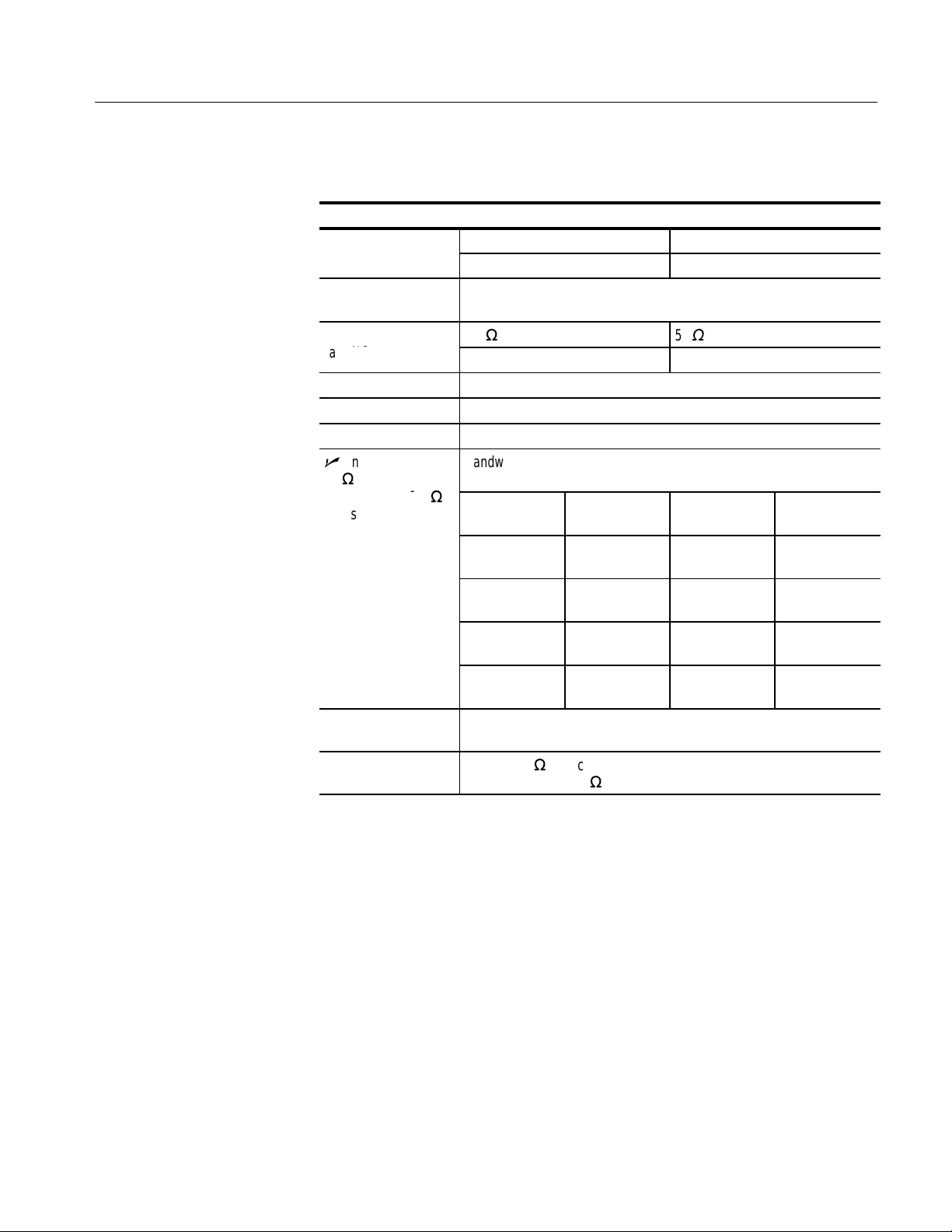
T able 1–1: Specifications (cont.)
Number of
s
SCA
Vertical
channel
Digitizers 9-bit resolution, separate digitizers for each channel sample
LE Range
(at BNC)
Fine SCALE Adjustable with ≥ 1% resolution
Polarity Normal and Invert
Position range ±5 divisions
n
Analog bandwidth,
50 W
(also typical at 1 M
with standard probe)
Calculated rise
time, typical
Analog bandwidth
limit, typical
Lower frequency limit,
AC coupled, typical
TDS3012, TDS3032, TDS3052 TDS3014, TDS3034, TDS3054
2 plus external trigger input 4
simultaneously
1 M
W
1 mV/div to 10 V/div
Bandwidth limit set to Full, operating ambient ≤30 °C, derate 1%/°C
above 30 °C
W
Scale range TDS3012
TDS3014
5 mV/div to
1 V/div
2 mV/div to
4.98 mV/div
1 mV/divto
1.99 mV/div
— 3.5 ns 1.2 ns 0.7 ns
Selectable between 20 MHz, 150 MHz (not available on TDS3012 or
TDS3014), or Full
7 Hz for 1 MW, reduced by a factor of ten when using a 10X passive
probe; 140 kHz for 50
100 MHz 300 MHz 500 MHz
100 MHz 250 MHz 300 MHz
90 MHz 150 MHz 175 MHz
W
50
W
1mV/div to 1 V/div
TDS3032
TDS3034
Specifications
TDS3052
TDS3054
TDS3000 Series Service Manual
1–3
Page 22
Specifications
response
Offset r
e
T able 1–1: Specifications (cont.)
Vertical
Peak detect or
Envelope pulse
, typical
DC gain accuracy ± 2%, derated at 0.07%/°C for temperatures below +18° C and above
DC measurement
accuracy
Sample acquisition
mode, typical
n
Average
acquisition mode
(≥16 averages)
ang
Offset accuracy ± (0.005 | offset – position| + 0.1 div)
1 0.02 term (gain component) derated at 0.00025/°C above 30° C
Minimum width of pulse with amplitude of ≥2 div to capture 50% or
greater amplitude
Sample rates ≤125 MS/s Sample rates ≥250 MS/s
1 ns 1/sample rate
+28° C, in Sample or Average acquisition mode
Measurement type DC Accuracy (in volts)
Absolute measurement of any
waveform point, and High, Low,
Max, and Min measurements.
Delta voltage between any two
points on a waveform, and all
other automatic measurements.
Absolute measurement of any
waveform point, and High, Low,
Max, and Min measurements.
Delta voltage between two points
on a waveform, and all other
automatic measurements.
Scale range Offset range
1 mV/div to 9.95 mV/div ±100 mV
10 mV/div to 99.5 mV/div ±1 V
100 mV/div to 995 mV/div ±10 V
1V/div to 10 V/div ±100 V
± [0.021 | reading – (offset –
position)| + offset accuracy +
0.15 div + 0.6 mV]
± [0.021 | reading| + 0.15 div
+ 1.2 mV]
1
± [0.02
| reading – (offset –
position)| + offset accuracy
+ 0.1 div]
± [0.021 | reading| + 0.05 div]
1–4
TDS3000 Series Service Manual
Page 23
T able 1–1: Specifications (cont.)
Sample rate r
e
m
e
sens
sens
Horizontal
Acquisition (horizontal) resolution
Record length 10,000 points 500 points
Acquisition rate,
maximum
ang
Seconds/division
range
n
Sample rate and
delay time accuracy
Trigger
External trigger input,
typical
External trigger
aximum voltag
External trigger maximum floating voltage
n
Edge trigger
itivity
Edge trigger
itivity , typical
Normal Fast trigger
Up to 450 waveforms/s Up to 3,000 waveforms/s
Acquisition resolution
Normal 100 S/s to
Fast trigger 5 S/s to
— 4 ns/div to
TDS3012
TDS3014
1 GS/s
1.25 GS/s
10 s/div
TDS3032
TDS3034
100 S/s to
2.5 GS/s
5 S/s to
2.5 GS/s
2 ns/div to
10 s/div
±200 ppm over any ≥1 ms time interval
1 MW in parallel with 17 pF, TekProbe compatible
(TDS3012, TDS3032, TDS3052 only)
Overvoltage category Maximum voltage
CA T I Environment (refer to
150 V
page 1–11)
CA T II Environment (refer to
100 V
page 1–11)
For steady-state sinusoidal waveforms, derate at 20 dB/decade above
200 kHz to 13 Vpk at 3 MHz and above.
0 V from chassis (BNC) ground to earth ground
30 V
>30 V
(42 Vpk) only under these conditions: no signal voltages
RMS
(>42 Vpk), all common leads connected to the same voltage,
RMS
no grounded peripherals attached
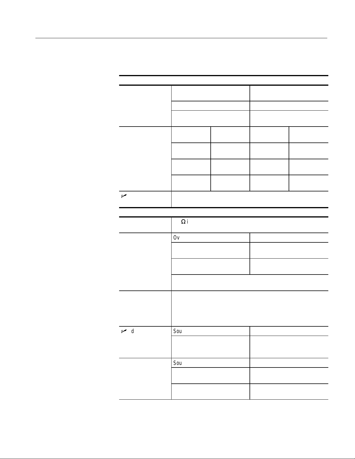
Source Sensitivity
Any channel, DC coupled 0.35 div from DC to 50 MHz,
increasing to 1 div at oscilloscope
bandwidth
Source Sensitivity
External trigger
100 mV from DC to 50 MHz,
increasing to 500 mV at 300 MHz
External/10 trigger 500 mV from DC to 50 MHz,
increasing to 3 V at 300 MHz
RMS
RMS
(400 Vpk)
(400 Vpk)
Specifications
TDS3052
TDS3054
100 S/s to
5 GS/s
5 S/s to
5 GS/s
1 ns/div to
10 s/div
TDS3000 Series Service Manual
1–5
Page 24

Specifications
sens
Tr
e
Tr
-
r
T able 1–1: Specifications (cont.)
Trigger
Edge trigger
itivity , typical
igger level rang
SET LEVEL TO 50%,
typical
igger level accu
acy , typical
Trigger holdoff range 250.8 ns to 10 s
Video trigger sensitiv-Triggers on negative sync of NTSC, PAL, or SECAM signal
ity, typical
B Trigger Trigger After Time Trigger After B Events
Range 13.2 ns to 50 s 1 event to 9,999,999 events
Minimum time
between arm and
trigger, typical
Minimum Pulse
Width, typical
Maximum Frequency , typical
Any channel, NOISE REJ coupled 3.5 times the DC-coupled limits
Any channel, HF REJ coupled 1.5 times the DC-coupled limit
from DC to 30 kHz, attenuates
signals above 30 kHz
Any channel, LF REJ coupled 1.5 times the DC-coupled limits
for frequencies above 80 kHz,
attenuates signals below 80 kHz
Source Sensitivity
Any channel ±8 divisions from center of
screen, ±8 divisions from 0 V if LF
REJ trigger coupled
External external ±800 mV
External/10 trigger ±8 V
Line Fixed at the midlevel of the AC
line
Operates with input signals ≥45 Hz
Source Sensitivity
Any channel ±0.2 divisions
External trigger ±20 mV
External/10 trigger ±200 mV
Line N/A
Source
Any channel 0.6 to 2.5 divisions of video sync
External trigger 150 mV to 625 mV of video sync
External/10 trigger 1.5 V to 6.25 V of video sync tip
5ns from the end of the time
period and the B trigger event
— B event width, 2 ns
— B event frequency, 250 MHz
Sensitivity
tip
tip
5 ns between the A trigger event
and the first B trigger event
1–6
TDS3000 Series Service Manual
Page 25

Specifications
T able 1–1: Specifications (cont.)
Display
Display screen 6.5 in (165 mm) diagonal color liquid crystal
Display resolution 640 horizontal by 480 vertical pixels
Backlight intensity,
typical
Display color Up to 16 colors, fixed palette
External display filter Scratch-resistant tempered glass
I/O ports
Parallel printer port Centronics compatible, DB-25 female connector
GPIB interface Available as optional accessory TDS3GM
RS-232 interface Available as optional accessory TDS3GM or TDS3VM,
VGA signal output Available as optional accessory TDS3VM, DB-15 female connector,
Probe compensator
output, typical
Miscellaneous
Nonvolatile memory Typical retention time ≥ 5 years for front-panel settings, unlimited for
Floppy disk 3.5 in, DOS format, 720 KB or 1.44 MB compatible
Internal clock Provides date/time stamp for stored data and the current time and date
Radiated immunity Per methods of EN50082-1 and EN61000-4-3, the increase in trace
200 cd/m
DB-9 male connector
31.6 kHz sync rate, EIA RS-343A compliant
5.0 V into ≥1 MW load,
frequency = 1 kHz
saved waveforms and setups
to the front panel, if enabled. Y ear-2000 compliant.
noise is not to exceed four major divisions peak-to-peak. Ambient RF
fields may induce triggering when trigger threshold is offset less than
two major divisions from ground reference.
2
TDS3000 Series Service Manual
1–7
Page 26

Specifications
T able 1–1: Specifications (cont.)
Power sources
AC line power Operates the oscilloscope and charges the optional internal battery
Source voltage 90 V
Source frequency 47 Hz to 440 Hz
Power consump-
tion
Battery power Optional accessory TDS3BAT, rechargeable NiCad battery pack
Operating time,
typical
Battery charge
time, typical
Line fuse Internal, not user replaceable
Environmental
Temperature Operating range (no disk installed): +5 °C to +50 °C
75 W maximum
2 hours, depending on operating conditions
18 hours in the oscilloscope, 3 hours in the optional external charger
TDS3CHG
RMS
to 250 V
, continuous range (CAT II)
RMS
Nonoperating range (no disk installed): –20 °C to +60 °C
Typical operating range for floppy disks: +10 °C to +50 °C
Humidity Operating range (no disk installed): 20% to 80% RH below 32 °C,
derate upper limit to 21% RH at 50 °C
Nonoperating range (no disk installed): 5% to 90% RH below 41 °C,
derate upper limit to 30% RH at 60 °C
Typical operating range for floppy disks: 20% to 80% RH below 32 °C,
derate upper limit to 21% RH at 50 °C
Pollution Degree Pollution Degree 2: Typical home or office environment.
1–8
TDS3000 Series Service Manual
Page 27

T able 1–1: Specifications (cont.)
Environmental
Altitude Operating limit: 3000 m
Nonoperating limit: 15,000 m
Random vibration Operating: 0.31 g
Nonoperating: 2.46 g
axis
Drop resistance, typical
Mechanical
Size Height: 176 mm (6.9 in), 229 mm (9.0 in) including handle
Weight Oscilloscope only: 3.2 kg (7.0 lbs)
Survives a 152 mm (6 in) drop onto concrete with only cosmetic
damage
Width: 375 mm (14.75 in)
Depth: 149 mm (5.9 in)
from 5 Hz to 500 Hz, 10 minutes on each axis
RMS
from 5 Hz to 500 Hz, 10 minutes on each
RMS
Specifications
With accessories and carry case: 4.1 kg (9.0 lbs)
When packaged for domestic shipment: 5.5 kg (12.0 lbs)
Optional battery pack: 2 kg (4.5 lbs)
TDS3000 Series Service Manual
1–9
Page 28

Specifications
T able 1–1: Specifications (cont.)
EMC certifications and compliances
EMC Compliance:
European Union
EMC Compliance:
Australia/New Zealand
EMC Compliance:
Russia
FCC Compliance:
U.S.A.
Meets intent of Directive 89/336/EEC for Electromagnetic Compatibility.
Compliance was demonstrated to the following specifications as listed
in the Official Journal of the European Communities:
EN 55011 Class A Radiated and Conducted Emissions
EN 50082-1 Immunity
Meets the intent of Australian EMC Framework as demonstrated to the
following specification:
AS/NZS 2064.1/2
This product was certified by the GOST ministry of Russia to be in
compliance with all applicable EMC regulations.
Emissions comply with FCC Code of Federal Regulations 47, Part 15,
Subpart B, Class A Limits
1–10
TDS3000 Series Service Manual
Page 29

Specifications
T able 1–1: Specifications (cont.)
Safety certifications and compliances
EC Declaration of
Conformity – Low
Voltage
(TDS3000 Series
and P3010)
(P3010) EN 61010-2-031:1995
(P6139A) HD401 S1
Approvals
(TDS3000 Series
and P3010)
(P3010) EN 61010-2-031:1995 – Particular requirements for hand-held probe
(P6139A) UL1244, Third Edition– Electronic measuring and test equipment
Installation Category
Descriptions
Compliance was demonstrated to the following specification as listed in
the Official Journal of the European Communities:
Low Voltage Directive 73/23/EEC as ammended by 93/68/EEC
EN 61010-1/A2:1995
Safety requirements for electrical equipment for
measurement, control, and laboratory use
Particular requirements for hand-held probe assemblies
for electrical measurement and test equipment
Safety requirements for electronic apparatus
UL31 11-1 –Standard for electrical measuring and test equipment
CAN/CSA C22.2 No. 1010.1 – Safety requirements for electrical
equipment for measurement, control and laboratory use
assemblies for electrical measurement and test equipment
CAN/CSA C22.2 No. 231.1-M89 – Test probes
Terminals on this product may have different installation category
designations. The installation categories are:
CA T III Distribution-level mains (usually permanently
connected). Equipment at this level is typically in a
fixed industrial location
CA T II Local-level mains (wall sockets). Equipment at this
level includes appliances, portable tools, and similar
products. Equipment is usually cord-connected
CA T I Secondary (signal level) or battery operated circuits of
electronic equipment
TDS3000 Series Service Manual
1–11
Page 30

Specifications
1–12
TDS3000 Series Service Manual
Page 31

Operating Information
This chapter provides an overview of the following topics:
H
Transporting the oscilloscope
H
Connecting power and using the battery pack
H
Installing an application module
H
Installing a communication module
H
Front-panel menus and controls
H
Front- and rear-panel connectors
H
Probe compensation
H
Self calibration
For more detailed information about operating information, see the TDS3000
Series User Manual.
For information about unpacking and inspecting the instrument, see Unpacking
and Repacking Instructions on page 6–43 of this manual.
TDS3000 Series Service Manual
2–1
Page 32

Operating Information
Transporting the Oscilloscope
When transporting the oscilloscope, wrap the cord around the handle as shown
below. Use the supplied cord retainer if the power plug does not have a
molded-in retainer. The oscilloscope front cover has a convenient place to store
the Reference Manual.
2–2
If you are not using a battery, use the accessory tray in the battery compartment
to store probes and other accessories.
CAUTION. To avoid damage to the disk drive, do not transport the oscilloscope
with a floppy disk in the disk drive.
TDS3000 Series Service Manual
Page 33

Connecting Power
Operating Information
To connect a power cord, do these steps:
1. Open the strain relief and slip it over the power cord.
2. Snap the strain relief into its hole in the rear panel of the oscilloscope.
3. Connect the power cord to the power input connector.
You can operate the oscilloscope from a grounded mains supply with line voltage
between 90 V
oscilloscope is grounded through the power cord. The line fuse is internal and is
not user replaceable.
and 250 VAC and frequency between 47 Hz and 440 Hz. The
AC
Using Battery Power
TDS3000 Series Service Manual
You can operate the oscilloscope continuously for approximately two hours from
the rechargeable battery pack. A triangle icon in the display (
battery is in use, a power-plug icon (
and a gauge icon (
turns off automatically when the battery runs low; a low-battery message appears
in the display about ten minutes before the automatic shutdown.
NiCad batteries appear to lose capacity if not allowed to occasionally discharge
completely. Every few months, run your oscilloscope until it shuts down and
then recharge the battery completely to keep your battery pack at peak performance.
Refer to the General Safety Summary for information about proper nickel-cadmium battery disposal.
) shows the charge level in the battery. The oscilloscope
) shows when line power is connected,
) shows when the
2–3
Page 34

Operating Information
Operating Safely with
Battery Power
WARNING. To avoid electric shock, always connect the rear-panel ground
terminal to earth ground when operating the instrument from battery power.
For safe operation, the oscilloscope chassis must remain at earth ground potential
even when operating from battery power. Without a connection between the
chassis and earth ground, you can receive a shock from exposed metal on the
chassis if you connect an input to a hazardous voltage (>30 V
, >42 Vpk).
RMS
Protection against this condition is provided when you attach the Tektronix-supplied grounding wire from the terminal on the rear panel to earth ground. If you
use a different grounding wire, it must be at least 18 gauge.
When you start to use the battery pack, an on-screen message reminds you to
connect the grounding wire between the ground terminal on the rear panel and
earth ground.
2–4
TDS3000 Series Service Manual
Page 35

Operating Information
Installing and Removing
the Battery
To install the optional battery pack, do these steps:
1. Open the battery compartment door on the rear panel and remove the
accessory tray.
Battery door
(Opened)
2. Slide the battery into the compartment and press it in from both sides until
you hear the latches click.
3. Press on both sides of the battery compartment door to snap it closed.
To remove the battery, do these steps:
1. Open the battery compartment door.
2. Lift the battery handles and pull the battery out of the oscilloscope.
TDS3000 Series Service Manual
2–5
Page 36

Operating Information
Charging the Battery
The battery charges automatically when the oscilloscope is connected to line
power. You can also charge the battery with the optional external charger
(TDS3CHG).
Configuration Typical charging time
Battery charging in oscilloscope with oscilloscope turned on or off
Battery charging with TDS3CHG external
charger
18 hours
3 hours
NOTE. Charge the battery before using it for the first time or after prolonged
storage.
2–6
TDS3000 Series Service Manual
Page 37

Installing an Application Module
CAUTION. To avoid damage to the oscilloscope or application module, observe
the ESD precautions described on page ix.
Optional application modules are available to extend the capability of your
oscilloscope. You can install up to four application modules at one time.
Application modules can go into the two slots with windows in the upper right
corner of the front panel. Two additional slots are located behind the two you can
see. To install an application module, do these steps:
1. Save any oscilloscope settings and/or reference waveforms you want to keep
to floppy disk before doing these steps.
2. Turn the oscilloscope power off.
3. Open the small door in the upper right corner of the front panel.
4. Slide the application module into any available slot with the module contacts
facing the circuit board. If it is necessary to make space for a new application
module, use a small flat-bladed screwdriver in the molded depression on the
end of a module to slide an installed module out of a slot.
Operating Information
NOTE. If you remove an application module, the features provided by the
application module become unavailable. You can reinstall the module to restore
the features.
5. Close the module door.
Application modules
Contacts
TDS3000 Series Service Manual
2–7
Page 38

Operating Information
6. If the application module came with one or more floppy disks, insert the
firmware upgrade floppy disk into the disk drive. If there is more than one
floppy disk, insert firmware upgrade floppy disk number one into the disk
drive.
7. Power on the oscilloscope. The oscilloscope determines whether the
firmware update is necessary. If no firmware update is necessary, the
oscilloscope powers on with no messages. Go to step 9.
8. Push OK Load New Firmware to begin loading the firmware. During the
process, the oscilloscope may instruct you to insert a second floppy disk;
insert the second firmware disk at that time. When the firmware upgrade is
complete, the oscilloscope will restart automatically with the new firmware.
NOTE. If you power off the oscilloscope, eject a floppy disk, or there is a power
outage during the upgrade process, you must power off the oscilloscope and do
the firmware upgrade procedure, starting at step 6, before you can use the
oscilloscope.
9. Remove the floppy disk.
2–8
TDS3000 Series Service Manual
Page 39
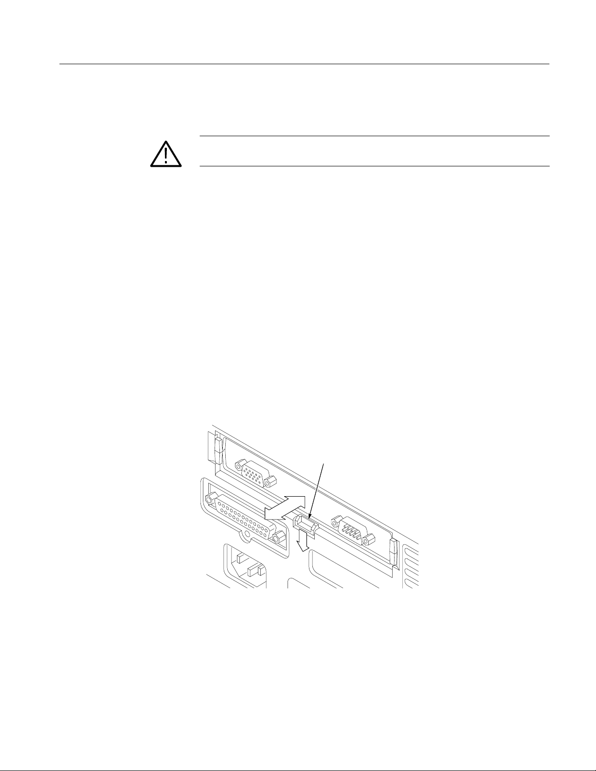
Installing a Communication Module
CAUTION. To avoid damage to the oscilloscope or communication module,
observe the ESD precautions described on page ix.
To install one of the optional communications modules, do these steps:
1. Turn the oscilloscope power off.
2. Press down on the latching tab to remove the blank cover.
3. Slide the communication module into the compartment until the internal
connectors are seated and the latching tab locks.
4. Turn power on. The communication module is now ready for your use.
To remove a communication module, do these steps:
1. Turn the oscilloscope power off.
Operating Information
2. Press down on the latching tab and then use a small screwdriver to alternate-
ly pry out the sides of the communication module.
3. Slide out the communication module and store it in an ESD-shielded bag.
Install the blank cover if no other communication module is to be installed.
Latching tab
TDS3000 Series Service Manual
2–9
Page 40

Operating Information
Front-Panel Menus and Controls
The front panel has buttons and controls for the functions you use most often.
The front panel has menus to access more specialized functions.
Using the Menu System
To use the menu system, follow the steps shown on the next two pages.
1. Push a dark-colored front-panel menu button to display the menu you want
to use.
MEASURE SAVE/RECALL QUICKMENU
UTILITYDISPLAYCURSOR
VERTICAL HORIZONTAL TRIGGER ACQUIRE
2. Push a bottom screen button to select a menu item. If a pop-up menu
appears, continue to push the screen button to select an item from the pop-up
menu.
2–10
TDS3000 Series Service Manual
Page 41

Operating Information
3. Push a side screen button to choose a menu item. If the menu item contains
more than one choice, push the side screen button again to make the choice.
4. Certain menu choices require you to set a numerical value to complete the
setup. Use the general purpose knob to adjust the parameter value. Push the
COARSE button to make larger adjustments.
SELECT
COARSE
VERTICAL
POSITION
TDS3000 Series Service Manual
2–11
Page 42

Operating Information
Using the Menu Buttons
You can use the menu buttons to perform many functions in the oscilloscope.
MEASURE SAVE/RECALL QUICKMENUSELECT
COARSE
21 4365
1. MEASURE. Performs automated measurements of waveforms.
2. CURSOR. Activates the cursors.
3. SAVE/RECALL. Saves and recalls setups and waveforms to memory or a floppy disk.
4. DISPLAY. Changes the appearance of waveforms and the display screen.
5. QUICKMENU. Activates QuickMenus such as the built-in Quick Scope feature.
6. UTILITY. Activates the system utility functions, such as selecting a language.
VERTICAL HORIZONTAL TRIGGER ACQUIRE
POSITION POSITION LEVEL
UTILITYDISPLAYCURSOR
2–12
SCALE SCALE
WAVEFORM
INTENSITY
987
7. Vertical MENU. Adjusts the scale, position, and offset of waveforms. Sets the input
parameters.
8. Trigger MENU. Adjusts the trigger functions.
9. Acquire MENU. Sets the acquisition modes and horizontal resolution, and resets the
delay time.
TDS3000 Series Service Manual
Page 43
Operating Information
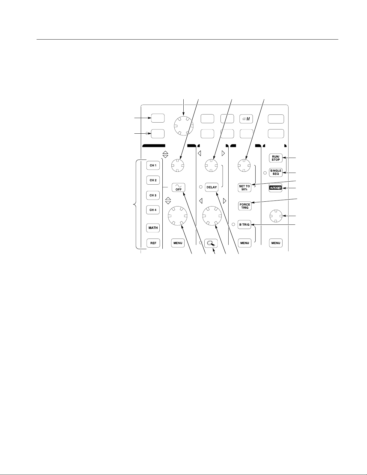
Using the Dedicated
Controls
These dedicated buttons and controls generally control waveforms and cursors
without the use of menus.
34 5 6
SELECT MEASURE SAVE/RECALL QUICKMENU
2
COARSE UTILITYDISPLAYCURSOR
1
VERTICAL HORIZONTAL TRIGGER ACQUIRE
19
POSITION POSITION LEVEL
SCALE SCALE
WAVEFORM
INTENSITY
7
8
9
10
11
12
13
14151618 17
1. COARSE. Causes the general purpose knob and position knobs to make adjustments
more quickly.
2. SELECT . Toggles between the two cursors to select the active cursor .
3. General purpose knob. Moves the cursors. Sets numerical parameter values for some
menu items. Push COARSE to make adjustments quickly.
4. Vertical POSITION. Adjusts the vertical position of the selected waveform. Push
COARSE to make adjustments more quickly.
5. Horizontal POSITION. Adjusts the trigger point location relative to the acquired
waveforms. Push COARSE to make adjustments quickly.
6. Trigger LEVEL. Adjusts the trigger level.
7. RUN/STOP. Stops and restarts acquisition.
8. SINGLE SEQ. Sets acquisition, display, and trigger parameters for a single-shot
(single-sequence) acquisition.
9. SET TO 50%. Sets the trigger level to the midpoint of the waveform.
10. AUTOSET. Automatically sets the vertical, horizontal, and trigger controls for a usable
display .
11. FORCE TRIG. Forces an immediate trigger event.
TDS3000 Series Service Manual
2–13
Page 44
Operating Information
12. WAVEFORM INTENSITY. Controls waveform intensity.
13. B TRIG. Activates the B trigger. Changes the trigger menu to set the B-trigger
parameters.
14. DELAY. Enables delayed acquisition relative to the trigger event. Use horizontal
POSITION to set the amount of delay.
15. Horizontal SCALE. Adjusts the horizontal scale factor.
16. Horizontal zoom. Splits the screen and magnifies the current acquisition horizontally.
17. Waveform OFF. Removes the selected waveform from the display.
18. Vertical SCALE. Adjusts the vertical scale factor of the selected waveform.
19. CH1, CH2, (CH3, CH4,) MATH. Displays a waveform and chooses the selected
waveform. REF shows the reference waveform menu.
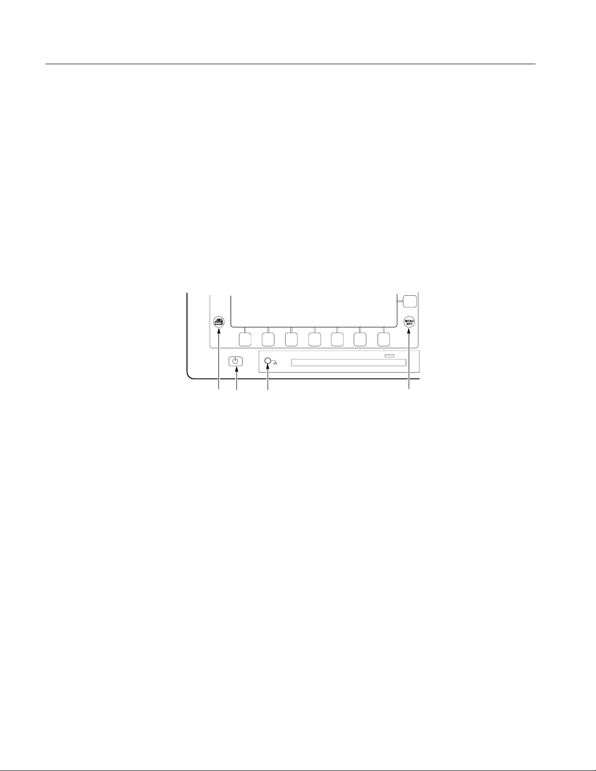
20 2321 22
20. Hard copy. Initiates a hard copy using the port selected in the Utility menu.
21. Power switch. Turns power to on or standby.
22. Wrist-strap ground. Use to connect a wrist strap when working with ESD-sensitive
circuits. This connector is not a safety ground.
23. MENU OFF. Clears menu from the display.
2–14
TDS3000 Series Service Manual
Page 45
Operating Information
Identifying Items in the
Display
The following items may appear in the display; not all items are visible at any
given time. Some readouts move outside the graticule area when menus are
turned off.
7
6
8
9
10
13
2 3 4 5
1
12
11
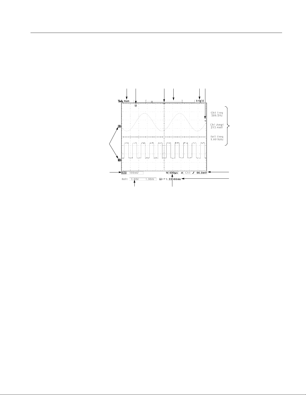
1. Waveform baseline icons show the zero-volt level of the waveforms (ignoring the effect
of offset). The icon colors correspond to the waveform colors.
2. Acquisition readout shows when acquisition is running, stopped, or when acquisition
preview is in effect.
3. Trigger position icon shows the trigger location in the waveforms.
4. Expansion point icon shows the point that the horizontal scale expands and compresses
around.
5. Waveform record icon shows the trigger location relative to the waveform record. The
line color corresponds to the selected waveform color.
6. Trigger status readout show trigger status.
7. Trigger level icon shows the trigger level on the waveform. The icon color corresponds
to the trigger source channel color.
8. Cursor and measurement readouts show results and messages.
9. Trigger readouts show the trigger sources, slopes, and levels, and position.
10. Readout shows the delay setting or the trigger location within the record.
11. Horizontal readout shows the main or zoom time/division.
12. Auxiliary waveform readouts show the vertical and horizontal scale factors of the math
or reference waveforms.
13. Channel readouts show the channel scale factor, coupling, input resistance, bandwidth
limit, and invert status.
TDS3000 Series Service Manual
2–15
Page 46

Operating Information
14 15
14. A triangle icon with the battery icon indicates that a battery is installed and battery
power is in use. The battery icon shows the approximate charge level of the battery. See
page 2–4 for important safety information.
15. A power-plug icon with the battery icon indicates that a battery is installed but line
power is in use. The battery may be charging. The battery icon shows the approximate
charge level.
Using Quick Menus
The QuickMenu feature simplifies the use of the oscilloscope. When you push
the QUICKMENU button, a set of frequently used menu functions show on the
display. Then, push the screen buttons around the display to operate the
QuickMenu.
Using Quick Scope. Quick Scope is one type of QuickMenu that you can use to
control the basic oscilloscope functions. You can perform many tasks without
using the regular menu system. If you need to use a function that is not contained
in the Quick Scope menu, push the button you would normally push to access
that function. For example, if you want to add an automatic measurement, push
the MEASURE button to set up the measurement. Then, push the QUICKMENU
button to return to the Quick Scope menu with the measurement also in the
display.
2–16
TDS3000 Series Service Manual
Page 47

Operating Information
1 2
5 437
6
1. Edge Trigger controls. Push these screen buttons to set trigger parameters for edge
trigger.
2. Trigger controls if either B trigger or video trigger is selected.
3. Cursor control. Push this screen button to turn on cursors and select the cursor type.
Push the SELECT button to toggle between the two cursors to select the active cursor.
Use the general purpose knob to move the active cursor.
4. Acquisition controls. Push these screen buttons to set acquisition parameters.
5. Channel vertical controls. Push these screen buttons to set vertical controls for the
selected channel. Use the CH1, CH2, CH3, CH4, MATH, and REF buttons to select the
channel you want to control.
6. Vertical controls if either the math waveform or a reference waveform is selected.
7. Menu. Push this screen button to select a specific QuickMenu display if more than one
is available.
NOTE. Items in the Quick Scope display not mentioned above are also contained
in the regular display. Those items are described on page 2–15.
Other QuickMenus. Some optional application packages include a custom
QuickMenu display. Those QuickMenus contain specific features that are
important for the application.
TDS3000 Series Service Manual
2–17
Page 48

Operating Information
Front-Panel Connectors
1MW, 13pF ≤300 VRMS CATl
CH 2CH 1
50
W
≤5VRMS
1MW, 13pF ≤300 VRMS CATl
CH 2CH 1
50
W
≤5VRMS
1
PROBE COMP
[
5V
2
1
PROBE COMP
[
5V
Ɩ
Ɩ
1MW, 13pF ≤300 VRMS CATl
CH 4CH 3
50
W
≤5VRMS
1MW, 17pF ≤300 VRMS CATl
EXT TRIG
2
3
1. PROBE COMP. Square wave signal source to compensate probes.
2. CH1, CH 2, (CH3, CH4). Channel inputs with T ekProbe interface.
3. EXT TRIG. External trigger input with T ekProbe interface (two-channel models only).
2–18
TDS3000 Series Service Manual
Page 49
Rear-Panel Connectors
Operating Information
1
5 4
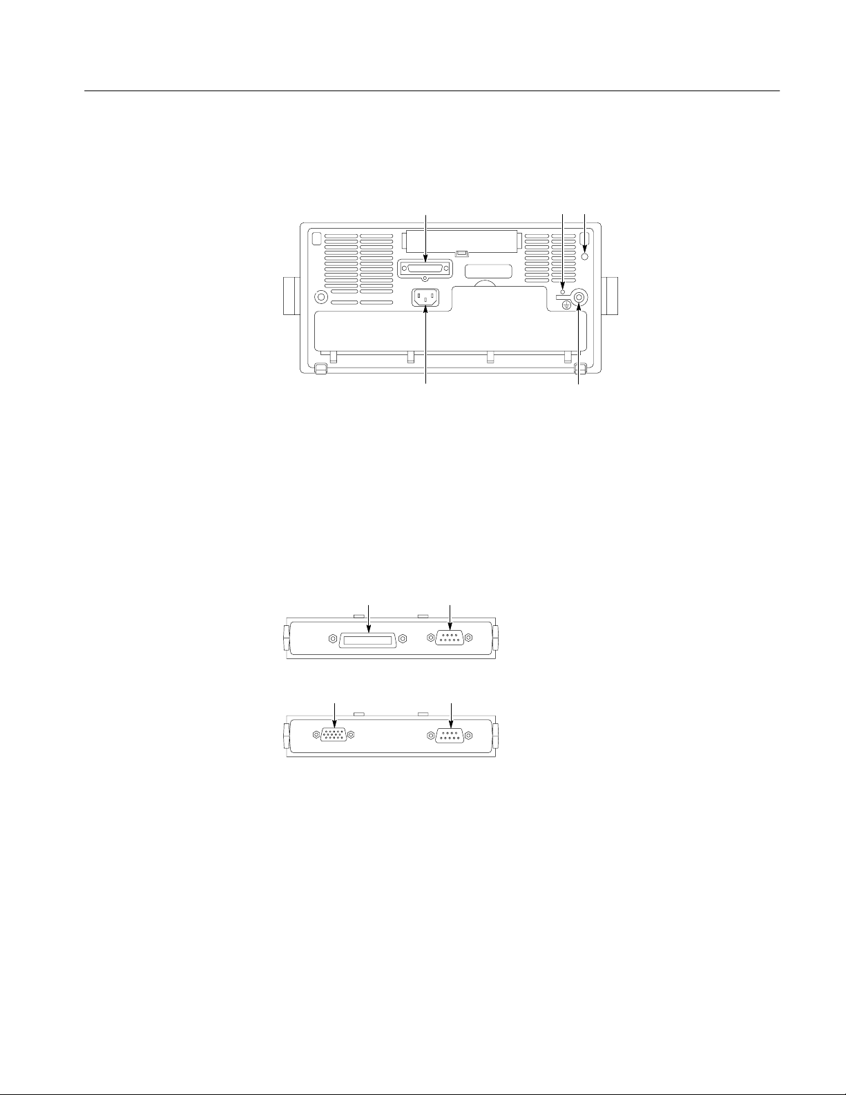
1. Parallel printer port. Connect to a printer to make hard copies.
2. CAL switch. For use by authorized service personnel only.
3. DC power output. Provides accessory power.
4. Ground terminal. Connect to earth ground when using battery power. See page 2–4 for
important safety information.
5. Power input. Attach to an AC power line with integral safety ground.
67
TDS3GM
2 3
6. GPIB port. Connect to a controller for remote programmability.
7. RS-232 port. Connect to a controller or terminal for remote programmability or
8. VGA port. Connect to a VGA monitor to display the screen image.
TDS3000 Series Service Manual
printing.
8 7
TDS3VM
2–19
Page 50

Operating Information
AUTOSET
Probe Compensation
Perform this adjustment to match your probe to the input channel. This should be
done whenever you attach a passive probe for the first time to any input channel.
1. Connect the oscilloscope probe to channel 1.
Attach the probe tip and reference lead to the
PROBE COMP connectors, then push AUTO-
SET.
If using the probe hook-tip, ensure a proper
connection by firmly twisting the tip onto the
probe.
2. Check the shape of the displayed waveform.
3. If necessary, adjust your probe.
Repeat as necessary.
PROBE COMP
CH 1
Overcompensated
Undercompensated
Compensated correctly
L
button
2–20
TDS3000 Series Service Manual
Page 51

Self Calibration
Operating Information
The self calibration routine lets you quickly optimize the oscilloscope signal path
for maximum measurement accuracy. You can run the routine anytime but you
should always run the routine if the ambient temperature changes by 10_ C or
more.
To compensate the signal path, do the following steps:
1. Disconnect any probes or cables from the channel input connectors.
2. Push the UTILITY button.
3. Push the System screen button to select Cal.
4. Push the Signal Path screen button.
5. Push OK Compensate Signal Path. This procedure takes several minutes to
complete.
NOTE. The signal path compensation does not include calibration to the probe
tip.
TDS3000 Series Service Manual
2–21
Page 52

Operating Information
2–22
TDS3000 Series Service Manual
Page 53

Theory of Operation
This chapter describes the electrical operation of the oscilloscope to the module
level. Figure 3–1 shows the oscilloscope module interconnections.
AC Line
Power supply
Fan
Battery
pack
J150
J100 J100
Battery
board
J170
J200
15 VDC external
device power
connector
Display
backlight
J950 J500
J900
Ch 1
Ch 1
Display
J860
comm. module
Main board
Attenuator circuit
Ch 2
Ch 2 Ch 3
J810
J700
J800
EXT
Ch 4
Parallel printer
connector
Front
panel
Floppy
Disk Drive
2-channel oscilloscopes
4-channel oscilloscopes
Input ports for
application
modules
Figure 3–1: TDS3000 series block diagram
Power Supply
The power supply converts AC line voltage to 15 VDC to power all internal
circuits and an external power connector. It also supplies power to charge the
optional battery pack.
TDS3000 Series Service Manual
3–1
Page 54

Theory of Operation
Battery Board
Main Board
The battery board provides the following functions:
H
Interfaces to the optional battery pack (powers the oscilloscope from the
battery pack or charges the battery pack when the oscilloscope is connected
to AC line).
H
Turns on AC power to the oscilloscope.
H
Converts 15 VDC from the power supply to 5 VDC for the main and front
panel boards and ±15 VDC for probe power.
H
Powers the cooling fan.
H
Routes 15 VDC from the power supply to the external power connector for
powering external devices.
Acquisition System
Trigger System
Display System
Processor System
The Main Board module contains the following functions.
The acquisition system begins with the analog signal path and ends with a
digitized signal in memory. The signal enters a channel input and then passes
through an attenuator and preamplifier. The analog signal from each preamplifier
goes through a sampler and digitizer, a time base controller, and then into
acquisition memory. The analog signal from each preamplifier is also distributed
to a trigger circuit.
The trigger system processes the analog signals from the preamplifiers and sends
trigger information to the time base controller. Advanced trigger functions are
enabled only when the appropriate application modules and supporting software
is installed.
The display system combines live waveform data from acquisition memory with
menus and text and stores this information in display memory. It then uses this
data to refresh the VGA display module (LCD).
The processor system contains a MPC680DC Power PC microprocessor that
controls the entire instrument. The processor system also contains flash ROM,
system RAM, and interfaces to communication modules, the parallel printer port,
and the floppy disk drive.
3–2
TDS3000 Series Service Manual
Page 55

Theory of Operation
Power Converter
Display Module
Front-Panel Board
Disk Drive
The power converter receives 15 VDC (or battery voltage) from the battery board
and generates voltages for the analog and digital circuitry on the main board.
The display module consists of a color liquid crystal display (LCD), a display
driver, a pair of fluorescent back light tubes, and a high-voltage back light power
supply.
The front-panel board contains a microprocessor that reads the front-panel
buttons and controls and then sends this information to the processor system.
The front-panel board also generates the probe compensation output signal and
provides an interface to the application modules.
The disk drive module consists of a 3.5 inch, IBM format, floppy disk drive. The
disk drive is controlled by circuitry on the Main Board.
TDS3000 Series Service Manual
3–3
Page 56

Theory of Operation
3–4
TDS3000 Series Service Manual
Page 57

Performance Verification
Wavetek 9500
Os
This chapter contains performance verification procedures for the specifications
marked with the n symbol. The following equipment, or a suitable equivalent,
is required to complete these procedures.
Description
DC Voltage Source 3 mV to 4 V , ±0.1% accuracy
Leveled Sine Wave Generator 50 kHz to 500 MHz, ±3%
Time Mark Generator 10 ms period, ±50 ppm accu-
You may need additional cables and adapters, depending on the actual test
equipment you use.
These procedures cover all TDS3000 oscilloscope models. Please disregard
checks that do not apply to the specific model you are testing.
Minimum
requirements
amplitude accuracy
racy
Examples
cilloscope Calibrator with
two 9510 Output Modules
Photocopy the test record on the next two pages and use them to record the
performance test results for your oscilloscope.
TDS3000 Series Service Manual
4–1
Page 58

Performance Verification
C
measureme
r
C
measureme
r
Test Record
Serial
number
Procedure performed by Date
Test Passed Failed
Self Test
Performance checks Low limit Test result High limit
hannel 1 DC
nt
accuracy
1 mV/div 99.25 mV 100.8 mV
2 mV/div
5 mV/div –101.8 mV –98.24 mV
–7.540 mV –6.460 mV
hannel 2 DC
accuracy
50 mV/div 982.4 mV 1.018 V
50 mV/div 632.4 mV 667.6 mV
50 mV delta 340.5 mV 359.5 mV
90 mV/div –339.3 mV –290.7 mV
200 mV/div 9.900 V 10.10 V
1 V/div –10.30 V –9.698 V
1 mV/div 99.25 mV 100.8 mV
nt
2 mV/div
5 mV/div –101.8 mV –98.24 mV
50 mV/div 982.4 mV 1.018 V
50 mV/div 632.4 mV 667.6 mV
50 mV delta 340.5 mV 359.5 mV
90 mV/div –339.3 mV –290.7 mV
200 mV/div 9.900 V 10.10 V
1 V/div –10.30 V –9.698 V
–7.540 mV –6.460 mV
4–2
TDS3000 Series Service Manual
Page 59

Performance checks High limitTest resultLow limit
C
measureme
r
C
measureme
r
C
C
C
C
hannel 3 DC
nt
accuracy
1 mV/div 99.25 mV 100.8 mV
2 mV/div
5 mV/div –101.8 mV –98.24 mV
50 mV/div 982.4 mV 1.018 V
50 mV/div 632.4 mV 667.6 mV
50 mV delta 340.5 mV 359.5 mV
90 mV/div –339.3 mV –290.7 mV
200 mV/div 9.900 V 10.10 V
1 V/div –10.30 V –9.698 V
–7.540 mV –6.460 mV
Performance Verification
hannel 4 DC
nt
accuracy
1 mV/div 99.25 mV 100.8 mV
2 mV/div
5 mV/div –101.8 mV –98.24 mV
50 mV/div 982.4 mV 1.018 V
50 mV/div 632.4 mV 667.6 mV
50 mV delta 340.5 mV 359.5 mV
90 mV/div –339.3 mV –290.7 mV
200 mV/div 9.900 V 10.10 V
1 V/div –10.30 V –9.698 V
–7.540 mV –6.460 mV
Channel 1 bandwidth 425 mV —
Channel 2 bandwidth 425 mV —
Channel 3 bandwidth 425 mV —
Channel 4 bandwidth 425 mV —
hannel 1
trigger sensitivity
hannel 2
trigger sensitivity
rising slope stable trigger —
falling slope stable trigger —
rising slope stable trigger —
falling slope
stable trigger —
TDS3000 Series Service Manual
hannel 3
trigger sensitivity
hannel 4
trigger sensitivity
rising slope stable trigger —
falling slope stable trigger —
rising slope stable trigger —
falling slope stable trigger —
Sample rate and delay time accuracy –2 divisions +2 divisions
4–3
Page 60

Performance Verification
Performance V erification Procedures
Before beginning these procedures, two conditions must first be met:
H
The oscilloscope must have been operating continuously for ten minutes in
an environment the meets the operating range specifications for temperature
and humidity.
H
You must perform the Compensate Signal Path operation described on page
2–21. If the operating temperature changes by more than 10° C, you must
perform the Compensate Signal Path operation again.
The time required to complete the entire procedure is approximately one hour.
WARNING. Some procedures use hazardous voltages. To prevent electrical shock,
always set voltage source outputs to 0 V before making or changing any
interconnections.
Self Test
This procedure uses internal routines to verify that the oscilloscope functions and
passes its internal self tests. No test equipment or hookups are required. Start the
self test with these steps:
1. Disconnect all probes and cables from the oscilloscope inputs.
2. Push the UTILITY menu button.
3. Push the System screen button to select Diags.
4. Push the Loop screen button and choose Once.
5. Push the Execute screen button.
6. Push the OK Confirm Run Test screen button.
A dialog box displays the result when the self test completes. Push the MENU
OFF screen button to continue operation.
4–4
TDS3000 Series Service Manual
Page 61

Performance Verification
Check DC Voltage
Measurement Accuracy
This test checks the DC voltage measurement accuracy in the average acquisition
mode.
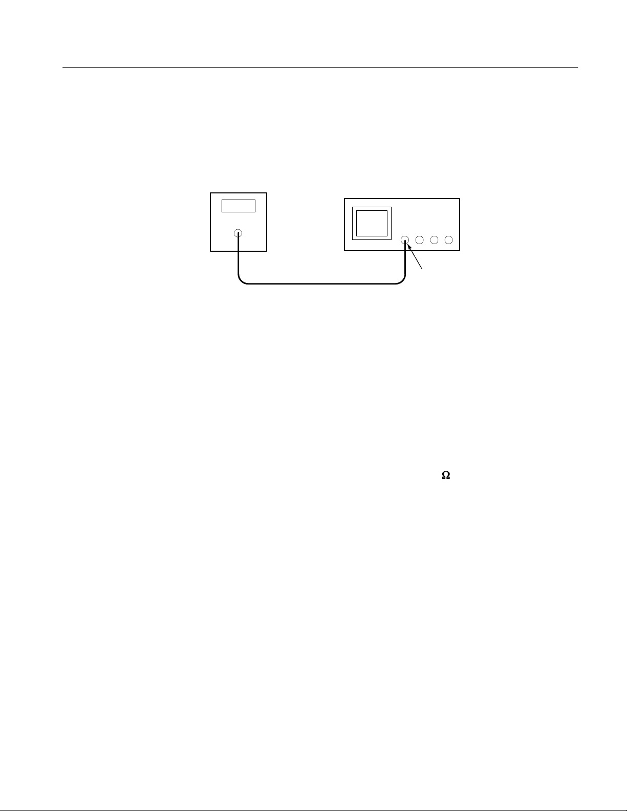
1. Set the DC voltage source output level to 0 V.
2. Connect the DC voltage source to the oscilloscope channel 1 input as shown
below.
DC voltage
source
TDS3000 Series Oscilloscope
Ch 1
3. Push the SAVE/RECALL menu button.
4. Push the Recall Factory Setup screen button and then push the OK
Confirm Factory Init screen button.
5. Push the acquire MENU button.
6. Push the Mode screen button and then push the Average screen button.
7. Adjust the number of averages to 16 with the general purpose knob.
8. Skip to step 11.
9. Move the DC voltage source output cable to the oscilloscope channel you
want to check.
10. Push the channel button (CH 1, CH 2, CH 3, or CH 4) for the channel you
want to check.
11. Push the MEASURE menu button.
12. Push the Select Measurement screen button.
13. Push the –more– screen button until you can select the Mean measure-
ment.
14. Push the vertical MENU button.
TDS3000 Series Service Manual
4–5
Page 62

Performance Verification
Vertical SCALE
setting
1 mV/div Off 20 MHz 96.5 mV 100 mV 99.25 mV 100.8 mV
2 mV/div Off 20 MHz 0.0 V –7 mV –7.540 mV –6.460 mV
5 mV/div Off 20 MHz –82.5 mV –100 mV –101.8 mV –98.24 mV
50 mV/div Off Full 825 mV 1.0 V 982.4 mV 1.018 V
50 mV/div Off Full 825 mV 650 mV 632.4 mV 667.6 mV
50 mV
1
delta
90 mV/div
200 mV/div Off 150 MHz
1 V/div On
1
2
2
Refer to step 15e on page 4–6 to calculate 50 mV delta measurement.
Push the Vertical MENU button, push the Fine Scale screen button, then use the general purpose knob to adjust setting to
Invert
setting
Off Full 0.0 V –315 mV –339.3 mV –290.7 mV
4
Bandwidth limit
setting
3
150 MHz
3
Input
Offset
9.3 V 10 V 9.900 V 10.10 V
–6.5 V 10 V –10.30 V –9.698 V
voltage
Low
limit
340.5 mV 359.5 mV
High
limit
90 mV/div.
3
Use the Full bandwidth setting on the TDS3012 or TDS3014 oscilloscopes.
4
Make sure to turn Invert setting to On for this measurement.
15. For each row of the table, do these steps:
a. Set the vertical SCALE control to the setting in the table.
b. Set the Invert and Bandwidth Limit controls to the settings in the table.
c. Set the output of the DC voltage source to the voltage level in the table.
Verify that the oscilloscope Mean measurement is within the limits listed in
d.
the above table.
e. For the 50 mV delta measurement, subtract the second 50 mV measurement
from the first 50 mV measurement; verify that the difference is within the
limits stated in the Delta row of the table.
16. Repeat steps 15a through 15e for each row in the table.
17. Push the waveform off
button.
18. Repeat steps 9 through 17 for each channel of the oscilloscope (not including
the external trigger input on some models).
4–6
TDS3000 Series Service Manual
Page 63

Performance Verification
Check Bandwidth
This test checks the bandwidth for each channel.
1. Connect the output of the leveled sine wave generator to the oscilloscope
channel 1 input as shown below.
Leveled sine
wave generator
TDS3000 Series Oscilloscope
Ch 1
2. Push the SAVE/RECALL menu button.
3. Push the Recall Factory Setup screen button and then push the OK
Confirm Factory Init screen button.
4. Push the acquire MENU button.
5. Push the Mode screen button and then push the Average screen button.
6. Adjust the number of averages to 16 with the general purpose knob.
7. Push the trigger MENU button.
8. Push the Source screen button and then push the Vert screen button.
9. Push the Coupling screen button and then push the Noise Reject screen
button.
10. Skip to step 13.
11. Move the output cable of the leveled sine wave generator to the oscilloscope
channel you want to check.
12. Push the channel button (CH 1, CH 2, CH 3, or CH 4) for the channel you
want to check.
13. Set the horizontal SCALE to 10 ms/div.
14. Push the vertical MENU button.
15. Push the Coupling screen button and select 50 W input resistance.
16. Push the MEASURE menu button.
17. Push the Select Measurement screen button.
TDS3000 Series Service Manual
4–7
Page 64

Performance Verification
18. Push the –more– screen button until you can select the Pk-Pk measure-
ment.
19. Set the vertical SCALE to 100 mV/div.
20. Set the output frequency of the leveled sine wave generator to 50 kHz.
21. Set the output amplitude of the leveled sine wave generator so the peak-to-
peak measurement is between 599 mV and 601 mV.
22. Set the horizontal SCALE to 10 ns/div.
23. Set the output frequency of the leveled sine wave generator to the frequency
shown in the table below.
Oscilloscope model Frequency
TDS3012, TDS3014 100 MHz
TDS3032, TDS3034 300 MHz
TDS3052, TDS3054 500 MHz
24. Verify that the peak-to-peak measurement is ≥425 mV.
25. Push the waveform off
button.
26. Repeat steps 11 through 25 for each channel of the oscilloscope (not
including the external trigger input on some models).
4–8
TDS3000 Series Service Manual
Page 65

Performance Verification
Check Channel
Edge-Trigger Sensitivity
This test checks the edge-trigger sensitivity for each channel.
1. Connect the output of the leveled sine wave generator to the oscilloscope
channel 1 input as shown below.
Leveled sine
wave generator
TDS3000 Series Oscilloscope
Ch 1
2. Push the SAVE/RECALL menu button.
3. Push the Recall Factory Setup screen button and then push the OK
Confirm Factory Init screen button.
4. Push the acquire MENU button.
5. Push the Mode screen button and then push the Average screen button.
6. Adjust the number of averages to 16 with the general purpose knob.
7. Push the trigger MENU button.
8. Push the Source screen button and then push the Vert screen button.
9. Set the horizontal SCALE to 10 ns/div.
10. Skip to step 13.
11. Move the output cable of the leveled sine wave generator to the oscilloscope
channel you want to check.
12. Push the channel button (CH 1, CH 2, CH 3, or CH 4) for the channel you
want to check.
13. Push the vertical MENU button.
14. Push the Coupling screen button and select 50 W input resistance.
15. Push the MEASURE menu button.
16. Push the Select Measurement screen button.
17. Push the –more– screen button until you can select the Pk-Pk measure-
ment.
TDS3000 Series Service Manual
18. Set the vertical SCALE to 500 mV/div.
4–9
Page 66

Performance Verification
19. Set the output frequency of the leveled sine wave generator to the frequency
shown in the table below.
Oscilloscope model Frequency
TDS3012, TDS3014 100 MHz
TDS3032, TDS3034 300 MHz
TDS3052, TDS3054 500 MHz
20. Set the output amplitude of the leveled sine wave generator so the peak-topeak measurement is approximately 500 mV.
21. Push the SET TO 50% button. Adjust the trigger LEVEL as necessary and
then verify that triggering is stable.
22. Push the trigger MENU button.
23. Push the Slope screen button and select the \ (falling) slope.
24. Push the SET TO 50% button. Adjust the trigger LEVEL as necessary and
then verify that triggering is stable.
25. Push the Slope screen button and select the / (rising) slope.
26. Push the waveform off
button.
27. Repeat steps 11 through 26 for each channel of the oscilloscope (not
including the external trigger input on some models).
4–10
TDS3000 Series Service Manual
Page 67
Performance Verification
Check Sample Rate and
Delay Time Accuracy
This test checks the time base accuracy.
1. Connect the output of the leveled sine wave generator to the oscilloscope
channel 1 input as shown below.
Time mark
generator
TDS3000 Series Oscilloscope
Ch 1
2. Push the SAVE/RECALL menu button.
3. Push the Recall Factory Setup screen button and then push the OK
Confirm Factory Init screen button.
4. Set the time mark generator period to 10 ms. Use a time mark waveform
with a fast rising edge.
5. If adjustable, set the time mark amplitude to approximately 1 V
p-p
.
6. Push the DELAY button to turn delay off.
7. Push the vertical MENU button.
8. Push the Coupling screen button and select 50 W input resistance.
9. Set the vertical SCALE to 500 mV/div.
10. Set the horizontal SCALE to 2 ms/div.
11. Adjust the vertical POSITION control to center the time mark signal on the
screen.
12. Adjust the trigger LEVEL as necessary to obtain a triggered display.
13. Adjust the horizontal POSITION control to move the trigger location to the
center of the screen (50%).
14. Push the DELAY button to turn delay on.
TDS3000 Series Service Manual
4–11
Page 68

Performance Verification
15. Turn the horizontal POSITION control counter-clockwise to set the delay to
exactly 10 ms.
16. Set the horizontal scale to 1 ms/div.
17. Check that the rising edge of the marker crosses the center horizontal
graticule line within ±2 divisions of center graticule.
NOTE. One division of displacement from graticule center corresponds to a 100
ppm time base error.
This completes the performance verification procedure.
4–12
TDS3000 Series Service Manual
Page 69

Adjustment Procedures
Wavetek 9500 Os
pe
Outp
e
This chapter contains the factory adjustment procedures for the oscilloscope.
Only qualified personnel should perform service procedures. Read this Service
Safety Summary and the General Safety Summary before performing any service
procedures. Also refer to the chapter Operating Information for information
about using the oscilloscope.
NOTE. The voltage references inside the oscilloscope are very stable over time
and should not require routine adjustment. Before performing any procedure in
this chapter, first verify that the oscilloscope does not meet specifications. Refer
to the chapter Performance Verification for procedures to verify the specifica-
tions.
Required Equipment
The following equipment, or a suitable equivalent, is required to complete these
procedures.
Minimum
Description
DC voltage source 50 mV to 50 V, ±0.1% ampli-
Leveled sine wave generator 30 kHz to 50 MHz, 100 ppm
Fast-rise generator 1 MHz repetition rate, 1 V
50 W BNC cable
(five required 1)
BNC T (three required 1) One male and two female
BNC female-to-female adapter Two female BNC connectors Tektronix part number
Adjustment tool Non conducting shaft with
1
The number required is reduced by two if you are adjusting a two-channel
oscilloscope.
requirements
tude accuracy
frequency accuracy, 3% amplitude accuracy
Pk-Pk signal, ≤1 ns rise time
BNC male to BNC male,
≈ 10 in (25 cm) long
BNC connectors
diameter ≤2.5 mm (≤0.1 in)
Example
cillosco
Calibrator with one 9510
ut Modul
Tektronix part number
012-0208-00
Tektronix part number
103-0030-00
103-0028-00
Tektronix part number
003-1433-00
TDS3000 Series Service Manual
5–1
Page 70

Adjustment Procedures
Overview of the Adjustment Process
The oscilloscope is protected from inadvertently changing factory adjustments
by a rear-panel switch. To perform the factory adjustment, you must push and
hold the switch while you power on the oscilloscope.
Before performing adjustment procedures, you must warm up the oscilloscope at
least ten minutes in an ambient temperature between 20° C and 30° C. Adjustments performed prior to warm-up or outside this temperature range may result
in poor performance.
The factory adjustment procedure consists of a series of steps; as you move
through these steps, the oscilloscope display provides instructions that describe
the specific input signal requirements for each step. If the the step passes, the
oscilloscope moves on to the next step. If any step fails, you can repeat the step
or choose to abort the procedure.
NOTE. During some steps, the instrument may appear to be idle for several
minutes while it is processing information internally. Please have patience.
If all steps in the procedure are completed successfully, a “Pass” message is
displayed and the new calibration constants take affect. If the procedure fails for
any reason, the oscilloscope reverts to the previous calibration settings.
5–2
TDS3000 Series Service Manual
Page 71

Signal Connections
Adjustment Procedures
The adjustment procedure requires three types of equipment setups if you are
adjusting a four-channel oscilloscope, or four types if you are adjusting a
two-channel oscilloscope. For each step of the procedure, the oscilloscope
display indicates which setup is the correct one to use. The equipment setups are
described below.
Apply DC Voltage to
Channels
The first steps require a DC voltage (or zero volts) to be applied simultaneously
to all the channels. A typical on-screen instruction might read:
Apply 0.0000 V DC signal to all channels.
When you see an instruction similar to this, connect the oscilloscope to the DC
voltage source to all the channels as shown below and then set the DC voltage to
the specified value.
DC voltage
source
DC voltage
source
Four-channel TDS3000
Series Oscilloscope
Equal-length
BNC cables
BNC tees
Two-channel TDS3000 Series
Oscilloscope
TDS3000 Series Service Manual
Equal-length
BNC cables
BNC tee
5–3
Page 72

Adjustment Procedures
NOTE. If the DC voltage source you are using has an output head, use a
female-to-female BNC adapter and a short BNC cable to make the connection to
the first BNC tee.
When you are given the instruction to apply a 0 V DC signal, turn off or ground
the output of the DC voltage source to be sure that no DC voltage is present.
Apply Pk-Pk Voltage to a
Channel
Later in the procedure, a leveled sine wave needs to be applied to each channel,
one channel at a time. A typical on-screen instruction might read:
Apply 400.00 mV PkĆPk sine wave signal to channel 1 only.
When you see an instruction similar to this, connect the leveled sine wave
generator to the specified channel and then set the amplitude and frequency to
the specified values.
Leveled sine
wave generator
TDS3000 Series Oscilloscope
Ch 1
NOTE. If the leveled sine wave generator you are using has an output head,
connect the head directly to the channel input.
Make sure that the AC generator output is set for a 50-ohm load for all
AC-source steps.
5–4
TDS3000 Series Service Manual
Page 73

Adjustment Procedures
Apply Fast Rise Step
Signal to all Channels
Apply DC Voltage to
External Trigger
During the procedure a fast rise step signal needs to be applied simultaneously to
all channels. A typical on-screen instruction might read:
Apply 1.000 V PkĆPk fastĆrise signal to all channels.
Use the ’Apply DC Voltage to Channels’ equipment setup shown on page 5–3.
NOTE. Make sure that the coax cable connection path length is the same for all
channels.
The fast-rise signal Pk-Pk range is -1 V to 0 V.
Make sure to set the generator output load to 50 ohms.
If you are adjusting a two-channel oscilloscope, a DC voltage needs to be
applied to the external trigger input. A typical on-screen instruction might read:
Apply -5.00 V DC signal to external trigger input.
When you see an instruction similar to this, connect the oscilloscope to the DC
voltage source and set the DC voltage to the specified value.
DC voltage
source
TDS3000 Series Oscilloscope
Ext Trig
NOTE. If the DC voltage source you are using has an output head, connect the
head directly to the external trigger input.
TDS3000 Series Service Manual
5–5
Page 74

Adjustment Procedures
Factory Adjustment Procedure
To perform the factory adjustment procedure, do these steps:
1. Locate the hole that provides access to the CAL switch on the rear panel.
2. Put the adjustment tool into the CAL switch hole. Push and hold the CAL
switch in while you power on the oscilloscope. Release the switch when the
oscilloscope shows the power-on message with the oscilloscope graticule in
the background.
CAL
3. Push the SAVE/RECALL button.
4. Push the Recall Factory Setup screen button.
5. Push the OK Confirm Factory Init screen button to restore factory settings
prior to doing the factory calibration.
6. Push the MENU OFF button.
7. Push the UTILITY button.
8. Push the System screen button to select Cal.
9. Push the Factory screen button.
10. Push the OK Do Factory Calibration screen button to start the adjustment
process.
5–6
TDS3000 Series Service Manual
Page 75

Adjustment Procedures
11. Connect signals from the DC voltage source, leveled sine wave, or fast-rise
generator as instructed by the oscilloscope display. After you connect the
correct signal, push the OK Do Next Step screen button to continue the
process.
NOTE. The oscilloscope adjusts itself automatically using the reference signal
from the DC voltage source, leveled sine wave, or fast-rise generator. There are
no manual oscilloscope adjustments that you need to make.
If you make an error, such as connecting the wrong input signal, you can repeat
the last step by pushing the Return to Previous Screen screen button.
12. Continue the adjustment process until it is complete. You can abort the
process at any time by pushing the MENU OFF button or by changing to a
different menu.
TDS3000 Series Service Manual
5–7
Page 76

Adjustment Procedures
5–8
TDS3000 Series Service Manual
Page 77

Maintenance
This chapter contains the information needed to do periodic and corrective
maintenance on the oscilloscope. The following sections are included:
H
Preparation refers you to important information contained elsewhere in this
manual.
H
Preventing ESD provides general information on preventing damage to
internal modules when doing maintenance.
H
Inspection and Cleaning provides procedures for inspecting the oscilloscope
and cleaning its external and internal modules.
H
Removal and Installation Procedures provide procedures for the removal and
installation of modules.
H
Troubleshooting provides information for isolating failed modules.
H
Unpacking and Repacking Instructions provides packaging information for
shipment or storage.
Preparation
Preventing ESD
Only qualified personnel should perform service procedures. Read the Service
Safety Summary and the General Safety Summary before performing any service
procedures. Also refer to the chapter Operating Information for information
about using the oscilloscope.
When performing any service which requires internal access to the oscilloscope,
adhere to the following precautions to avoid damaging internal modules and their
components due to electrostatic discharge (ESD).
CAUTION. Static discharge can damage any semiconductor component in this
instrument.
1. Minimize handling of static-sensitive modules.
2. Transport and store static-sensitive modules in their static protected
containers or on a metal rail. Label any package that contains static-sensitive
modules.
TDS3000 Series Service Manual
6–1
Page 78

Maintenance
Inspection and Cleaning
3. Discharge the static voltage from your body by wearing a grounded antistatic
wrist strap while handling these modules. Do service of static-sensitive
modules only at a static-free work station.
4. Nothing capable of generating or holding a static charge should be allowed
on the work station surface.
5. Handle circuit boards by the edges when possible.
6. Do not slide the modules over any surface.
7. Avoid handling modules in areas that have a floor or work-surface covering
capable of generating a static charge.
This section describes how to inspect for dirt and damage, and how to clean the
oscilloscope. Inspection and cleaning are done as preventive maintenance.
Preventive maintenance, when done regularly, may prevent malfunctions and
enhance reliability.
General Care
Inspection and Cleaning
Procedures
Preventive maintenance consists of visually inspecting and cleaning the
oscilloscope, and using general care when operating it. How often to do
maintenance depends on the severity of the environment in which the oscilloscope is used. A proper time to perform preventive maintenance is just before
adjustment of the oscilloscope.
Protect the oscilloscope from adverse weather conditions. The oscilloscope is not
waterproof.
Do not store or leave the oscilloscope where the LCD display will be exposed to
direct sunlight for long periods of time.
CAUTION. To avoid damage to the oscilloscope, do not expose it to any sprays,
liquids, or solvents.
Inspect and clean the oscilloscope as often as operating conditions require. The
collection of dirt on internal components can cause them to overheat and
breakdown. Dirt acts as an insulating blanket, preventing efficient heat dissipation. Dirt also provides an electrical conduction path
oscilloscope failure, especially under high-humidity conditions.
that could cause an
6–2
TDS3000 Series Service Manual
Page 79

Maintenance
Inspection — Exterior. Inspect the outside of the oscilloscope for damage, wear,
and missing parts. An oscilloscope that appears to have been dropped or
otherwise abused should be checked thoroughly to verify correct operation and
performance. Immediately repair defects that could cause personal injury or lead
to further damage to the oscilloscope.
Cleaning Procedure — Exterior. To clean the oscilloscope exterior, perform the
following steps:
1. Remove loose dust on the outside of the oscilloscope with a lint free cloth.
Use care to avoid scratching the clear plastic display filter.
2. Use a soft cloth or paper towel dampened with water to clean the oscilloscope. You can use a 75% isopropyl alcohol solution for more efficient
cleaning.
CAUTION. To avoid damage to the surface of the oscilloscope, do not use any
abrasive or chemical cleaning agents.
Inspection — Interior. During normal use, the oscilloscope case protects the
internal components against common dust and dirt. However, if it appears that
the oscilloscope may have been damaged or has been exposed to an unusually
dirty or wet environment, you should inspect and clean the interior.
To inspect and clean the interior, disassemble the oscilloscope according to the
procedure Removal and Installation Procedures on page 6–5.
Inspect the internal portions of the oscilloscope for damage and wear using
Table 6–1 as a guide. Defects found should be repaired immediately.
T able 6–1: Internal inspection check list
Item Inspect for Repair action
Front and Rear Case
Cover
Metal chassis pieces Bent, fractured, or broken pieces. Repair or replace defective hard-
Circuit boards Loose, broken, or corroded solder
Cracks or deformations. Broken
doors or hinges. Loose labels.
connections. Burned circuit
boards. Burned, broken, or
cracked circuit-run plating.
Repair or replace defective hardware.
ware.
Remove failed module and replace
with a new module.
TDS3000 Series Service Manual
6–3
Page 80

Maintenance
T able 6–1: Internal inspection check list (Cont.)
Item Repair actionInspect for
Solder connections Cold solder or rosin joints. Resolder joint and clean with
isopropyl alcohol.
Wiring and cables Loose plugs or connectors.
Burned, broken, or frayed wiring.
Firmly seat connectors. Repair or
replace modules with defective
wires or cables.
Cleaning Procedure — Interior. To clean the oscilloscope interior, perform the
following steps:
1. Blow off dust with dry, low-pressure, deionized air (approximately 9 psi).
2. Remove any remaining dust with a lint-free cloth dampened in isopropyl
alcohol (75% solution) and rinse with warm deionized water. (A cottontipped applicator is useful for cleaning in narrow spaces and on circuit
boards.)
STOP. If, after performing steps 1 and 2, a module is clean upon inspection, skip
steps 3 and 4. Proceed with step 5.
If steps 1 and 2 do not remove all the dust or dirt, all modules in the oscilloscope
except the Display Module, Fan, and Disk Drive may be spray washed using a
solution of 75% isopropyl alcohol. Proceed with step 3.
3. Spray wash dirty parts with the 75% isopropyl alcohol solution and wait
60 seconds for the majority of the alcohol to evaporate.
6–4
4. Use hot (49_ C to 60_ C / 120_ F to 140_ F) deionized water to thoroughly
rinse the parts.
5. Dry all parts with low-pressure, deionized air.
6. Dry all components and assemblies in an oven or drying compartment using
low-temperature (52_ C to 66_ C / 125_ F to 150_ F) circulating air.
Lubrication. There is no periodic lubrication required for the oscilloscope.
TDS3000 Series Service Manual
Page 81

Removal and Installation Procedures
This section describes how to remove and install the major mechanical and
electrical modules. It provides the following information:
H
List of Modules on page 6–5 describes where to locate a list of replaceable
modules.
H
Summary of Procedures on page 6–6 lists the procedures for removal and
installation of modules.
H
Tools Required on page 6–7 describes the tools needed to perform the
procedures.
H
Handle, on page 6–7, begins a series of procedures that describe the
removal and installation of modules.
Maintenance
Preparation
List of Modules
Please read the following warning statement. Then read the following general
instructions before removing a module.
WARNING. Only qualified personnel should perform service procedures. Before
doing this or any other procedure in this manual, read the General Safety
Summary and Service Safety Summary located at the beginning of this manual.
Also, to prevent possible injury to service personnel or damage to electrical
components, read Preventing ESD on page ix.
1. Read the Summary of Procedures on page 6–6 to understand which
procedure to use to access a given module. Then read Tools Required on
page 6–7 for a list of tools needed to remove and install modules in the
oscilloscope.
2. If you are disassembling the oscilloscope for cleaning, refer to the Inspection
and Cleaning procedure on page 6–2 for cleaning instructions.
3. Remove the optional battery pack and/or communication module before
disassembling the oscilloscope.
The Mechanical Parts List chapter provides a list of all replaceable modules.
Any electrical or mechanical module, assembly, or part listed in the parts list is
referred to as a module.
TDS3000 Series Service Manual
6–5
Page 82

Maintenance
Summary of Procedures
Table 6–2 lists the removal and installation procedures in order of increasing
complexity. Within each procedure, only perform the steps that are required to
access the modules that need repair.
T able 6–2: Removal and installation procedures
Procedure Modules accessed Begins on page
Handle Handle
Hub cover
Hub assembly
Rear case Rear case
Communication module cover
Communication module guide
Feet
Disk drive
Rear chassis Rear chassis
Battery board
Power supply
Power supply bracket
Line filter
DC power cable
AC line power cable
Fan
Parallel printer port
External power jack
Main board Main board
Display cable
Disk drive cable
Front chassis and display
Module
Front chassis
Display module
Inverter cable
Inverter board
Display module
6–7
6–1 1
6–15
6–20
6–23
6–6
Display Inverter board
and backlights
Front panel Knobs
Inverter board
Backlight tubes
Front-panel board
Flex circuit keypad contacts
Keypads
6–26
6–31
TDS3000 Series Service Manual
Page 83

Maintenance
Tools Required
Handle
You will need the following tools to remove and replace all the modules in the
oscilloscope.
H
Torque-limiting screwdriver, 12 in ⋅ lb (1.3 N ⋅ m) range with Torx T-10
and T-15 tips (If you are using a magnetic screwdriver with interchangeable
bits, the T-15 bit must be a long bit, at least 5 cm (2 in) overall length).
1
H
Screwdriver with
3
H
@16 inch nut driver
H
Needle-nose pliers
You will need a
@8 inch flat blade
1
@8 inch flat-bladed screwdriver to remove the handle.
Removal. Use this procedure to remove the handle.
1
1. Use the
@8 inch flat-bladed screwdriver to pry the hub cover off of each side
of the handle.
2. Raise the handle to its full upright position.
3. Locate the handle hub on the display side of the oscilloscope.
NOTE. Do not remove the screw at the center of the handle hub.
4. Use the needle-nose pliers to pull the metal pin in the display-side hub
outward approximately 5 mm (0.2 in). If you accidentally pull the metal pin
all the way out, reinsert it half way. See Figure 6–1.
TDS3000 Series Service Manual
6–7
Page 84

Maintenance
Handle
Hub
Metal pin
Figure 6–1: Pulling the hub pin
5. Place the oscilloscope on its feet on soft surface (such as an anti-static mat),
with the display-side hub facing you.
6. Lower the handle toward the rear into a horizontal position. The hub should
rotate with the handle.
7. Pull outward on the handle at the hub to release the display-side hub
assembly. You may need to rotate the handle back and forth slightly to help
release the hub assembly. See Figure 6–2.
6–8
TDS3000 Series Service Manual
Page 85

Rotate the handle
Maintenance
Pull on the handle
Hub
Figure 6–2: Releasing the hub assembly
8. Locate the remaining hub on the opposite side of the oscilloscope. Place the
oscilloscope with the remaining hub facing you.
9. Rotate the handle downward to its lowest position.
10. Use the needle-nose pliers to pull the metal pin in the remaining hub outward
approximately 5 mm (0.2 in).
TDS3000 Series Service Manual
6–9
Page 86

Maintenance
11. Raise the handle to its full upright position. The hub should rotate with the
handle.
12. Pull outward on the handle to release the remaining hub assembly. You may
need to rotate the handle back and forth slightly to help release the hub
assembly.
13. Grasp the handle from both sides and remove it from the oscilloscope.
Installation. Use this procedure to reinstall the handle.
1. Place the oscilloscope on its feet on soft surface (such as an anti-static mat),
with the front facing you.
2. Verify that the front and rear cases fit together tightly.
3. Grasp the handle from both sides and stretch it over the over the top of the
oscilloscope. Rotate the handle into its full upright position. The Tektronix
logo should appear right-side up when looking down on the handle.
4. Insert one hub assembly into the handle on the right side (non display side)
of the oscilloscope. The hub assembly can go in one of two ways, 180°
apart; either way is ok.
5. While pressing in on the hub assembly with your fingers, rotate the handle
away from you into its lowest position. The hub assembly should rotate with
the handle.
1
6. Use the
@8 inch flat-bladed screwdriver to push the metal pin in to lock the
hub assembly. Once locked, the hub assembly should not rotate when you
rotate the handle.
7. With the handle in its lowest position, insert the remaining hub assembly
into the handle on the display side of the oscilloscope.
6–10
TDS3000 Series Service Manual
Page 87

Maintenance
8. While pressing in on the hub assembly with your fingers, rotate the handle to
its full upright position. The hub assembly should rotate with the handle.
9. Use the
1
@8 inch flat-bladed screwdriver to push the metal pin in to lock the
hub assembly.
10. Verify that both hub assemblies do not rotate when you rotate the handle.
11. Snap the hub covers into place over the hub assemblies. See Figure 6–3.
Hub cover
Figure 6–3: Reinstalling a hub cover
Rear Case
You will need a Torx T-15 screwdriver to remove the rear case.
Removal. Use this procedure to remove the rear case, feet, communication
module cover, communication module guide, and disk drive.
NOTE. You must remove the handle assembly before you can remove the rear
case. Follow the procedure on page 6–7 to remove the handle.
1. Place the oscilloscope face down on soft surface (such as an anti-static mat),
with the bottom facing you.
2. Remove the screw just below the parallel printer port.
3. Remove the communication module cover or any communication module
that may be installed.
4. Lift the rear cover off of the oscilloscope chassis.
5. Remove both feet if necessary to replace them, otherwise leave the feet
installed in the back cabinet.
TDS3000 Series Service Manual
6–11
Page 88

Maintenance
6. Release the small communication module guide tab by lifting the chassis,
and then remove the communication module guide. See Figure 6–4.
Tab
Communication
module guide
6–12
Figure 6–4: Communication module guide
7. Carefully open the connector that captures the disk drive flex cable and
disconnect the flex cable from the disk drive. See Figure 6–5.
8. Lift the disk drive out of the oscilloscope chassis.
TDS3000 Series Service Manual
Page 89

Disk drive
Maintenance
Pins are face
down
Figure 6–5: Flex cable to the disk drive
Installation. Use this procedure to install the disk drive, communication module
guide, feet, rear case, and communication module cover.
1. Place the oscilloscope face down on soft surface (such as an anti-static mat),
with the bottom facing you.
2. Install the communication module guide into the chassis. Lift the chassis and
insert the small tab in the chassis slot. See Figure 6–4.
3. Install the feet into the front case if you removed them in a previous step.
4. Place the disk drive into its cavity in the chassis. The flex cable should align
with its connector on the disk drive.
NOTE. If you are installing a new disk drive, remove the plastic bezel from the
new disk drive and discard the bezel. See Figure 6–6.
TDS3000 Series Service Manual
6–13
Page 90
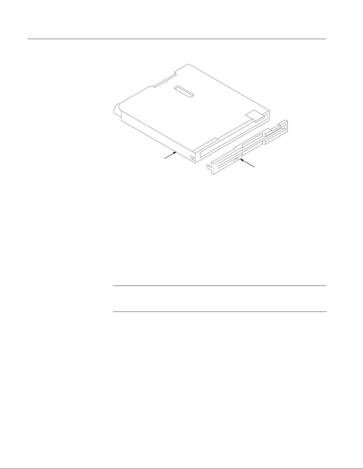
Maintenance
Disk drive
Bezel
Figure 6–6: Removing the bezel from a new disk drive
5. Carefully open the connector on the disk drive, insert the flex connector, and
then close the connector. See Figure 6–5.
6. Place the rear case over the oscilloscope chassis and lower it. Be sure that the
disk drive is captured inside the case and does not slip from its correct
position. The rear case should fit over and capture the feet.
7. Press the rear case downward so that it is seated completely.
8. Install the screw below the parallel port connector.
NOTE. The screw installed below the parallel printer connector is 0.25 inches
long. Make sure you use the correct-length screw when attaching the rear
cabinet to the rear chassis.
9. Install the communication module cover or a communication module.
6–14
TDS3000 Series Service Manual
Page 91
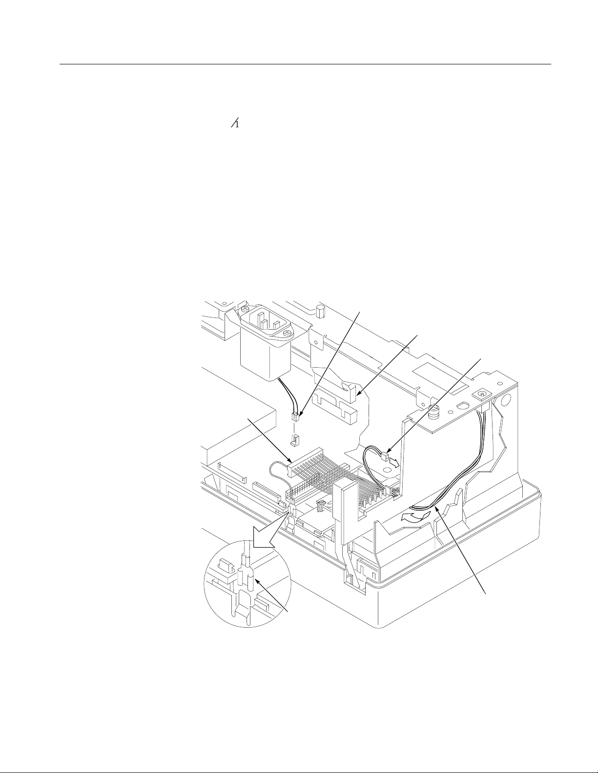
Maintenance
Rear Chassis
You will need a Torx T-15 screwdriver to remove the rear chassis. You will
need a
3
@16 inch nut driver to remove the parallel printer port cable.
Removal. Use this procedure to remove the rear chassis, battery board, external
power jack, power supply, power supply bracket, line filter, fan, and parallel
printer port cable.
1. Place the oscilloscope face down on soft surface (such as an anti-static mat),
with the bottom facing you.
2. Disconnect the parallel port ribbon cable, line trigger cable, and DC power
cable from the main board. Disconnect the spade connector on the DC power
cable from the tab on the chassis, making sure not to pull on the wire coming
out of the DC power connector. See Figure 6–7.
Line trigger cable to J980
Parallel port ribbon cable to J810
External power cable to J200
DC power
connector
DC power spade
connector
Figure 6–7: Cables to the main board
Cable routes under
battery board
TDS3000 Series Service Manual
6–15
Page 92

Maintenance
3. Disconnect the external power cable from the battery board. See Figure 6–7.
4. Remove the three screws that secure the rear chassis to the front chassis.
5. Lift the rear chassis assembly from the front chassis. Thread the external
power cable through the hole in the front chassis.
STOP. If you do not need to disassemble the rear chassis assembly, skip to the
next procedure, Main Board, on page 6–20. The following instructions describe
complete disassembly of the rear chassis assembly. However, you can just
remove the modules from the rear chassis that appear to be in the way of the
module you need to access.
6. Remove the power switch extension from the power switch.
7. Disconnect the 18-pin DC power cable from the battery board. You can use
1
the
@8 inch flat-bladed screwdriver to help pry it loose.
8. Remove the two screws that secure the battery board to the rear chassis.
1
9. Disconnect the fan cable from the battery board. You can use the
@8 inch
flat-bladed screwdriver to help undo the connection.
10. Unsnap the battery board from the rear chassis. You can use the
1
@8 inch
flat-bladed screwdriver to help release the board from the snap post.
11. Disconnect the AC line power cable from the power supply.
12. Remove the DC power cable from the power supply.
13. Remove the two screws that secure the power supply to the rear chassis.
14. If you are replacing the power supply, remove the two screws that secure the
power supply to the power supply bracket.
15. Remove the external power jack from the rear chassis.
3
16. Use the
@16 inch nut driver to remove the two jack posts that secure the
parallel port cable to the rear chassis. Do not lose the washers.
17. Remove the AC line power cable from the line filter and from the tab on the
chassis.
6–16
18. Remove the two screws that secure the line filter to the rear chassis.
19. Carefully bend the tabs that secure the fan to the rear chassis and remove
the fan.
TDS3000 Series Service Manual
Page 93

Maintenance
Installation. Use this procedure to install the fan, line filter, parallel printer port
cable, external power jack, power supply, battery board, and rear chassis. Skip
the steps for modules that are already installed.
Label
Key on
Power jack
Fan cable
Rear chassis
External power cable
hole
Bend the tabs
Figure 6–8: Installing the fan, line filter, and line power cable
1. Insert the fan cable through the hole in the rear chassis and place the fan in
its cavity. The fan label should face toward the rear chassis. See Figure 6–9.
TDS3000 Series Service Manual
6–17
Page 94
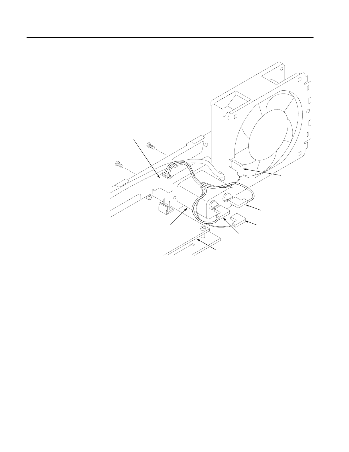
Maintenance
Line power
conductor
Green wire
(ground
conductor)
Blue wire
Line filter
Black wire
Power supply board
Green wire
Figure 6–9: Installing the line filter and line power cable
2. Insert the line filter into the rear chassis and secure it with two screws. The
ground conductor should face the bottom of the instrument. See Figure 6–9.
3. Connect the line power cable to the line filter and the tab on the rear chassis.
See Figure 6–9.
4. Thread the external power cable through the square hole in the rear chassis
and snap the external power jack into place. Insert the key into the slot for
correct alignment.
5. Attach the power supply to the rear chassis with two screws. The fuse side of
the power supply board should face the line filter.
6. If you installed a new power supply, attach the power supply bracket to the
power supply with two screws. The snap post on the bracket should be on
the side of the power supply that is opposite the fuse.
6–18
7. Attach the AC line power cable to the power supply.
TDS3000 Series Service Manual
Page 95

8. Attach the DC power cable to the power supply.
9. Connect the fan power cable to the battery board at J170.
10. Connect the DC power cable to the battery board at J100.
11. Snap the battery board onto the post on the rear chassis.
12. Install two screws to secure the battery board to the rear chassis.
Maintenance
13. Insert the parallel printer connector into the hole in the rear chassis and
3
secure the connector with the two jack posts with the
@16 inch nut driver.
14. Install the power switch extension onto the power switch so that it angles
outward and to the side of the rear chassis assembly.
15. Place the oscilloscope assembly face down on soft surface (such as an
anti-static mat), with the bottom facing you.
16. Position the rear chassis assembly above the oscilloscope assembly.
17. Dress the DC power cable under the power supply and toward you.
18. Thread the external power cable through the top hole in the right side of the
rear chassis and the front chassis, then lower the rear chassis onto the front
chassis. Be sure that the power switch extension goes into the hole in the
front chassis. See Figure 6–7.
19. Snap the left side of the rear chassis onto the two small tabs and then secure
the rear chassis with three screws.
20. Connect the external power cable to the battery board at J200. Make sure
that you route the cable around the front of the battery board; do not route
the cable along side of the battery connector. See Figure 6–7.
TDS3000 Series Service Manual
21. Connect the DC power cable to the main board at J900. Connect the spade
connector from the DC power cable to the front chassis. See Figure 6–7.
22. Connect the parallel printer port cable to the main board. See Figure 6–7.
23. Install the three screws to attach the rear chassis assembly to the front
chassis.
6–19
Page 96

Maintenance
Main Board
You will need a
1
@
inch flat-bladed screwdriver and a Torx T-15 screwdriver to
8
remove the main board.
Removal. Use this procedure to remove the disk drive cable and main board.
1. Place the oscilloscope assembly face down on a soft surface (such as an
anti-static mat), with the bottom facing you.
1
2. Use the
@8 inch flat-bladed screwdriver to carefully lift the disk drive cable
lock on connector J800 on the main board, then pull the flat ribbon cable
from the connector. See Figure 6–10.
Display cable
connector J500
Front - panel
connector J700
Inverter
connector J950
6–20
Screwdriver
Disk drive
connector J800
Figure 6–10: Disk drive and display module cable connectors
TDS3000 Series Service Manual
Page 97

Maintenance
3. Grasp and pull up on the inverter board cable wires to disconnect the cable
from J950 on the main board. See Figure 6–10.
4. Use the
1
@8 inch flat-bladed screwdriver to carefully lift the display cable from
connector J500 on the main board. See Figure 6–10.
5. Grasp and pull up on the front-panel cable wires to disconnect the cable from
J700 on the main board. See Figure 6–10.
6. Use a magnetic Torx T-15 screwdriver (long bit) to remove the four screws
that secure the main board to the front-panel assembly. See Figure 6–11.
Main board
Screws
T-15 (4)
Board snap
TDS3000 Series Service Manual
Release
board snap
Figure 6–11: Main Board
7. Release the two snaps that hold the main board and then lift the main board
out of the front-panel assembly.
6–21
Page 98

Maintenance
Installation. Use this procedure to install the main board and reconnect cables.
1. Place the oscilloscope front-panel assembly face down on soft surface (such
as an anti-static mat), with the bottom facing you.
2. With the front-panel cable dressed out of the way, lower the main board into
the front chassis assembly.
3. Push down on the two main board corners to engage the snaps.
4. Use a magnetic long-bit Torx T-15 screwdriver to install the four screws
that secure the main board to the front-panel assembly. There are two
different screw sizes; use the shorter screw in the hole near the printer port
connector.
5. Insert the display cable into the J500 connector and push down on the
connector to seat it firmly.
NOTE. If after assembling the oscilloscope the display shows streaks, bars,
garbled data, or no image, open the instrument case and make sure that the
display cable is firmly and completely seated into connector J500.
6. Use the 1@8 inch flat-bladed screwdriver to carefully open the disk drive cable
connector J800 on the main board. See Figure 6–10.
7. Insert the disk drive cable (either end) and push down on the connector to
close it.
8. Connect the inverter cable to the main board at J950.
9. Connect the front-panel cable to the main board at J700.
6–22
TDS3000 Series Service Manual
Page 99

Maintenance
Front Chassis and Display
Module
You will need a Torx T-10 screwdriver to remove the front chassis.
Removal. Use this procedure to remove the front chassis and the display module.
1. Place the oscilloscope face down on a soft surface (such as an anti-static
mat), with the bottom facing you.
2. Use the Torx T-10 screwdriver to remove the two screws that secure the
front chassis to the front case. See Figure 6–12.
Front chassis
Screws
T-10 (2)
TDS3000 Series Service Manual
Front panel assembly
Figure 6–12: Front chassis
3. Lift the front chassis out of the front case. Lifting the left end of the chassis
slightly ahead of the right end helps to clear a slight interference at the right
end of the chassis.
6–23
Page 100

Maintenance
NOTE. It is possible to remove the inverter board without removing the front
chassis or display module. If this is the only thing you need to do, skip to step 1
on page 6–26.
4. Place the front chassis with the display facing you. See Figure 6–13.
5. Use your thumbs to slide the top display module tabs up until the overhang-
ing part of the tabs clear the chassis holes. See Figure 6–13.
6. Push the tabs through the chassis holes to remove the display module.
Chassis assembly
Display chassis
6–24
Side up and push out
Figure 6–13: Display module
TDS3000 Series Service Manual
 Loading...