

Page 1

Instructions
TDS 300, TDS 300A, TDS 400 & TDS 400A
Printer Pack
071-0164-00
Page 2

Copyright T ektronix, Inc. 1993. All rights reserved.
T ektronix products are covered by U.S. and foreign patents, issued and pending. Information in this publication supercedes
that in all previously published material. Specifications and price change privileges reserved.
Printed in the U.S.A.
T ektronix, Inc., P.O. Box 1000, Wilsonville, OR 97070–1000
TEKTRONIX and TEK are registered trademarks of T ektronix, Inc.
Page 3

WARRANTY
T ektronix warrants that this product will be free from defects in materials and workmanship for a period of one (1) year
from the date of shipment. If any such product proves defective during this warranty period, T ektronix, at its option, either
will repair the defective product without charge for parts and labor, or will provide a replacement in exchange for the
defective product.
In order to obtain service under this warranty, Customer must notify Tektronix of the defect before the expiration of the
warranty period and make suitable arrangements for the performance of service. Customer shall be responsible for
packaging and shipping the defective product to the service center designated by T ektronix, with shipping charges prepaid.
T ektronix shall pay for the return of the product to Customer if the shipment is to a location within the country in which the
T ektronix service center is located. Customer shall be responsible for paying all shipping charges, duties, taxes, and any
other charges for products returned to any other locations.
This warranty shall not apply to any defect, failure or damage caused by improper use or improper or inadequate
maintenance and care. T ektronix shall not be obligated to furnish service under this warranty a) to repair damage resulting
from attempts by personnel other than T ektronix representatives to install, repair or service the product; b) to repair
damage resulting from improper use or connection to incompatible equipment; or c) to service a product that has been
modified or integrated with other products when the effect of such modification or integration increases the time or
difficulty of servicing the product.
THIS WARRANTY IS GIVEN BY TEKTRONIX WITH RESPECT TO THIS PRODUCT IN LIEU OF ANY
OTHER WARRANTIES, EXPRESSED OR IMPLIED. TEKTRONIX AND ITS VENDORS DISCLAIM ANY
IMPLIED WARRANTIES OF MERCHANTABILITY OR FITNESS FOR A PARTICULAR PURPOSE.
TEKTRONIX’ RESPONSIBILITY TO REPAIR OR REPLACE DEFECTIVE PRODUCTS IS THE SOLE AND
EXCLUSIVE REMEDY PROVIDED TO THE CUST OMER FOR BREACH OF THIS WARRANTY. TEKTRONIX
AND ITS VENDORS WILL NOT BE LIABLE FOR ANY INDIRECT , SPECIAL, INCIDENTAL, OR
CONSEQUENTIAL DAMAGES IRRESPECTIVE OF WHETHER TEKTRONIX OR THE VENDOR HAS
ADVANCE NOTICE OF THE POSSIBILITY OF SUCH DAMAGES.
Page 4

Page 5

Table of Contents
General Safety Summary iii. . . . . . . . . . . . . . . . . . . . . . . . . . . . . . . . . . . .
Preface v. . . . . . . . . . . . . . . . . . . . . . . . . . . . . . . . . . . . . . . . . . . . . . . . . . .
Contacting Tektronix vi. . . . . . . . . . . . . . . . . . . . . . . . . . . . . . . . . . . . . . . . . . . . . .
Getting Started 1. . . . . . . . . . . . . . . . . . . . . . . . . . . . . . . . . . . . . . . . . . . .
Equipment Compatibility 1. . . . . . . . . . . . . . . . . . . . . . . . . . . . . . . . . . . . . . . . . . .
Unpacking the Printer 1. . . . . . . . . . . . . . . . . . . . . . . . . . . . . . . . . . . . . . . . . . . . .
Attaching the Pouch 2. . . . . . . . . . . . . . . . . . . . . . . . . . . . . . . . . . . . . . . . . . . . . . .
Installing the Printer 6. . . . . . . . . . . . . . . . . . . . . . . . . . . . . . . . . . . . . . . . . . . . . . .
Loading Paper 8. . . . . . . . . . . . . . . . . . . . . . . . . . . . . . . . . . . . . . . . . . . . . . . . . . .
Configuring the Oscilloscope 8. . . . . . . . . . . . . . . . . . . . . . . . . . . . . . . . . . . . . . . .
Printing the Hard Copy 8. . . . . . . . . . . . . . . . . . . . . . . . . . . . . . . . . . . . . . . . . . . .
Printer Orientation 8. . . . . . . . . . . . . . . . . . . . . . . . . . . . . . . . . . . . . . . . . . . . . . . .
Ordering Paper 9. . . . . . . . . . . . . . . . . . . . . . . . . . . . . . . . . . . . . . . . . . . . . . . . . . .
Specifications 11. . . . . . . . . . . . . . . . . . . . . . . . . . . . . . . . . . . . . . . . . . . . . .
General Product Description 11. . . . . . . . . . . . . . . . . . . . . . . . . . . . . . . . . . . . . . . .
Nominal Traits 11. . . . . . . . . . . . . . . . . . . . . . . . . . . . . . . . . . . . . . . . . . . . . . . . . . .
W arranted Characteristics 12. . . . . . . . . . . . . . . . . . . . . . . . . . . . . . . . . . . . . . . . . .
T ypical Characteristics 12. . . . . . . . . . . . . . . . . . . . . . . . . . . . . . . . . . . . . . . . . . . . .
Certifications and Compliances 13. . . . . . . . . . . . . . . . . . . . . . . . . . . . . . . . . . . . . .
Maintenance 15. . . . . . . . . . . . . . . . . . . . . . . . . . . . . . . . . . . . . . . . . . . . . . .
Before Servicing 15. . . . . . . . . . . . . . . . . . . . . . . . . . . . . . . . . . . . . . . . . . . . . . . . . .
Troubleshooting 15. . . . . . . . . . . . . . . . . . . . . . . . . . . . . . . . . . . . . . . . . . . . . . . . . .
T ektronix Service 18. . . . . . . . . . . . . . . . . . . . . . . . . . . . . . . . . . . . . . . . . . . . . . . . .
Replaceable Parts List 19. . . . . . . . . . . . . . . . . . . . . . . . . . . . . . . . . . . . . . .
Parts Ordering Information 19. . . . . . . . . . . . . . . . . . . . . . . . . . . . . . . . . . . . . . . . .
Using the Replaceable Parts List 20. . . . . . . . . . . . . . . . . . . . . . . . . . . . . . . . . . . . .
TDS Printer Pack Instructions
i
Page 6

Table of Contents
ii
TDS Printer Pack Instructions
Page 7

General Safety Summary
Review the following safety precautions to avoid injury and prevent damage to
this product or any products connected to it.
Only qualified personnel should perform service procedures.
The Seiko operation manual (included with the printer) provides specific
instructions and precautions for using the printer.
Injury Precautions
Use Proper Power Cord
Avoid Electric Overload
Ground the Product
Do Not Operate Without
Covers
Use Proper Fuse
Do Not Operate in
Wet/Damp Conditions
Do Not Operate in
Explosive Atmosphere
To avoid fire hazard, use only the power cord specified for this product.
To avoid electric shock or fire hazard, do not apply a voltage to a terminal that is
outside the range specified for that terminal.
This product is grounded through the grounding conductor of the power cord. To
avoid electric shock, the grounding conductor must be connected to earth
ground. Before making connections to the input or output terminals of the
product, ensure that the product is properly grounded.
To avoid electric shock or fire hazard, do not operate this product with covers or
panels removed.
To avoid fire hazard, use only the fuse type and rating specified for this product.
To avoid electric shock, do not operate this product in wet or damp conditions.
To avoid injury or fire hazard, do not operate this product in an explosive
atmosphere.
Avoid Exposed Circuitry
TDS Printer Pack Instructions
To avoid injury, remove jewelry such as rings, watches, and other metallic
objects. Do not touch exposed connections and components when power is
present.
iii
Page 8
General Safety Summary
Product Damage Precautions
Use Proper Power Source
Do not operate this product from a power source that applies more than the
voltage specified.
Provide Proper Ventilation
To prevent product overheating, provide proper ventilation.
Safety Terms and Symbols
Terms in This Manual
These terms may appear in this manual:
WARNING. Warning statements identify conditions or practices that could result
in injury or loss of life.
CAUTION. Caution statements identify conditions or practices that could result in
damage to this product or other property.
Terms on the Product
Symbols on the Product
These terms may appear on the product:
DANGER indicates an injury hazard immediately accessible as you read the
marking.
WARNING indicates an injury hazard not immediately accessible as you read the
marking.
CAUTION indicates a hazard to property including the product.
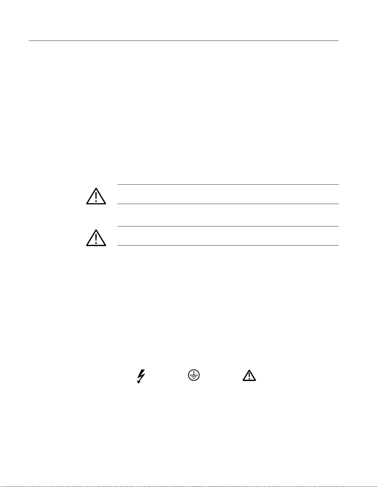
The following symbols may appear on the product:
DANGER
High Voltage
Protective Ground
(Earth) T erminal
ATTENTION
Refer to
Manual
iv
TDS Printer Pack Instructions
Page 9

Preface
This instruction manual provides the installation procedure, specifications, and
service information for the printer pack.
SeikoR provides an Operation Manual with the printer that contains valuable
information and instructions for using the printer.
TDS Printer Pack Instructions
v
Page 10

Preface
Contacting Tektronix
Product
Support
Service
Support
For other
information
To write us Tektronix, Inc.
For application-oriented questions about a Tektronix measurement product, call toll free in North America:
1-800-TEK-WIDE (1-800-835-9433 ext. 2400)
6:00 a.m. – 5:00 p.m. Pacific time
Or contact us by e-mail:
tm_app_supp@tek.com
For product support outside of North America, contact your
local Tektronix distributor or sales office.
Contact your local Tektronix distributor or sales office. Or visit
our web site for a listing of worldwide service locations.
http://www.tek.com
In North America:
1-800-TEK-WIDE (1-800-835-9433)
An operator will direct your call.
P.O. Box 1000
Wilsonville, OR 97070-1000
vi
TDS Printer Pack Instructions
Page 11

Getting Started
The procedures in this section guide you through the process of unpacking and
installing the printer pack on the oscilloscope.
Equipment Compatibility
This product is compatible with the following oscilloscope models:
Option 14 required Option 13 required
TDS 310 B030100 and above TDS 410 All
TDS 320 B030100 and above TDS 420 B020100 and above
TDS 340 All TDS 460 B020100 and above
TDS 350 B030100 and above TDS 410A All
TDS 360 All TDS 420A All
TDS 380 All TDS 430A All
TDS 340A All TDS 460A All
Unpacking the Printer
The shipping carton for the printer option contains the following items:
Quantity Item
1 ea Seiko DPU-414 Printer with manual
1 ea Instructions
1 ea Pouch with mounting plate and Velcro
1 ea Oscilloscope front cover
1 ea 25-pin “D” to 32-pin Centronics cable
1 ea Power cable
5 ea Rolls of thermal paper
Refer to the Replaceable Parts List, page 19, for a complete list of part numbers
and part ordering information.
TDS Printer Pack Instructions
1
Page 12

Getting Started
Attaching the Pouch
Use the following procedure to attach the pouch to the oscilloscope. The
procedure does not require you to use any special tools or equipment or to
remove any cabinet parts.
NOTE. To ensure correct assembly, read and rehearse this entire procedure before
you remove the backing on the Velcro adhesive (step 2).
1. Place the pouch assembly on a flat surface with the bottom of the mounting
plate facing up.
2. Remove the adhesive backing from the Velcro strip. Leave the mating pieces
of the Velcro attached to each other and properly aligned.
CAUTION. To ensure proper positioning of the mounting plate, do not let the
adhesive on the Velcro touch any surface until you properly position and insert
the front edge of the mounting plate.
2
TDS Printer Pack Instructions
Page 13

Getting Started
3. Position the pouch assembly above the cabinet and insert the front edge of
the mounting plate (Figure 1).
Mounting
plate
Insert front edge as shown
Plastic finger under
front panel
Plastic finger under
front panel
Figure 1: Inserting the front edge of the mounting plate
Do not let adhesive touch
the cabinet until the front
edge is inserted.
Mounting plate
Top edge of front panel
TDS Printer Pack Instructions
3
Page 14

Getting Started
4. With the front edge fully inserted, carefully lay the pouch plate down on top
of the cabinet and allow the adhesive to stick (Figure 2). Insert your fingers
between the pouches and press down on the mounting plate along the entire
length of the adhesive — this securely affixes the adhesive.
Press down on area between
pouches to affix the adhesive.
Figure 2: Securing the mounting plate adhesive
5. Lift the pouch plate carefully away from the cabinet making sure the Velcro
strip you just adhered stays in place.
6. Refer to Figure 3. Cover the Velcro on the cabinet with a piece of paper. (The
paper keeps the Velcro on the pouch plate and the cabinet from sticking
together while you position the rear edge of the pouch plate.)
7. Flex the pouch plate upward by grasping the rear of the pouch plate and
pushing toward the front of the oscilloscope.
4
TDS Printer Pack Instructions
Page 15

Getting Started
Mounting
plate
Bow the mounting plate and insert
under the edge of rear panel.
Slots on rear edge of
mounting plate align with
plastic fingers under the
edge of rear panel.
Cover Velcro with
a piece of paper
Velcro
while you position
pouch plate.
Figure 3: Inserting the rear edge of the mounting plate
8. Slip the rear edge of the mounting plate into the gap and allow it to relax
into position.
9. Slide the front and rear ends of the mounting plate from side to side to
ensure that they are properly locked into place.
10. Lift the center of the mounting plate slightly and remove the paper.
11. Press down the mounting plate over the Velcro strip.
CAUTION. Do not use the D-ring foot at the rear of the pouch plate to lift the
oscilloscope. Using the D-ring to lift the oscilloscope may pull the accessory
pouch off the oscilloscope, resulting in damage to the oscilloscope.
TDS Printer Pack Instructions
5
Page 16

Getting Started
Installing the Printer
Install the printer in the rear pouch and connect it to the oscilloscope through two
cables; one cable supplies the power and the other carries printer data.
1. Remove the adhesive backing from the strips of Velcro inside the rear pouch.
Carefully position the printer over the Velcro and firmly press the printer into
place.
Figure 4: Printer and cable orientation
6
TDS Printer Pack Instructions
Page 17

Getting Started
2. Carefully lift the printer out of the pouch making sure the Velcro strips stay
attached to the printer.
3. Locate the power jack on the rear of the printer, position it near the cutout on
the pouch, and plug in the right-angle end of the power cable.
4. Connect the data cable to the Centronics compatable connector on the rear of
the printer. Secure the cable with the clips on the connector.
5. Place the printer in the rear compartment of the pouch and seat the Velcro.
6. Route the power and data cables through the opening in the rear of the
printer pouch. See Figure 5.
TDS Printer Pack Instructions
Figure 5: Connecting the cables from the printer to the oscilloscope
7. Route the data cable so that it lies close to the cabinet to avoid interfering
with the power cord that coils around the feet on the rear panel.
8. Connect and secure the 25-pin “D” connector of the data cable to the parallel
printer connector on the oscilloscope.
9. Connect the power cable to the printer power jack on the oscilloscope.
7
Page 18

Getting Started
Loading Paper
Refer to the instructions in the Seiko manual for loading paper into the printer.
1. Turn on the oscilloscope.
2. Load paper into the printer according to instructions detailed in the Seiko
manual.
3. Run the printer diagnostics. (Refer to the Seiko manual.)
Configuring the Oscilloscope
Set the hardcopy parameters of the oscilloscope before attempting to print a hard
copy.
TDS 400 Series
Configuration
TDS 300 Series
Configuration
Printing the Hard Copy
Printer Orientation
1. Press SHIFT HARDCOPY MENU
2. Press –more– until the DPU 411 selection shows.
3. Press DPU 411.
4. Press Port
1. Press UTILITY
2. Press Hcp Format.
3. Press –more– until the DPU 411/II selection shows.
4. Press DPU 411/II.
Press HARDCOPY to start the printer. Refer to the oscilloscope user or
instruction manual for more information on how to use the hardcopy command.
➞ Centronics.
➞ System I/O ➞ Hcp Port ➞ Centronics.
➞ Format.
Although Seiko recommends installing the printer on a flat, stable surface, the
Printer Pack allows you to use the printer with the oscilloscope inclined at any
angle up to 90_ from horizontal.
8
TDS Printer Pack Instructions
Page 19

Ordering Paper
Getting Started
You can obtain thermal paper for the printer in one of three ways:
1. Refer to the Replaceable Parts List, page 19, for the part number of the
thermal paper and part ordering information.
2. Contact one of the Seiko offices listed on the back of the Seiko manual
included with the printer.
3. Call the telephone number printed on the box of paper included with the
printer pack.
TDS Printer Pack Instructions
9
Page 20

Getting Started
10
TDS Printer Pack Instructions
Page 21

Specifications
This section provides specifications for the digitizing oscilloscope with the
printer pack installed. It begins with a general description of the printer pack
option. Three subsections follow, one for each of three classes of traits: nominal
traits, warranted characteristics, and typical characteristics.
General Product Description
The printer pack provides the digitizing oscilloscope with integrated thermal
printer capability. Here are some key features of the printer pack:
H Durable pouch, mounted conveniently on top of the oscilloscope, provides
protection for the printer and supplies additional storage for spare paper,
probes, and other accessories.
H Printer power supplied by the RS-232/Centronics adapter allows you to
move and operate the printer as part of the oscilloscope.
H Lightweight and durable printer uses four-inch thermal paper for high-con-
trast hard copies.
Nominal Traits
H A 128 K-word printer spooler allows you to use the oscilloscope while a
hard copy is printing (TDS 400 and TDS 400A Series only).
Nominal trait descriptions are simple statements of fact. For example, “640 ×
480” is a description for the trait “Pixel resolution” rather than the limit of a
performance requirement.
Name Description
Print head, method Thermal serial dot
Interface Centronics
Controls On/Off, On line, and Feed
Pixel resolution 640 × 480
TDS Printer Pack Instructions
11
Page 22

Specifications
Warranted Characteristics
The description for each warranted characteristic is a quantifiable performance
requirement. This subsection lists only warranted characteristics.
NOTE. Installing the printer pack option on a digitizing oscilloscope reduces the
warranted characteristics for that product to the specifications listed below.
Name Description
Temperature range 0_ C to 40_ C, operating; –20_ C to +60_ C, non-operating
Relative humidity 30% to 80% relative humidity, operating;
Typical Characteristics
40_ C at 95% relative humidity , non-operating
The description for each typical characteristic makes a statement in terms of
typical or average performance. The warranty does not apply to typical characteristics.
Name Description
Weight 11.3 kg (25 lbs), TDS 400 series oscilloscope and option;
9.5 kg (21 lbs), TDS 300 series oscilloscope and option;
4.5 kg (10 lbs), option packaged for shipping
Overall dimensions
(H × W × D)
Printer power consumption ≤ 14 Watts
Print time Approximately three minutes (landscape)
Printing width 89.6 mm (3.53 in)
Printing height:
landscape Approximately 75 mm (2.95 in)
portrait Approximately 100 mm (3.94 in)
Service life 13,000 copies
241 mm × 362 mm × 471 mm
(9.5 in × 14.25 in × 18.55 in)
12
TDS Printer Pack Instructions
Page 23

Certifications and Compliances
The product complies with the following certifications:
Name Description
Specifications
EC Declaration of Conformity –
EMC
FCC Compliance Emissions comply with FCC Code of Federal Regulations 47, Part 15, Subpart B, Class A Limits
Meets intent of Directive 89/336/EEC for Electromagnetic Compatibility. Compliance was
demonstrated to the following specifications as listed in the Official Journal of the European
Communities:
EN 50081-1 Emissions:
EN 55022 Class B Radiated and Conducted Emissions
EN 50082-1 Immunity:
IEC 801-2 Electrostatic Discharge Immunity
IEC 801-3 RF Electromagnetic Field Immunity
IEC 801-4 Electrical Fast Transient/Burst Immunity
IEC 801-5 Power Line Surge Immunity
TDS Printer Pack Instructions
13
Page 24

Specifications
14
TDS Printer Pack Instructions
Page 25

Maintenance
Before Servicing
This section provides you with information you need to know if you encounter a
problem with the printer. Before Servicing lists sources of other safety and
service information that are important to consider. The diagram in Troubleshoot-
ing helps you isolate the particular module at fault. The subsection Tektronix
Service tells you what to do if the printer or other warranted parts are at fault.
Refer to the Replaceable Parts List on page 19 for specific part numbers and part
descriptions.
Only qualified service personnel should attempt to repair the printer or the
oscilloscope. Before you attempt to service the printer or the oscilloscope please
read the following information:
H The Seiko Operation Manual supplied with the printer.
H The General Safety Summary on page iii.
Troubleshooting
A failure of the printer may be caused by one or more of the following faults:
H Improper installation or setup of the printer
H Faulty connections between the printer and the oscilloscope
H A malfunction of the interface module
H A failure of the printer itself
Refer to the troubleshooting tree in Figures 6 and 7 to help isolate the cause of a
printer malfunction.
TDS Printer Pack Instructions
15
Page 26

Maintenance
Printer does not work.
Path for
TDS 300
TDS 400A
Are the
power and on-line
LEDs lit?
paper properly
loaded?
Perform printer self-test.
Does the
Yes
self-test print
out?
No
Yes
Is
Yes
No
No
Check for > +6 VDC on
power cable.
Voltage present?
Yes
Replace printer.
Load paper.
Replace printer.
No
Replace interface module
16
Path for
TDS 400
Verify HARDCOPY parameters
and I/O port are configured
Yes
Does TDS
have firmware
V2.XX?
Yes
properly.
Go to
1
No
Contact Service Center.
Figure 6: Troubleshooting tree — part 1
TDS Printer Pack Instructions
Page 27

1
Attempt hardcopy.
Maintenance
Obtain printout?
No
Replace or substitute
data cable.
Attempt hardcopy.
Obtain printout?
Yes
Done.
Yes
No
Done.
Replace
interface module.
Attempt hardcopy.
Obtain printout?
No
oscilloscope or contact the
T ektronix Service Center.
Troubleshoot
TDS Printer Pack Instructions
Yes
Done.
Figure 7: Troubleshooting tree — part 2
17
Page 28

Maintenance
Tektronix Service
Tektronix provides service to cover repair or replacement under warranty as well
as other services that may provide a cost-effective answer to your service needs.
Warranty Service
For More Information
Tektronix warrants the printer pack for one year from date of purchase. (The
warranty appears at the front of this manual.)
Contact your local Tektronix service center or sales engineer for more information on the warranty service just described.
18
TDS Printer Pack Instructions
Page 29

Replaceable Parts List
This section contains a list of the replaceable modules for the printer pack. Use
this list to identify and order replacement parts.
Parts Ordering Information
Replacement parts are available through your local Tektronix field office or
representative.
Changes to Tektronix products are sometimes made to accommodate improved
components as they become available and to give you the benefit of the latest
improvements. Therefore, when ordering parts, it is important to include the
following information in your order:
H Part number
H Instrument type or model number
H Instrument serial number
H Instrument modification number, if applicable
Module Servicing
If you order a part that has been replaced with a different or improved part, your
local Tektronix field office or representative will contact you concerning any
change in part number.
Change information, if any, is located at the rear of this manual.
Modules can be serviced by selecting one of the following three options. Contact
your local Tektronix service center or representative for repair assistance.
Module Exchange. In some cases you may exchange your module for a remanufactured module. These modules cost significantly less than new modules and
meet the same factory specifications. For more information about the module
exchange program, call 1-800-TEK-WIDE, extension 6630.
Module Repair and Return. You may ship your module to us for repair, after which
we will return it to you.
New Modules. You may purchase replacement modules in the same way as other
replacement parts.
TDS Printer Pack Instructions
19
Page 30

Replaceable Parts List
Using the Replaceable Parts List
This section contains a list of the mechanical and/or electrical components that
are replaceable for the printer pack. Use this list to identify and order replacement parts. The following table describes each column in the parts list.
Parts List Column Descriptions
Column Column name Description
1 Figure & Index Number Items in this section are referenced by figure and index numbers to the exploded view
illustrations that follow.
2 Tektronix Part Number Use this part number when ordering replacement parts from Tektronix.
3 and 4 Serial Number Column three indicates the serial number at which the part was first effective. Column four
indicates the serial number at which the part was discontinued. No entries indicates the part is
good for all serial numbers.
5 Qty This indicates the quantity of parts used.
6 Name & Description An item name is separated from the description by a colon (:). Because of space limitations, an
item name may sometimes appear as incomplete. Use the U.S. Federal Catalog handbook
H6-1 for further item name identification.
7 Mfr. Code This indicates the code of the actual manufacturer of the part.
8 Mfr. Part Number This indicates the actual manufacturer’s or vendor’s part number.
Abbreviations
Mfr. Code to Manufacturer
Cross Index
Abbreviations conform to American National Standard ANSI Y1.1–1972.
The table titled Manufacturers Cross Index shows codes, names, and addresses
of manufacturers or vendors of components listed in the parts list.
20
TDS Printer Pack Instructions
Page 31

Replaceable Parts List
Manufacturers Cross Index
Mfr.
code
62712 SEIKO INSTRUMENTS USA 2990 W LOMITA BLVD T ORRANCE CA 90505–5102
80009 TEKTRONIX INC 14150 SW KARL BRAUN DR
Manufacturer Address City , state, zip code
BEAVERT ON OR 97077–0001
PO BOX 500
Replaceable Parts List
Fig. &
index
number
Tektronix part
number
006–7580–00 5 THERMAL PAPER:112MM X 48MM X 28M 62712 TP411–451–25C
016–1230–02 1 POUCH:POUCH & PLATE 80009 016123002
071–0164–00 1 MANUAL,TECH:INSTRUCTION, PRINTER PACK 80009 071016400
119–5835–00 1 PRINTER,THERMAL:SERIAL,DOT,RS–232 80009 119583500
174–3476–00 1 CABLE ASSY,SP:CENT–DB25,10 L 80009 174347600
174–3030–00 1 CABLE ASSY,PWR:DISCRETE,POWER 80009 174303000
200–3232–01 1 INSTRUMENT FRONT COVER 80009 200323201
Serial no.
effective
Serial no.
discont’d
Qty Name & description
Mfr.
code
Mfr. part number
TDS Printer Pack Instructions
21
Page 32

Replaceable Parts List
22
TDS Printer Pack Instructions
Page 33

Page 34

 Loading...