

Page 1

Instructions
TDS 200-Series
Extension Modules
071-0409-01
*P071040901*
071040901
Page 2

Page 3

Instructions
TDS 200-Series Extension Modules
071-0409-01
This manual supports TDS2CM firmware version
1.04 and above, and TDS2MM firmware version
1.00 and above when used with TDS 210 and
TDS 220 firmware version 1.06 and above, or
TDS 224 firmware all versions. Refer to Read Me
First on page 1 for more information.
Page 4

Copyright © T ektronix, Inc. All rights reserved. T ektronix products are covered by U.S. and foreign patents, issued and
pending. Information in this publication supercedes that in all previously
published material. Specifications and price change privileges reserved.
T ektronix, Inc., P.O. Box 1000, Wilsonville, OR 97070–1000
TEKTRONIX and TEK are registered trademarks of T ektronix, Inc.
Page 5

WARRANTY SUMMARY
(TDS2CM and TDS2MM Extension Modules)
Tektronix warrants that the products that it manufactures and sells will be free from defects
in materials and workmanship for a period of three (3) years from the date of shipment
from an authorized Tektronix distributor. If a product proves defective within the
respective period, Tektronix will provide repair or replacement as described in the
complete warranty statement.
To arrange for service or obtain a copy of the complete warranty statement, please contact
your nearest Tektronix sales and service office.
EXCEPT AS PROVIDED IN THIS SUMMARY OR THE APPLICABLE WARRANTY
STATEMENT, TEKTRONIX MAKES NO WARRANTY OF ANY KIND, EXPRESS
OR IMPLIED, INCLUDING WITHOUT LIMITATION THE IMPLIED WARRANTIES
OF MERCHANTABILITY AND FITNESS FOR A PARTICULAR PURPOSE. IN NO
EVENT SHALL TEKTRONIX BE LIABLE FOR INDIRECT, SPECIAL OR
CONSEQUENTIAL DAMAGES.
Page 6

Page 7

Table of Contents
General Safety Summary ii. . . . . . . . . . . . . . . . . . . . . . . . . . . .
Preface iv. . . . . . . . . . . . . . . . . . . . . . . . . . . . . . . . . . . . . . . . . . . .
Conventions iv. . . . . . . . . . . . . . . . . . . . . . . . . . . . . . . . . . . . . . . .
Command Entry v. . . . . . . . . . . . . . . . . . . . . . . . . . . . . . . . . . . . .
Contacting T ektronix vi. . . . . . . . . . . . . . . . . . . . . . . . . . . . . . . . .
Getting Started 1. . . . . . . . . . . . . . . . . . . . . . . . . . . . . . . . . . . . .
Read Me First 1. . . . . . . . . . . . . . . . . . . . . . . . . . . . . . . . . . . . . .
Features 2. . . . . . . . . . . . . . . . . . . . . . . . . . . . . . . . . . . . . . . . . . .
Removing and Installing Modules 3. . . . . . . . . . . . . . . . . . . . . . .
Checking Module Installation 6. . . . . . . . . . . . . . . . . . . . . . . . . .
Troubleshooting Module Installation 6. . . . . . . . . . . . . . . . . . . . .
Making a Hard Copy 7. . . . . . . . . . . . . . . . . . . . . . . . . . . . . . . . .
TDS2CM Communications Module 10. . . . . . . . . . . . . . . . . . . .
RS-232 Setup 11. . . . . . . . . . . . . . . . . . . . . . . . . . . . . . . . . . . . . . .
GPIB Setup 21. . . . . . . . . . . . . . . . . . . . . . . . . . . . . . . . . . . . . . . .
TDS2MM Measurement Module 27. . . . . . . . . . . . . . . . . . . . . .
Changed Operations for TDS 210 and TDS 220 with Firmware
Below V 2.00 28. . . . . . . . . . . . . . . . . . . . . . . . . . . . . . . . . . . .
Signal Measurements 29. . . . . . . . . . . . . . . . . . . . . . . . . . . . . . . . .
Using the FFT 30. . . . . . . . . . . . . . . . . . . . . . . . . . . . . . . . . . . . . .
Appendix A: Certifications and Compliances 43. . . . . . . . . . . .
Appendix B: Comparing GPIB and RS-232 44. . . . . . . . . . . . .
Appendix C: Manuals 46. . . . . . . . . . . . . . . . . . . . . . . . . . . . . . .
TDS 200-Series Extension Module Instructions
i
Page 8

General Safety Summary
Review the following safety precautions to avoid injury and prevent
damage to this product or any products connected to it. T o avoid
potential hazards, use the product only as specified.
Only qualified personnel should perform service procedures.
While using this product, you may need to access other parts of the
system. Read the General Safety Summary in other system manuals
for warnings and cautions related to operating the system.
Injury Precautions
Avoid Electric Overload. To avoid electric shock or fire hazard, do not
apply a voltage to a terminal that is outside the range specified for
that terminal.
Do Not Operate Without Covers. To avoid electric shock or fire hazard,
do not operate this product with covers or panels removed.
Do Not Operate in Wet/Damp Conditions. To avoid electric shock, do not
operate this product in wet or damp conditions.
Do Not Operate in an Explosive Atmosphere. T o avoid injury or fire
hazard, do not operate this product in an explosive atmosphere.
ii
TDS 200-Series Extension Module Instructions
Page 9
General Safety Summary
Product Damage Precautions
Do Not Operate With Suspected Failures. If you suspect there is damage
to this product, have it inspected by qualified service personnel.
Safety Terms and Symbols
Terms in This Manual. These terms may appear in this manual:
CAUTION. Caution statements identify conditions or practices that
could result in damage to this product or other property.
Terms on the Product. These terms may appear on the product:
DANGER indicates an injury hazard immediately accessible as you
read the marking.
WARNING indicates an injury hazard not immediately accessible as
you read the marking.
CAUTION indicates a hazard to property including the product.
Symbols on the Product. These symbols may appear on the product:
DANGER
High Voltage
Protective Ground
(Earth) T erminal
TDS 200-Series Extension Module Instructions
ATTENTION
Refer to Manual
Double
Insulated
iii
Page 10

Preface
These instructions describe how to install, set up, and test the
TDS2CM and TDS2MM Extension modules. This manual presumes
that you understand how to operate the TDS 200-Series oscilloscope.
Conventions
This manual uses the following conventions:
H Labeled oscilloscope panel buttons are shown in the manual in all
uppercase letters. For example: UTILITY, HARDCOPY.
H On-screen menu items are shown in the manual with the first
letter of each menu word in upper case. For example: Options,
Recall Factory.
H A list of panel buttons, separated by the " symbol, represents the
order in which to push the listed buttons. For example,
UTILITY
UTILITY panel button, then push the side menu button to the
right of the Options menu item, and then push the side menu
button to the right of the RS-232 menu item.
" Options " RS-232 means that you first push the
iv
TDS 200-Series Extension Module Instructions
Page 11

Command Entry
Follow these general rules when entering oscilloscope commands
over the RS-232 or GPIB bus:
You can enter commands in upper or lower case.
You can abbreviate many oscilloscope commands. These
abbreviations are shown in uppercase letters. For example, the
command ACQuire:NUMAVg can be entered simply as
ACQ:NUMAV or acq:numav.
You can precede any command with white space characters.
White space characters include any combination of the ASCII
control characters 00 through 09 and 0B through 20 hexadecimal
(0 through 9 and 11 through 32 decimal).
The oscilloscope ignores commands that consist of just a
combination of white space characters and line feeds.
Refer to the TDS 200-Series Digital Real-Time Oscilloscope
Programmer Manual (071-0493-XX) for more information.
Preface
TDS 200-Series Extension Module Instructions
v
Page 12

Preface
Contacting Tektronix
Product
support
Service
support
For other
information
To write us Tektronix, Inc.
Web site www .Tektronix.com
For questions about using T ektronix measurement
products, call toll free in North America:
1-800-TEK-WIDE (1-800-835-9433 ext. 2400)
6:00 a.m. – 5:00 p.m. Pacific time
Or contact us by e-mail:
tm_app_supp@tek.com
For product support outside of North America,
contact your local T ektronix distributor or sales
office.
T ektronix offers extended warranty and calibration
programs as options on many products. Contact your
local T ektronix distributor or sales office.
For a listing of worldwide service centers, visit our
web site.
In North America:
1-800-TEK-WIDE (1-800-835-9433)
An operator will direct your call.
P.O. Box 1000
Wilsonville, OR 97070-1000
USA
vi
TDS 200-Series Extension Module Instructions
Page 13

Getting Started
This chapter describes important module and oscilloscope dependencies, and how to install and check the TDS 200-Series extension
modules.
Read Me First
NOTE. Read the following text before installing your module. To
display oscilloscope and module firmware version numbers, press
UTILITY System Status Misc.
TDS2MM and TDS 200-Series
The TDS2MM Module operates with TDS 210 and TDS 220 with
firmware version 1.06 and above, and with TDS 224 firmware all
versions. Contact Tektronix for information on how to upgrade your
TDS 200-Series oscilloscope firmware.
Seiko Printer Support
Seiko printer support (DPU411, DPU412) is only available with the
following firmware configurations:
Module and firmware TDS 210/220 firmware TDS 224 firmware
TDS2CM v1.04 and above1v1.09 and above All
TDS2MM v1.00 and above v1.06 and above All
1
You cannot select the DPU411 or DPU412 over a remote interface with
TDS2CM v1.03 and below.
TDS 200-Series Extension Module Instructions
1
Page 14

Getting Started
Features
The following table lists the module features.
Module Centronics RS-232 GPIB
TDS2CM
TDS2MM
FFT, rise/fall
time, pos/neg
pulse width
2
TDS 200-Series Extension Module Instructions
Page 15

Removing and Installing Modules
The following sections describe how to safely remove and install a
module on your oscilloscope.
Preventing Electrostatic Damage
CAUTION. Electrostatic discharge (ESD) can damage components in
the extension module and the oscilloscope. To prevent ESD, follow
the steps below when installing, removing, or handling the extension
modules:
1. Always turn off the oscilloscope before removing or installing
extension modules.
2. Handle extension modules as little as possible.
3. Transport and store extension modules in a static-protected bag
or container.
4. Do not slide the extension module over any surface
5. Wear a grounded antistatic wrist strap to discharge the static
voltage from your body while installing or removing an extension
module from the oscilloscope.
Getting Started
6. Do not touch the oscilloscope extension module connector pins.
7. Do not use any devices capable of generating or holding a static
charge in the work area where you install or remove extension
modules.
8. Avoid handling modules in areas that have a floor or work-sur-
face covering capable of generating a static charge.
9. Make sure that you install the extension module cover after you
remove an extension module.
TDS 200-Series Extension Module Instructions
3
Page 16
Getting Started
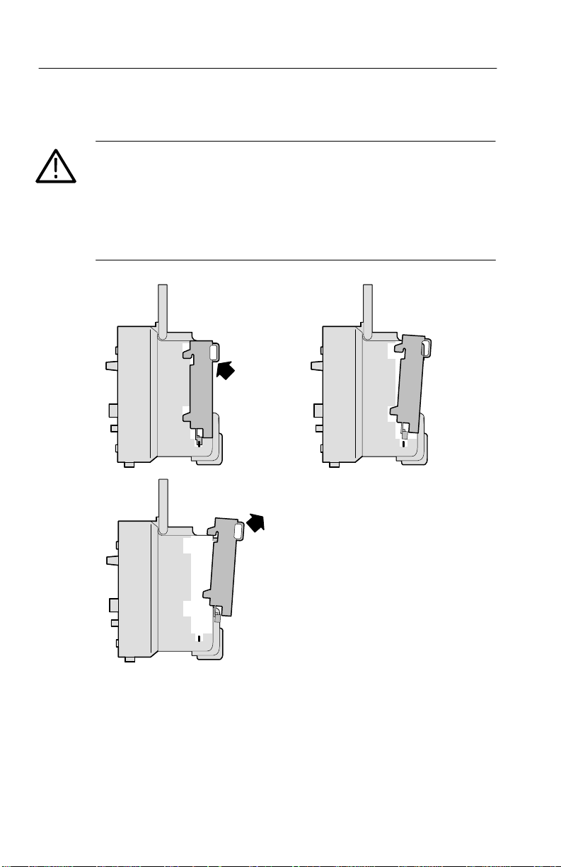
Removing an Extension Module
CAUTION. Electrostatic discharge (ESD) can damage components in
the extension module and the oscilloscope. To prevent ESD, follow
the steps on page 3 when installing, removing, or handling the
extension modules.
After removing a module, install the dummy module cover to protect
the contact pins.
1 2
3
4
TDS 200-Series Extension Module Instructions
Page 17

Getting Started
Installing an Extension Module
Make sure that you align the module connector to the oscilloscope
connector pins before seating the module.
1
3 4
5
2
TDS 200-Series Extension Module Instructions
5
Page 18

Getting Started
Checking Module Installation
T o check that the extension module is correctly installed, turn on the
oscilloscope. The power-up screen should include the message
”Extension Module Passed”. If the oscilloscope does not recognize
the extension module at power-up, do the steps in Troubleshooting
Module Installation below.
Troubleshooting Module Installation
If the oscilloscope does not recognize the extension module at
power-up, do the following steps:
1. Turn off the oscilloscope.
2. Follow the ESD precautions listed on page 3.
3. Disconnect all cables from the extension module.
4. Remove the extension module (refer to page 4).
5. Examine the oscilloscope option connector for bent, broken, or
missing pins. If any pins are bent, carefully straighten them out.
6. Reinstall the extension module onto the oscilloscope.
7. Turn on the oscilloscope. If the oscilloscope still does not show
the module installed, contact the nearest T ektronix service center.
6
TDS 200-Series Extension Module Instructions
Page 19

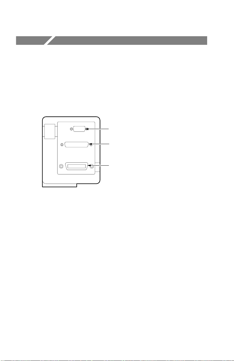
Making a Hard Copy
The extension modules have a hard copy feature that lets you print
the oscilloscope screen data on a printer.
Getting Started
RS-232 connector
Centronics connector
GPIB connector
TDS 200-Series Extension Module Instructions
7
Page 20

Getting Started
Hard Copy Setup
T o setup the extension module, do the following:
1. Turn on the oscilloscope.
2. Push UTILITY Options Hard Copy Setup.
3. Push the menu button next to the menu item to change the
Menu Settings Comments
Layout Portrait, Landscape Hard copy output orientation
Format Epson, ThinkJet, DeskJet,
Port Centronics, RS-232, GPIB Module port to which the
Abort
Hardcopy
1
settings to match those of your printer device. The following
table lists the settings you can change.
The oscilloscope stores these settings until you change them.
Turning off the oscilloscope does not erase these settings.
Type of device connected to
LaserJet, BMP, PCX,
EPSIMAGE, INTERLEAF,
1
DPU411
Refer to Read Me First on page 1 for more Seiko printer information.
, DPU412
1
the hard copy port
printer is connected
Stops sending screen data to
the hard copy device
NOTE. If you use the RS-232 or GPIB port, you also need to set up
the parameters for the port appropriately for your printer.
8
TDS 200-Series Extension Module Instructions
Page 21

Getting Started
Testing the Hard Copy Port
1. If you have already connected the oscilloscope to a printer, go to
step 4.
2. Turn off the oscilloscope and the printer.
3. Connect the oscilloscope to the printer using the appropriate
cable.
4. Turn on the oscilloscope and the printer.
5. If you have not done so already, do the hard copy setup
appropriate for your extension module. Refer to page 8.
6. On the oscilloscope, push the HARDCOPY button. The printer
should begin printing a copy of the oscilloscope screen after a
few seconds.
Printing an Oscilloscope Screen
T o print the screen data, push the HARDCOPY button. The
oscilloscope takes a few seconds to capture the screen data and send
it to the printer. The printer then begins printing a copy of the
oscilloscope screen. Your printer settings determine how long it
takes to print the screen data.
TDS 200-Series Extension Module Instructions
9
Page 22
TDS2CM Communications Module
This chapter describes how to set up and test the TDS2CM
Communications Extension Module RS-232 and GPIB interfaces.
The TDS2CM Module information also applies to the communications portion of the TDS2MM Measurement Module.
RS-232 connector
Centronics connector
GPIB connector
10
TDS 200-Series Extension Module Instructions
Page 23

RS-232 Setup
This section describes how to set up and test the extension module
RS-232 interface. RS-232 is an 8-bit serial communications standard
that lets the oscilloscope communicate with an external RS-232
device such as a computer, terminal, or printer. The standard defines
two device types: Data T erminal Equipment (DTE) and Data
Communications Equipment (DCE). The TDS 200-Series
oscilloscope is a DTE device.
RS-232 Conventions on page 19 describes RS-232 conventions.
RS-232 Connector Pinout Diagram on page 20 shows a diagram of
the 9-pin RS-232 connector with its pin numbers and signal
assignments.
TDS2CM Communications Module
TDS 200-Series Extension Module Instructions
11
Page 24

TDS2CM Communications Module
Selecting an RS-232 Cable
You will need an RS-232 cable to connect the oscilloscope to an
external device. Use the following table to choose the correct cable
to connect the module to your RS-232 equipment.
To connect the
oscilloscope to
PC/AT or laptop
computers
PCs with 25-pin serial
port connector
Serial printers, such as
an HP Deskjet, and Sun
workstations
Telephone modems 9-pin female to 25-pin male,
You need this type cable
9-pin female to 9-pin female, null
modem
9-pin female to 25-pin female, null
modem
9-pin female to 25-pin male,
null modem
modem
Tektronix part
number
012-1379-00
012-1380-00
012-1298-00
012-1241-00
12
TDS 200-Series Extension Module Instructions
Page 25

TDS2CM Communications Module
Connecting an External Device
Follow these guidelines when connecting the module to an external
RS-232 device:
Use the correct cable (refer to the table on page 12).
Use a cable that is no longer than 50 feet.
Turn off the oscilloscope and the external device before inserting
the cable into the connectors.
Connect the oscilloscope only to a DCE device.
Check that the oscilloscope signal ground (pin 5) is connected to
the external device signal ground.
Connect the chassis ground of the oscilloscope to the chassis
ground of the external device.
TDS 200-Series Extension Module Instructions
13
Page 26

TDS2CM Communications Module
RS-232 Settings
T o set the oscilloscope RS-232 interface:
1. Push UTILITY
Options RS-232.
2. Push the menu button next to the menu item to change settings to
match those of the external device. The following table lists the
settings you can change.
The oscilloscope stores these settings until you change them.
Turning off the oscilloscope does not erase these settings.
Menu Settings Comments
Set to
defaults
Baud 300, 600, 1200,
2400, 4800, 9600,
19200
Flow Control Hardflag, Softflag,
None
EOL String CR, LF, CR/LF,
LF/CR
Parity None, Even, Odd Adds an error check bit (ninth bit) to
Sets the RS-232 interface to factory
defaults (Baud=9600, Flow=Hardflag,
EOL String=LF, Parity=None).
Sets the data transmission rate.
Sets data flow control (Softflag=Xon/
Xoff, Hardflag= RTS/CTS).
Use hardware flagging when transferring binary data.
Sets the end-of-line terminator sent by
the oscilloscope.
each character.
14
TDS 200-Series Extension Module Instructions
Page 27

TDS2CM Communications Module
Testing the RS-232 Interface
T o test the oscilloscope RS-232 interface:
1. Connect the oscilloscope to a personal computer (PC) using an
appropriate RS-232 cable (refer to the table on page 12).
2. Turn on the PC.
3. On the PC, run a terminal-emulator program such as Microsoft
Windows Terminal. Make sure the PC serial port is set as
follows:
Function Setting
Baud rate
Data flow control Hardflag
Parity None
EOL string LF
9600
4. Turn on the oscilloscope.
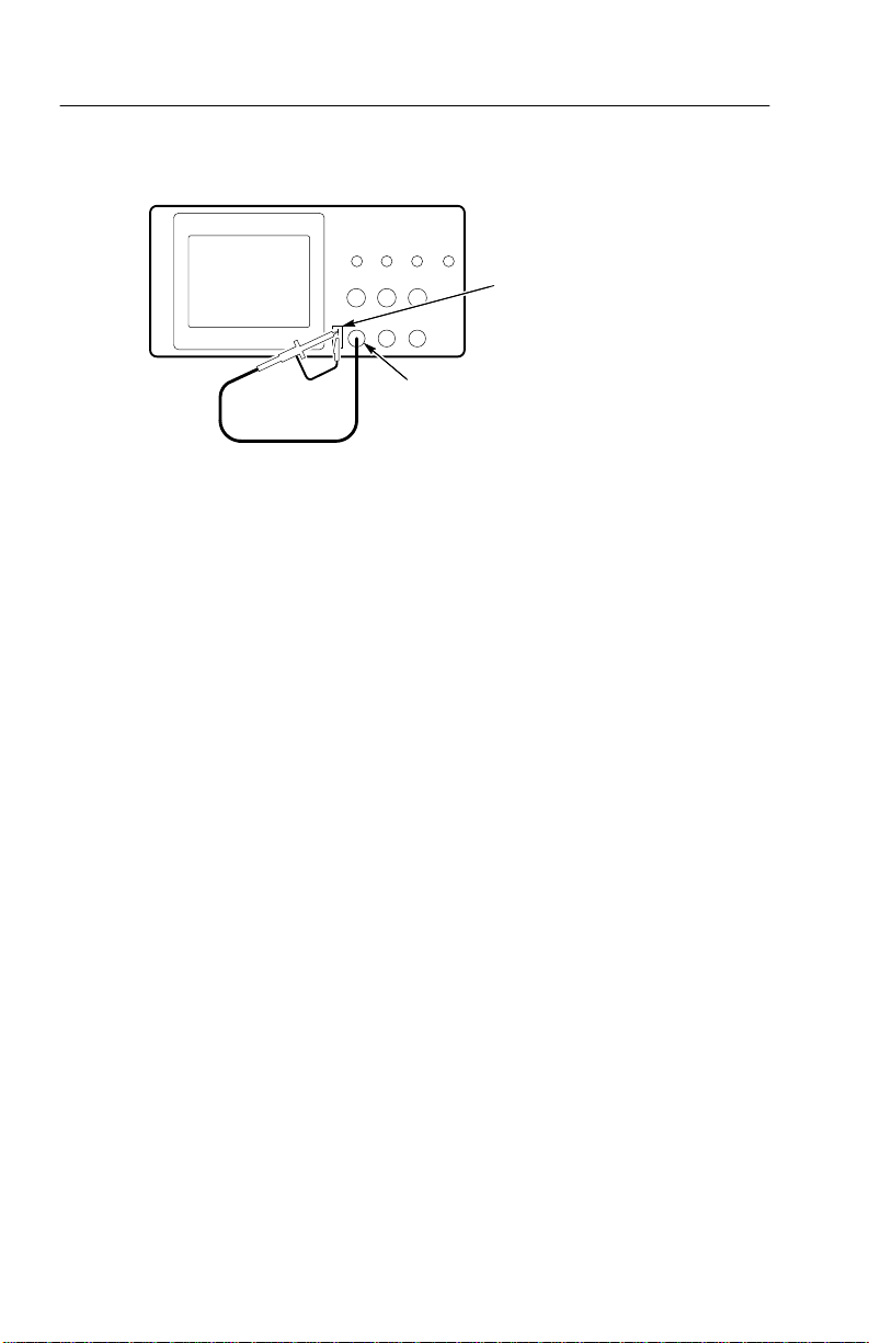
5. Connect the oscilloscope probe to the channel 1 input connector.
Attach the probe tip and ground lead to the PROBE COMP
connectors.
The PROBE COMP signal is a square wave with a frequency
of ≈1 kHz and a peak voltage of ≈5 V. The following figure
shows how to hook up the probe to the oscilloscope.
TDS 200-Series Extension Module Instructions
15
Page 28
TDS2CM Communications Module
TDS 200 Series Digitizing oscilloscope
6. On the oscilloscope, push UTILITY Options RS-232.
7. Check that the menu settings match those listed in the table on
page 15.
8. From your PC terminal program, type ID?, then press the
RETURN key to send the command. The oscilloscope sends back
its identification string, which should look similar to the
following:
PROBE COMP
CH 1 connector
16
If you do not get any response, refer to the troubleshooting steps
that start on page 18.
9. Send the command FACtory to reset the oscilloscope to factory
settings.
10.Send the command AUTOSet EXECute to have the oscilloscope
automatically acquire the input signal.
TDS 200-Series Extension Module Instructions
Page 29

TDS2CM Communications Module
11. Send the command MEASUrement:IMMed:SOURCE CH1 to
select measurements on channel 1.
12.Send the command MEASUrement:IMMed:TYPe PK2 to set up
the voltage measurement.
13.Send the query MEASUrement:IMMed:VALue? to request the
measurement result. The oscilloscope will respond with a result
similar to , which is the voltage measurement of the
PROBE COMP signal using the standard 10x probe.
This completes the RS-232 interface test.
TDS 200-Series Extension Module Instructions
17
Page 30

TDS2CM Communications Module
RS-232 Troubleshooting
If the oscilloscope and the external device (personal computer or
printer) have trouble communicating, use the following steps to
correct the problem:
1. Verify that the module is working. Refer to Checking Module
Installation on page 6.
2. Check that you are using the correct RS-232 cable. Determine
whether your external device requires a null-modem or a
straight-through connection. Refer to the table on page 12 for
information about RS-232 cables.
3. Check that the RS-232 cable is firmly connected to both the
oscilloscope and the correct port on the external device.
4. Check that the printer or the program on the personal computer is
using the same port to which you connected the RS-232 cable.
Try your program or printer again.
5. Check that the oscilloscope RS-232 settings match the settings
used by the external device:
a. Determine the RS-232 settings for the external device.
18
b. On the oscilloscope, push UTILITY
Options RS-232.
c. Set the oscilloscope to match the settings of the external
device.
d. Try your terminal-emulator program or printer again.
6. Try setting both the oscilloscope and the external device to a
slower baud rate.
TDS 200-Series Extension Module Instructions
Page 31

TDS2CM Communications Module
RS-232 Conventions
There are processing conventions that are specific to the RS-232
interface. The next sections discuss transferring binary data,
processing break signals, reporting RS-232 I/O errors, and checking
command status.
Transferring Binary Data
When using the RS-232 port to transfer binary data to the
oscilloscope, note the following points:
Use hardware flagging (RTS/CTS) whenever possible. Hardware
flagging guarantees no data loss.
All eight bits of binary data contain meaningful information. T o
make sure that all eight bits are received or transmitted,
configure the external RS-232 device to receive and transmit
eight-bit characters (set the RS-232 word length to eight bits).
Reporting RS-232 I/O Errors
Errors are reported when there is a problem with parity, framing, or
input/output buffer overruns. To report errors, the oscilloscope posts
an event code. When an error occurs, the oscilloscope discards all
input and output and waits for a new command.
Checking Command Status
If you want to check the status of each command sent, you can
append an *STB? query after every command and read the response
string.
TDS 200-Series Extension Module Instructions
19
Page 32

TDS2CM Communications Module
Processing Break Signals
When the oscilloscope
senses a break signal on the RS-232 port, it
returns DCL followed by the end of line terminator. Internally, the
oscilloscope acts as if it received a GPIB <DCL> command, causing
the oscilloscope to erase the contents of the input and output buffers
and then wait for a new command. Break signals do not change
oscilloscope settings or stored data and do not interrupt front-panel
operation or nonprogrammable functions.
If a break signal is sent in the middle of a character stream, several
characters immediately preceding or following the break can be lost.
The controller should wait until it receives the DCL and the end of
line terminator string before sending more characters.
RS-232 Connector Pinout Diagram
The following diagram shows the pin numbering and signal
assignments for the TDS2CM RS-232 connector.
12345
6789
20
1 No connection
2 Receive data (RxD) (input)
3 Transmit data (TxD) (output)
4 Data terminal ready (DTR) (output)
5 Signal ground (GND)
6 Data set ready (DSR) (input)
7 Request to send (RTS) (output)
8 Clear to send (CTS) (input)
9 No connection
TDS 200-Series Extension Module Instructions
Page 33

GPIB Setup
This section describes how to set up and test the extension module
GPIB interface. GPIB is an 8-bit parallel communications standard
that lets the oscilloscope communicate with an external device such
as a controller, computer, terminal, or printer.
Connecting to External GPIB Devices
Follow these guidelines when you connect your oscilloscope to a
GPIB network:
Turn off the oscilloscope and all external devices before
connecting the oscilloscope to the GPIB network.
Connect the oscilloscope to the GPIB network. Use an appropri-
ate GPIB cable. You can stack cable connectors. The following
table lists cables that you can order to connect the oscilloscope to
the GPIB network.
Cable type
GPIB, 6.6 feet (2 meters) 012-0991-00
GPIB, 3.3 feet (1 meter) 012-0991-01
TDS2CM Communications Module
Tektronix
part number
Assign a unique device address to the oscilloscope. No two
devices can share the same device address. The following section
describes how to set the oscilloscope GPIB interface.
Turn on at least two-thirds of the GPIB devices while using the
network.
TDS 200-Series Extension Module Instructions
21
Page 34

TDS2CM Communications Module
GPIB Settings
T o set the oscilloscope GPIB interface:
1. If you have not done so yet, connect the oscilloscope to the GPIB
network.
2. On the oscilloscope, push UTILITY
Options GPIB Setup.
3. Push the menu button next to the menu item to change the
settings to assign a unique address to the oscilloscope. The
following table lists the settings you can change.
The oscilloscope stores these settings until you change them.
Turning off the oscilloscope does not erase these settings.
Menu Settings Comments
Address 0... 30 Sets oscilloscope GPIB bus address
Bus Connection Talk-listen, Off-bus Select Talk-listen to turn on oscillo-
scope GPIB bus communications.
Select Off-bus to turn off oscillo-
scope GPIB bus communications.
22
TDS 200-Series Extension Module Instructions
Page 35

TDS2CM Communications Module
Testing the GPIB Interface
To test the oscilloscope GPIB interface, you will need to refer to the
documentation that came with your controller.
The following procedure verifies communication with the oscilloscope by acquiring a signal and returning a voltage measurement.
This procedure assumes that the oscilloscope is connected to the
GPIB network, the oscilloscope has been assigned a unique bus
address, and that the controller software is running.
T o test the GPIB interface:
1. Connect the oscilloscope probe to the channel 1 input connector.
Attach the probe tip and ground lead to the PROBE COMP
connectors. The figure on the next page shows how to hook up
the probe to the oscilloscope.
The PROBE COMP signal is a square wave with a frequency
of ≈1 kHz and a peak voltage of ≈5 V.
2. In the controller software, send the ID command to the
oscilloscope. The oscilloscope should send back its identification
string which looks similar to the following:
TDS 200-Series Extension Module Instructions
23
Page 36

TDS2CM Communications Module
TDS 200 Series Digitizing oscilloscope
3. Send the command FACtory to reset the oscilloscope to factory
settings.
4. Send the command AUTOSet EXECute to have the oscilloscope
automatically acquire the input signal.
5. Send the command MEASUrement:IMMed:SOURCE CH1 to
select measurements on channel 1.
6. Send the command MEASUrement:IMMed:TYPe PK2 to set up
the voltage measurement.
PROBE COMP
CH 1 connector
24
7. Send the query MEASUrement:IMMed:VALue? to request the
measurement result. The oscilloscope will respond with a result
similar to , which is the voltage measurement of the
PROBE COMP signal using the standard 10x probe.
This completes the GPIB interface test.
TDS 200-Series Extension Module Instructions
Page 37
TDS2CM Communications Module
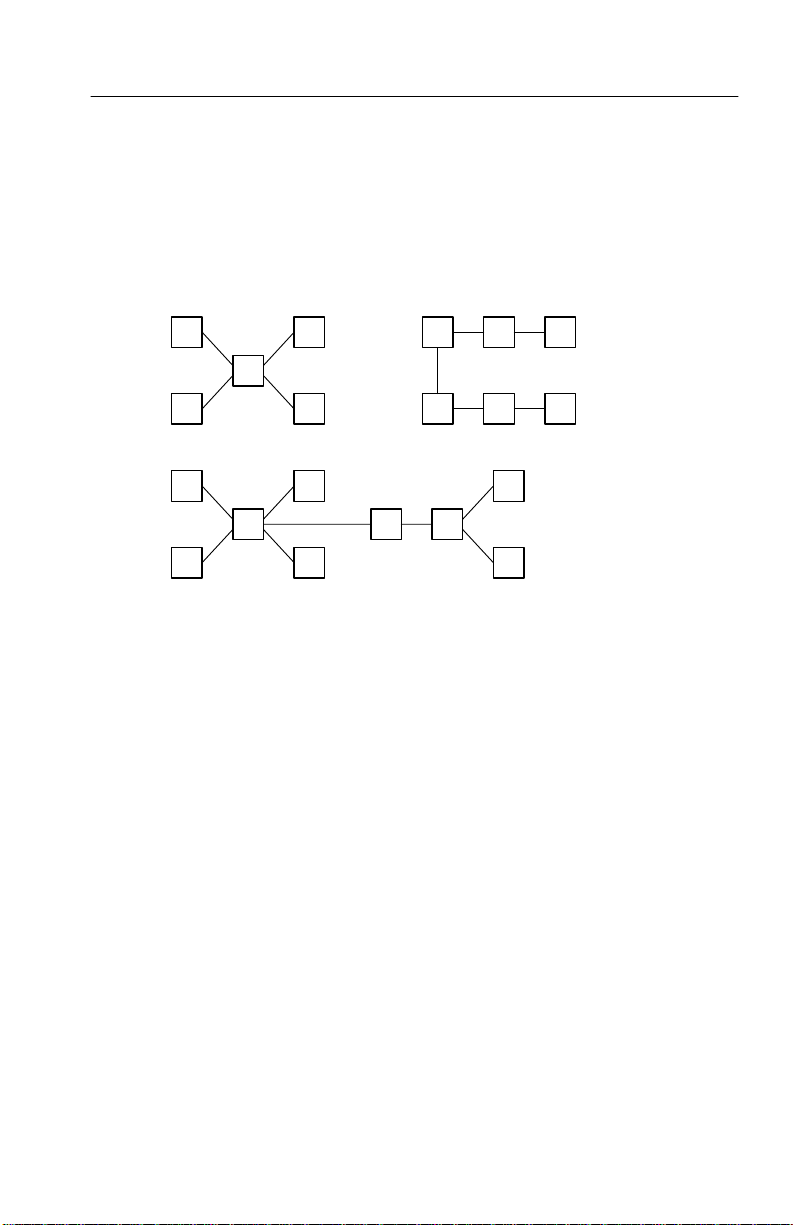
GPIB Network Conventions
Follow these guidelines when you assemble your GPIB network:
Connect the GPIB devices in a star, linear, or combination
star/linear network, as shown in the following figure.
TDS 200-Series Extension Module Instructions
25
Page 38

TDS2CM Communications Module
Do not use loop or parallel configurations (shown in the
following figure).
The maximum number of devices in a network is 15.
The maximum cable length between any two devices is 6.6 feet
(2 meters).
The maximum cable length in the entire network is 65 feet
(20 meters).
Assign a unique device address to each device on the network.
No two devices can share the same device address.
26
TDS 200-Series Extension Module Instructions
Page 39

TDS2MM Measurement Module
This section describes the operation of the TDS2MM Measurement
Extension Module. The TDS2MM Module includes all of the
communications capabilities of the TDS2CM Module (described
earlier in this manual), and adds the following measurement
capabilities:
Rise time, fall time, positive pulse width, and negative pulse
width (discussed in Signal Measurements, on page 29)
Fast Fourier Transform (FFT) (discussed in Using the FFT,
starting on page 30)
NOTE. To use the TDS2MM Module with a TDS 210 or TDS 220, be
sure that the oscilloscope has firmware version 1.06 or above.
to Read Me First on page 1 for more information.
Refer
TDS 200-Series Extension Module Instructions
27
Page 40

TDS2MM Measurement Module
Changed Operations for TDS 210 and TDS 220 with Firmware Below V 2.00
The TDS2MM Module when used with a TDS 210 or TDS 220
(firmware below V 2.00) changes the following math operations:
The TDS2MM Module does not have the CH1–CH2 and
CH2–CH1 math functions. T o do the same functions, invert the
channel you want to subtract (using the CH1 or CH2 menu) and
then select the CH1+CH2 math function.
Default channel
subtraction
CH1–CH2 CH1+(–CH2) (–CH2) means invert channel 2
CH2–CH1 (–CH1)+CH2 (–CH1) means invert channel 1
The TDS2MM Module moves the channel invert function from
the MATH menu to the Vertical CH1 and CH2 menus.
NOTE. For all other TDS 200-series oscilloscopes and firmware
versions, addition and subtraction operations do not change.
TDS2MM channel
subtraction
Comments
28
TDS 200-Series Extension Module Instructions
Page 41

Signal Measurements
Push the MEASURE button to display the automated measurement
menu. The new measurements are in the T ype menu. The TDS2MM
Module automatically determines the 10%, 50%, and 90% waveform
points.
Type Definition
Rise Time Measures the time between 10% and 90% of the first
Fall Time Measures the time between 90% and 10% of the first
Pos Width Measures the time between the first rising edge and the
Neg Width Measures the time between the first falling edge and the
TDS2MM Measurement Module
rising edge of the waveform. Rising edge must be
displayed to measure.
falling edge of the waveform. Falling edge must be
displayed to measure.
next falling edge at the waveform 50% level. Rising and
falling edges must be displayed to measure.
next rising edge at the waveform 50% level. Falling and
rising edges must be displayed to measure.
TDS 200-Series Extension Module Instructions
29
Page 42

TDS2MM Measurement Module
Using the FFT
The FFT process mathematically converts a time-domain signal into
its frequency components. FFT waveforms are useful in the
following applications:
T esting impulse response of filters and systems
Measuring harmonic content and distortion in systems
Characterizing noise in DC power supplies
Analyzing vibration
Analyzing harmonics in 50 and 60 Hz power lines
There are five steps to using the FFT:
1. Set up the source (time-domain) waveform
2. Display the FFT waveform
3. Select the FFT window type
4. Adjust the sample rate to display fundamental frequency and
harmonics without aliasing
30
5. Use zoom controls and the cursors to magnify and measure the
FFT waveform
TDS 200-Series Extension Module Instructions
Page 43

TDS2MM Measurement Module
Setting Up the Time-Domain Waveform
It is important to correctly set up the time-domain (YT) waveform to
produce a useable FFT waveform. Follow these steps to set up the
YT waveform:
1. Press AUTOSET to display a YT waveform.
2. Position the YT waveform vertically at center screen (zero
divisions) to get a true DC value. A standard FFT computation
yields a DC value that is twice as large as it should be with
respect to the other frequencies. The TDS2MM Module corrects
this error.
3. Position the YT waveform horizontally so that the waveform area
of interest is contained in the center eight divisions. The
TDS2MM Module uses the center 2048 points of the time-domain waveform to transform into an FFT waveform.
4. Set the YT waveform VOLTS/DIV so that the signal does not go
off screen. (Off screen waveform peaks can result in FFT
waveform errors).
5. Set the YT waveform SEC/DIV to provide the resolution you
want in the FFT waveform. It is important to show a number of
signal cycles if possible. Setting the time/division to a faster
setting means the FFT waveform shows a larger frequency range,
has less frequency resolution and reduces aliasing (refer to
Aliasing on page 39 for more information).
In many cases, you can produce a useful FFT waveform even if the
YT waveform is not triggered. This is especially true if your signal is
periodic or random (noisy). However, transient or burst waveforms
should be triggered and positioned as close as possible to center
screen.
TDS 200-Series Extension Module Instructions
31
Page 44

TDS2MM Measurement Module
Nyquist Frequency
The highest frequency that any real-time digitizing oscilloscope can
measure without errors is one-half the sample rate. This frequency is
called the Nyquist frequency. Frequency information above the
Nyquist frequency is undersampled, causing a situation known as
aliasing (refer to Aliasing on page 39).
The TDS2MM Module transforms the center 2048 points of the
time-domain waveform into an FFT waveform. The resulting FFT
waveform contains 1024 points that go from DC (0 Hz) to the
Nyquist frequency.
Normally , the display compresses the FFT waveform horizontally
into 250 points, but you can use the FFT Zoom function to expand
the FFT waveform to more clearly see the frequency components at
each of the 1024 data points in the FFT waveform.
NOTE. The oscilloscope bandwidth rolls off slowly above 20 MHz
(Bandwidth Limit ON), 60 MHz (TDS 210), or 100 MHz (TDS 220
and TDS 224). Therefore, the FFT waveform can show valid
frequency information higher than the oscilloscope bandwidth.
However, the magnitude information above the bandwidth will not be
accurate.
32
TDS 200-Series Extension Module Instructions
Page 45

TDS2MM Measurement Module
Displaying the FFT Waveform
Push the MATH button to display the math menu. Use the menu
buttons to select the FFT source channel, window algorithm, and
display magnification. You can display only one FFT waveform at a
time.
TDS 210 &
TDS 220 Menu*
CH1+CH2 Displays sum of channel 1 and 2 signals
FFT CH1 Switches between the channel 1 FFT and
FFT CH2 Switches between the channel 2 FFT and
Window Hanning
FFT Zoom X1
* Firmware below V 2.00.
Settings Comments
(refer to Changed Math Operations for
the TDS 210 and TDS 220 on page 28)
YT waveforms (selected = FFT)
YT waveforms (selected = FFT)
Selects the FFT window type
Flattop
Rectangular
Changes the horizontal magnification of
X2
X5
X10
the FFT display
TDS 200-Series Extension Module Instructions
33
Page 46
TDS2MM Measurement Module
TDS 210*, TDS 220*,
and TDS 224 Menu
Operation +, –, FFT Selects the math operation
Window Hanning
FFT Zoom X1
* Firmware V 2.00 and above.
† TDS 224 only.
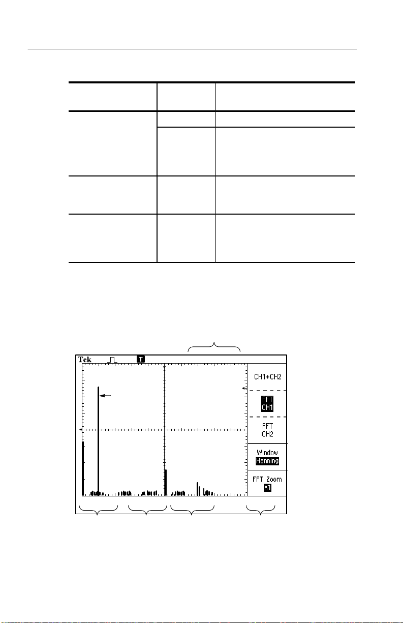
The FFT Display
Settings Comments
CH 1
CH 2
Selects the channel used as the FFT
source
CH 3†
CH 4†
Selects the FFT window type
Flattop
Rectangular
Changes the horizontal magnification
X2
of the FFT display
X5
X10
1
34
Frequency
component
234 5
TDS 210 and TDS 220, firmware below V 2.00
TDS 200-Series Extension Module Instructions
Page 47
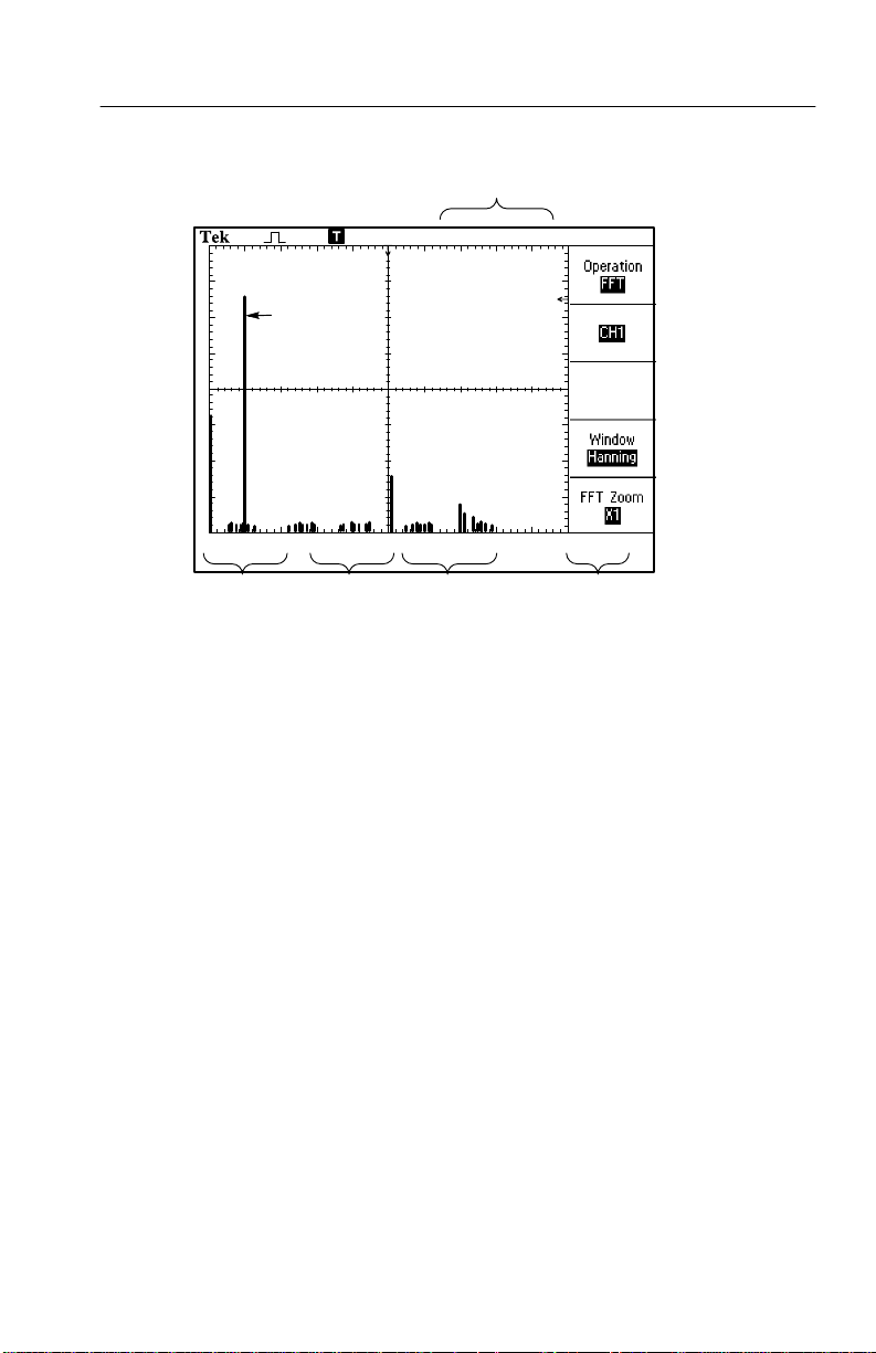
TDS2MM Measurement Module
1
Frequency
component
234 5
TDS 210 and TDS 220, firmware V 2.00 and above, and
TDS 224 firmware all versions
1. Frequency at the center graticule line
2. Vertical scale in dB per division (0 dB = 1 V
RMS
3. Horizontal scale in frequency per division
4. Sample rate in number of samples per second
)
5. FFT window type
TDS 200-Series Extension Module Instructions
35
Page 48

TDS2MM Measurement Module
FFT Windows
Windows reduce spectral leakage in the FFT waveform. The FFT
assumes that the YT waveform repeats forever. With an integral
number of cycles (1, 2, 3, ...), the YT waveform starts and ends at
the same amplitude and there are no discontinuities in the signal
shape.
A non-integral number of cycles in the YT waveform causes the
signal start and end points to be at different amplitudes. The
transitions between the start and end points cause discontinuities in
the signal that introduce high-frequency transients.
Time-domain
(YT) waveform
Center 2048
data points
36
Discontinuities
FFT
Without windowing
TDS 200-Series Extension Module Instructions
Page 49
TDS2MM Measurement Module
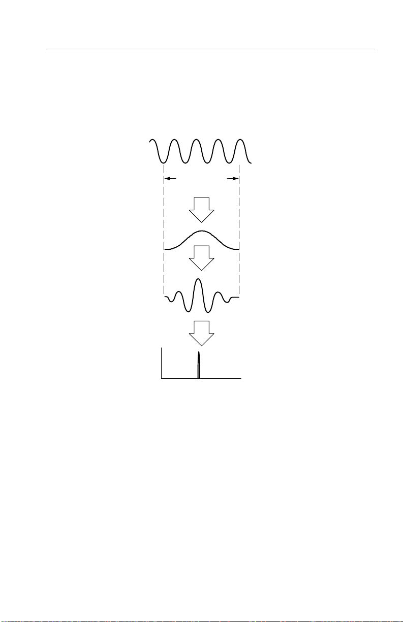
Applying a window to the YT waveform changes the waveform so
that the start and stop values are close to each other, reducing the
discontinuities.
Time-domain
(YT) waveform
Center 2048
data points
×
=
FFT
With windowing
Point-by-point
multiply
Window
function
(Hanning)
YT waveform
after windowing
TDS 200-Series Extension Module Instructions
37
Page 50

TDS2MM Measurement Module
Selecting an FFT Window
The TDS2MM Module provides three FFT windows. Each window
is a trade-off between frequency resolution and amplitude accuracy.
What you want to measure and your source signal characteristics
help determine which window to use. Use the following guidelines
to select the best window.
Window Measure Characteristics
Hanning Periodic
waveforms
Flattop Periodic
waveforms
Rectangular Pulses or
transients
Better frequency, poorer magnitude
accuracy than Flattop.
Better magnitude, poorer frequency
accuracy than Hanning.
Special-purpose window for waveforms that
do not have discontinuities. This is essentially the same as no window.
38
TDS 200-Series Extension Module Instructions
Page 51

TDS2MM Measurement Module
Aliasing
Problems occur when the oscilloscope acquires a time-domain
waveform containing frequency components that are greater than the
Nyquist frequency (refer to Nyquist Frequency on page 32). The
frequency components that are above the Nyquist frequency are
undersampled, appearing as lower frequency components that “fold
back” around the Nyquist frequency. These incorrect components are
called aliases.
Nyquist frequency
(one-half sample rate)
Amplitude
Frequency
Aliased frequencies Actual frequencies
TDS 200-Series Extension Module Instructions
39
Page 52

TDS2MM Measurement Module
Eliminating Aliases
Use the following methods to eliminate aliases:
Increase the sample rate by adjusting the time/division to a faster
setting. Since you increase the Nyquist frequency as you increase
the sample rate, the aliased frequency components should appear
at their proper frequency. If too many frequency components are
shown on the screen, use FFT Zoom to magnify the FFT
waveform.
Use a filter on the source signal to bandwidth limit the source
waveform to frequencies below that of the Nyquist frequency.
Recognize and ignore the aliased frequencies.
40
TDS 200-Series Extension Module Instructions
Page 53

TDS2MM Measurement Module
Horizontal Zoom and Position
The FFT Zoom menu lets you horizontally magnify the FFT
waveform without changing the sample rate. Zoom factors are X1
(default), X2, X5, and X10. At zoom factor X1, and with the
waveform centered in the graticule, the left graticule line is at 0 Hz
and the right graticule line is at the Nyquist frequency.
When you change the zoom factor, the FFT waveform is magnified
about the center graticule line. In other words, the axis of horizontal
magnification is the center graticule line.
The Horizontal Position knob moves the FFT waveform left or right
on the screen. Rotate the knob clockwise to move the waveform to
the right.
Vertical Zoom and Position
The channel vertical knobs become zoom and position controls for
their respective channels when displaying the FFT waveform. The
VOLTS/DIV knob provides zoom factors of X0.5, X1 (default), X2,
X5, and X10. The FFT waveform is vertically magnified about the
M marker (math waveform reference point on the left edge of the
display).
The Vertical Position knob moves the FFT waveform up or down on
the screen. Rotate the knob clockwise to move the waveform up.
TDS 200-Series Extension Module Instructions
41
Page 54

TDS2MM Measurement Module
Measuring FFT Waveforms Using Cursors
You can take two measurements on FFT waveforms: magnitude
(in dB) and frequency (in Hz). Magnitude is referenced to 0 dB,
where 0 dB equals 1 V RMS. You can use the cursors to take
measurements at any zoom factor.
Push CURSOR Source and select Math. Push the T ype menu
button to select between Magnitude and Frequency. Use the Vertical
Position knobs to move cursors 1 and 2.
Use horizontal cursors to measure magnitude and vertical cursors to
measure frequency. The menu boxes display the delta between the
two cursors, the value at cursor 1 position, and the value at cursor 2
position. Delta is the absolute value of cursor 1 minus cursor 2.
42
Magnitude cursors
Frequency cursors
You can also do a frequency measurement by using the Horizontal
Position knob to position a frequency component on the center
graticule line and read the frequency at the top right of the display.
TDS 200-Series Extension Module Instructions
Page 55

Appendix A: Certifications and Compliances
The TDS 200-Series Extension Modules meet the following
certifications and compliances.
Certifications and Compliances
EC Declaration of
Conformity
U.S. Certifications FCC 47 CFR Part 15, Subpart B, Class A
Australia/New Zealand
Declaration of
Conformity
Meets intent of Directive 89/336/EEC for Electromagnetic
Compatibility for Product Safety. Compliance was demonstrated
to the following specifications as listed in the Official Journal of
the European Communities:
EN 50081-1 Emissions:
EN 55011 Class A Radiated and Conducted
Emissions
EN 60555-2 AC Power Line Harmonic Emissions
EN 50082-1 Immunity:
IEC 801-2 Electrostatic Discharge Immunity
IEC 801-3 RF Electromagnetic Field Immunity
IEC 801-4 Electrical Fast Transient/Burst
Immunity
IEC 801-5 Power Line Surge Immunity
Meets intent of Australian Radiocommunications Act of 1992.
Compliance demonstrated and declared for the following
specification:
AS/NZS 2064.1/2 Industrial, Scientific, and Medical Equipment
TDS 200-Series Extension Module Instructions
43
Page 56

Appendix B: Comparing GPIB and RS-232
The following table provides an in-depth comparison of the GPIB
and RS-232 interfaces. You should select the interface that best
meets your requirements.
Operating Attribute GPIB RS-232
Cable IEEE-488 Std. 9-wire
Data flow control Hardware, 3-wire hand-
shake
Data format 8-bit parallel 8-bit serial
Interface control Operator low-level con-
trol message
Interface messages Most IEEE-488 Std. Device clear using a
Interrupts reported Service requests, status
and event code
Flagging:
soft (XON/XOFF),
hard (RTS/CTS)
None
break signal
None, must be polled for
status
44
TDS 200-Series Extension Module Instructions
Page 57

Appendix B: Comparing GPIB and RS-232
Operating Attribute RS-232GPIB
Message termination
(Receive)
Message termination
(Transmit)
Timing Asynchronous Asynchronous
Transmission path length
(max)
Speed 200 kBytes/sec 19,200 bits/sec
System environment Multiple devices (≤ 15) Single terminal (point-to-
Hardware EOL,
software LF, or both
Hardware EOL, softwareLFSoftware CR, LF, CRLF,
≤ 2 meters between
devices; ≤ 20 meters
total cabling
Software CR, LF, CRLF,
LFCR
LFCR
≤ 15 meters
point connection)
TDS 200-Series Extension Module Instructions
45
Page 58

Appendix C: Manuals
TDS 200-Series Digital Oscilloscope Service Manual. The
service manual (071-0492-XX, English) provides module level
repair information.
TDS 200-Series Digital Oscilloscope User Manuals. The
User manual is available in these languages:
English 071-0398-XX
French 071-0400-XX
Italian 071-0401-XX*
German 071-0402-XX*
Spanish 071-0399-XX*
Japanese 071-0405-XX*
Portuguese 071-0403-XX*
Simplified Chinese 071-0406-XX *
Traditional Chinese 071-0407-XX*
TDS 210 & TDS 220
Korean 071-0408-XX*
Russian 071-0404-XX
*These manuals contain a language overlay for the front-panel controls.
TDS 200-Series Extension Module Instructions. The
module instructions are available in these languages:
*
46
TDS 224
English 071-0409-XX
French 071-0483-XX
Italian 071-0484-XX
German 071-0485-XX
Spanish 071-0482-XX
Japanese 071-0488-XX
Portuguese 071-0486-XX
Simplified Chinese 071-0489-XX
Traditional Chinese 071-0490-XX
Korean 071-0491-XX
Russian 071-0487-XX
TDS 200-Series Extension Module Instructions
Page 59

Appendix C: Manuals
TDS 200-Series Digital Oscilloscope Programmer Manual.
The programmer manual (English 071-0493-XX) provides
command syntax for remote control of the TDS 200-Series
oscilloscope.
TDS 200-Series Extension Module Instructions
47
Page 60

Appendix C: Manuals
48
TDS 200-Series Extension Module Instructions
 Loading...