

Page 1

xx
TBS1000 Series
ZZZ
Digital Storage Oscilloscopes
Service Manual
*P077077201*
077-0772-01
Page 2

Page 3

xx
TBS1000 Series
ZZZ
Digital Storage Oscilloscopes
Service Manual
Revision B (20161230)
This document applies to TBS1000 models with no display
adapter module.
Warning
The servicing instructions are for use by qualified personnel
only. To avoid personal injury, do not perform any servicing
unless you are qualified to do so. Refer to all safety summaries
prior to perform ing service.
www.tek.com
077-0772-01
Page 4

Copyright © Tektronix. All rights reserved. Licensed software products are owned by Tektronix or its subsidiaries
or suppliers, and are protected by national copyright laws and international treaty provisions.
Tektronix products are covered by U.S. and foreign patents, issued and pending. Information in this publication
supersedes that in all previously published m aterial. Specifications and price change privileges reserved.
TEKTRONIX and TEK are registered trademarks of Tektronix, Inc.
OpenChoice is a registered trademark of Tektronix, Inc.
Contacting Tektronix
Tektronix, Inc.
14150 SW Karl Braun Drive
P.O . Box 5 00
Beaverton, OR 97077
USA
For product information, sales, service, and technical support:
In North America, call 1-800-833-9200.
Worldwide, visit www.tektronix.com to find contacts in your area.
Page 5

Table of Contents
General safety summary .................. .................................. .................................. .... vi
Service safety summary.......................................................................................... viii
Preface.............................................................................................................. ix
Manual Conventions.............................. .................................. .......................... ix
Related Documentation ...................................................................................... ix
Specifications
Specifications ........ .................................. ................................ ........................... 1-1
Signal Acquisition System Characteristics.. .. ... . . . ... . . . ... . .... .. ... . . . ... . .... .. ... . .... .. ... . . . ... . .. 1-1
Time Base System .. .................................. .................................. ..................... 1-6
Triggering System ........ .................................. .................................. ............... 1-8
Display Specifications........................ ................................ ............................. 1-12
Interfaces and Output Ports Specifications.............................................................. 1-13
Data Handling Characteristics........... .................................. ............................... 1-13
Power Distribution System ............................................................................... 1-13
Mechanical Characteristics ............................................................................... 1-14
Environmental Performance.............................................................................. 1-14
Data Logging System Characteristics ................................................................... 1-14
Limit Testing System Characteristics. .. . . ... . . . ... . .... .. ... . . . ... . . . ... . .... .. ... . . . ... . .... .. ... . . . ... 1-15
WheretoFindOperatingInformation
Where to Find Operating Information........................................... ............................... 2-1
Theory of Operation
Theory of Operation..................... ................................ .................................. ....... 3-1
System Level Block Diagrams .................. .................................. ......................... 3-1
Main Board................................................................................................... 3-3
Acquisition System .. . ... . .. ... . . . ... . . . ... . . . ... . . . ... . . . ... . .. ... . . . ... . . . ... . . . ... . . . ... . .. ... . . . ... . 3-3
Processing and Display System ...... .................................. ............................... 3-4
Input Signal Interface.............................. ................................ ..................... 3-4
Probe Compensation....... .................................. .................................. ......... 3-4
External Trigger ......................................................................................... 3-4
Main Board Power ...................................................................................... 3-4
Power Supply................................................................................................. 3-4
Display Module . .................................. ................................ ........................... 3-5
Front Panel ................ .................................. .................................. ............... 3-5
Two-Channel Oscilloscopes ... .. ... . ... . . . ... . ... . . . ... . ... . . . ... . ... . . . ... . ... . . . ... . ... . . . ... . ... . . . 3-5
TBS1000 Series Oscilloscope Service Manual i
Page 6

Table of Contents
Four-Channel O
scilloscopes ... . ... . .. ... . . . ... . . . ... . . . ... . . . ... . . . ... . . . ... . . . ... . . . ... . . . ... . . . ... . . 3-5
Performance Verification
Performance Verification . .................................. .................................. ................... 4-1
Required Equipment......................................................................................... 4-1
Test Record .................. .................................. ................................ ............... 4-2
Performance Verification Procedures ...................................................................... 4-3
Self Test.................................................................................................. 4-3
Self Calibration................. ................................ .................................. ....... 4-3
Check DC Gain Accur
Check Bandwidth ...................... .................................. ............................... 4-5
Check Sample Rate Accuracy and Delay Time Accuracy................................... ....... 4-6
Check Edge Trigger Sensitivity .... .................................. ................................ . 4-7
Check External Edge Trigger Sensitivity............................................ ................. 4-9
Check Vertical Position Accuracy.. .. ... . .. ... . . . ... . . . ... . . . ... . . . ... . .. ... . . . ... . . . ... . . . ... . . . ... 4-10
Adjustment Procedures
Adjustment Procedures .......................................................................................... 5-1
Required Equipment......................................................................................... 5-1
Adjustment Procedure....................................................................................... 5-1
Enable the Service Menu.................... ................................ ........................... 5-2
Adjustment Procedure ........................... .................................. ..................... 5-4
Maintenance....................................................................................................... 6-1
Preventing ESD .............................................................................................. 6-1
Inspection and Cleaning...................... ................................ ............................... 6-1
General Care............................................................................................. 6-2
Interior Cleaning ........................................................................................ 6-2
Exterior Cleaning ................ .................................. .................................. ... 6-2
Exterior Inspection................... .................................. ................................. 6-3
Interior Inspection ....... ................................ .................................. ............. 6-3
Cleaning Procedure, Interior
Removal and Installation Procedures..................... .................................. ............... 6-6
Summary of Procedures................. .................................. ............................. 6-6
Required Tools ... ................................ .................................. ..................... 6-8
Rear Feet .................... ................................ .................................. ........... 6-8
Flip Feet.................................................................................................. 6-9
Front-Panel Knobs...................................................................................... 6-9
Power Button ..................... .................................. ................................ ..... 6-9
Rear Case .............................................................................................. 6-10
Front Feet ............................. .................................. ............................... 6-11
acy........... .................................. ................................. 4-3
........................ ................................ ................... 6-4
ii TBS1000 Series Oscilloscope Service Manual
Page 7

Table of Contents
Power Supply Mo
Internal Assembly.................................... .................................. ............... 6-13
Front-Panel Cable.................. ................................ .................................. . 6-15
Main Board Module (without the Display Adapter Module) ......... ........................... 6-16
Display Module ....................................................................................... 6-19
Front-Panel Module................................ ................................ ................... 6-20
Keypad .............. ................................ .................................. ................. 6-21
Troubleshooting................................. ................................ ........................... 6-22
Adjustment After Repair ............................................................................. 6-22
Required Tools and Equipment........................................... ........................... 6-22
Troubleshooting Tree................................................................................. 6-22
Probe Comp Output.... ................................ .................................. ............. 6-27
Trouble
Troubleshooting the Display......................................................................... 6-29
Troubleshooting the Front Panel ......... .................................. ......................... 6-30
Troubleshooting the Main Board. .................................. ................................. 6-33
Repackaging Instructions .................... .................................. ........................... 6-36
Diagrams .......................................................................................................... 7-1
shooting the Power Supply ...... ................................ ........................... 6-28
dule................................................................................ 6-12
Replaceable Parts
Replaceable Parts................................................................................................. 8-1
Parts Ordering Information ................................................................................. 8-1
Using the Replaceable Parts List........................................................................... 8-2
rts Lists and Exploded Views............................................................................ 8-3
Pa
Appendix A: Example of a Ve rtical Position Accuracy Test Spreadsheet.. . ... . .... .. ... . . . ... . .... .. ... . A-1
Sample Filled-In Vertical Position Accuracy Test Spreadsheet. . ... . ... . .. ... . ... . .. ... . .... .. ... . .... A-1
TBS1000 Series Oscilloscope Service Manual iii
Page 8

Table of Contents
List of Figure
Figure 3-1: Module-level block diagram (2-channel) ........................................................ 3-1
Figure 3-2:
Figure 4-1: Example of a line graph for the Vertical Position Accuracy test .. . . . ... . .... .. ... . . . ... . . . . 4-13
Figure 5-1: Adjustment setups.................................................................................. 5-3
Figure 6-1: Locator for trim and cabinet removal (2-channel model shown).............................. 6-7
Figure 6-2: Locator for internal modules (2-channel model shown) ....................................... 6-7
Figure 6-3: Main board with the Display Adapter (refer to: Service Manual 077-0772-00) .......... 6-14
Figure 6-
Figure 6-5: Oscilloscope troubleshooting tree (page 1 of 4)... .. ... . . . ... . . . ... . . . ... . . . ... . . . ... . .... .. .. 6-23
Figure 6-6: Oscilloscope troubleshooting tree (page 2 of 4)... .. ... . . . ... . . . ... . . . ... . . . ... . . . ... . .... .. .. 6-24
Figure 6-7: Oscilloscope troubleshooting tree (page 3 of 4)... .. ... . . . ... . . . ... . . . ... . . . ... . . . ... . .... .. .. 6-25
Figure 6-8: Oscilloscope troubleshooting tree (page 4 of 4)... .. ... . . . ... . . . ... . . . ... . . . ... . . . ... . .... .. .. 6-26
Figure 7-1: TBS1000 series block diagram ................................................................... 7-2
Figur
Figure 8-2: Exploded diagram, 4-channel models ................. .................................. ......... 8-6
Figure 8-3: Power supply module, cables, and wires.......................... ............................... 8-8
Figure 8-4: Exploded diagram, back case and trim.................. .................................. ..... 8-10
Module-level block diagram (4-channel) ........................................................ 3-2
4: Instrument cable locations (Main Board without the Display Adapter Module) .. . . . .... . 6-17
e 8-1: Exploded diagram, 2-channel models............................................................ 8-3
s
iv TBS1000 Series Oscilloscope Service Manual
Page 9

List of Tables
Table 1-1: Signal acquisition system characteristics . .. ... . .. ... . . . ... . .... .. ... . . . ... . . . ... . . . ... . . . ... . . . .. 1-1
Table 1-2: T
Table 1-3: Triggering system.................................................................................... 1-8
Table 1-4: Display specifications .................... .................................. ....................... 1-12
Table 1-5: Interfaces and output ports specifications.................... ................................ ... 1-13
Table 1-6: Data handling characteristics ..................................................................... 1-13
Table 1-7: Power distribution system ....... .................................. ............................... 1-13
Table 1-8
Table 1-9: Environmental performance ...................................................................... 1-14
Table 1-10: Data logging system characteristics....................... .................................. ... 1-15
Table 1-11: Limit testing system characteristics . .. ... . .. ... . ... . .. ... . .... .. ... . . . ... . ... . .. ... . .... .. ... . . 1-15
Table 4-1: Performance verification ..................... .................................. ..................... 4-1
Table 4-2: Test record ............................................................................................ 4-2
Table
Table 5-2: Adjustment steps..................................................................................... 5-5
Table 6-1: External inspection checklist ....................................................................... 6-3
Table 6-2: Internal inspection checklist....................... ................................ ................. 6-4
Table 6-3: Tools and equipment ........... .................................. ................................. 6-22
Table 6-4: Probe Comp output................... ................................ ............................. 6-27
ble 6-5: Troubleshooting the power supply...................... ................................ ......... 6-28
Ta
Table 6-6: Troubleshooting the front panel – service....................................................... 6-30
Table 6-7: Troubleshooting the front panel – Service Diag..................................... ........... 6-30
Table 6-8: Troubleshooting the front panel – Mfg. test.................................................... 6-30
Table 6-9: Expected signals at J202 .......................................................................... 6-31
Table 6-10: Troubleshooting the Main board..................... .................................. ......... 6-33
Table 6-11: List of error codes ................................................................................ 6-34
Table 8-1: Replaceable parts list........... .................................. .................................. . 8-2
Table 8-2: Replaceable parts list, 2-channel models........................................... ............... 8-4
Table 8-3: Replaceable parts list, 4-channel models........................................... ............... 8-7
Table 8-4: Replaceable parts list; power supply module, instrument cables, and wires ............... ... 8-8
Table 8-5: Replaceable parts list, back case and trim ............. ................................ ......... 8-11
Table A-1: Vertical position accuracy test spreadsheet. . .... .. ... . .... .. ... . .... .. ... . .... .. ... . .... .. ... . .. A-1
ime base system ......................... .................................. ......................... 1-6
: Mechanical characteristics................. .................................. ..................... 1-14
5-1: Required equipment ...... .................................. .................................. ....... 5-1
Table of Contents
TBS1000 Series Oscilloscope Service Manual v
Page 10

General safety summary
General safet
To avoid fir
e or personal
injury
ysummary
Review the fo
this product or any products connected to it.
To avoid pot
Only qualified personnel should perform service procedures.
Use proper
certified for the country of use.
Connect a
instrument before connecting the probe to the circuit under test. Connect the
probe reference lead to the circuit under test before connecting the probe input.
Disconnect the probe inpu t and the probe reference lead from the circuit under test
before disconnecting the probe from the measurement instrument.
Ground the product. This product is grounded through the grounding conductor
of the power cord. To avoid electric shock, the grounding conductor must be
connected to earth ground. Before making connections to the input or output
nals of the product, ensure that the product is properly grounded.
termi
Observe all terminal ratings. To avoid fire or shock hazard, observe all ratings
arkings on the product. Consult the product manual for further ratings
and m
information before making connections to the product.
llowing safety precautions to avoid injury and prevent damage to
ential hazards, u se this product only as specified.
power cord. Use only the power cord specified for this product and
nd disconnect properly. Connect the probe output to the measurement
nect the probe reference lead to earth ground only.
Con
Do not apply a potential to any terminal, including the comm o n terminal, that
eeds the maximum ratingofthatterminal.
exc
Power disconnect. The power switch disconnects the product from the power
urce. See instructions for the location. Do not block the power switch; it must
so
remain accessible to the user at all times.
o not operate without covers. Do not operate this product with covers or panels
D
removed.
Do not operate with suspected failures. If you suspect that there is damage to this
product, have it inspected by qualified service personnel.
Avoid exposed circuitry. Do not touch exposed connections and components when
power is present.
vi TBS1000 Series Oscilloscope Service Manual
Page 11

General safety summary
Terms in this manual
Symbols and terms on the
product
Do not operate i
Do not operate in an explosive atmosphere.
Keep product surfaces clean and dry.
Provide prop
on installing the product so it has proper ventilation.
These terms may a ppear in this manual:
WAR N ING.
in injury or loss of life.
CAUTION
damage to this product or other property.
These t
erms may appear on the product:
DANGER indicates an injury hazard immediately accessible as you read
the ma
n wet/damp conditions.
er ventilation. Refer to the manual's installation instructions for details
Warning statements identify conditions or practices that could result
. Caution statements identify conditions or practices that could result in
rking.
WARNING indicates an injury hazard not immediately accessible as you
the marking.
read
CAUTION indicates a hazard to property including the product.
The following symbol(s) may appear on the product:
TBS1000 Series Oscilloscope Service Manual vii
Page 12

Service safety summ a ry
Service safet
ysummary
Only qualifie
safety summary and the General safety summary before performing any service
procedures.
Do not service alone. Do not perform internal service or adjustments of this
product unless another person capable of rendering first aid and resuscitation is
present.
Disconnect power. To avoid electric shock, switch off the instrument power, then
disconnect the power cord from the mains power.
Use care when servicing with power on. Dangerous voltages or currents may exist
in this p
test leads before removing protective panels, soldering, or replacing components.
To avoi
d personnel should perform service procedures. Read this Service
roduct. Disconnect power, remove battery (if applicable), and disconnect
d electric shock, do not touch exposed connections.
viii TBS1000 Series Oscilloscope Service Manual
Page 13

Preface
Manual Conventions
This service manual provides information to verify performance of, calibrate,
troubleshoot, disassemble, and replace parts on the TBS1000 Series Digital
Storage Osci
Unless noted otherwise, the term "oscilloscope" refers to all models in the
TBS1000 ser
lloscopes.
ies.
Modules
Replaceable Parts
Safety
Related Documentation
This manu
before attempting service.
Throughout this manual, any replaceable component, assembly, or part is referred
to by the
A module is composed of electrical and mechanical assemblies, circuit cards,
interc
This manual refers to any field-replaceable assembly or mechanical part
specifically by its name or generically as a replaceable part. In general, a
aceable part is any circuit board or assembly, such as the hard disk drive, or a
repl
mechanical part, such as the I/O port connectors, that is listed in the replaceable
parts list.
Sym
at the beginning of this manual.
al uses certain conventions that you should become familiar with
term module.
onnecting cables, and user-accessible controls.
bolsandtermsrelatedtosafetyappearintheServiceSafetySummaryfound
To read about Use these documents
nstallation and
I
Operation
Programmer
Commands
TBS1000 Series Oscilloscope Service Manual ix
he oscilloscope user manual, available on the Tektronix Web
T
site.Go to www.tektronix.com/manuals and search for the user
manual for your product (available in 11 languages).
The oscilloscope programmer manual, available on the Tektronix
Web site. Go to www.tektronix.com/manuals and search for the
programmer m anual for your product.
Page 14

Preface
x TBS1000 Series Oscilloscope Service Manual
Page 15

Specifications
Page 16

Page 17

Specifications
These specifications apply to all TBS1000 series oscilloscopes. To verify that an
oscilloscope meets specifications, it must first meet the following conditions:
The oscilloscope must have been operating continuously for twenty minutes
within the specified ope rating temperature.
You must perform the Do Self Cal operation, accessible through the Utility
menu, if the operating temperature has changed by more than 5 °C (9 °F)
since the l
The oscilloscope must be within the factory calibration interval of o ne year.
Specifications are provided in the following tables. All specifications are
guaranteed unless noted "typical." Specifications that are marked with the symbol
are chec
Ver ification.)
Signal Acquisition System Characteristics
NOTE. All amplitude-related or modified speci fications require 1X probe
attenuation factors unless otherwise specified. This is due to the way the displayed
itivity works. This does not affect actual methods of attachment. It only alters
sens
the relationship between displayed scale factors and the specifications.
ast time the Do Self Cal operation w as performed.
ked in the Performance Verification section. (See page 4-1, Performance
le 1-1: Signal acquisition system characteristics
Tab
cription
Characteristic
Number of Input
Channels
Input Coupling DC, AC, or GND
Input Impedance, DC
Coupled
Des
TBS1152
TBS1102
S1062
TB
TBS1042
TBS1022
BS1154
T
TBS1104
TBS1064
1MΩ ±2%inparallelwith20pF±3pF
nominally identical channels, sampled
Two
simultaneously.
Four nominally identical channels, sampled
imultaneously
s
TBS1000 Series Oscilloscope Service Manual 1–1
Page 18

Specifications
Table 1-1: Signal acquisition system characteristics (cont.)
Characteristic
Maximum Input Voltage
Description
At the front panel connector, 300 V
, Installation Category II; derate at 20 dB/decade above 100 kHz to
RMS
13 V peak AC at 3 MHz and above.
Based on sinusoidal or DC input signal. The maximum viewable signal while DC coupled is ±50 V offset
±5 V/div at 4 divisions, or 70 V. AC coupling allows measuring signals on a DC level up to 300 V. For
nonsinusoidal waveforms, peak value must be less than 450 V. Excursions above 300 V should be less
than 100 ms in duration, and the duty factor is limited to < 44%. The RMS signal level must be limited to
300 V. If these values are exceeded, damage to the instrument may result.
8 bits except at 2 mV/divNumber of Digitized B its
Displayed vertically with 25 digitization levels per division, 10 divisions dynamic range.
2 mV/div setting is generated by digital multiplication and the resolution is reduced. Given 100 levels
available, the resolution is >6.5 bits.
Sensitivity Range 2 m V/div to 5 V/div in 1-2-5 sequence with the probe attenuation set to 1X.
Display Gain Variable
The Display Gain Variable function allows the user to vary the vertical display gain continuously over the
full range.
Resolution is that of the coarse gain from which these data are constructed. Fine gain values (for
instance 120 mV/div) are acquired at the next higher coarse gain setting (in this case 200 mV/div).
The Display Gain Variable is achieved by digital multiplication of the data to obtain the settings between
the 1-2-5 gain settings.
Hard copy outputs to printer will be exactly the same as seen on screen even when the Display Gain
Variable is used.
However, WAVEFORM DATA obtained through the I/O interface is limited to the 1-2-5 gain settings.
Probe Scale Factors
1X, 10X, 20X, 50X, 100X, 500X, 1000X voltage attenuation.
5, 1, 500 m, 200 m, 20 m, 10 m, 1 m V/A current scale factor.
This adjusts the display scale factor of the instrument to accommodate various probe types.
Accuracy of the probe used must be added to the accuracy specifications of instrument.
No automatic probe interface is provided, so you must verify that the settings match the probe
characteristics. The probe check function allows setting of the proper attenuation for voltage probes.
Acquisition Modes
Sample, Peak Detect, Average
Envelope mode not provided
Retained Front Panel
Settings
Front panel settings are retained when the instrument power is turned off and on with the power switch.
The settings are retained when the line power is turned off and on.
The instrument periodically saves front panel se ttings after settings are changed. There is a delay of
three seconds after the last change and before the storage of the settings in memory.
1–2 TBS1000 Series Oscilloscope Service Manual
Page 19

Table 1-1: Signal acquisition system characteristic s (cont.)
Specifications
Characteristic
Math Modes
Voltage Measurement
Functions
√ DC Gain Accuracy,
Sample or Average
Acquisition
DC Voltage
Measurement Accuracy,
Average Acquisition
Mode
Delta Volts Measurement
Accuracy, Average
Acquisition Mode
Analog Bandwidth
Description
All Units:
Channel 1 – Channel 2
Channel 2 – Channel 1
Channel 1 + Channel 2
Channel 1 * Channel 2 FFT
4 channel units (TBS1154, TBS1104, TBS1064)
Channel 3 – Channel 4
Channel 4 – Channel 3
Channel 3 + Channel 4
Channel 3 * Channel 4
Mean, Cyc RMS, Peak-to-Peak, Max, Min, RMS, CursorRMS
This is the difference between the measured DC gain and the nominal DC gain, divided by the nominal
DC gain and expressed as a percent.
±3%, 5 V/div through 10 mV/div
±4%, 5 mV/div and 2 mV/div
Vertical position = 0: ±(3% of |reading| + 0.1 div + 1 mV)
Vertical position ≠ 0 and vertical scale = 2 mV/div to 200 mV/div: ±[3% of |reading + vertical position|
+ 1% of |vertical position| + 0. 2 div + 7 m V]
Vertical position ≠ 0 and vertical scale > 200 mV/div: ±[3% of |reading + vertical position| + 1% of
|vertical position| + 0.2 div + 175 mV]
Delta volts between any two averages of 16 waveforms acquired under the s ame setup and ambient
conditions.
(3% of |reading| + 0.05 div)
Defined in Section 4.6 of IEEE std 1057. The difference between the upper and lower frequencies, at
which the amplitude response, as seen in the data record, is 0.707 (-3 dB) of the response seen in the
data record at the specified reference frequency. Specifies only the -3 dB point. It does not include
the in-band response.
TBS1000 Series Oscilloscope Service Manual 1–3
Page 20

Specifications
Table 1-1: Signal acquisition system characteristics (cont.)
Characteristic
√ Analog Bandwidth,
DC Coupled, Sample or
Average
Analog Bandwidth, DC
Coupled, Peak Detect,
typical
Analog Bandwidth
Selections
Upper-Frequency Limit,
20 MHz Bandwidth
Limited, typical
Description
This is analog bandwidth when the instrument is DC coupled in sample or average mode. V/div values
are accurate for probe attenuation settings of 1X. No probe should be installed for these measurements.
System bandwidth is type tested to be equivalent to this specification with the provided probe in 10X
mode. Use Section 4.6.1 of IEEE 1057, with the reference frequency of 1 kHz at an amplitude of
5 divisions, driven from a 50 Ω source with external termination at the input BNC (25 Ω effective source).
TBS1154, TBS1152:
DC to ≥ 150 MHz for 5 mV/div through 5 V/div settings with bandwidth limit at full. < 5 mV/div settings
are limited to 20 MHz bandwidth.
TBS1104, TBS1102:
DC to ≥ 100 MHz for 5 mV/div through 5 V/div settings with bandwidth limit at full. < 5 mV/div settings
are limited to 20 MHz bandwidth.
TBS1064, TBS1062:
DC to ≥ 60 MHz for 5 mV/div through 5 V/div settings with the bandwidth limit at full. < 5 MV/div settings
are limited to 20 MHz bandwidth.
TBS1042:
DC to ≥ 40 MHz for 5 mV/div through 5 V/div settings with the bandwidth limit at full. < 5 mV/div settings
are limited to 20 MHz bandwidth.
TBS1022:
DC to ≥ 25 MHz for 5 mV/div through 5 V/div settings with bandwidth limit at full. < 5 mV/div settings are
limited to 20 MHz bandwidth.
This is the analog bandwidth when th e instrument is DC coupled. V/div values are accurate for probe
attenuation settings of 1X. No probe should be installed for these measurements.
TBS1154, TBS1152, TBS1104, TBS1102:
DC to ≥ 75 MHz for 5 mV/div through 5 V/div settings with the bandwidth limit at full. Settings less
than 5 mV/div are limited to 20 MHz bandwidth.
TBS1064, TBS1062:
DC to ≥ 50 MHz for 5 mV/div through 5 V/div settings with the bandwidth limit at full. Settings less
than 5 mV/div are limited to 20 MHz bandwidth.
TBS1042:
DC to ≥ 30 MHz for 5 mV/div through 5 V/div settings with the bandwidth limit at full. Settings less
than 5 mV/div are limited to 20 MHz bandwidth.
TBS1022:
DC to ≥ 20 MHz for 5 mV/div through 5 V/div settings with the bandwidth limit at full.
20 MHz bandwidth limit ON/OFF
This is the upper frequency for Analog Bandwidth when the instrument has 20 MHz bandwidth limiting
turned on.
20 MHz
Bandwidth of all trigger paths are similarly limited, except the External Trigger, which is not affected
by BW Limit function. Each channel is separately limited, allowing different bandwidths on different
channels of the same instrument.
1–4 TBS1000 Series Oscilloscope Service Manual
Page 21

Table 1-1: Signal acquisition system characteristic s (cont.)
Specifications
Characteristic
Lower- Frequency Limit,
AC Coupled
Rise Time, typical
Peak Detect Mode Pulse
Response
Description
This is the lower frequency for Analog Bandwidth when the instrument is AC-coupled
≤ 10 Hz.
<1 Hz when 10X, passive probes are used.
Model
TBS1154, TBS1152
TBS1104, TBS1102
TBS1064, TBS1062
TBS1042
TBS1022
Rise time is generally calculated from the following formula: Rise time in ns = 350 / Bandwidth in MHz
This is the capability of the instrument to capture single event pulses using the Peak Detect Acquisition
Mode.
The minimum single pulse widths for guaranteed 50% or greater amplitude capture are as follows:
Model
TBS1154
TBS1152
TBS1104
TBS1102
TBS1064
TBS1062
Expected full bandwidth rise time
2.6 ns
3.5 ns
6.0 ns
8.8 ns
14.0 ns
Sec/Div Setting
50 sec/div to 5 μS/div
Minimum Pulse Width
12 ns
Vertical Position Ranges
√ Vertical Position
Accuracy
TBS1042
TBS1022
These are the ranges of the user-settable input offset voltage.
Volts/Div Setting
2 mV/div to 200 mV/div
> 200 m V /div to 5 V/div
This is the accuracy of the nominal voltage level represented by the code at the vendor of the A-D
converter's dynamic range.
Volts/Div Setting
2 mV/div to 200 mV/div ±(1% of |selected value| + 0.1 div + 5 mV) within the
> 200 mV/div to 5 V/div ±(1% of |selected value| + 0.1 div + 125 mV) within the
50 sec/div to 5 μS/div
Position Range
±1.8V
±45V
Position Accuracy
range ±1.8 V
range ±45 V
13 ns
TBS1000 Series Oscilloscope Service Manual 1–5
Page 22

Specifications
Table 1-1: Signal acquisition system characteristics (cont.)
Common Mode
Rejection Ratio (CMRR),
typical
Crosstalk (Channel
Isolation)
With the same signal applied to each channel, CMRR is the ratio of the acquired signal amplitude to the
amplitude of the MATH difference waveform, either (Channel 1 - Channel 2), (Channel 2 - Channel 1)
Model
TBS1154
TBS1152
TBS1104
TBS1102
TBS1064
TBS1062
TBS1042
TBS1022
Section 4.11.1 of IEEE std. 1057. It is the ratio of the level of a signal input into one channel to that of
the s ame signal present in another channel due to stray coupling.
Model
TBS1154, TBS1152 ≥ 100:1 with a 75 MHz sine wave and with equal V/div settings on each
TBS1104, TBS1102 ≥ 100:1 with a 50 MHz sine wave and with equal V/div settings on each
TBS1064, TBS1062 ≥ 100:1 with a 30 MHz sine wave and with equal V/div settings on each
TBS1042 ≥ 100:1 with a 20 MHz sine wave and with equal V/div settings on each
TBS1022 ≥ 100:1 with a 10 MHz sine wave and with equal V/div settings on each
Common Mode Rejection Ratio
100:1 at 60 Hz, reducing to 10:1 with 50 MHz sine wave, with equal
Volts/Div and Coupling settings on each channel.
100:1 at 60 Hz, reducing to 20:1 with a sine wave with frequency equal to
½ the -3 dB bandwidth and with equal Volts//Div and Coupling settings
on each channel.
Crosstalk
channel
channel
channel
channel
channel
Time Base System
Table 1-2: Time base system
Characteristic
Sample-Rate Range
1–6 TBS1000 Series Oscilloscope Service Manual
Description
This is the range of real-time rates, expressed in samples/second, at which a digitizer samples signals at
its inputs and stores the samples in memory to produce a record of time-sequential samples. ( IEEE
1057, 2.2.1)
Model
TBS1154, TBS1152
TBS1104, TBS1102
TBS1064, TBS1062
TBS1042
TBS1022
Sample-rate range
5 S/s to 1000 MS/s
5 S/s to 500 MS/s
Page 23

Table 1-2: Time b ase system (cont.)
Specifications
Characteristic
Record Length
√ Long-Term Sample
Rate and Horizontal
Position Time Accuracy
Horizontal Position Time
Range
Horizontal Window
Display
Delta Time Measurement
Accuracy
Time Measurement
Functions
Description
(Sin x)/x interpolationWaveform Interpolation
Waveform interpolation is activated for sweep speeds of 100 ns/div and faster.
This is the total number of samples contained in a single acquired waveform record (Memory Length in
IEEE 1057.2.2.1).
2,500 samples per record.
5 ns/div to 50 s/div in 1–2.5–5 sequenceSeconds/Division Range
Sec/Div Variable function is not available for this product.
This is the maximum, total, long-term error in sample-rate or horizontal position time accuracy, expressed
in parts per million.
±50 ppm over any ≥1 ms interval.
Horizontal scale setting Horizontal position time range
5ns/divto10ns/div
25 ns/div to 100 μs/div
250 μs/divto10s/div
25 s/div to 50 s/div
The user controls the time from the trigger to the center graticule on the display with the Horizontal
Position knob.
The resolution of the Horizontal Position time is 1/25 of a horizontal division.
The Window Zone enables a user to select a part of the display to be magnified. The user controls the
location with the H orizontal Position knob and the width with the Sec/Div knob. Vertical cursors show the
selected zone. To magnify the zone, the user selects the window from the menu.
This is the accuracy of delta time measurements made on any single waveform.
The limits are given in the following table for signals having an amplitude ≥ 5 divisions, a slew rate at the
measurement points of ≥ 2.0 divisions/ns, and acquired ≥ 10 mV/div.
Condition
Single shot, sample m ode,
full bandwidth selected
> 16 averages,
full bandwidth selected
The Sample Interval is the time between the samples in the waveform record.
Frequency, Period, Rise Time, Fall Time, Positive Width, negative Width, Positive Duty Cycle, Phase,
Delay
–4 div * s/div to 20 ms
–4 div * s/div to 50 ms
–4 div * s/div to 50 s
–4 div * s/div to 250 s
Time Measurement Accuracy
±(1 Sample Internal + 100 ppm * |reading| + 0.6 ns)
±(1 Sample Internal + 100 ppm * |reading| + 0.4 ns)
TBS1000 Series Oscilloscope Service Manual 1–7
Page 24

Specifications
Triggering Sy
stem
Table 1-3: Triggering system
Characteris
Trigger Types Edge, Video, Pulse Width
Trigger Source
Selection
Horizo
Position
Trigger Holdoff Range
External Trigger Input
Impe
External Trigger
Max
Line Trigger
Characteristics
Edge Trigger
tic
ntal Trigger
dance
imum Input Voltage
Trigger Modes Auto, Normal
Description
Models Trigger source selections
TBS1052
TBS1102
TBS1062
TBS1042
TBS1022
TBS1154
TBS1104
TBS1064
External/5 selection attenuates the external signal by 5.
When Ba
limited. The bandwidth of the External Trigger path is not affected by the bandwidth limit.
The tri
500 ns
The ab
settings less than 100 ms/Div. This is because Holdoff cannot be set in Scan Mode, which begins at
100 ms/div when Trigger Mode is AUTO. By adjusting Trigger Mode to NORMAL, the Scan Mode
oper
1M±2
300
and above
Based on sinusoidal or DC input signal. T he maximum viewable signal while DC coupled is ±50 V offset
±5 V/div at 4 divisions, or 70 V. AC coupling a llow s measuring signals on a DC level up to 300 V. For
no
than 100 ms duration and the duty factor is limited to < 44%. RMS signal level m ust be limited to 300 V. If
these v alues are exceeded, damage to the instrument may result.
Line Trigger mode provides a source to synchronize the trigger with the AC line input.
nput Amplitude requirements: 85 V
I
Input Frequency requirements: 45 Hz - 440 Hz.
ndwidth Limit is selected for a channel, the bandwidth of that channel’s trigger path will also be
gger position is set by the Horizontal Position knob.
minimum to 10 s maximum
ility to s et large values of Holdoff is limited by the difficulty in adjusting the Holdoff at Sec/Div
ation is turned off, and Holdoff can be adjusted at larger seconds/Div settings.
%inparallelwith20pF±3pF
V
, Installation Category II; derate at 20 dB/decade above 100 kHz to 13 V peak AC at 3 MHz
RMS
nsinusoidal waveforms, peak value must be less than 450 V. Excursions above 300 V should be less
Channel 1
Channel 2
External
External/5
AC Line
Channel 1
Channel 2
Channel 3
Channel 4
External
External/5
AC Line
- 265 VAC.
AC
1–8 TBS1000 Series Oscilloscope Service Manual
Page 25

Table 1-3: Triggering system (cont.)
Characteristic Description
AC, DC, Noise Reject, High Frequency Reject, Low Frequency RejectTrigger Coupling
The External Trigger path does not have a DC blocking capacitor ahead of the trigger input circuit. The
rolloff associated with AC coupling happens after the input circuit. When attempting to trigger on an AC
signal that has a DC offset, care must be used to avoid overloading the input of the External Trigger
circuit. For signals that have a large DC offset, using Channel 1 or Channel 2 (and Channel 3 or Channel
4 for the TBS1154, TBS1104, and TBS1064) with AC coupling is preferred.
Trigger Slope
√ Sensitivity,
Edge-Type Trigger,
DC Coupled
Rising Edge, Falling Edge
Measurement Style A) The minimum signal levels for achieving stable frequency indication on the Trigger
Frequency Counter within 1% of correct indication.
Measurement Style B) Section 4 10.2 in IEEE Std. #1057. The minimum signal levels required for stable
edge triggering of an acquisition when the trigger Source is DC coupled.
Trigger Source Sensitivity (Measurement
Channel Inputs
Ext
Ext/5
Trigger Frequency Readout typically stabilizes at 50% more signal than generates a stable visual display.
All products
TBS1154,
TBS1152
TBS1104,
TBS1102
TBS1064,
TBS1062
TBS1042
TBS1022
All products
TBS1154,
TBS1152
All products
TBS1154,
TBS1152
Specifications
Sensitivity (Measurement
style A ), typical
1.5 div from DC to
10MHz(>2mV/div)
4 div from DC to 10 MHz
(2 mV/Div)
3 div between 10 MHz
and 150 MHz
3 div between 10 MHz
and 100 MHz
3 div between 10 MHz
and 60 MHz
3 div between 10 MHz
and 40 MHz
3 div between 10 MHz
and 25 MHz
300 mV from DC to
100 MHz
500 mV from 100 MHz to
150 MHz
1.5 Vfrom DC to 100 MHz 1 V from DC to 100 MHz
2.5 V from 100 MHz to
150 MHz
style B)
1 div from DC to 10 MHz >
2 mV/div)
2.5 div from DC to 10 MHz
(2 mV/Div)
1.5 div between 10 MHz and
100 MHz
2.0 div above 100 MHz to
150 MHz
1.5 div between 10 MHz and
100 MHz
1.5 div between 10 MHz and
60 MHz
1.5 div between 10 MHz and
40 MHz
1.5 div between 10 MHz and
25 MHz
200 mV from DC to 100 MHz
350 mV from 100 MHz to
150 MHz
1.75 V from 100 MHz to
150 MHz
TBS1000 Series Oscilloscope Service Manual 1–9
Page 26

Specifications
Table 1-3: Triggering system (cont.)
Characteristic Description
Sensitivity,
Edge-TypeTrigger,
non-DC Coupled,
typical
for Successful
Operation of “Set
Level to 50%”
Function, typical
Trigger Level
Ranges, typical
Trigger Level
Accuracy, DC
Coupled, typical
Video Trigger
Default Settings
for Video Trigger
Video Trigger
Source Selection
Video Trigger
Polarity Selection
Video Sync
Selection
Formats and Field
Rates
Trigger Source Sensitivity
AC Same as DC Coupled limits for frequencies 50 Hz and
Noise Rej
HF Rej
LF Ref Same as DC Coupled limits for frequencies above 300 kHz.
Since AC coupling is not done in the front end, use of a 10M probe does not affect the low frequency
corner.
50 Hz.Lowest Frequency
Using a 10M probe will not affect the operation of this function.
Input Channel ±8 divisions from center screen
Ext ±1.6 V
Ext/5:
The settable resolution for Trigger Level is 0.02 division for an input channel source, 4 mV for Ext source,
and 20 mV for Ext/5 source.
This is the amount of deviation allowed between the level on the waveform at w hich triggering occurs and
the level selected for DC-coupled triggering signals
±(0.2 div + 5 mV) for signals within ±4 divisions from the center screen, having rise and fall times
of ≥ 20 ns.
Ext: ±(6% of setting + 40 mV) for signals less than ±800 mV
Ext/5: ±(6% of setting + 200 mV) for signals less than ±4 V
Trigger Mode: Auto
Trigger Coupling: AC
Same as Source Selections listed above except Line Trigger. Line Trigger source is meaningless in
this mode.
Normal (Negative going Sync Signal), Invert (Positive going Sync Signal)
Line, Line #, Odd Field, Even Field, Field: PAL/SECAM, NTSC formats
Fieldrates: 50Hzto60Hz.Video Trigger
Line rates: 15 kHz to 20 kHz (NTSC, PAL, SECAM)
above
Effective in Sample or Average Mode, > 10 mV/div to
5 V/div. Reduces DC Coupled trigger sensitivity by 2X.
Same as DC Coupled limits from DC to 7 kHz.
±8 V
1–10 TBS1000 Series Oscilloscope Service Manual
Page 27

Table 1-3: Triggering system (cont.)
Characteristic Description
Video Trigger
Sensitivity, typical
Pulse-Width Trigger
Pulse-Width
Trigger Modes
Pulse Width
Trigger Edge
Pulse Width Range 33 ns ≤ width ≤ 10 seconds
Pulse Width
Resolution
Equal Guardband
Not Equal
Guardband
Pulse-Width
Trigger Point
Trigger Frequency C ounter
Trigger Frequency
Counter
This is the minimum peak–to–peak video signal required for stable Video-Type triggering.
Source
Input Channels 2 divisions of composite video
Ext
Ext/5 2 V of composite video
< (Less than), > (Greater than), = (Equal), ≠ (Not equal)
Falling edge for positive polarity pulse. Rising edge for negative polarity pulse.
16.5 ns or 1 part per thousand, whichever is larger
t > 330 ns: ±5% < guardband < ±(5.1% + 16.5 ns)
t ≤ 330 ns: guardband = ±16.5 ns.
All pulses, even from the most stable sources, have some amount of jitter. To avoid disqualifying pulses
that are intended to qualify but are not absolutely c orrect values, we provide an arbitrary guardband. Any
measured pulse width within the guardband will qualify. If you are looking for pulse width differences that
are smaller than the guardband width, offsetting the center should allow discriminating differences down
to the guardband accuracy.
330 ns < 1: ±5% ≤ guardband < ±(5.1% + 16.5 ns)
165 ns < 1 < 330 ns: guardband = -16.5 ns/+33 ns
t ≤ 165 ns: guardband = ± 16.5 ns
All pulses, even from the most stable sources, have some amount of jitter. To avoid disqualifying pulses
that are intended to qualify but are not absolutely c orrect values, we provide an arbitrary guardband. Any
measured pulse width outside the guardband will qualify. If you are looking for pulse width differences
that are smaller than the guardband width, offsetting the center should allow discriminating differences
down to the guardband accuracy. Not equal has slightly better ability to deal with small pulse widths
than equal. T he accuracy is not better.
Equal: The oscilloscope triggers when the trailing edge of the pulse crosses the trigger level.
Not Equal: If the pulse is narrower than the specified width, the trigger point is the trailing edge. Otherwise,
the oscilloscope triggers when a pulse continues longer than the time specified as the Pulse Width.
Less than: The trigger point is the trailing edge.
Greater than (also called the time out trigger): The oscilloscope triggers when a pulse continues longer
than the time specified as the Pulse Width.
This provides a highly accurate means of identifyi ng the frequency of trigger signals. Since averaging
takes place over a longer time span, the number of stable digits is improved over the automatic
measurement of the same type.
Specifications
Typical sensitivity
400 mV of composite video
TBS1000 Series Oscilloscope Service Manual 1–11
Page 28

Specifications
Table 1-3: Triggering system (cont.)
Frequency
Counter
Resolution
Frequency
Counter Accuracy,
typical
Frequency
Counter
Frequency Range,
typical
Counter Signal
Source
6 digits
±51 ppm including all reference errors and ±1 count errors.
AC coupled. 10 Hz minimum to rated bandwidth.
Pulse width or edge selected trigger source.Frequency
Frequency counter measures selected trigger source at all times in pulse width and edge mode, including
when oscilloscope acquisition is halted due to changes in run status, or acquisition of a single shot
event has completed.
Frequency counter does NOT m easure pulses that do not qualify as legitimate trigger events.
Pulse Width mode: Counts pulses of sufficient magnitude inside the 250 ms measurement window
that qualify as triggerable events (for example, all narrow pulses in a PWM pulse train if set to < mode
and the limit is set to a relatively small number).
Edge Trigger mode: Counts all pulses of sufficient magnitude.
Display Specifications
Table 1-4: Display specifications
Characteristic Description
Display Type
Display Resolution
Brightness, typical
Contrast Ratio and
Control, typical
11.5 cm (width) * 8.64 cm (height), 14.3 cm diagonal (5.7”), QVGA, active TFT color liquid crystal display
(LCD) with color characters/waveforms on a black background. Surface antiglare (3H) treatment.
This is the number of individually addressable pixels
320 horizontal by 240 vertical pixels
The video display contains both the character and waveform displays.
This is the light output of the backlight.
400 cd/m
Available black room contrast ratio, full black to full white. 400 minimum, 500 typical.
2
, typical. 320 cd/m2min.
1–12 TBS1000 Series Oscilloscope Service Manual
Page 29

Specifications
Interfaces an
d Output Ports Specifications
Table 1-5: Interfaces and output ports specifications
Characteris
USB Device USB 2.0 Full S
USB Host USB 2.0 Full Speed host. 12 Mb/sec maximum. Supports USB Mass Storage Class. Bulk Only Subclass
USB Host Current Provides full 0.5 A of 5 V.
GPIB Interface GPIB access via TEK-USB-488 accessory.
Output V
Frequency, typical
Data Ha
tic
oltage and
Description
USB-TMC communications with Tektronix extensions.
Standard
only. Prov
Standard
Standard
Output voltage: 5.0 V ±10% into 1 MΩ load.Probe Compensator,
Frequency: 1 kHz
ides full 0.5 A of 5 V.
ndling Characteristics
peed device. 12 Mb/second maximum. Supports PICTBRIDGE compatibility and provides
Table 1-6: Data handling characteristics
cteristic
Chara
ntion of Front
Rete
Panel Settings
Stored Waveforms and
Multiple Front Panel
tings
Set
iption
Descr
Front panel settings are stored periodically in memory. The settings are not lost when the instrument is
ed off or if there is a power failure.
turn
Two Channel 1, Channel 2, or Math waveforms can be stored in nonvolatile waveform memory A or B.
One, both, or neither of A or B waveform memories can be displayed. For the TBS1154, TBS1104, and
1064, four waveforms, A, B , C, D, or Math can be stored. Ten user s etups of the current instrument
TBS
settings can be saved and restored from nonvolatile memory. Additional storage is available when an
appropriate mass storage device is connected via USB.
Power Distribution System
ble 1-7: Power distribution system
Ta
Characteristic Description
ess than 30 W at 85 to 275 V
Power Consumption
Source Voltage Full Range: 100 to 240 V
Source Frequency 360 Hz to 440 Hz from 100 VACto 120 VAC.
Fuse Rating
L
ACRMS
45 Hz to 66 Hz from 100 V
3.15 Amps, T rating, 250 V; IEC and UL approved.
input.
AC
± 10%, Installation Category II (Covers range of 90 to 264 V
to 240 VAC.
AC
AC
TBS1000 Series Oscilloscope Service Manual 1–13
Page 30

Specifications
Mechanical Ch
aracteristics
Table 1-8: Mechanical characteristics
Characteris
Weight
Size
Cooling
tic
Method
Description
Requirement
2.0 kg (4.4 lbs), stand-alone instrument
2.2 kg (4.9 lbs), with accessories
3.6kg(8lbs
Height
Width
Depth
Convect
s that follow are nominal:
), when packaged for domestic shipment
ion cooled
Environmental Performance
Table 1-9: Environmental performance
Characteristic Description
Temperature
Humidity
Altitude
Operating 0° C to +50° C (32 °F to 122 °F), with 5° C/minute maximum gradient,
Nonoperating
ating
Oper
Nonoperating
erating
Op
Nonoperating
158 mm (6.2
326.3 mm (1
124.1 mm (
nonco
–40°
5% to
5% to 45% RH above +40° C up to +50° C, noncondensing, and as limited
by a Maximum Wet-Bulb Temperature of +37° C (derates relative humidity
5 % RH at +50° C)
to 4
o 85% relative humidity (% RH) at up to +40° C
5% t
5% to 45% RH above +40° C up to + 50° C, noncondensing.
Above +50° C limited by a Maximum Wet-Bulb Temperature of +37° C
erates relative humidity to 12% RH at +71° C)
(d
to 3000 meters (10,000 feet)
Up
p to 3000 meters (10,000 feet).
U
Altitude is limited by possible damage to the LCD at higher altitudes. This
damage is independent of operation
2in)
2.85 in)
4.88 in)
ndensing, up to 3000 m altitude
C to +71° C (–40 °F to 159.8 °F), with 5° C/minute maximum gradient
85% relative humidity (% RH) at up to +40° C
Data Logging System Characteristics
NOTE. This software feature directs the oscilloscope to autom atically collect
data over a period of time. Afte r you configure the trigger conditions to use,
you can use the data logging menu to set up the oscilloscope so that it will save
all of the triggered waveform to a USB memory device, within a time duration
that you have set.
1–14 TBS1000 Series Oscilloscope Service Manual
Page 31

Specifications
Table 1-10: Dat
Characteristic Description
Duration The time perio
Source The signal source which you want to save the waveform.
Select Folder The file folder where you save the waveform data.
a logging system characteristics
d.
30 min, 1 hour, 1.5 hour, 2 hour, 2.5 hour, 3 hour, 3.5 hour, 4 hour, 4.5 hour, 5 hour, 5.5 hour, 6 hour, 6.5
hour, 7 hour, 7.5 hour, 8 hour.
Channel 1, C
Channel 3 and channel 4 are available on 4-channel models.
You can create the new folder or change the existing folder as the folder where you want to save the
waveform d
hannel 2, Math
ata.
Limit Testing System Characteristics
NOTE. This software feature directs the oscilloscope to monitor an active input
gainst a template and to output pass or fail results by judging whether
Table 1
signal a
the input signal is within the bounds of the template.
-11: Limit testing system characte ristic s
Characteristic Description
gnal source which you want to do the limit testing.
Source
Compare Ref Channel The reference channel # where the template is saved.
Run/Stop To enable or disable the limit testing function.
Template Setup You can use this menu item to set up a limit test waveform template. The template is the mask signal that
Source The location of the signal source that is used to create the limit test template.
Vertical Limit The vertical limit in vertical divisions.
Horizontal Limit The horizontal limit in horizontal divisions.
The si
Channel 1, Channel 2, Math
Channel 3 and channel 4 are available on 4-channel models.
, RefB. The limit testing system will compare the source signal with this template.
RefA
RefC and RefD are a vailable on 4-channel models.
Run, Stop.
udefine as the boundary to compare with the input source signal. You can create the template from
yo
internal or external waveforms with specifi c horizontal and vertical tolerances.
Channel 1, Channel 2, Math
hannel 3 and channel 4 are available on 4-channel models.
C
~1000 mdiv
0
0~500 mdiv.
TBS1000 Series Oscilloscope Service Manual 1–15
Page 32

Specifications
Table 1-11: Limit testing system characteristics (cont.)
Characteristic Description
Destination Ref Channel The location of the reference memory location that is used to store the limit test template.
RefA, RefB.
Ref C and RefD are a vailable on 4-channel models.
Display Template Displays or does not display a stored test template.
On, Off.
Action on Violation
Stop After Defines the conditions that will cause the oscilloscope to end limit testing.
Defines the actions the oscilloscope will take after a violation is detected.
Save Image: The oscilloscope will automatically save a screen image when a violation is detected.
Save Waveform: The oscilloscope w ill automatically save a digital copy of the source waveform when
a violation is detected.
Manual: Lets you stop the test by toggling the “Run/stop” choice.
Waveforms: Lets you set the numbers of waveforms to test before stopping limit testing.
Violations: Lets you set the numbers of violations to detect before stopping limit testing.
Elapsed time: Lets you set the elapsed test time in seconds to pass before stopping limit testing.
1–16 TBS1000 Series Oscilloscope Service Manual
Page 33

Where to Find Operating Information
Page 34

Page 35

WheretoFindOperatingInformation
For information on installing and operating your TBS1000 Series Digital Storage
Oscilloscope, refer to the user manual for y our product. The user manuals are
available in
eleven languages and are on the Web at www.tektronix.com/manuals.
TBS1000 Series Oscilloscope Service Manual 2–1
Page 36

Where to Find Operating Information
2–2 TBS1000 Series Oscilloscope Service Manual
Page 37

Theory of Operation
Page 38

Page 39

Theory of Operation
This section covers the electrical operation of the TBS1000 series oscilloscopes to
the m odule level by describing the basic operation of each functional circuit block.
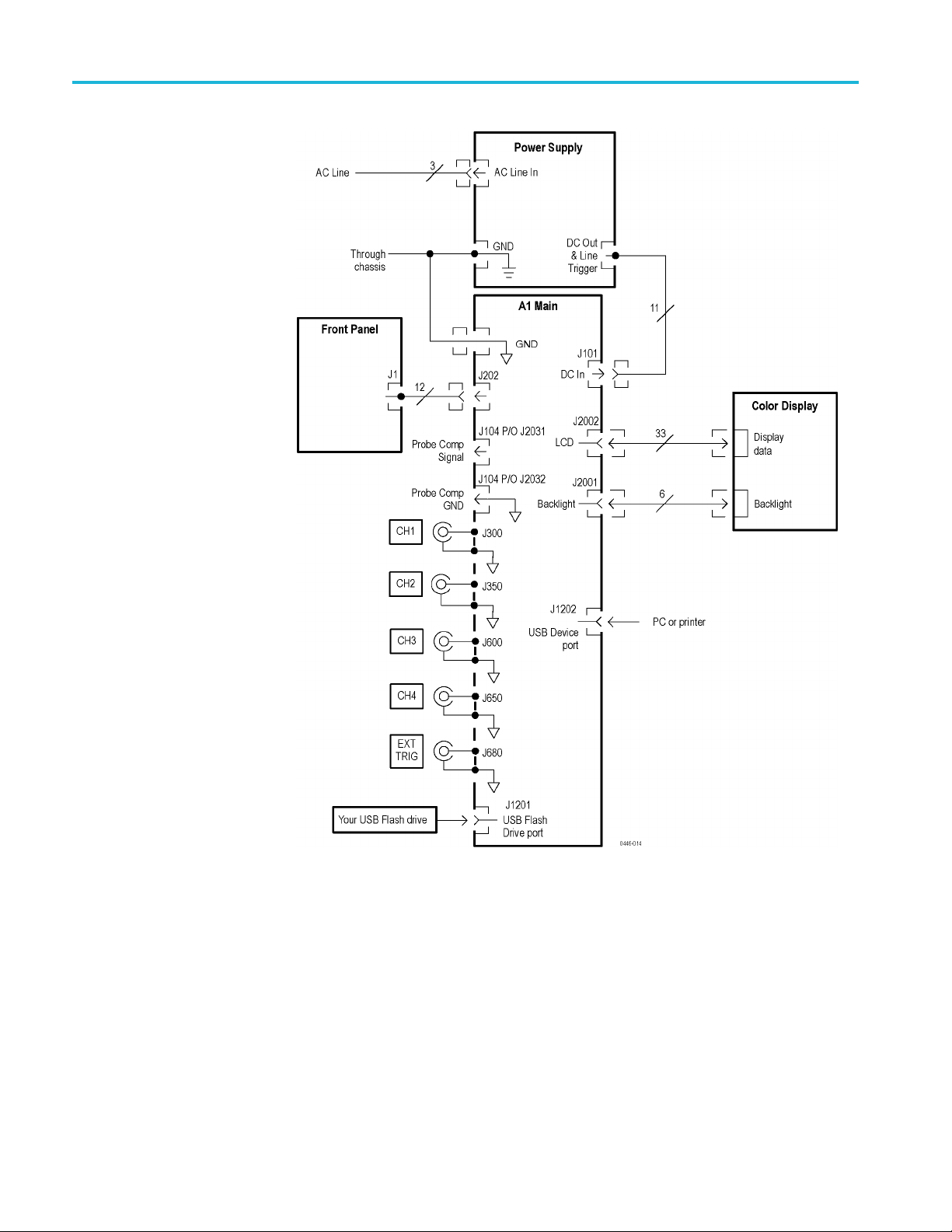
System Level Block Diagrams
Two high-level block diagram is provided. One shows 2-channel models and the
other show
on page 3-2.)
s 4-channel models. (See Figure 3-1 on page 3-1.) (See Figure 3-2
Figure 3-1: Module-level block diagram (2-channel)
TBS1000 Series Oscilloscope Service Manual 3–1
Page 40
Theory of Operation
Figure 3-2: Module-level block diagram (4-channel)
3–2 TBS1000 Series Oscilloscope Service Manual
Page 41

Main Board
Theory of Opera tion
The Main board is also called the acquisition board. The Main board of the
4-channel oscilloscope is essentially two 2-channel oscilloscopes tied together
throughacommonmicroprocessor,andsome special interconnects to support
combining the display and trigger systems. The focus of the Main board
discussion
noted as necessary.
is the 2-channel system, with differences for the 4-channel models
Acquisi
tion System
At a m inimu
digitizer/trigger system ASIC, a signal processing/display/system services FGPA,
RAM, flash PROM, a system microprocessor, USB controller, USB RAM, system
communication RAM, and special power supplies. For a 4-channel oscilloscope,
the attenuators are duplicated. Most of the other aspects of the circuitry remain
unchanged.
Signals from the channel 1 and channel 2 and other input connectors pass through
attenuators and an AC-coupling switch to the amplifier ASIC. The Ext Trig input
has an abbreviated version of this path, lacking some of the attenuator settings
and th
The amplifier ASIC contains buffers and variable gain amplifiers, as well as
s that provide 20 MHz bandwidth limiting. The task of the amplifier ASIC
filter
is to convert from a 1 MΩ single-ended environment in the front end to a much
lower impedance differential (and thus less noise-sensitive) environment for the
acquisition process. The amplifierASICassuresthattheinputsignalisamplified
to a level that will allow the fullest possible use of the digitizer.
The a cquisition ASIC contains samplers and peak detectors for each input
channel, a common amplifier, an A/D converter, and the trigger logic. The
digitized waveform samples are transferred to the processing and display FGPA.
n 4-channel systems, the two acquisition ASIC’s are interconnected so that a
I
trigger in one ASIC can cause a trigger on the other.
m, the Main board contains attenuators, an amplifier A S IC, a
e AC coupling switch.
he processor system adds the microprocessor and flash PROM to the processing
T
and display system. The processor system interprets the front-panel control
changes detec ted by the display ASIC, provides control parameters based on
user setting requests, computes waveform measurements, and manages the USB
interfaces via the dedicated USB controller. Saved setups, waveforms, and
calibration constants are stored in nonvolatile memory sections within the flash
PROM. The processor system shares DRAM with the display system.
TBS1000 Series Oscilloscope Service Manual 3–3
Page 42

Theory of Operation
Processing and Display
System
Input Signal Interface
Probe Compensation
The processing
system oscillator. Digitized acquisition samples are received by the display
ASIC and stored in DRAM. Once data are received by the display ASIC, various
corrections are applied, display rasterization is performed, and the waveform is
placed in a display buffer. At the same time, the waveform is read from the display
buffers and written to the LCD. Additional circuitry in the display ASIC supports
scanning th
clock, and performing various memory ma pping tasks required by all elementary
microprocessor based systems. In a 4–channel system, the two display ASICs are
interconnected so that one ASIC can provide display information for the second.
The processing and display system handles some of the computational tasks.
Other tasks are performed by the processor system. Since a ll array processing
is performed in the processing and display system, no computations can be
performed that involve data from two different channel sets. Thus, subtracting
channel 3 data from channel 2 is prohibited. Channel 1 and Channel 2 data may
be combined in all of the supported ways.
BNC connectors are mounted on the Main board for all signal inputs. The signal
inputs are compatible with the supplied TPP0101 and TPP0201 probes.
The Probe Comp and ground terminals are provided for probe adjustment.
and display system consists of the display ASIC, DRAM, and
e front panel, handling DRAM refresh, providing the processor
External Trigger
Main Board Power
Power Supply
The Ext Trig channel is processed on the chain containing the highest numbered
normal input channel.
To support various functions on the Main board, several secondary power sup
are generated. For the amplifier and acquisition ASICs, the Main board creates a
+2.5 V and -2.5 V supply. The +2.5 V supply is derived from the +3.3 V logic
supply. The -2.5 V supply is derived from the -4 V supply. One three-terminal
regulator provides +5 V for internal uses. A second three-terminal regulator
provides USB power to preclude USB faults from seriously disrupting operation
of the oscilloscope.
The main power supply module for these oscilloscopes is a wide input range
universal supply. It can provide about 25 W of power for the oscilloscope, while
allowing the input to run from about 90 V to 264 V. Input frequency ranges from
47 Hz to 440 Hz, which allows operation in virtually all countries in the world and
in several o ff-grid environments, such as power on military aircraft.
The secondary supplies from the power supply and the approximate current draws
are listed in a table with the associated connector pins on J101. (See Table 6-5.)
plies
3–4 TBS1000 Series Oscilloscope Service Manual
Page 43

Theory of Opera tion
Display Module
Front Panel
Two-Chan
Oscilloscopes
nel
The P2 connecto
For information on voltages used in the oscilloscope, refer to the Troubleshooting
section o f thi
The color di
The unit is patterned with 320 columns x 3 sub-columns by 240 rows and has
the associated drivers and back lig ht. The LED backlight outpu t is about 75 mA
at 15.5 V.
You can manipulate all of the switches, and position encoders on the Front-Panel
board of 2-channel oscilloscopes. Several LEDs are used to indicate when the
Multipurpose knob is active, when Autorange is active, and when a Save action
is in pr
your product.
An IC o
signals to the Main board. Two signals and a sense line are provided by the M ain
board to support the front panel. One of these lines resets the scan; a second line
clocks the scan to the next position; and the sense line receives the current state of
the selected switch or encoder position.
ogress. For more information on the LEDs, refer to the user manual for
n the Front-Panel board provides buffering and multiplexing of switch
r uses 4 positions and 3 wires, which are +6 V, +3.3 V, and GND.
smanual.
splay module is a standard passive liquid crystal display (LCD).
Four-Channel
Oscilloscopes
For the encoders, some amount of debouncing occurs inside the front-panel IC.
All key debouncing is handled in the display FPGA on the Main board.
The LEDs are controlled by latching the value of the Channel 1 - 2 front-panel
scan counter when the appropriate scan value is set.
The Front-Panel board of the 4-channel units is effectively two panels in parallel.
The left side of the board is largely handled by the display FPGA for channels
1 and 2. The right side of the board is handled by the channel 3 and 4 ASIC.
Separate front-panel ICs support these data paths.
TBS1000 Series Oscilloscope Service Manual 3–5
Page 44

Theory of Operation
3–6 TBS1000 Series Oscilloscope Service Manual
Page 45

Performance Verification
Page 46

Page 47

Performance Verifi cation
This chapter c ontains performance verification procedures for the specifications
marked with the check mark. The following equipment, or a suitable equivalent,
is required t
Required Equipment
o complete these procedures.
Table 4-1:
Descripti
DC Voltage
Leveled S
Time Mark
50Ω BNC Cable BNC male to BNC male, ≈ 1 m (36 in) long
50Ω BNC Cable BNC male to BNC male, ≈ 25 cm (10 in) long
50Ω Feedthrough Termination BNC male and female connectors
Dual Banana to BNC Adapter Banana plugs to BNC female
BNC T Adapter BNC male to dual BNC female connectors
Splitter, Power Frequency range: DC to 4 GHz.
pter (four required)
Ada
Adapter
Leads, 3 Black
ads, 2 Red
Le
Performance verification
on
Source
ine Wave Generator
Generator
Minimum re
17.5mVto7
50 kHz and
10 ms period, ±10 ppm accuracy
king: >2.0%
Trac
e N-to-female BNC
Mal
Fem
acking B anana Plug Patch Cord, ≈ 45 cm
St
(18 in) long
Stacking B anana Plug Patch Cord, ≈ 45 cm
(18 in) long
quirements
V, ±0.5% accuracy
200 MHz, ±3% amplitude accuracy
ale N-to-male BNC
Examples
Wavetek 91
System with Oscilloscope Calibration
Module (Option 250)
Fluke 550
Oscilloscope Calibration Option (Option
5500A-SC)
Tektronix part number 012-0482-XX
Tektronix part number 012-0208-XX
Tektronix part number 011-0049-XX
Tektronix part number 103-0090-XX
Tektronix part number 103-0030-XX
Tektronix part number 015-0565-XX
Tektronix part number 103-045-XX
Tektronix part number 103-0058-XX
mona #B-18-0
Po
Pomona #B-18-2
00 Universal Calibration
0A Multi-product Calibrator with
TBS1000 Series Oscilloscope Service Manual 4–1
Page 48

Performance Verification
Test Record
Table 4-2: Test record
Instrument Serial Number:
Temperature
:
Date of Calibration:
Certificate Number:
RH %:
Technician:
Instrument
performance test Minimum Incoming Outgoing Maximum
Channel 1
DC Gain Accuracy
5 mV/div
200 mV/div
2V/div
Channel 2
DC Gain Accuracy
5 mV/div
200 mV/div
2V/div
Channel 3
DC Gain Accuracy
1
5 mV/div
200 mV/div
2V/div
Channel 4
DC Gain Accuracy
1
5 mV/div
200 mV/div
2V/div
Channel 1 Bandwidth
Channel 2 Bandwidth
Channel 3 Bandwidth
Channel 4 Bandwidth
1
1
Sample Rate and Delay Time Accuracy
Channel 1 Edge Trigger Sensitivity Stable trigger
Channel 2 Edge Trigger Sensitivity Stable trigger
Channel 3 Edge Trigger Sensitivity
Channel 4 Edge Trigger Sensitivity
1
1
External Edge Trigger Sensitivity Stable trigger
Channel 1 Vertical Position Accuracy,
33.6 mV 36.4 mV
1.358 V 1.442 V
13.58 V 14.42 V
33.6 mV 36.4 mV
1.358 V 1.442 V
13.58 V 14.42 V
33.6 mV 36.4 mV
1.358 V 1.442 V
13.58 V 14.42 V
V
33.6 m
V
1.358
8V
13.5
V
2.12
2V
2.1
2V
2.1
12 V
2.
2divs
-
Stable trigger
Stable trigger
0
36.4 m
1.442
2V
14.4
2
—
2
—
2
—
2
—
2divs
+
3
—
3
—
3
—
3
—
3
—
—
V
V
Minimum margin
Channel 2 Vertical Position Accuracy,
0
—
Minimum margin
Channel 3 Vertical Position Accuracy
1
0
—
Minimum margin
Channel 4 Vertical Position Accuracy
1
0
—
Minimum margin
1
Channels 3 and 4 are only available on 4-channel oscilloscopes.
2
The bandw idth test does not have a high limit.
3
Thelimitsvarybymodel. Checkthe procedure for the correct limits.
4–2 TBS1000 Series Oscilloscope Service Manual
Page 49

Performance Verification
Performance V
Self Calibration
erification Procedures
Before beginning these procedures, two conditions must be met:
The oscilloscope must have been operating continuously for twenty minutes
within the operating temperature range specified in the Environmental
Performance table. (See Table 1-9.)
You must perform the Self Calibration operation described below. If the
ambient temperature changes by more than 5 °C, you must perform the Self
on operation again.
Some procedures use hazardous voltages. To prevent electrical
Self Test
Calibrati
The time required to complete the entire procedure is approximately one hour.
WAR N ING.
shock, always set voltage source outputs to 0 V before making or changing any
interconnections.
This internal procedure is automatically performed every time the oscilloscope
is powered on. No test equipment or hookups are required. Verify that no error
ges are displayed before continuing with this procedure.
messa
The self calibration routine lets you quickly optimize the oscilloscope s ignal path
for maximum measurement accuracy. You can run the routine at any time, but you
ld always run the routine if the ambient temperature changes by 5 °C or more.
shou
heck DC Gain Accuracy
C
1. Disconnect all probes and cables from the channel input connectors (channels
, and, for 4-channel models, channels 3 and 4).
1, 2
2. Push the Utility button and select the Do Self Cal option to start the routine.
e routine takes approximately o ne minute to complete.
Th
3. Verify that self calibration passed.
This test checks the DC gain accuracy of all input channels.
1. Set the DC voltage source output level to 0V.
2. Set up the oscilloscope using the following table:
Push menu button Select menu option Select setting
Default Setup
Channel 1
Acquire Average 16
Measure
——
Probe 1X
Source Channel under test
Type Mean
TBS1000 Series Oscilloscope Service Manual 4–3
Page 50

Performance Verification
3. Connect the osc
illoscope channel under test to the DC voltage source as
shown in the following figure:
4. For each vertical scale (volts/division) setting in the following table, perform
the following steps:
a. Set the DC voltage source output level to the positive voltage listed and
then record the mean measurement as V
pos
.
b. Reverse the polarity of the DC voltage source and record the mean
measurement as V
c. Calculate V
diff
=V
.
neg
pos-Vneg
and com pare V
to the accuracy limits in
diff
the following table:
Vertical Scale
(volts/div) setting
5 mV/div
200 mV/div
2V/div
DC voltage
source output levels Accuracy limits for V
+17.5 mV, -17.5 mV 33.6 mV to 36.4 mV
+700 mV, -700 mV 1.358 V to 1.442 V
+7.00 V, -7.00 V 13.58 V to 14.42 V
5. Set DC voltage source output level to 0V.
6. Disconnect the test setup.
7. Repeat steps 1 through 6 for all input channels.
diff
4–4 TBS1000 Series Oscilloscope Service Manual
Page 51

Performance Verification
Check Bandwidth
This test check
s the bandwidth of all input channels.
1. Set up the oscilloscope using the following table:
Push menu button Select menu option Select setting
Default Setup
Channel 1
Acquire Average 16
Trig Menu
Measure
2. Connect
the o scilloscope c hannel under test to the leveled sine wave generator
——
Probe 1X
Coupling
Source Channel under test
Type Pk-Pk
Noise Reject
as shown in the following figure:
3. Set t
he oscilloscope Vertical Scale (volts/division) to 500 mV/div.
4. Set the oscilloscope Ho rizontal Scale (seconds/division) to 10 ms/div.
5. Set the leveled sine wave generator frequency to 50 kHz.
6. Set the leveled sine wave generator output level s o the peak-to-peak
measurement is between 2.98 V and 3.02 V.
7. Set the leveled sine wave generator frequency to:
150 MHz if you are checking a TBS1154 or TBS1152
100 MHz if you are checking a TBS1104 or TBS1102
60 MHz if you are checking a TBS1064 or TBS1062
40 MHz if you are checking a TBS1042
25 MHz if you are checking a TBS1022
8. Set the oscilloscope Horizontal Scale (seconds/division) to 10 ns/div.
9. Check that the peak-to-peak measu rement is ≥ 2.12 V.
TBS1000 Series Oscilloscope Service Manual 4–5
Page 52

Performance Verification
Check Sample R
ate
Accuracy and Delay Time
Accuracy
10. Disconnect the
test setup.
11. Repeat steps 1 through 10 for all input channels.
This test checks the time base accuracy.
1. Set up the oscilloscope using the following table:
Push menu bu
Default Se
Channel 1
tup
tton
Select menu
——
Probe 1X
option
Select sett
ing
2. Connect the oscilloscope to the time mark generator as shown in the following
figure:
3. Set the time m ark generator period to 10 ms.
4. Set the oscilloscope Vertical Scale (volts/division) to 500 mV/div.
5. Set the oscilloscope M ain Horizontal Scale (seconds/division) to 1ms/div.
6. Push Set To 50%.
7. Use the Ve rt ical Po s itio n control to center the test signal on screen.
8. Us
etheHorizontal Position control to set the position to 10.00 ms.
9. Set the oscilloscope Horizontal Scale (seconds/division) to 250 ns/div.
4–6 TBS1000 Series Oscilloscope Service Manual
Page 53

Performance Verification
10. Check that the r
ising edge of the marker crosses the center horizontal graticule
line within ±2 divisions of the vertical center graticule line, as shown in the
following figure:
NOTE. On
e division of displacement from graticule center corresponds to a
25 ppm time base error.
Check
Edge Trigger
Sensitivity
11. Disconnect the test setup.
This test checks the edge trigger sensitivity for all input channels.
1. Set up the oscilloscope using the following table:
menu button
Push
ault Setup
Def
nnel 1
Cha
Trig Menu Mode Normal
Acquire
Measure
ct menu option
Sele
——
Probe 1X
Sample
Source Channel under test
Type Pk-Pk
Sele
—
ct setting
TBS1000 Series Oscilloscope Service Manual 4–7
Page 54

Performance Verification
2. Connect the osc
illoscope channel under test to the leveled sine wave generator
as shown in the following figure:
3. Set the osc
illoscope Vertical Scale (volts/division) to 500 mV/div.
4. Set the oscilloscope Horizontal Scale (seconds/division) to 25 ns/div.
5. Set the leveled sine wave generator frequency to 10 MHz.
6. Set the leveled sine wave g enerator output level to approximately 500 mV
so that the measured amplitude is approximately 500 mV.(Themeasured
amplitude can fluctuate around 500 mV.)
p-p
7. Push Set To 50%. Adjust Trigger Level as necessary and then check that
triggering is stable.
8. Set the leveled sine wave generator frequency to:
100 MHz if you are checking a TBS1154, TBS1152, TBS1104, or a
TBS1102
60 MHz if you are checking a TBS1064 or TBS1062
40 MHz if you are checking a TBS1042
25 MHz if you are checking a TBS1022
t the oscilloscope Horizontal Scale (seconds/division) to 5ns/div.
9. Se
10. Set the leveled sine wave generator output level to approximately 750 mV
so that the measured amplitude is approximately 750 mV.(Themeasured
p-p
amplitude can fluctuate around 750 mV.)
ush Set To 50%. Adjust Trigger Level as necessary and then check tha t
11.P
triggering is stable.
12. For the TBS1154 and TBS1152 models, set the frequency to 150 MHz, and
increase the amplitude to 1 V
. Verify stable triggering.
p-p
13. Set the oscilloscope Horizontal Scale (seconds/division) to 2.5 ns/div.
14. Change the oscilloscope setup using the following table:
4–8 TBS1000 Series Oscilloscope Service Manual
Page 55

Performance Verification
Push menu button Select menu option Select setting
Trig Menu
Slope
Falling
15. Push Set To 50%. Adjust Trigger Level as necessary and then check that
triggering is stable.
16. Disconnect the test setup.
17. Repeat steps 1 through 16 for all input channels.
Check External Edge
Trigger Sensitivity
This test checks the edge trigger sensitivity for the external trigger.
1. Set up the oscilloscope using the following table:
Push menu button Select menu option Select setting
Default Setup
Channel 1
Trig Menu
Acquire
Measure
——
Probe 1X
Source
Mode Normal
Sample
Source CH1
Type Pk-Pk
Ext
—
2. Connect the oscilloscope to the leveled sine w ave generator as shown in the
following figure, using channel 1 and Ext Trig.
3. Set the oscilloscope Vertical Scale (volts/division) to 100 mV/div.
4. Set the oscilloscope Horizontal Scale (seconds/division) to 25 ns/div.
5. Set the leveled sine wave generator frequency to 10 MHz.
6. Set the sine wave generator output level to approximately 300 mV
power splitter. This is about 200 mV
on channel 1 of the oscilloscope.
p-p
into the
p-p
TBS1000 Series Oscilloscope Service Manual 4–9
Page 56

Performance Verification
The Ext Trig inp
ut will also be receiving approximately 200 mV
deviations from the nominal 200 mV
7. Set the levele
d sine wave generator frequency to:
oscilloscope display are acceptable.
p-p
. Small
p-p
150 Mhz if you are checking a TBS1154 or a TBS1152
100 MHz if you are checking a TBS1104 or a TBS1102
60 MHz if you are checking a TBS1064 or a TBS1062
40 MHz if you are checking a TBS1042
25 MHz if you are checking a TBS1022
8. Set the os
cilloscope Horizontal Scale (seconds/division) to 5ns/div.
9. Push Set To 50%. Adjust Trigger Level as necessary and then check that
ing is stable.
trigger
10. Set the oscilloscope Horizontal Scale (seconds/division) to 2.5 ns/div.
11. Push Set To 50%. Adjust Trigger Level as necessary and then check that
triggering is stable.
12. Change the oscilloscope setup using the following table:
Check Vertical Position
Accuracy
Push m enu button Select menu option Select setting
Trig
Menu
Slope
Fall
ing
13. Push Set To 50% . Adjust Trigger Level as necessary and then check that
triggering is stable.
14. Disconnect the test setup.
The results of this test and the DC Gain Accuracy test together define the DC
Measurement Accuracy of the oscilloscope. The DC Measurement Accuracy
specification encompasses two different ranges of operation over two different
attenuator settings.
DC Gain Accuracy: Identifies errors, mostly from the A/D converter,
when the vertical position (known as offset in these oscilloscopes) is set to
0 divisions (or a grounded input will show screen center)
Vertical Position Accuracy: Identifies errors, mostly from the position control,
made when the vertical position is set to a non-zero value
The two attenuator settings operate identically, so verification of the attenuation
range from -1.8 V to 1.8 V also verifies the attenuation range of -45 V to 45 V.
4–10 TBS1000 Series Oscilloscope Service Manual
Page 57

Performance Verification
1. Set up the oscil
loscope as shown in the following table:
Push menu button Select menu option Select setting
Default Setup
Channels 1, 2, 32, 4
Channels 1, 2, 32, 4
Trig Menu
2
2
——
Probe 1X
Volts/Div 50 mV/div
1
Source
Ext
Mode Auto
Acquire
Measure
Sample
Source Channel under test
—
Type Mean
1
The test operates without a trigger. To maintain uniformity and to avoid false triggering on noise, the Ext trigger is
the recomme nded source.
2
Available only on a 4-channel oscilloscope.
2. Make a spreadsheet approximately as shown in the example in Appendix A.
You only need to enter the values for column A and the equations. The values
incolumnsB,C,D,E,F,andGareexamplesofthemeasuredorcalculated
values.
The P DF version of the service manual (which you can download from
www.tektronix.com/manuals), includes an empty spreadsheet for your
convenience. To access and save the test spreadsheet, see the instructions
in Appendix A: Exam ple of a Vertical Position Accuracy Test Spreadsheet
on page A-1.
3. Connect the oscilloscope, power supply, and voltmeter as shown in the
following figure:
TBS1000 Series Oscilloscope Service Manual 4–11
Page 58

Performance Verification
4. Set the power su
Test Voltage.
5. Adjust the ver
center of the screen.
6. Enter the vo
in the appropriate columns, B and C.
7. Repeat step
8. Swap the connections to the positive terminal of the power supply with those
at the nega
pply to the 1.8 V value shown in column A, the Approximate
tical position knob for the DC line to position the line in the
ltage on the voltmeter and on the oscilloscope into the spreadsheet
s 4 through 6 for the values of 1.76 V through 0 V.
tive terminal as shown in the following figure:
9. Repeat steps 4 through 6 for the values of -0.04 V through -1.8 V.
10. Enter the Minimum Margin number (cell I16) for the channel tested in the
test record.
11. Repeat steps 1 through 10 for all input channels.
4–12 TBS1000 Series Oscilloscope Service Manual
Page 59

Performance Verification
Data verificati
columns D, E, and F. Verify that no error values (the blue line in the center) go
above the yellow line (upper line), or below the purple line (lower line). For
calculations involved in this example, refer to the data in the previous table (see
step 1).
on. To verify data, set the spreadsheet to present a line graph of
Figure 4-1: Example of a line graph for the Vertical Position Accuracy test
TBS1000 Series Oscilloscope Service Manual 4–13
Page 60

Performance Verification
4–14 TBS1000 Series Oscilloscope Service Manual
Page 61

Adjustment Procedures
Page 62

Page 63

Adjustment Procedures
This section contains adjustment procedures for the TBS1000 series oscilloscopes.
Only qualified personnel should perform service procedures. Read the Service
Safety Summary and the General Safety Summary at the b eginning of this
manual before performing any service procedures. Refer to the user manual for
information about using these oscilloscopes.
NOTE. The voltage references inside the oscilloscopes are very stable over time
and do not r
unless the oscilloscope does not meet specifications. Refer to the Performance
Ver ification section to check the oscilloscope performance to specifications.
equire routine updates. Do not perform any procedure in this section
Require
dEquipment
The equipment described in the following table, or a suitable equivalent, is
required to complete these p rocedures. (See Table 5-1.)
Table 5
Descri
DC Vol
Level
50 Ω BNC Cable BNC male to BNC male, ≈ 1 m (36 in) long
50 Ω BNC Cable (seven) BNC male to BNC male, ≈ 25 cm (10 in) long
50 Ω Feedthrough Termination BNC m ale and female connectors
Dual Banana to BNC Adapter Banana plugs to BNC female
BNC T (three) One male and two female BNC connectors
-1: Required equipment
ption
tage Source
ed Sinewave Generator
m requirements s
Minimu
o 20 V, ± 0.1% accuracy
-20 V t
nd 200 MHz, ±0.6% amplitude accuracy
5kHza
Adjustment Procedure
e
Exampl
ek 9100 Universal Calibration
Wavet
System with Oscilloscope Calibration
Module (Option 250)
e 5500A Multi-product Calibrator with
Fluk
Oscilloscope Calibration Option (Option
5500A-SC)
Tektronix part number 012-0482-XX
Tektronix part number 012-0208-XX
Tektronix part number 011-0049-XX
Tektronix part number 103-0090-XX
Tektronix part number 103-0030-XX
The adjustment procedure consists of 70 steps for the 2-channel oscilloscope and
106 steps for the 4-channel model. Each step requires an external voltage source
for new calibration constants.
Before performing the adjustment procedure, warm up the oscilloscope for at least
ten minutes in an ambient tempe rature between 20 °C and 30 °C. Adjustments
performed before warm up or outside this temperature range may result in poor
performance.
TBS1000 Series Oscilloscope Service Manual 5–1
Page 64

Adjustment Procedures
Enable the Service Menu
If all steps in t
displayed and the new calibration constants take effect. If any step fails, the
procedure is aborted and the current calibration is not affected. You can choose
to abort the procedure at any step, without affecting the current calibration, by
selecting FCAL ABORT.
NOTE. While performing the adjustment procedure, keep in mind that some of the
steps take a
Equipment setups are shown i n the following figure. (See Figure 5-1 on page 5-3.)
Signal re
on page 5-5.)
Before performing the adjustment procedure, enable the Service menu as follows:
1. Power on the oscilloscope.
2. Push the front-panel Measure button to access the Measure menu.
3. Push the top option b utton to access the Measure 1 menu.
4. Push and hold the front-panel Single button.
he procedure are completed successfully, a "Pass" message is
significant amount of time (up to 5 minutes) to complete.
quirements for each step are shown in the following table. (See Table 5-2
5. Push
6. Wait at least two seconds.
7. Release the Single button.
8. Release the AutoSet button. A message appea rs in the lower left corner of the
9. Push the front-panel Utility button. The last item in the Utility menu is now
At completion of the Adjustment procedure, disable the "Service" menu through
the Utility front panel button, th e "Service" option button, and the "Service"
Mode Off" option button.
and hold the front-panel AutoSet button.
screen stating "Service mode ON."
"Service."
5–2 TBS1000 Series Oscilloscope Service Manual
Page 65

Adjustment Procedures
Figure 5-1: Adjustment setups
TBS1000 Series Oscilloscope Service Manual 5–3
Page 66

Adjustment Procedures
Adjustment Procedure
Use this proced
uretoloadnewcalibrationconstants.
1. Enable the Service menu. (Se e page 5-2, Enable the Service Menu.)
2. Push the Service option button.
3. Push the Factory Cal option button.
4. Push the Warmup Time r option button.
5. Push the Start Timer option button to allow a 10-minute warm up. After
10 minutes, the oscilloscope displays a large black or green cross.
6. Press the front-panel Utility button and push the Service option button.
7. Push the Factory Cal option button.
8. Push the F
CAL INIT option button to initiate the factory calibration routine.
You are now in step 1 of the procedure.
9. As indic
ated by step 1, connect a 0.0 V
source to the channel inputs. (See
DC
Table 5-2.)
10. Press F
CAL STEP to load the calibration constant for step 1.
11. Follow the screen prompts and the Adjustment setup table for the remainder
routine, applying the proper signal for each step. (See Table 5-2.)
of the
NOTE. During some steps, the oscilloscope may appear to be idle for several
minutes while it is processing inform atio n internally. You must wait for the screen
prompt to continue.
If any step in the procedure fails, the procedure terminates. Failure will result
if an incorrect signal source is connected. If this happens, you must start the
procedure over from the beginning.
If the procedure completes successfully, a "Pass" message is displayed and the
new adjustment takes effect.
12. Compensate the signal path by performing the self-calibration routine.
13. Disconnect all probes and cables from the channel input connectors.
14. Press the Utility button and select Do Self Cal to con firm that you are ready
to proceed.
15. Disable the Service menu option by pushing the Utility front-panel button and
the Service and ServiceModeOffoption buttons.
5–4 TBS1000 Series Oscilloscope Service Manual
Page 67

Adjustment Procedures
Table 5-2: Adju
Input Setup diagram Step number Signal Signal source setting
Ch 1 through
Ch x
Ext Trig
stment steps
DC voltage 1
DC voltage 2
1
2
3
4
5
6
7
8
9
10
11
12
13
14
15
16
17
18
1
2
21
22
23
24
25
26
27
28
29
30
31
32
33
34
DC Voltage 1
DC Voltage 1
DC Voltage 1
DC Voltage 1
DC Voltage 1
DC Voltage 1
DC Voltage 1
DC Voltage 1
DC Voltage 1
DC Voltage 1
DC Voltage 1
DC Voltage 1
DC Voltage 1
DC Voltage 1
DC Voltage 1
DC Voltage 1
DC Voltage 1
DC Voltage 1
9
0
DC Voltage 1
DC Voltage 1
DC Voltage 1
DC Voltage 1
DC Voltage 1
DC Voltage 1
DC Voltage 1
DC Voltage 1
DC Voltage 1
DC Voltage 1
DC Voltage 1
DC Voltage 1
DC Voltage 2
DC Voltage 2
DC Voltage 2
DC Voltage 2
0.0 V
-20.0 V
-2.0 V
-1.6 V
-1.2 V
-0.8 V
-0.4 V
-0.32 V
-0.2 V
-0.16 V
-0.08 V
-0.04
3V
-0.0
2V
-0.0
015 V
-0.
15 V
0.0
02 V
0.
03 V
0.
.04 V
0
.08 V
0
0.16 V
0.2 V
0.32 V
0.4 V
0.8 V
1.2 V
1.6 V
2.0 V
20.0 V
0.0 V
-5.0 V
-1.0 V
1.0 V
5.0 V
V
TBS1000 Series Oscilloscope Service Manual 5–5
Page 68

Adjustment Procedures
Table 5-2: Adjustment steps (cont.)
Input Setup diagra m Step number Signal Signal source setting
Ch 1
Sinewave
generator
35
36
37
38
39
40
41
42
43
44
45
46
47
48
49
50
51
52
Edge 53
Sinewave Generator, 50 Ω
Sinewave Generator, 50 Ω
Sinewave Generator, 50 Ω
Sinewave Generator, 50 Ω
Sinewave Generator, 50 Ω
Sinewave Generator, 50 Ω
Sinewave Generator, 50 Ω
Sinewave Generator, 50 Ω
Sinewave Generator, 50 Ω
Sinewave Generator, 50 Ω
Sinewave Generator, 50 Ω
Sinewave Generator, 50 Ω
Sinewave Generator, 50 Ω
Sinewave Generator, 50 Ω
Sinewave Generator, 50 Ω
Sinewave Generator, 50 Ω
Sinewave Generator, 50 Ω
Sinewave Generator, 50 Ω
Edge, 50 Ω.
5kHz,1V
1 MHz, 100 mV
1MHz,1V
50 kHz, 1 V
20 MHz, 1 V
BWL, 25 mV
BWL, 50 mV
BWL, 100 mV
BWL, 250 mV
BWL, 500 mV
BWL, 1 V
5kHz,2.5V
1MHz,2.5V
50 kHz, 2.5 V
20 MHz, 2.5 V
BWL, 2.5 V
BWL, 5 V
BWL, 1.6 V
p-p
p-p
p-p
p-p
p-p
p-p
p-p
p-p
p-p
p-p
p-p
p-p
p-p
p-p
p-p
p-p
p-p
p-p
1 k Hz, 0 to -800 mV
5–6 TBS1000 Series Oscilloscope Service Manual
Page 69

Adjustment Procedures
Table 5-2: Adjustment steps (cont.)
Input Setup diagram Step number Signal Signal source setting
Ch 2 Sinewave
generator
Ch 3
(4-Ch models
Sinewave
generator
only)
Edge 89
54
55
56
57
58
59
60
61
62
63
64
65
66
67
68
69
70
71
72
73
74
75
76
77
78
79
80
81
82
83
84
85
86
87
88
Sinewave Generator, 50 Ω
Sinewave Generator, 50 Ω
Sinewave Generator, 50 Ω
Sinewave Generator, 50 Ω
Sinewave Generator, 50 Ω
Sinewave Generator, 50 Ω
Sinewave Generator, 50 Ω
Sinewave Generator, 50 Ω
Sinewave Generator, 50 Ω
Sinewave Generator, 50 Ω
Sinewave Generator, 50 Ω
Sinewave Generator, 50 Ω
Sinewave Generator, 50 Ω
Sinewave Generator, 50 Ω
Sinewave Generator, 50 Ω
Sinewave Generator, 50 Ω
Sinewave Generator, 50 Ω
Sinewave Generator, 50 Ω
Sinewave Generator, 50 Ω
Sinewave Generator, 50 Ω
Sinewave Generator, 50 Ω
Sinewave Generator, 50 Ω
Sinewave Generator, 50 Ω
Sinewave Generator, 50 Ω
Sinewave Generator, 50 Ω
Sinewave Generator, 50 Ω
Sinewave Generator, 50 Ω
Sinewave Generator, 50 Ω
Sinewave Generator, 50 Ω
Sinewave Generator, 50 Ω
Sinewave Generator, 50 Ω
Sinewave Generator, 50 Ω
Sinewave Generator, 50 Ω
Sinewave Generator, 50 Ω
Sinewave Generator, 50 Ω
Edge, 50 Ω.
5kHz,1V
1 MHz, 100 mV
1MHz,1V
50 kHz, 1 V
20 MHz, 1 V
BWL, 25 mV
BWL, 50 mV
BWL, 100 mV
BWL, 250 mV
BWL, 500 mV
BWL, 1 V
5kHz,2.5V
1MHz,2.5V
50 kHz, 2.5 V
20 MHz, 2.5 V
BWL, 2.5 V
BWL, 5 V
5kHz,1V
1 MHz, 100 mV
1MHz,1V
50 kHz, 1 V
20 MHz, 1 V
BWL, 25 mV
BWL, 50 mV
BWL, 100 mV
BWL, 250 mV
BWL, 500 mV
BWL, 1 V
5kHz,2.5V
1MHz,2.5V
50 kHz, 2.5 V
20 MHz, 2.5 V
BWL, 2.5 V
BWL, 5 V
BWL, 1.6 V
p-p
p-p
p-p
p-p
p-p
p-p
p-p
p-p
p-p
p-p
p-p
p-p
p-p
p-p
p-p
p-p
p-p
p-p
p-p
p-p
p-p
p-p
p-p
p-p
p-p
p-p
p-p
p-p
p-p
p-p
p-p
p-p
p-p
p-p
p-p
1 kHz, 0 to -800 mV
TBS1000 Series Oscilloscope Service Manual 5–7
Page 70

Adjustment Procedures
Table 5-2: Adjustment steps (cont.)
Ch 4
(4-ch models
only)
Sinewave
generator
90
91
92
93
94
95
96
97
98
99
100
101
102
103
104
105
106
Sinewave Generator, 50 Ω
Sinewave Generator, 50 Ω
Sinewave Generator, 50 Ω
Sinewave Generator, 50 Ω
Sinewave Generator, 50 Ω
Sinewave Generator, 50 Ω
Sinewave Generator, 50 Ω
Sinewave Generator, 50 Ω
Sinewave Generator, 50 Ω
Sinewave Generator, 50 Ω
Sinewave Generator, 50 Ω
Sinewave Generator, 50 Ω
Sinewave Generator, 50 Ω
Sinewave Generator, 50 Ω
Sinewave Generator, 50 Ω
Sinewave Generator, 50 Ω
Sinewave Generator, 50 Ω
5kHz,1V
p-p
1 MHz, 100 mV
1MHz,1V
50 kHz, 1 V
20 MHz, 1 V
BWL, 25 mV
BWL, 50 mV
p-p
p-p
p-p
p-p
p-p
BWL, 100 mV
BWL, 250 mV
BWL, 500 mV
BWL, 1 V
5kHz,2.5V
1MHz,2.5V
p-p
p-p
p-p
50 kHz, 2.5 V
20 MHz, 2.5 V
BWL, 2.5 V
BWL, 5 V
p-p
p-p
p-p
p-p
p-p
p-p
p-p
p-p
NOTE. BWL=full bandwidth for the TBS1022, 1042, 1062, 1102, and 1104.
BWL=180 Mhz for the TBS1152 and TBS1154
5–8 TBS1000 Series Oscilloscope Service Manual
Page 71

Maintenance
Preventing ESD
This chapter contains the informationneededtodoperiodicandcorrective
maintenance on the oscilloscope, as well as repackaging instructions to use if you
need to return the oscilloscope to Tektronix for service.
Before servicing this product, read the Safety Summary and Introduction at the
front of the manual and the electrostatic discharge (ESD) information below.
CAUTION. Static discharge can damage any semiconductor component in this
oscilloscope.
When performing any service which requires internal access to the oscilloscope,
adhere to the following precautions. T hese precautions help you avoid damaging
internal modules and their components due to electrostatic discharge (ESD):
Minimize handling of static-sensitive modules.
Transport and store static-sensitive modules in their static protected containers
or on a metal rail. Label any package that contains static-sensitive modules.
Inspection and Cleaning
Inspection and cleaning are done as preventive maintenance. Preventive
maintenance, when done regularly, can prevent oscilloscope malfunction and
enhance its reliability.
Preventive maintenance consists of visually inspecting and cleaning the
osc
maintenance depends on the severity of the environment in which you use the
oscilloscope. A good time to perform preventive maintenance is just before
adjustment of the oscilloscope.
Discharge the static voltage from your body by w earing a grounded antistatic
wrist strap while handling these modules.
Service static-sensitive modules only at static-free workstations. Do not allow
anything capable of g enerating or holding a static charge on the workstation
surface.
Handle circuit boards by the edges when possible.
Do not slide the modules over any surface.
Avoid handling modules in areas th
capable of generating a static charge.
illoscope, and using general care when operating it. How often you do
at have a floor or work-surface covering
TBS1000 Series Oscilloscope Service Manual 6–1
Page 72

Maintenance
General Care
Interior Cleaning
For best perfor
Protect the oscilloscope from adverse weather conditions. The oscilloscope is
not waterproo
Do not store or leave the oscilloscope where the liquid crystal display (LCD)
is exposed t
The front and rear cases help keep dust out of the oscilloscope and must be in
place durin
To avoid damage to the oscilloscope or probes, do not expose them to any
sprays, li
Use a dry, low-velocity stream of air to clean the interior of the chassis. Use a
soft-bristle, non-static-producing brush for cleaning around components. If you
must use
and rinse with deionized water.
WARNING. To avoid injury, power off the instrument and disconnect it from line
voltage before performing any procedure that follows.
mance, follow these recommendations:
f.
o direct sunlight or high humidity for long periods of time.
g normal operation.
quids, or solvents.
a liquid for minor interior cleaning, use a 75% isopropyl alcohol solution
Exterior Cleaning
ION. Avoid the use of chemical cleaning agents, which might damage the
CAUT
plastics used in this oscilloscope. Use only deionized water when cleaning the
menu buttons or front-panel buttons. Use a 75% isopropyl alcohol solution as a
cleaner and rinse with deionized water. Before using any other type of cleaner,
consult your Tektronix Service Center or representative.
Clean the exterior surfaces of the chassis with a dry lint-free cloth or a soft-bristle
brush. If any dirt remains, use a cloth or swab dipped in a 75% isopropyl alcohol
solution. Use a swab to clean narrow spaces around controls and connectors.
o not use abrasive compounds on any part of the chassis that may damage the
D
chassis.
CAUTION. To prevent getting moisture inside the oscilloscope during external
cleaning, use only enough liquid to dampen the cloth or applicator.
Clean the On/Standby switch using a dampened cleaning towel. Do not spray or
wet the switch directly.
6–2 TBS1000 Series Oscilloscope Service Manual
Page 73

Maintenance
If the display i
s very dirty, moisten the wipe with distilled water or a 75%
isopropyl alcohol solution and gently rub the display surface. Avoid using excess
force or you may damage the plastic display surface.
Exterior Inspection
Inspect the o
utside of the oscilloscope for damage, wear, and missing part. (See
Table 6-1.) Immediately repair defects that could cause personal injury or lead
to further damage to the oscilloscope.
Table 6-1: External inspection checklist
Item Inspect for Repair action
Front and rear case
Front-panel knobs Missing, damaged, or loose knobs
Connectors
Carrying handle, and cabinet feet Correct operation Repair or replace defective module
Accessories
Cracks, scratches, deformations, damaged
hardware
Broken shells, cracked insulation, and
deformed contacts. Dirt in connectors
Missing items or parts of items, bent pins,
broken or frayed cables, and damaged
connectors
Repair or replace defective module
Repair or replace missing or defective knobs
Repair or replace defective modules. Clear
or wash out dirt.
Repair or replace damaged or missing
items, frayed cables, and defective modules
Interior Inspection
To access the inside of the oscilloscope for inspection and cleaning, refer to the
val Procedures in this section.
Remo
Inspect the internal portions of the oscilloscope for dam age and wear. (See
le 6-2.) Repair any defects immediately.
Tab
If any circuit board is repaired or replaced, check the table to see if it is necessary
adjust the oscilloscope. (See Table 6-2.)
to
CAUTION. To prevent damage from electrical arcing, make sure that circuit
boards and components are dry before applying power to the oscilloscope.
TBS1000 Series Oscilloscope Service Manual 6–3
Page 74

Maintenance
Table 6-2: Inte
Item Inspect for Repair action
Circuit boards
Resistors Burned, cracked, broken, blistered
Solder conn
Capacitor
Wiring and
Chassis Dents, deformations, and damaged
Cleaning Procedure,
rnal inspection checklist
ections
s
cables
Interior
Loose, broken
connections. Burned circuit boards.
Burned, broken, or cracked circuit-run
plating.
condition.
Cold solder
Damaged or
solder on leads or terminals.
Loose plug
or frayed wiring.
hardware.
, or corroded solder
or rosin joints.
leaking cases. Corroded
s or connectors. Burned, broken,
Remove and rep
Remove and replace damaged circuit board.
Resolder joint and clean with isopropyl
alcohol.
Remove and replace damaged circuit board.
Firmly sea
modules with defective wires o r cables.
Straighten, repair, or replace defective
hardware.
t connectors. Repair or replace
To clean the oscilloscope interior, perform the following steps:
1. Blow off dust with dry, low-pressure, deionized air (approximately 9 psi).
2. Remove any remaining dust with a lint-free c loth dampened in isopropyl
alcohol (75% solution) and then wipe w ith a lint-free cloth dampened with
warm deionized water. A cotton-tipped applicator is useful for cleaning in
narrow spaces and on circuit boards.
lace damaged circuit board.
STOP. If, after performing steps 1 and 2, a module is clean on inspection, skip
steps 3, 4, and 5. Proceed with step 6.
6–4 TBS1000 Series Oscilloscope Service Manual
Page 75

Maintenance
3. Ifsteps1and2d
oscilloscope except the Display Module and F ront Panel Module may be
spray washed using a solution of 75% isopropyl alcohol.
During cleaning of the Acquisition board (Main board), make sure that
no residue is left in the attenuators. Debris or residue can c ause several
problems with signal fidelity that cannot be corrected by calibration.
When handling the board, avoid handling the attenuators since skin oils
may cause problem s.
Extensive cleaning of the Display Module is difficult because water must
not be trapped between the display shield and the display. The polarizers
integrat
display shield and display must be replaced as an assembly if significant
moisture or debris become trapped inside. Cotton tipped applicators and
lint-free rags moistened in isopropyl alcohol and/or deionized water offer
the best cleaning with the least opportunity for damage to the assembly.
The Front-Panel module can be damaged by deposition of film or debris
inside the knob encoders. To avoid this, be careful not to drip liquid or
blow debris into the encoders.
4. Spray wash dirty parts with the 75% isopropyl alcohol solution and wait
60 seconds for the majority of the alcohol to evaporate.
o not remove all the dust or dirt, all modules in the
ed into the d isplay degrade with long-term exposure to water. The
5. Use hot (49 °C to 60 °C / 120 °F to 140 °F) deionized water to thoroughly
rinse the parts.
6. Dry all parts with low-pressure, deionized air.
7. Dry all com p onents and assemblies in an oven or drying compartment using
low-temperature (52 °C to 66 °C / 125 °F to 150 °F) circulating air.
brication. Periodic lubrication is not required for the oscilloscope.
Lu
TBS1000 Series Oscilloscope Service Manual 6–5
Page 76

Maintenance
Removal and Installation Procedures
WARNING. Only qualified personnel should perform service procedures. Before
doing this or a
Summary and Service Safety Summary found at the beginning of this manual. To
prevent damage to electrical components, refer Preventing ESD. (See page 6-1,
Preventing ESD.)
Always disconnect the power cord before disassembling any part of the
oscilloscope.
Refer to the module locator drawings to find the modules that you want to remove
or install. (See Figure 6-1 on page 6-7.) (See Figure 6-2 o n page 6-7.)
Refer to the Inspection and Cleaning procedure if you are disassembling the
instrument for c leaning. (See page 6-1, Inspection and Cleaning.)
Refer to the Replaceable Parts List for a list of all replaceable modules and their
part numbers.
ny other procedure in this manual, read the General Safety
Summary of Procedures
Refer to the Exploded View Diagrams for each procedure, as indicated in the table.
Complete disassembly is best achieved by following the procedures in the order
n in the following table:
give
Procedure Begins on page
Feet
Rear
p Feet
Fli
nt-Panel Knobs
Fro
Rear Case (See page 6-10, Rear Case.)
ont Feet
Fr
Power Supply Module (See page 6-12, Power Supply M odule.)
nternal Assembly
I
Front-Panel Cable (See page 6-15, Front-Panel Cable.)
Main Board Module
Display Module
Front-Panel Module
Keypad
(See page 6-8, Rear Feet.)
(See page 6-9, Flip Feet.)
(See page 6-9, Front-Panel Knobs.)
(See page 6-11, Front Feet.)
(See page 6-13, Internal Assembly.)
(See page 6-16, Main Board Module (without the Display
Adapter Module).)
(See page 6-19, Display Module.)
(See page 6-20, Front-Panel Module.)
(See page 6-21, Keypad.)
6–6 TBS1000 Series Oscilloscope Service Manual
Page 77
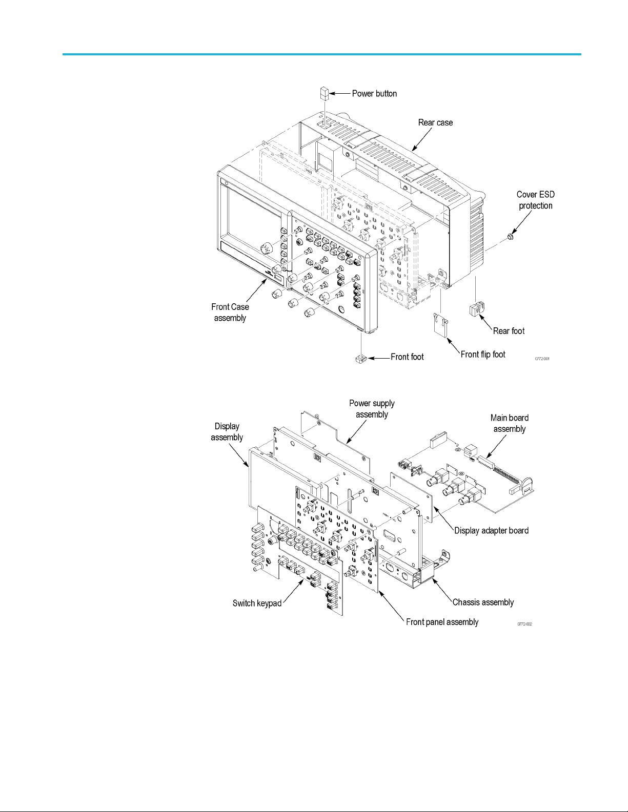
Maintenance
Figure 6-1: Locator for trim and cabinet removal (2-channel model shown)
Figure 6-2: Locator for internal modules (2-channel model shown)
TBS1000 Series Oscilloscope Service Manual 6–7
Page 78

Maintenance
Required Tools
Rear Fe et
Use the followi
Torque-limiting screwdriver, long shank, 12 in-lb (1.3 N·m) range with Torx®
T-15 tip; if yo
bit must be a long bit, at least 5 cm (2 in) overall length
Torque-lim
5/8 inch deep socket with wide center hole (S·K Hand Tool Corp., S-K
#40820, or e
Torque wrench to 40 in-lb (4.5 N·m)
Screwdriver with 1/4 inch flat blade
Pliers (all-purpose and needle-nose)
Sharp knife (X-ACTO®knife or equivalent)
3M Electrical Tape 92 with 1-mil polyimide Kapton backing, temperature
rated 180 °C, UL510 Flame Retarded
You wi l
Refer to the exploded view diagram for the back case and trim. (See page 8-10.)
l need a flat-blade screwdriver to remove the rear feet.
ng tools to remove and replace all modules in the oscilloscope:
u use a magnetic screwdriver with interchangeable bits, the T-15
iting screwdriver with Torx T-8 bit
quivalent)
Removal.
1. Place the oscilloscope face down on a soft surface such as an anti-static mat.
2. Use a flat-blade screwdriver to pry out the foot, or twist the foot as you are
removing it so that it disengages from the guides. Use care not to mar the
surface of the rear case.
Installation.
1. Place the oscilloscope face down on a soft surface such as an anti-static mat.
2. Align the slots of the rear foot with the g uides in the rear case and press the
foot in.
6–8 TBS1000 Series Oscilloscope Service Manual
Page 79

Maintenance
Flip Feet
Front-Panel Knobs
You will need a p
Refer to the exploded view diagram for thebackcaseandtrim. (Seepage8-10.)
Removal.
1. Place the os
2. Grip the flip foot with the pliers as close to the notches as possible and
squeeze gen
3. Twist slightly to swing one hinge free of the slot.
4. Remove the flip foot from the case.
Installa
1. Place the oscilloscope face down on a soft surface such as an anti-static mat.
2. Hold the flip foot with the smooth side facing down.
3. Gently squeeze the foot so that the hinge on one side fits into the slot, and
Refer to the exploded view diagram for either the 2-channel or the 4-channel
models. (See pag e 8-3.) (See page 8-6.)
tion.
twist slightly to snap into the slot on the other side.
air of needle-nose pliers to remove the flip feet.
cilloscope face down on a soft surface such as an anti-static mat.
tly on the foot.
Power Button
NOTE. Wrap the plier jaws with tape (such as electrical tape) to avoid scratching
the knob.
oval. Firmly grasp the knob (with pliers if necessary) and pull it away from
Rem
the f ront panel.
Installation. Align the keyed knob with the shaft and press the knob onto the shaft.
Refer to the exploded view diagram for either the 2-channel or the 4-channel
models. (See pag e 8-3.) (See page 8-6.)
NOTE. Wrap the plier jaws with tape (such as electrical tape) to avoid scratching
the button.
Removal. Firmly grasp the button with pliers and pull it straight out o f the cabinet.
Installation. Press the button onto the power button shaft until it snaps into place.
TBS1000 Series Oscilloscope Service Manual 6–9
Page 80

Maintenance
Rear Case
You will need a t
procedure.
Refer to the ex
Removal.
1. Remove the p
2. Place the oscilloscope face down on a soft surface such as an anti-static mat.
3. Remove the two ESD protection covers from the rear case to expose two
screws.
4. Remove the five screws located on the rear case. Tilt the handle to gain access
to the top two screws.
5. Lift the rear case off of the oscilloscope.
lation.
Instal
1. Place the oscilloscope face down on a soft surface (such as an anti-static mat).
CAUTION. Be careful not to pinch any wires or other parts between the front
ar cases.
and re
orque-limiting Torx T-15 screwdriver and pliers for this
ploded view diagram for the back case and trim. (See page 8-10.)
ower button. (See page 6-9, Power Button.)
2. Place the rear case onto the assembled oscilloscope and verify that:
All of the edges align with the front case.
The Li-ION battery is vertical in the battery location.
The slots a
CAUTION. Avoid cross-threading the screws that attach the rear case to the front
case. An easy way to avoid this is to slip the screw into the hole and, using slight
pressure, slowly rotate the screw counterclockwise until you feel the screw slip
into the screw threads. Then tighten the screw clockwise. A properly started screw
will exhibit very little resistance going in.
3. Install the five screws in the rear case. Tilt the handle to access the top two
holes.
4. Install the two ESD protection covers.
5. Install the power button. (See page 6-9, Power Button.)
lign near the USB connector and near the battery.
6–10 TBS1000 Series Oscilloscope Service Manual
Page 81

Maintenance
Front Feet
You will need a t
procedure.
Refer to the ex
models. (See pag e 8-3.) (See page 8-6.)
Removal.
1. Remove the power button and rear case. (See page 6-10, Rear Case.)
2. Slide the f
Installation. Slide the feet into the slots provided in the front case.
NOTE. If the front feet are not installed, but are available, they can be inserted
by carefully pinching them and pushing them into their slots. For example, you
may need to do this if the rear case has been removed, and a foot has been rubbed
off and u
nnoticed until the case is being assembled.
orque-limiting Torx T-15 screwdriver and pliers for this
ploded view diagram for the 2-channel models or the 4-channel
ront feet out of the front case.
TBS1000 Series Oscilloscope Service Manual 6–11
Page 82

Maintenance
Power Supply Module
Use a torque-li
Refer to the internal photos. (See Figure 6-4.), (See Figure 8-3.)
Removal.
1. Remove the power button and rear case. (See page 6-10, Rear Case.)
2. Disconnect the following wires:
The ground wire on the power supply module from the chassis ground lug.
The power supply cable on the Main board at J101. Press down on the
latch while pulling up on the cable.
3. Remove the five screws that connect the power supply module to the chassis
and lift the module from the internal assembly. The two screws for the AC
connector are longer than the others.
lation.
Instal
1. Align and place the power supply module into the internal assembly.
2. Install the two longer screws with thread lock into the IEC connector
mounting holes.
miting Torx T-15 screwdriver and pliers for this procedure.
3. Install the three shorter screws through the power supply and into the chassis.
4. Connect the following wire and cables:
The ground wire on the power supply module to the chassis ground lug.
You may need to use pliers to secure the wire in place.
The power supply cable to the Main board at J101. Position the cable to
keep it from contacting the boards and chassis.
NOTE. Wind up the power supply cable until it is tight; loops are okay. This
keeps the cable bundle together.
5. Assemble the oscilloscope by performing the installation procedure in reverse
order for each module that was removed.
6–12 TBS1000 Series Oscilloscope Service Manual
Page 83

Maintenance
Internal Assembly
Youwillneedat
this procedure.
Refer to the ex
Removal.
1. Remove the f
2. Remove the power button and rear case. (See page 6-10, Rear Case.)
3. Remove the five screws attaching the internal assembly to the front case.
4. Lift the entire internal assembly (consisting of the chassis, all of the boards,
and the display screen) out of the front case.
NOTE. The switch keypad will most likely remain inside the front case. You do not
need to r
emove it with the internal assembly.
Earlier units of the TB S1000 used a separate display adapter module on the
main bo
an earlier TBS1000 with the display adapter, it should look like the unit shown
in the figure below. (See page 6-14.) For maintenance on s uch models, refer
to the previous version of the TBS1000 service manual (077-0772-00). To
find manuals online, go to: www.tektronix.com/manuals.
orque-limiting Torx T-15 screwdriver and a pair of pliers for
ploded view diagram for the back case and trim. (See page 8-10.)
ront-panel knobs. (See page 6-9, Front-Panel Kn ob s.)
ard. Current models no longer use this separate module. If you have
TBS1000 Series Oscilloscope Service Manual 6–13
Page 84

Maintenance
Figure 6-3: Main board with the D isplay Adapter (refer to: Service Manual 077-0772-00)
Installation.
1. Install the switch keypad mat in the front case if it was removed.
2. Place the internal assembly in the front case.
3. Install the five screws to attach the internal a ssembly to the front case.
4. Ass
emble the oscilloscope by performing the installation procedure in reverse
order for each module that was removed.
6–14 TBS1000 Series Oscilloscope Service Manual
Page 85

Maintenance
Front-Panel Cable
You will need a t
procedure.
Refer to the pr
Removal.
1. Remove the f
2. Remove the power button and rear case. (See page 6-10, Rear Case.)
3. Remove the internal assembly. (See page 6-13, Internal Assembly.)
4. Remove the four screws attaching the front panel board to the chassis.
5. Open the clamp to release the front-panel cable.
6. Disconnect the front-panel cable at J202 on the Main board by pulling straight
up from the connector.
7. Disconnect the front-panel cable at J1 on the Front-Panel module.
Installation.
1. Connect the front-panel cable to the Front-Panel module at J1 through the
appropriate slot on the chassis.
orque-limiting Torx T-15 screwdriver and pliers for this
oduct internal photo. (See page 6-17.)
ront-panel knobs. (See page 6-9, Front-Panel Kn ob s.)
2. Twist the cable to keep it from contacting the boards and chassis, and attach
it using the cable tie.
NOTE. Twist the front-panel cable until it is tight; loops are okay. This keeps the
cable bundle together.
3. Connect the front-panel cable at J202 on the Main board by pushing the cable
straight down into the connector.
4. Install the four screws to attach the front panel module to the chassis.
5. Assemble the oscilloscope by performing the installation procedure in reverse
order for each module that was removed.
TBS1000 Series Oscilloscope Service Manual 6–15
Page 86

Maintenance
Main Board Module
(without the Display
Adapter Module)
You will need a t
wrench, and a 5/8 inch deep socket for this procedure.
Refer to the ph
CAUTION. The Main board module is particularly sensitive to ESD. Read the
Preventing ESD section before removing or installing the Main board. (See
page 6-1, Preventing ESD.)
Removal.
1. Remove th
Remove the internal assembly from the front case. (See page 6-13, Internal
Assembl
2. Disconnect the following wires from the Main board by pulling straight up
from th
The power supply cable at J101. Press down on the latch while pulling
up on th
The display ribbon cable (J1501 for 2 Ch, J2002 for 4 C h)
orque-limiting Torx T-15 long shank screwdriver, a torque
oto of the product instrument cable locations. (See page 6-17.)
e power button and rear case. (See page 6-10, Rear Case.)
y.)
e connector:
ecable
The backlight wire cable (J1502 for 2 Ch, J2001 for 4 Ch)
The front-panel cable at J202
6–16 TBS1000 Series Oscilloscope Service Manual
Page 87

Maintenance
Figure 6-4: Instrument cable locations (Main Board without the Display Adapter Module)
3. Use the screwdriver to remove the three screws that attach the Main board
le to the internal assembly.
modu
4. Use the socket to remove the nuts and washers from the BNC connectors.
5. Pull the board out from the front slots of the internal assembly.
stallation.
In
1. Work from the bottom of the internal assembly and place the front of the Main
board module into the slots on the internal assembly near the BNC connectors.
2. Use the deep socket to attach the washers and nuts to each BNC connector so
that the M ain board is securely attached to the chassis.
TBS1000 Series Oscilloscope Service Manual 6–17
Page 88

Maintenance
Support the BNC
nuts to 40 in-lbs (4.5 N@m) using the torque wrench.
3. Install the th
assembly.
4. Connect the
The power supply cable at J101
The display ribbon cable (J1501 for 2 Ch, J2002 for 4 C h)
The backlight wire cable (J1502 for 2 Ch, J2001 for 4 Ch)
The front-panel cable at J202
5. Assemble the oscilloscope by performing the installation procedure in reverse
order for each module that was removed.
to prevent it from twisting the Main board, and torque the
ree screws attaching the Main board module to the internal
following cables on the Main board:
6–18 TBS1000 Series Oscilloscope Service Manual
Page 89

Maintenance
Display Module
You will need a t
T-8 screwdriver, and pliers for this procedure.
Refer to the ex
(See page 8-3.) (See page 8-6.)
CAUTION. Do not separate the display shield from the display module. Removing
the shield will destroy the attaching gasket.
Removal.
1. Remove th
2. Remove the internal assembly from the front case. (See page 6-13, Internal
Assembl
3. Disconnect the d isplay backlight wire cable from the Main board.(See
page 6-
4. Disconnect the d isplay ribbon cable from the Main board.
(See page 6-17.)
5. Remove the pow er supply module. (See page 6-12, Power Supply Module.)
orque-limiting Torx T-15 screwdriver, a torque-limiting Torx
ploded view diagram for the 2-channel or the 4-channel models.
e power button a nd rear case. (See page 6-10, Rear Case.)
y.)
17.)
6. Remove the four screws attaching the display module to the chassis. The
screws were exposed when the power supply module was removed.
7. Remove the display from the chassis. Handle this assembly carefully.
Installation.
1. Position the Display module on the chassis.
2. Use the Torx T-8 screwdriver and install the four screws to attach the display
module to the chassis. Torque the nuts to 3 in-lbs (0.33 N@m) using the
torque wrench (2.864 ±0.26 in-lbs).
3. Route the backlight and display cables through the appropriate openings in
the internal assembly. (See page 6-17.)
4. Connect the backlight wire cable to the Main board (J1502 for 2 Ch, J2001
for 4 Ch).
5. Connect the display ribbon cable to the Main board (J1501 for 2 Ch, J2002
for 4 Ch).
6. Assemble the oscilloscope by performing the installation procedure in reverse
order for each module that was removed.
TBS1000 Series Oscilloscope Service Manual 6–19
Page 90

Maintenance
Front-Panel Module
You will need a t
for this procedure.
Refer to the ex
models. (See page 8-3.) (See page 8-6.)
Removal.
1. Remove the power button and rear case. (See page 6-10, Rear Case.)
2. Remove the
Assembly.)
3. Disconne
holder through which the cable is routed. (See page 6-17.)
4. Remove t
assembly.
5. Pull th
6. Pull on the f ront-panel cable assembly to disconnect the front-panel cable
from J
Installation.
orque-limiting Torx T-15 screwdriver and a flat-blade screwdriver
ploded view diagram for the 2-channel models or the 4-channel
internal assembly from the front case. (See page 6-13, Internal
ct the front-panel cable from J202 on the Main board. Open the wire
he five screws attaching the Front-Panel module to the internal
e module away from the internal assembly.
1 on the Front-Panel module.
1. Conn
2. Pos
3. Ins
4. As
ect the front-panel cable to J1 on the Front-Panel module by pushing the
cable straight down into the conne ctor.
ition the Front-Panel module on the chassis; route the front-panel cable
through the appropriate opening in the chassis. (See page 6-17.)
tall the five screws to attach the Front-Panel module to the internal
assembly.
semble the oscilloscope by performing the installation procedure in reverse
order for each module that was removed.
6–20 TBS1000 Series Oscilloscope Service Manual
Page 91

Maintenance
Keypad
You will need a t
Refer to the exploded view diagram for the 2-channel models or the 4-channel
models. (See p
Removal.
1. Remove the p
2. Remove the internal assembly from the front case. (See page 6-13, Internal
Assembly.
3. Lift the keypad switch out of the front case.
CAUTION.
and dust inhibit good electrical contact.
ation.
Install
1. Place the front case face down on a soft surface (such as an anti-static mat).
2. Align the switch keypad into the front case using the guide posts and the
holes in the keypad.
orque-limiting Torx T-15 screwdriver for this procedure.
age 8-3.) (See Figure 8-2.)
ower button and rear case. (See page 6-10, Rear Case.)
)
Keep the electrical contacts on the back of the keypad clean. Skin oils
CAUTION. Keep the electrical contacts on the back of the switch keypad clean.
oils and dust inhibit good electrical contact.
Skin
3. Check that all buttons are properly seated before proceeding.
4. Assemble the oscilloscope by performing the installation procedure in reverse
order for each module that was removed.
TBS1000 Series Oscilloscope Service Manual 6–21
Page 92

Maintenance
Troubleshooting
This section contains information and procedures to help you isolate a defective
module in the oscilloscope.
WARNING. Before performing this or any other procedure in this manual, read the
General Safety Summary and Service Safety Summary found at the beginning of
this manual
. Also, to prevent possible injury or damage to electrical components,
read Preventing ESD. (See page 6-1, Preventing ESD.)
Adjustment After Repair
If you replace the Main board or power supply, you must adjust the oscilloscope
after repair. Refer to the chapter Adjustment Procedures.
Required Tools and
Use the f
ollowing tools and equipment to troubleshoot the oscilloscope:
Equipment
Table 6-3: Tools and equipment
Tools and equipment Example
Oscilloscope with 1X/10X and 100X
probes
DMM 3.5 or greater digit DMM
USB flash drive
USB type A to type B c able Tektronix part numbers: 174-4401-00, 0.91 meters (3 feet) 174-5194-00, 1.83 meters (6 feet)
PC with USB host post and
with TekVISA (OpenChoice PC
unications) installed
Comm
Troubleshooting Tree
Tektronix TBS1000 series oscilloscope with standard accessory 10X probe (TPP0201 or
TPP0101) and optional 100X probe (P5100 or P5200)
onix part number 119-7276-00, 128 MB
Tekt r
PC with USB communication port
solate a problem to a specific troubleshooting procedure, use the
To i
troubleshooting tree that is shown on the next four pages. Detailed procedures
follow the tree.
6–22 TBS1000 Series Oscilloscope Service Manual
Page 93

Maintenance
gure 6-5: Oscilloscope troubleshooting tree (page 1 of 4)
Fi
TBS1000 Series Oscilloscope Service Manual 6–23
Page 94

Maintenance
Figure 6-6: Oscilloscope troubleshooting tree (page 2 of 4)
6–24 TBS1000 Series Oscilloscope Service Manual
Page 95

Maintenance
Figure 6-7: Oscilloscope troubleshooting tree (page 3 of 4)
TBS1000 Series Oscilloscope Service Manual 6–25
Page 96

Maintenance
Figure 6-8: Oscilloscope troubleshooting tree (page 4 of 4)
6–26 TBS1000 Series Oscilloscope Service Manual
Page 97

Maintenance
Probe Comp Output
When the oscill
oscope is on and operating properly, the Probe Comp output
should generate a square wave, approximately 5 V in amplitude, at a 1 kHz
frequency. Use the oscilloscope and use a 10X TPP0101 or TPP0201 probe to
probe this output.
As shown in the following table, there are two cases of defects. Either the 1 kHz
signal is on and the power supply and Main board are both active and functionally
capable of d
oing acquisition, or one of those two modules is not performing
correctly. While many different possible frequencies exist, all involve detected
failures on the Main board due to Main board failure or power supply failure.
Table 6-4: Probe Comp output
Signal at Probe Comp Possible problem
1 kHz signal, no display
Non-1 kHz signal
No signal
Refer to Troubleshooting the Display. (See page 6-29,
Troubleshooting the Display.)
Refer to Troubleshooting the Main Board. (See page 6-33,
Troubleshooting the Main Board.)
Refer to Troubleshooting the Power Supply. (See page 6-28,
Troubleshooting the Power Supply.)
TBS1000 Series Oscilloscope Service Manual 6–27
Page 98

Maintenance
Troubleshooting the Power
Supply
To troubleshoo
1. Remove the rear case. (See p ag e 6-10, Rear Case.)
t the power supply, follow these steps:
2. Use the test oscilloscope to measure the voltages from the pow er supply
module at J101 on the Main board module. T he following table lists the
voltages yo
ushouldexpecttosee.
Table 6-5: Troubleshooting the power supply
Supply Voltage range
35 V
+6 V 5.5 V to 6.5 V 1.0 A 4 3, 5, 8, 10 +5 V
+3.3V 3.0Vto3.6V.
–4 V –5.0 V to –3.5 V 0.8 A 9 3, 5, 8, 10 -2.5 V
Line
trigger
1
30 V
DC
Pin 2 connected to +3.3 V on the Main board.
Requires minimum load to maintain regulation.
–2 V to 6 V open circuit.
±1 diode drop when attached to the Main board.
With 3 W minimum load; still functions with no load.
1
to 40 VDCfloating.
Maximum
current draw
15 mA 1 2
1.8 A 6, 7 3, 5, 8, 10 3.3 V, +2.5 V
1 mA 11 3, 5, 8, 10 Line trigger
J101 power
pins
J101 return
pins
Derived
supplies
+28 V LCD
3. If all of the voltages are present, th e Main board is probably defective.
Replace it.
4. If all or some of the voltages are missing, turn off the oscilloscope and
disconnect the cable at connector J101 on the Main board module.
5. Turn on the oscilloscope and check the voltages at the loose end of the cable
disconnected from J101, checking for the same voltages as in step 2.
6. If all of the voltages are missing, check the line fuse on the power supply
module. If the fuse is defective, replace the power supply module.
7. If the fuse is okay, and all or some of the voltages are m issing, the power
supply module is probably defective. Replace it.
6–28 TBS1000 Series Oscilloscope Service Manual
Page 99

Maintenance
Troubleshooting the
Display
To troubleshoo
1. Remove the rear case. (See page 6-10, Rear Case.)
2. Remove the internal assembly from the front case. (See page 6-13, Internal
Assembly.)
3. Remove the Display module. (See page 6-19, Display Module.)
4. Reseat the display cable to the D isplay module, making sure that the cable is
fully seated in the connector.
5. Reconnect the Display module to the internal assembly.
6. Reattach the front panel.
7. Reconnect the backlight and display cables to the Main board.
8. Power on
local Tektronix Customer Service Center for assistance.
t a nonfunctional display, follow these steps:
the oscilloscope. If the display still does not work, contact your
TBS1000 Series Oscilloscope Service Manual 6–29
Page 100

Maintenance
Troubleshooting the Front
Panel
To troubleshoo
t an improperly functioning front panel, follow these steps:
1. To execute the internal diagnostic tests, remove all input signals from the
oscilloscope
, and enable the Service menu. (See page 5-2, Enable the Service
Menu.)
2. Push the UTI
LITY button and push the Service option button. The following
options appear:
Table 6-6: Troubleshooting the front panel – service
Menu Comments
Factory Cal Steps through the c alibration routine steps.
Total I n it
Service Diag.
Service M ode Off Disables the Service menu.
Writes factory default settings to all saved setups, writes factory
default d
and performs the same actions as the front-panel Default Setup
button.
Displays the service diagnostics menus.
ata to all reference waveforms, turns off Service Mode,
3. Select Service Diag. The following options appear:
6-7: Troubleshooting the front panel – Service Diag
Table
Menu Comments
Mfg. Tests Displays a front-panel simulation used to check that all front panel
controls are operational.
Loop Diag.
ek/Poke
Pe
ear Error Log
Cl
Opens a menu that enables you to rerun a subset of the power-on
ftests.
sel
For engineering use only.
moves all Error Log entries from memory and sets the power
Re
cycle count to zero.
4. Select Mfg. Tests to start the front-panel controls test. The following options
appear:
Table 6-8: Troubleshooting the front panel – Mfg. test
Menu Comments
Test F P
Test Screen Checks the display screen pixels with different patterns from each
Contrast Allows you to check the display contrast operation across 100%
Displays a front-panel simulation used to check the operation of
all front panel controls.
All buttons must be pushed and all knobs must be turned in both
directions before you can exit this test.
push of the button.
of the hardware range.
6–30 TBS1000 Series Oscilloscope Service Manual
 Loading...