

Page 1

Service Manual
TDS1000 and TDS2000 Series
Digital Storage Oscilloscopes
071-1076-02
This document supports firmware version 1.00
and above.
Warning
The servicing instructions are for use by
qualified personnel only. To avoid personal
injury, do not perform any servicing unless you
are qualified to do so. Refer to all safety
summaries prior to performing service.
www.tektronix.com
Page 2

Copyright © Tektronix, Inc. All rights reserved. Licensed software products are owned by Tektronix or its subsidiaries or
suppliers, and are protected by national copyright laws and international treaty provisions.
Tektronix products are covered by U.S. and foreign patents, issued and pending. Information in this publication supercedes
that in all previously published material. Specifications and price change privileges reserved.
TEKTRONIX and TEK are registered trademarks of Tektronix, Inc.
Contacting Tektronix
Tektronix, Inc.
14200 SW Karl Braun Drive
P.O. Box 500
Beaverton, OR 97077
USA
For product information, sales, service, and technical support:
H In North America, call 1-800-833-9200.
H Worldwide, visit www.tektronix.com to find contacts in your area.
Page 3

Warranty 16
Tektronix warrants that the product will be free from defects in materials and workmanship for a period of three
(3) years from the date of original purchase from an authorized Tektronix distributor. If the product proves
defective during this warranty period, Tektronix, at its option, either will repair the defective product without
charge for parts and labor, or will provide a replacement in exchange for the defective product. Batteries are
excluded from this warranty. Parts, modules and replacement products used by Tektronix for warranty work may
be new or reconditioned to like new performance. All replaced parts, modules and products become the property
of Tektronix.
In order to obtain service under this warranty, Customer must notify Tektronix of the defect before the expiration
of the warranty period and make suitable arrangements for the performance of service. Customer shall be
responsible for packaging and shipping the defective product to the service center designated by Tektronix,
shipping charges prepaid, and with a copy of customer proof of purchase. Tektronix shall pay for the return of the
product to Customer if the shipment is to a location within the country in which the Tektronix service center is
located. Customer shall be responsible for paying all shipping charges, duties, taxes, and any other charges for
products returned to any other locations.
This warranty shall not apply to any defect, failure or damage caused by improper use or improper or inadequate
maintenance and care. Tektronix shall not be obligated to furnish service under this warranty a) to repair damage
resulting from attempts by personnel other than Tektronix representatives to install, repair or service the product;
b) to repair damage resulting from improper use or connection to incompatible equipment; c) to repair any
damage or malfunction caused by the use of non-Tektronix supplies; or d) to service a product that has been
modified or integrated with other products when the effect of such modification or integration increases the time
or difficulty of servicing the product.
THIS WARRANTY IS GIVEN BY TEKTRONIX WITH RESPECT TO THE PRODUCT IN LIEU OF ANY
OTHER WARRANTIES, EXPRESS OR IMPLIED. TEKTRONIX AND ITS VENDORS DISCLAIM ANY
IMPLIED WARRANTIES OF MERCHANTABILITY OR FITNESS FOR A PARTICULAR PURPOSE.
TEKTRONIX’ RESPONSIBILITY TO REPAIR OR REPLACE DEFECTIVE PRODUCTS IS THE SOLE AND
EXCLUSIVE REMEDY PROVIDED TO THE CUSTOMER FOR BREACH OF THIS WARRANTY.
TEKTRONIX AND ITS VENDORS WILL NOT BE LIABLE FOR ANY INDIRECT, SPECIAL, INCIDENTAL,
OR CONSEQUENTIAL DAMAGES IRRESPECTIVE OF WHETHER TEKTRONIX OR THE VENDOR HAS
ADVANCE NOTICE OF THE POSSIBILITY OF SUCH DAMAGES.
Page 4

Page 5

Table of Contents
Specifications
Operating Information
General Safety Summary vii...................................
Service Safety Summary ix....................................
Environmental Considerations xi...............................
Preface xiii...................................................
Related Manuals xiii.................................................
Certifications and Compliances 1--8.....................................
General Features 2--2.................................................
Installation 2--4......................................................
Power Cord 2--4.................................................
Security Loop 2--4................................................
Extension Modules 2--5...............................................
Functional Check 2--6................................................
Self Calibration 2--7..................................................
Default Setup 2--7...................................................
Theory of Operation
Main Board 3--4.....................................................
Power Supply 3--6...................................................
Display Module 3--6..................................................
Front Panel 3--6.....................................................
Extension Modules 3--7...............................................
Performance Verification
Required Equipment 4--1..............................................
Test Record 4--2.....................................................
Performance Verification Procedures 4--3.................................
Acquisition System 3--4...........................................
Processing and Display System 3--5..................................
Input Signal Interface 3--5..........................................
Probe Compensation 3--5..........................................
External Trigger 3--5..............................................
Main Board Power 3--5............................................
Two-Channel Oscilloscopes 3--6.....................................
Four-Channel Oscilloscopes 3--7....................................
LEDs 3--7......................................................
TDS1000 and TDS2000 Series Digital Storage Oscilloscopes Service Manual
i
Page 6

Table of Contents
Adjustment Procedures
Maintenance
Self Test 4--3....................................................
Self Calibration 4--3..............................................
Check DC Gain Accuracy 4--3......................................
Check Bandwidth 4--5.............................................
Check Sample Rate and Delay Time Accuracy 4--6......................
Check Edge Trigger Sensitivity 4--7..................................
Check External Edge Trigger Sensitivity 4--9...........................
Required Equipment 5--1..............................................
Adjustment Procedure 5--3.............................................
Enable the Service Menu 5--3.......................................
Adjustment Procedure 5--5.........................................
Preparation 6--1.....................................................
Preventing ESD 6--1..................................................
Inspection and Cleaning 6--2...........................................
General Care 6--2................................................
Inspection and Cleaning Procedures 6--2..............................
Removal and Installation Procedures 6--5.................................
Preparation 6--5..................................................
List of Modules 6--5..............................................
Summary of Procedures 6--6........................................
Required Tools 6--6...............................................
Rear Feet 6--7...................................................
Flip Feet 6--9....................................................
Front-Panel Knobs 6--10............................................
Power Button 6--10................................................
Rear Case 6--10...................................................
Front Feet 6--14...................................................
Power Supply Module 6--15.........................................
Internal Assembly 6--17............................................
Display Cable 6--19................................................
Front-Panel Cable 6--21............................................
Main Board Module 6--22...........................................
Display Module 6--24..............................................
Front-Panel Module 6--26...........................................
Keypad 6--28.....................................................
Front Case 6--30..................................................
ii
TDS1000 and TDS2000 Series Digital Storage Oscilloscopes Service Manual
Page 7

Diagrams
Replaceable Parts
Table of Contents
Troubleshooting 6--31.................................................
Adjustment After Repair 6--31.......................................
Required Tools and Equipment 6--31..................................
Troubleshooting Tree 6--31..........................................
PROBE COMP Output 6--35........................................
Troubleshooting the Power Supply 6--35...............................
Troubleshooting the Display 6--36....................................
Troubleshooting the Backlight 6--38...................................
Troubleshooting the Front Panel 6--40.................................
Troubleshooting the Main Board 6--43.................................
Running Diagnostics 6--43..........................................
Troubleshooting Input Connections 6--43...............................
Using the Error Log 6--44...........................................
Repackaging Instructions 6--46..........................................
Packaging 6--46...................................................
Storage 6--46.....................................................
Parts Ordering Information 8--1.........................................
Module Servicing 8--1.............................................
Using the Replaceable Parts List 8--2.....................................
Abbreviations 8--2................................................
Mfr. Code to Manufacturer Cross Index 8--3...........................
TDS1000 and TDS2000 Series Digital Storage Oscilloscopes Service Manual
iii
Page 8

Table of Contents
List of Figures
Figure 2--1: Routing the power cord and security cable 2--4..........
Figure 2--2: Installing and removing an extension module 2--5........
Figure 3--1: Module-level block diagram (two channel) 3--2..........
Figure 3--2: Module-level block diagram (four channel) 3--3..........
Figure 5--1: Adjustment setups 5--4...............................
Figure 6--1: Removing the rear feet 6--7...........................
Figure 6--2: Installing the rear feet 6--8............................
Figure 6--3: Removing and installing the flip feet 6--9................
Figure 6--4: Removing and installing the rear case 6--11..............
Figure 6--5: Aligning the oscilloscope rear case 6--13.................
Figure 6--6: Removing and installing the front feet 6--14..............
Figure 6--7: Removing the power supply module 6--15................
Figure 6--8: Installing the power supply module 6--16................
Figure 6--9: Removing and installing the internal assembly 6--17.......
Figure 6--10: Removing the display cable 6--19......................
Figure 6--11: Installing the display cable 6--20.......................
Figure 6--12: Removing and installing the front-panel cable 6--21.......
Figure 6--13: Main board removal 6--23............................
Figure 6--14: Removing the display module 6--24....................
Figure 6--15: Installing the display module 6--25.....................
Figure 6--16: Removing the front-panel module 6--26.................
Figure 6--17: Installing the front-panel module 6--27.................
Figure 6--18: Removing and installing the keypad 6--28...............
Figure 6--19: Oscilloscope troubleshooting tree (1 of 3) 6--32...........
Figure 6--20: Oscilloscope troubleshooting tree (2 of 3) 6--33...........
Figure 6--21: Oscilloscope troubleshooting tree (3 of 3) 6--34...........
Figure 6--22: Measuring the backlight voltage 6--39..................
Figure 7--1: TDS1000 and TDS2000 series block diagram 7--2........
Figure 8--1: Exploded diagram 8--7...............................
iv
TDS1000 and TDS2000 Series Digital Storage Oscilloscopes Service Manual
Page 9

List of Tables
Table of Contents
Table 1--1: Oscilloscope specifications 1--1........................
Table 1--2: Oscilloscope general specifications 1--7..................
Table 2--1: Default settings 2--7..................................
Table 5--1: Required equipment 5--1.............................
Table 5--2: Adjustment steps 5--6................................
Table 6--1: Internal inspection check list 6--3......................
Table 6--2: List of procedures 6--6................................
Table 6--3: List of error codes 6--44...............................
Table 8--1: Parts list column descriptions 8--2......................
Table 8--2: Manufacturers cross index 8--3........................
Table 8--3: Replaceable parts list 8--4.............................
Table 8--4: Replaceable standard accessories 8--8...................
Table 8--5: Replaceable optional accessories 8--8...................
TDS1000 and TDS2000 Series Digital Storage Oscilloscopes Service Manual
v
Page 10

Table of Contents
vi
TDS1000 and TDS2000 Series Digital Storage Oscilloscopes Service Manual
Page 11

General Safety Summary
Review the following safety precautions to avoid injury and prevent damage to
this product or any products connected to it.
Only qualified personnel should perform service procedures.
Injury Precautions
Use Proper Power Cord. To avoid fire hazard, use only the power cord specified
for this product.
Avoid Electric Overload. To avoid electric shock or fire hazard, do not apply a
voltage to a terminal that is outside the range specified for that terminal.
Avoid Overvoltage. To avoid electric shock or fire hazard, do not apply potential
to any terminal, including the common terminal, that varies from ground by more
than the maximum rating for that terminal.
Avoid Electric Shock. To avoid injury or loss of life, do not connect or disconnect
probes or test leads while they are connected to a voltage source.
Ground the Product. This product is grounded through the grounding conductor
of the power cord. To avoid electric shock, the grounding conductor must be
connected to earth ground. Before making connections to the input or output
terminals of the product, ensure that the product is properly grounded.
Connect the Probe Properly. The probe ground lead is at ground potential. Do not
connect the ground lead to an elevated voltage.
Do Not Operate Without Covers. To avoid electric shock or fire hazard, do not
operate this product with covers or panels removed.
Use Proper Fuse. To avoid fire hazard, use only the fuse type and rating specified
for this product.
Do Not Operate in Wet/Damp Conditions. To avoid electric shock, do not operate
this product in wet or damp conditions.
Do Not Operate in an Explosive Atmosphere. To avoid injury or fire hazard, do not
operate this product in an explosive atmosphere.
Product Damage
Precautions
TDS1000 and TDS2000 Series Digital Storage Oscilloscopes Service Manual
Use Proper Power Source. Do not operate this product from a power source that
applies more than the voltage specified.
Provide Proper Ventilation. To prevent product overheating, provide proper
ventilation.
Do Not Operate With Suspected Failures. If you suspect there is damage to this
product, have it inspected by qualified service personnel.
vii
Page 12
General Safety Summary
Symbols and Terms
Terms in this Manual. These terms may appear in this manual:
WARNING. Warning statements identify conditions or practices that could result
in injury or loss of life.
CAUTION. Caution statements identify conditions or practices that could result in
damage to this product or other property.
Terms on the Product. These terms may appear on the product:
DANGER indicates an injury hazard immediately accessible as you read the
marking.
WARNING indicates an injury hazard not immediately accessible as you read the
marking.
CAUTION indicates a hazard to property including the product.
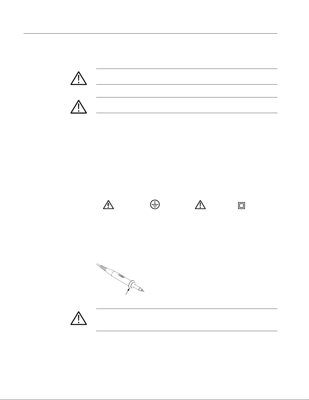
Symbols on the Product. The following symbols may appear on the product:
Probe Safety
DANGER
High Voltage
Protective Ground
(Earth) Terminal
ATTENTION
Refer to Manual
Double
Insulated
A guard around the probe body provides a finger barrier for protection from
electric shock.
Finger guard
WARNING. To avoid electric shock when using the probe, keep fingers behind the
guard on the probe body, and do not touch metallic portions of the probe head
while it is connected to a voltage source.
Connect the probe to the oscilloscope and connect the ground terminal to ground
before you take any measurements.
viii
TDS1000 and TDS2000 Series Digital Storage Oscilloscopes Service Manual
Page 13

Service Safety Summary
Only qualified personnel should perform service procedures. Read this Service
Safety Summary and the General Safety Summary before performing any service
procedures.
Do Not Service Alone. Do not perform internal service or adjustments of this
product unless another person capable of rendering first aid and resuscitation is
present.
Disconnect Power. To avoid electric shock, disconnect the main power by means
of the power cord or, if provided, the power switch.
Use Care When Servicing With Power On. Dangerous voltages or currents may
exist in this product. Disconnect power, remove battery (if applicable), and
disconnect test leads before removing protective panels, soldering, or replacing
components.
To avoid electric shock, do not touch exposed connections.
TDS1000 and TDS2000 Series Digital Storage Oscilloscopes Service Manual
ix
Page 14

Service Safety Summary
x
TDS1000 and TDS2000 Series Digital Storage Oscilloscopes Service Manual
Page 15

Environmental Considerations
This section provides information about the environmental impact of the
product.
Product End-of-Life
Handling
Observe the following guidelines when recycling an instrument or component:
Equipment Recycling. Production of this equipment required the extraction and
use of natural resources. The equipment may contain substances that could be
harmful to the environment or human health if improperly handled at the
product’s end of life. In order to avoid release of such substances into the
environment and to reduce the use of natural resources, we encourage you to
recycle this product in an appropriate system that will ensure that most of the
materials are reused or recycled appropriately.
The symbol shown to the left indicates that this product
complies with the European Union’s requirements
according to Directive 2002/96/EC on waste electrical and
electronic equipment (WEEE). For information about
recycling options, check the Support/Service section of the
Tektronix Web site (www.tektronix.com).
Mercury Notification. This product uses an LCD backlight lamp that contains
mercury. Disposal may be regulated due to environmental considerations. Please
contact your local authorities or, within the United States, the Electronics
Industries Alliance (www.eiae.org) for disposal or recycling information.
Restriction of Hazardous
Substances
TDS1000 and TDS2000 Series Digital Storage Oscilloscopes Service Manual
This product has been classified as Monitoring and Control equipment, and is
outside the scope of the 2002/95/EC RoHS Directive. This product is known to
contain lead, cadmium, mercury , and hexavalent chromium.
xi
Page 16

Environmental Considerations
xii
TDS1000 and TDS2000 Series Digital Storage Oscilloscopes Service Manual
Page 17

Preface
Related Manuals
The service manual for the TDS1000- and TDS2000-Series Digital Storage
Oscilloscopes provides instructions to verify the performance of, calibrate,
troubleshoot, and repair the oscilloscopes to the module level.
Unless noted otherwise, the term “oscilloscope” refers to all of the models in the
TDS1000 and TDS2000 series.
These manuals contain additional documentation for the oscilloscopes:
Extension module
User manual
Language
English 071-1064-XX 071-0409-XX 071-1075-XX
French 071-1065-XX* 071-0483-XX
German 071-1067-XX* 071-0485-XX
Italian 071-1066-XX* 071-0484-XX
Spanish 071-1068-XX* 071-0482-XX
Portuguese 071-1070-XX* 071-0486-XX
Japanese 071-1069-XX* 071-0488-XX
Korean 071-1073-XX* 071-0491-XX
Simplified Chinese 071-1071-XX* 071-0489-XX
Traditional Chinese 071-1072-XX* 071-0490-XX
Russian 071-1074-XX* 071-0487-XX
*These manuals contain a language overlay for the front-panel controls.
part number
instructions part
number
Programmer manual
part number
TDS1000 and TDS2000 Series Digital Storage Oscilloscopes Service Manual
xiii
Page 18

Preface
xiv
TDS1000 and TDS2000 Series Digital Storage Oscilloscopes Service Manual
Page 19

Specifications
Page 20

Page 21

Specifications
g
q
These specifications apply to all TDS1000- and TDS2000-series oscilloscopes.
To verify that an oscilloscope meets specifications, it must first meet the
following conditions:
H The oscilloscope must have been operating continuously for twenty minutes
within the specified operating temperature.
H You must perform the Do Self Cal operation, accessible through the Utility
menu, if the operating temperature changes by more than 5 °C.
H The oscilloscope must be within the factory calibration interval of one year.
Specifications begin in Table 1--1. All specifications are guaranteed unless noted
“typical.” Specifications that are marked with the n symbol are checked in the
chapter Performance Verification.
Table 1- 1: Oscilloscope specifications
Acquisition
Acquisition Modes Sample, Peak Detect, and Average
Acquisition Rate,
typical
Single Sequence Acquisition Mode Acquisition Stops After
Up to 180 waveforms per second, per channel (Sample acquisition mode, no measurements)
Sample, Peak Detect Single acquisition, all channels simultaneously
Average N acquisitions, all channels simultaneously. N is selectable from 4,
16, 64, and 128
Inputs
Input Coupling DC, AC, or GND
Input Impedance, DC
Coupled
P2200 Probe
Attenuation
Supported Probe
Attenuation Factors
TDS1000 and TDS2000 Series Digital Storage Oscilloscopes Service Manual
1MΩ ±2% in parallel with 20 pF ±3pF
1X, 10X
1X, 10X, 100X, 1000X
1- 1
Page 22

Specifications
g
C
ati
tBN
C
I
fth
val
x
ceeded,d
ama
cil
losc
a
y
Table 1- 1: Oscilloscope specifications (Cont.)
Inputs
Maximum Voltage Overvoltage Category* Maximum Voltage
Between Signal and
ommon
npu
Channel-to-Channel TDS1001 TDS1002, TDS2002, TDS2004 TDS1012, TDS2012, TDS2014, TDS2022, TDS2024
Common Mode
Rejection, typical
CAT I and CAT II 300 V
CAT III 150 V
RMS
RMS
Derate at 20 dB/decade above 100 kHz to 13 V peak AC at 3 MHz and above.
For non-sinusoidal waveforms, peak value must be less than 450 V. Excursion above 300 V should be less
than 100 ms duration.
RMS signal level including any DC component removed through AC coupling must be limited to 300 V.
ese
uesare e
100:1 at 60 Hz
20:1at20MHz
100:1 at 60 Hz
20:1at30MHz
ge to theos
ope m
result.
100:1 at 60 Hz
10:1at50MHz
Measured on MATH Ch1 -- Ch2 waveform, with test signal applied between signal and common of both
channels, and with the same VOLTS/DIV and coupling settings on each channel
Measured on MATH Ch3 -- Ch4 waveform for 4-channel models
Channel-to-Channel TDS1001 TDS1002, TDS2002, TDS2004 TDS1012, TDS2012, TDS2014 TDS2022, TDS2024
Crosstalk
≥ 100:1 at 20 MHz ≥ 100:1 at 30 MHz ≥ 100:1 at 50 MHz ≥ 100:1 at 100 MHz
Measured on one channel, with test signal applied between signal and common of the other channel, and
with the same VOLTS/DIV and coupling settings on each channel
Vertical
Digitizers 8-bit resolution (except when set to 2 mV/div), each channel sampled simultaneously
VOLTS/DIV Range 2 mV/div to 5 V/div at input BNC
Position Range 2 mV/div to 200 mV/div, ±2V
> 200 mV/div to 5 V/div, ±50 V
*
Refer to the Overvoltage Category description on page 1--10.
1- 2
TDS1000 and TDS2000 Series Digital Storage Oscilloscopes Service Manual
Page 23

Table 1- 1: Oscilloscope specifications
n
AnalogBandwidth
g
(50s/divto5s/div**)
,
n
DCGainAccurac
y
n
DCMeasurement
Vertical
Specifications
n Analog Bandwidth
in Sample and Average
modes at BNC or with
P2200 probe,
DC Coupled
Analog Bandwidth in TDS1001 TDS1002, TDS2002, TDS2004 TDS1012, TDS2012, TDS2014, TDS2022, TDS2024
Peak Detect mode
typical
Selectable Analog Bandwidth Limit, typical
Lower Frequency
Limit, AC Coupled
Rise Time at BNC, TDS1001 TDS1002, TDS2002, TDS2004 TDS1012, TDS2012, TDS2014 TDS2022, TDS2024
typical
Peak Detect Response** Captures 50% or greater amplitude of pulses ≥12 ns wide typical (50 s/div to 5 s/div) in the center 8
n DC Gain Accuracy
n DC Measurement
Accuracy, Average
Acquisition Mode
TDS1001 TDS1002, TDS2002, TDS2004 TDS1012, TDS2012, TDS2014 TDS2022, TDS2024
40 MHz{*
20 MHz* (when vertical scale is set to < 5 mV)
30 MHz{* 50 MHz{* 75 MHz{*
**
,
20 MHz* (when vertical scale is set to < 5 mV)
20 MHz*
≤ 10 Hz at BNC
≤ 1 Hz when using a 10X passive probe
< 8.4ns <5.8ns <3.5ns <2.1ns
vertical divisions
±3% for Sample or Average acquisition mode, 5 V/div to 10 mV/div
±4% for Sample or Average acquisition mode, 5 mV/div and 2 mV/div
Measurement Type Accuracy
Average of ≥ 16 waveforms with vertical
position at zero
Average of ≥ 16 waveforms with vertical
position not at zero
60 MHz{* 100 MHz{* 200 MHz{*
0 °Cto+40°C(32°F
to 104 °F)
160 MHz{*
0 °Cto+50°C(32°F
to 122 °F)
±(3% × reading + 0.1 div + 1 mV) when 10 mV/div or greater
is selected
±[3% × (reading + vertical position) + 1% of vertical position
+0.2div]
Add 2 mV for settings from 2 mV/div to 200 mV/div
Add 50 mV for settings from > 200 mV/div to 5 V/div
Volts Measurement
Repeatability, Average
Acquisition Mode
{ When vertical scale is set to ≥ 5mV.
* Bandwidth reduced to 6 MHz with a 1X probe.
** The oscilloscope reverts to Sample mode when the SEC/DIV (horizontal scale) is set from 2.5 s/div to 5 ns/div on 1 GS/s models,
or from 2.5 s/div to 2.5 ns/div on 2 GS/s models. The Sample mode can still capture 10 ns glitches.
Delta volts between any two averages of ≥
16 waveforms acquired under same setup
and ambient conditions
±(3% × reading + 0.05 div)
TDS1000 and TDS2000 Series Digital Storage Oscilloscopes Service Manual
1- 3
Page 24

Specifications
idth)
g
Table 1- 1: Oscilloscope specifications (Cont.)
Horizontal
Sample Rate Range TDS2022, TDS2024 TDS1001, TDS1002, TDS2004, TDS1012, TDS2002,
TDS2012, TDS2014
5S/sto2GS/s 5S/sto1GS/s
Waveform Interpolation (sin x)/x
Record Length 2500 samples for each channel
SEC/DIV Range TDS2022, TDS2024 TDS1001, TDS1002, TDS2004, TDS1012, TDS2002,
TDS2012, TDS2014
2.5 ns/div to 50 s/div, in a 1, 2.5, 5 sequence 5 ns/div to 50 s/div, in a 1, 2.5, 5 sequence
n Sample Rate and
Delay Time Accuracy
Delta Time Measurement Conditions Accuracy
Accuracy (Full Bandw
Position Range 5ns/divto10ns/div (--4 div × s/div) to 20 ms
±50 ppm over any ≥1 ms time interval
Single-shot, Sample mode ±(1 sample interval + 50 ppm × reading + 0.6 ns)
> 16 averages ±(1 sample interval + 50 ppm × reading + 0.4 ns)
Sample interval = s/div ÷ 250
25 ns/div to 100 s/div (--4 div × s/div) to 50 ms
250 s/divto50s/div (--4 div × s/div) to 50 s
TDS2022, TDS2024
2.5 ns/div (--4 div × s/div) to 20 ms
1- 4
TDS1000 and TDS2000 Series Digital Storage Oscilloscopes Service Manual
Page 25

Table 1- 1: Oscilloscope specifications
ggy
,
ggg
g
g
Trigger
Specifications
n Trigger Sensitiv-
ity, Edge Trigger Type
Trigger Sensitivity, Coupling Sensitivity
Edge Trigger Type
Trigger Level Range Source Range
Trigger Level Accura- Accuracies are for signals having rise and fall times ≥ 20 ns
cy, typical
SET LEVEL TO 50%,
typical
Default Settings,
Video Trigger
* Bandwidth reduced to 6 MHz with a 1X probe.
Coupling Sensitivity TDS1001, TDS1002,
TDS1012, TDS2002,
TDS2004, TDS2012, TDS2014
DC EXT 200 mV from DC to 100 MHz* 200 mV from DC to 100 MHz*
EXT/5 1 V from DC to 100 MHz* 1 V from DC to 100 MHz*
CH1, CH2,
CH3, CH4
AC Same as DC at 50 Hz and above
NOISE REJ Reduces the DC-coupled trigger sensitivity by 2 times for > 10 mv/div to 5 V/div
HF REJ Same as the DC-coupled limit from DC to 7 kHz, attenuates signals above 80 kHz
LF REJ Same as the DC-coupled limits for frequencies above 300 kHz, attenuates signals
below 300 kHz
CH1, CH2, CH3, and
CH4
EXT ±1.6 V
EXT/5 ±8V
Source Accuracy
Internal ±0.2 div × volts/div within ±4 divisions from center screen
EXT ±(6%ofsetting+40mV)
EXT/5 ±(6% of setting + 200 mV)
Operates with input signals ≥ 50 Hz
Coupling is AC and Auto except for a single sequence acquisition
±8 divisions from center of screen
1 div from DC to 10 MHz*, 1.5 div from 10 MHz to Full
TDS2022, TDS2024
350 mV from 100 MHz to 200 MHz*
1.75 V from 100 MHz to 200 MHz*
TDS1000 and TDS2000 Series Digital Storage Oscilloscopes Service Manual
1- 5
Page 26

Specifications
y,g
Table 1- 1: Oscilloscope specifications (Cont.)
Trigger
Sensitivity, Video Trig- Composite video signal
ger Type, typical
Signal Formats and
Field Rates, Video
Trigger Type
Holdoff Range 500 ns to 10 s
Pulse Width Trigger
Source Range
Internal Pk-pk amplitude of 2 divisions
EXT 400 mV
EXT/5 2V
Supports NTSC, PAL, and SECAM broadcast systems for any field or any line
Pulse Width
Trigger modes
Pulse Width
Trigger Point
Pulse Width Range Selectablefrom33nsto10s
Pulse Width
Resolution
Equal Guardband t > 330 ns: ±5% ≤ guardband < ±(5.1% + 16.5 ns)
Not Equal Guardband t > 330 ns: ±5% ≤ guardband < ±(5.1% + 16.5 ns)
Trigger Frequency Counter
Readout Resolution 6 digits
Accuracy (typical) ±51 ppm including all frequency reference errors and ±1 count errors
Frequency Range AC coupled, 10 Hz minimum to rated bandwidth
Trigger when < (Less than), > (Greater than), = (Equal), or ≠ (Not Equal);
Positive pulse or Negative pulse
Equal: The oscilloscope triggers when the trailing edge of the pulse crosses the trigger level.
Not Equal: If the pulse is narrower than the specified width, the trigger point is the trailing edge. Otherwise, the
oscilloscope triggers when a pulse continues longer than the time specified as the Pulse Width.
Less than: The trigger point is the trailing edge.
Greater than (also called time-out trigger): The oscilloscope triggers when a pulse continues longer than the
time specified as the Pulse Width.
16.5 ns or 1 part per thousand, whichever is larger
t ≤ 330 ns: guardband = ±16.5 ns
165 ns < t ≤ 330 ns: guardband = --16.5 ns/+33 ns
t ≤ 165 ns: guardband = ±16.5 ns
1- 6
TDS1000 and TDS2000 Series Digital Storage Oscilloscopes Service Manual
Page 27

Table 1- 1: Oscilloscope specifications (Cont.)
Trigger Frequency Counter
Signal Source Pulse Width or Edge Trigger modes: all available trigger sources
The Frequency Counter measures trigger source at all times, including when the oscilloscope acquisition is
halted due to changes in the run status, or acquisition of a single shot event has completed.
Pulse Width Trigger mode: The oscilloscope counts pulses of significant magnitude inside the 250 ms
measurement window that qualify as triggerable events, such as narrow pulses in a PWM pulse train if set to <
mode and the width is set to a relatively small time.
Edge Trigger mode: The oscilloscope counts all edges of sufficient magnitude and correct polarity.
Video Trigger mode: The Frequency Counter does not operate.
Measurements
Cursors Voltage difference between cursors (ΔV)
Time difference between cursors (ΔT)
Reciprocal of ΔTinHertz(1/ΔT)
Automatic Measurements
Frequency, Period, Mean, Pk-Pk, Cycle RMS, Min, Max, Rise Time, Fall Time, Pos Width, Neg Width
Specifications
Table 1- 2: Oscilloscope general specifications
Display
Display Type 145 mm (5.7 in) diagonal liquid crystal
Display Resolution 320 horizontal by 240 vertical pixels
Display Contrast Adjustable, temperature compensated
Backlight Intensity, typical 65 cd/m
Probe Compensator Output
Output Voltage, typical 5Vinto≥ 1MΩ load
Frequency, typical 1 kHz
Power Source
Source Voltage 100 -- 120 VAC
120 -- 240 VAC
Power Consumption Less than 30 W
Fuse 1 A, T rating, 250 V
2
( 10%) from 45 Hz through 440 Hz, CAT II
RMS
( 10%) from 45 Hz through 66 Hz, CAT II
RMS
TDS1000 and TDS2000 Series Digital Storage Oscilloscopes Service Manual
1- 7
Page 28

Specifications
p
Table 1- 2:
Environmental
Temperature Operating 0 °Cto+50°C(32°F to 122 °F)
Cooling Method Convection
Humidity +40 °C or below
Altitude Operating and Nonoperating 3,000 m (10,000 ft)
Random Vibration Operating 0.31 g
Mechanical Shock Operating 50 g, 11 ms, half sine
Mechanical
Size Height 151.4 mm (5.96 in)
Weight (approximate) When packaged for domestic shipment 3.6kg(8.0lbs)
Oscilloscope general specifications (Cont.)
Nonoperating -- 4 0 °Cto+71°C(--40°F to 159.8 °F)
(+104 °F or below)
+41° Cto+50° C
(106 °F to 122 °F)
Nonoperating 2.46 g
Width 323.8 mm (12.75 in)
Depth 124.5 mm (4.90 in)
≤ 90% relative humidity
≤ 60% relative humidity
from 5 Hz to 500 Hz, 10 minutes on each axis
RMS
from 5 Hz to 500 Hz, 10 minutes on each axis
RMS
Certifications and Compliances
EN 61326. EMC requirements for Class A electrical equipment for measurement,
control, and laboratory use. Annex D.
H IEC 61000--4--2. Electrostatic discharge immunity
H IEC 61000--4--3. RF electromagnetic field immunity
H IEC 61000--4--4. Electrical fast transient / burst immunity
H IEC 61000--4--5. Power line surge immunity
H IEC 61000--4--6. Conducted RF Immunity
H IEC 61000--4--11. Voltage dips and interruptions immunity
EN 61000- 3- 2. AC power line harmonic emissions
EN 61000- 3- 3. Voltage changes, fluctuations, and flicker
1
Emissions which exceed the levels required by this standard may occur when this
equipment is connected to a test object.
1
1- 8
TDS1000 and TDS2000 Series Digital Storage Oscilloscopes Service Manual
Page 29

Specifications
Australia / New Zealand
Declaration of Conformity
-EMC
EMC Compliance
FCC Compliance
Russian Federation
Peoples Republic of China
EC Declaration of
Conformity - Low Voltage
Complies with EMC provision of Radiocommunications Act per these standard(s):
H AS/NZS 2064.1/2. Industrial, Scientific, and Medical Equipment: 1992
Meets the intent of Directive 89/336/EEC for Electromagnetic Compatibility
when it is used with the product(s) stated in the specifications table. Refer to the
EMC specification published for the stated products. May not meet the intent of
the directive if used with other products.
Emissions comply with FCC 47 CFR, Part 15, Subpart B for Class A equipment.
This product was certified by the GOST ministry of Russia to be in compliance
with all applicable EMC regulations.
This product has received the Chinese Metrology Certification. (CMC).
Compliance was demonstrated to the following specification as listed in the
Official Journal of the European Communities:
U.S. Nationally
Recognized Testing
Laboratory Listing
Canadian Certification
Additional Compliance
Low Voltage Directive 73/23/EEC, amended by 93/68/EEC.
H EN 61010-1:2001. Safety requirements for electrical equipment for
measurement control and laboratory use.
H EN 61010-2-031:2002. Particular requirements for handheld probe assem-
blies for electrical measurement and test equipment.
H UL 61010B--1:2004, 2nd Edition. Standard for electrical measuring and test
equipment.
H UL 61010B--2--031:2003. Particular requirements for handheld probe
assemblies for electrical measurement and test equipment.
H CAN/CSA C22.2 No. 1010.1:1997. Particular requirements for electrical
equipment for measurement, control, and laboratory use. Part 1.
H CAN/CSA C22.2 No. 61010--2--031:1994. Particular requirements for
handheld probe assemblies for electrical measurement and test equipment.
H IEC 61010--1:2001. Safety requirements for electrical equipment for
measurement, control, and laboratory use.
TDS1000 and TDS2000 Series Digital Storage Oscilloscopes Service Manual
1- 9
Page 30

Specifications
H IEC 61010--031:2002. Particular requirements for handheld probe assemblies
for electrical measurement and test equipment.
Equipment Type
Pollution Degree
Descriptions
Test and measuring equipment.
A measure of the contaminates that could occur in the environment around and
within a product. Typically the internal environment inside a product is
considered to be the same as the external. Products should be used only in the
environment for which they are rated.
H Pollution Degree 1. No pollution or only dry, nonconductive pollution
occurs. Products in this category are generally encapsulated, hermetically
sealed, or located in clean rooms.
H Pollution Degree 2. Normally only dry, nonconductive pollution occurs.
Occasionally a temporary conductivity that is caused by condensation must
be expected. This location is a typical office/home environment. Temporary
condensation occurs only when the product is out of service.
H Pollution Degree 3. Conductive pollution, or dry, nonconductive pollution
that becomes conductive due to condensation. These are sheltered locations
where neither temperature nor humidity is controlled. The area is protected
from direct sunshine, rain, or direct wind.
H Pollution Degree 4. Pollution that generates persistent conductivity through
conductive dust, rain, or snow. Typical outdoor locations.
Pollution Degree
Installation (Overvoltage)
Category Descriptions
Overvoltage Category
1- 10
Pollution Degree 2 (as defined in IEC 61010-1). Note: Rated for indoor use only.
Terminals on this product may have different installation (overvoltage) category
designations. The installation categories are:
H Measurement Category IV . For measurements performed at the source of
low-voltage installation.
H Measurement Category III. For measurements performed in the building
installation.
H Measurement Category II. For measurements performed on circuits directly
connected to the low-voltage installation.
H Measurement Category I. For measurements performed on circuits not
directly connected to MAINS.
Overvoltage Category II (as defined in IEC 61010-1)
TDS1000 and TDS2000 Series Digital Storage Oscilloscopes Service Manual
Page 31

Operating Information
Page 32

Page 33

Operating Information
TDS1000- and TDS2000-series oscilloscopes are two- or four-channel instruments in small, lightweight, benchtop chassis that you can use to take
ground-referenced measurements.
In addition to a list of general features, this chapter covers:
H How to install your product
H How to add extended functions
H How to perform a brief functional check
H How to use the self-calibration routine
H How to restore factory default settings
For more detailed information about oscilloscope operation, refer to your user
manual.
TDS1000 and TDS2000 Series Digital Storage Oscilloscopes Service Manual
2--1
Page 34

Operating Information
General Features
Model Channels Bandwidth Sample rate Display
TDS1001 2 40 MHz 1.0 GS/s Monochrome
TDS1002 2 60 MHz 1.0 GS/s Monochrome
TDS1012 2 100 MHz 1.0 GS/s Monochrome
TDS2002 2 60 MHz 1.0 GS/s Color
TDS2004 2 60 MHz 1.0 GS/s Color
TDS2012 2 100 MHz 1.0 GS/s Color
TDS2014 4 100 MHz 1.0 GS/s Color
TDS2022 2 200 MHz 2.0 GS/s Color
TDS2024 4 200 MHz 2.0 GS/s Color
H Context-sensitive Help system
H Color or monochrome LCD display
H Selectable 20 MHz bandwidth limit
H 2500-point record length for each channel
H Autoset Menu
H Probe Check Wizard
H Cursors with readouts
H Trigger frequency readout
H Eleven automatic measurements
H Waveform averaging and peak detection
H Dual time base
H Math Fast Fourier Transform (FFT)
H Pulse Width trigger capability
H Video trigger capability with line-selectable triggering
H External trigger
2--2
H Setup and waveform storage
H Variable persistence display
TDS1000 and TDS2000 Series Digital Storage Oscilloscopes Service Manual
Page 35

Operating Information
H RS-232, GPIB, and Centronics ports with the optional TDS2CMA Commu-
nications Extension Module
H User interface in ten user-selectable languages
TDS1000 and TDS2000 Series Digital Storage Oscilloscopes Service Manual
2--3
Page 36

Operating Information
Installation
Power Cord
Use only power cords designed for your oscilloscope. Use a power source that
delivers 90 to 264 VAC
must deliver 90 to 132 VAC
, 45 to 66 Hz. If you have a 400 Hz power source, it
RMS
, 360 to 440 Hz.
RMS
Refertopage8--8intheReplaceable Parts chapter for a list of power cords
available from Tektronix. All power cords must be rated for > 3 Amps, 3 wire,
and have an 18 AWG (1.0 mm) Safety Ground lead, or larger.
Securing cable
2--4
Security Loop
Power cable
Figure 2--1: Routing the power cord and security cable
Use the built-in cable channels to secure both your oscilloscope and extension
module to your location.
TDS1000 and TDS2000 Series Digital Storage Oscilloscopes Service Manual
Page 37

Extension Modules
Operating Information
You can increase the feature set of your oscilloscope by inserting an extension
module. Refer to page 8--8 for more information. Figure 2--2 shows the proper
way to install and remove a module without bending the connecting pins.
For more information on extension modules, see your oscilloscope user manual.
CAUTION. Electrostatic discharge (ESD) can damage components in the
extension module and the oscilloscope. Do not operate your instrument with the
extension module connector exposed.
Module release tab
Remove
extension
module
Install
extension
module
Figure 2--2: Installing and removing an extension module
TDS1000 and TDS2000 Series Digital Storage Oscilloscopes Service Manual
2--5
Page 38

Operating Information
Functional Check
Perform this quick functional check to verify that your oscilloscope is operating
correctly.
ON/OFF
button
PASSED
CH1
PROBE COMP
1. Turn on the oscilloscope.
Wait until the display shows that all power-on tests passed. Push the DEFAULT
SETUP button. The default Probe menu attenuation setting is 10X.
2. Set the switch to 10X on the P2200 probe and connect the oscilloscope probe to
channel 1. To do this, align the slot in the probe connector with the key on the
CH1 BNC, push to connect, and twist to the right to lock the probe in place.
Attach the probe tip and reference lead to the PROBE COMP connectors.
3. Push the AUTOSET button. Within a few seconds, you should see a square
wave in the display (approximately 5 V at 1 kHz peak-to-peak).
Move the probe to the CH2 BNC. Repeat step 3. For four-channel models,
repeat step 3 for CH3 and CH4. A similar test, described below, can be
performed on the EXT TRIG connector, although the amplitude scale factor is
undefined.
2--6
Connect the probe to the EXT TRIG BNC. Attach the probe tip and reference
lead to the PROBE COMP connectors. Push TRIG MENU and push the top
option button to select Edge triggering. Then, push the second option button to
select Ext as the source. Finally, push and hold the front-panel TRIG VIEW
button. Once again, you should see a square wave in the display.
TDS1000 and TDS2000 Series Digital Storage Oscilloscopes Service Manual
Page 39

Self Calibration
SEC/DIV50
0
Default Setup
Operating Information
The self-calibration routine lets you quickly optimize the oscilloscope signal path
for maximum measurement accuracy. You can run the routine at any time but you
should always run the routine if the ambient temperature changes by 5 _Cor
more.
To compensate the signal path, disconnect any probes or cables from the channel
input connectors. Then, press the UTILITY button and select the Do Self Cal
option. Follow the on-screen instructions to proceed.
Table 2--1 lists the state of the oscilloscope after you press DEFAULT SETUP.
NOTE. When you push the DEFAULT SETUP button, the oscilloscope displays
the CH1 waveform and removes all other waveforms.
Table 2--1: Default settings
Menu or system Option, button or knob Default setting
ACQUIRE Sample, Peak Detect, and
Average
Averages: 4, 8, 16, 64, and
128
RUN/STOP RUN
CURSOR Type Off
Source CH1
Horizontal (voltage) +/-- 3.2 divs
Vertical (time) +/-- 4 divs
DISPLAY Type Vectors
Persist Off
Format YT
HORIZONTAL Window Main
Trig Knob Level
POSITION 0.00 s
Sample
16
s
Window Zone
TDS1000 and TDS2000 Series Digital Storage Oscilloscopes Service Manual
50 s
2--7
Page 40

Operating Information
Sourc
e
CH1
Windo
w
Hanning
Table 2--1: Default settings (Cont.)
Menu or system Default settingOption, button or knob
MATH Operation CH1 -- CH2
FFT operation:
Window
FFT Zoom
MEASURE Source CH1
Type None
TRIGGER Mode Type Edge
Edge TRIGGER Type Edge
Source CH1
Slope Rising
Mode Auto
Coupling DC
LEVEL 0.00 V
Video TRIGGER Type Video
Source CH1
Polarity Normal
Sync All Lines
Standard NTSC
Pulse Width TRIGGER Type Pulse
Hanning
X1
2--8
Source CH1
When =
Set Pulse Width 1.00 ms
Polarity Positive
Mode Auto
Coupling DC
Vertical system,
all channels
Coupling DC
BW Limit
Volts/Div Coarse
Probe 10X
Invert Off
POSITION 0.00 divs (0.00 V)
VOLTS/DIV 1.00 V
Off
TDS1000 and TDS2000 Series Digital Storage Oscilloscopes Service Manual
Page 41

The DEFAULT SETUP button does not reset the following:
H Language option
H Saved setup files
H Saved reference waveform files
H Display contrast
H Calibration data
H Printer setup
H RS-232 setup
H GPIB setup
Operating Information
TDS1000 and TDS2000 Series Digital Storage Oscilloscopes Service Manual
2--9
Page 42

Operating Information
2--10
TDS1000 and TDS2000 Series Digital Storage Oscilloscopes Service Manual
Page 43

Theory of Operation
Page 44

Page 45

Theory of Operation
This chapter describes the electrical operation of the TDS1000- and
TDS2000-series oscilloscopes to the module level. It describes the basic
operation of each functional circuit block shown in Figures 3--1 and 3--2. Of
necessity, the descriptions for the two and four channel units, and the color and
monochrome units, are slightly different.
TDS1000 and TDS2000 Series Digital Storage Oscilloscopes Service Manual
3--1
Page 46

Theory of Operation
AC Line
Power Supply
3
AC Line In
Backlight Power
(Color)
P3
Backlight Power
(Mono)
Through
chassis
Front Panel
12
Probe Comp
Probe Comp
CH1
CH2
Signal
J300
J350
P53
GND
GND
J202
P/O J203
P/O J203
A1 Main
GND
DC Out
&Line
Trigger
DC In
LCD
18 Pins
J101
J201
J690
P131
50
11
(Color)
16
J1
2
(Mono)
12
Extension
Module
TDS1000 (Mono)
TDS2000 (Color)
J90
1
J902
9
J2
24
J4
Display
Backlight
Display Control
RS-232
GPIB
J380
EXT
TRIG
Figure 3--1: Module-level block diagram (two channel)
3--2
TDS1000 and TDS2000 Series Digital Storage Oscilloscopes Service Manual
25
J3
CENTRONICS
Page 47

AC Line
Theory of Operation
Power Supply
3
AC Line In
Through
chassis
Front Panel
J1
12
Probe Comp
Signal
Probe Comp
GND
GND
A1 Main
GND
J1
J104 P/O J203
J104 P/O J203
Backlight Power
(Mono)
Backlight Power
(Color)
DC Out
&Line
Trigger
J101
DC In
J201
LCD
18 Pins
Not used
P3
2
11
Color Display
J90
1
Backlight
J902
16
Display Control
CH1
CH2
CH3
CH4
EXT
TRIG
J300
J990
J350
J600
J650
J680
Figure 3--2: Module-level block diagram (four channel)
50
Extension
Module
J1
25
24
9
RS-232
GPIB
CENTRONICS
J2
J4
J3
TDS1000 and TDS2000 Series Digital Storage Oscilloscopes Service Manual
3--3
Page 48

Theory of Operation
Main Board
The main board of a four-channel oscilloscope is essentially 2, two-channel
oscilloscopes tied together through a common microprocessor, and some special
interconnects to support combining the display and trigger systems. For this
reason, the focus of the main board discussion will be the two-channel system,
with differences noted as necessary.
At a minimum, the main board contains attenuators, an amplifier ASIC, a
digitizer/trigger system ASIC, a signal processing/display/system services ASIC,
RAM, flash PROM, a microprocessor, and special power supplies. For a
four-channel oscilloscope, the attenuators and ASICs are duplicated. Most of the
other aspects of the circuitry remain unchanged.
Acquisition System
Signals from the CH 1, CH 2 and other input connectors pass through attenuators
and an AC-coupling switch to the amplifier ASIC. The EXT TRIG input has an
abbreviated version of this path, lacking some of the attenuator settings and the
AC coupling switch.
The amplifier ASIC contains buffers and variable gain amplifiers, as well as
filters that provide 20 MHz bandwidth limiting. The task of the amplifier ASIC is
to convert from a 1 MΩ single-ended environment in the front end to a much
lower impedance differential (and thus less noise-sensitive) environment for the
acquisition process. The amplifier ASIC assures that the input signal is amplified
to approximately the correct level to allow the fullest possible use of the digitizer.
The acquisition ASIC contains samplers and peak detectors for each input
channel, a common amplifier, an A/D converter, and the trigger logic. The
digitized waveform samples are transferred to the processing and display ASIC.
In four-channel systems, the two acquisition ASICs are interconnected so that a
trigger on one ASIC can cause a trigger on the other.
The processor system adds the microprocessor and flash PROM to the processing
and display system. The processor system interprets the front-panel control
changes detected by the display ASIC, provides control parameters based upon
user setting requests, computes waveform measurements, and manages the
extension module interface. Saved setups, waveforms, and calibration constants
are stored in nonvolatile memory (NVRAM). The processor system shares
DRAM with the display system.
3--4
TDS1000 and TDS2000 Series Digital Storage Oscilloscopes Service Manual
Page 49

Theory of Operation
Processing and Display
System
Input Signal Interface
The processing and display system consists of the display ASIC, DRAM, and
system oscillator. Digitized acquisition samples are received by the display ASIC
and stored in DRAM. Once data are received by the display ASIC, various
corrections are applied, display rasterization is performed, and the waveform is
placed into a display buffer. At the same time, the waveform is being read from
the display buffers and written to the LCD. Additional circuitry in the display
ASIC supports scanning the front panel, handling DRAM refresh, providing the
processor clock, and performing various memory mapping tasks required by all
elementary microprocessor based systems. In a four-channel system, the two
display ASICs are interconnected so that one ASIC may provide display
information for the second.
The processing and display system handles some of the computational tasks.
Other tasks are performed by the processor system. Since all array processing is
performed in the processing and display system, no computations can be
performed that involve data from two different channel sets. Thus, subtracting
channel 3 data from channel 2 is prohibited. Channel 1 and Channel 2 data may
be combined in all of the supported ways.
BNC connectors are mounted on the main board for all signal inputs. The signal
inputs are compatible with the supplied P2200 probes.
Probe Compensation
External Trigger
Main Board Power
The PROBE COMP and ground terminals are provided for probe adjustment.
The EXT TRIG channel is processed on the chain containing the highest
numbered normal input channel.
To support various functions on the main board, a number of secondary power
supplies are generated. For the amplifier and acquisitions ASICs, the main board
creates a +2.5 V and --2.5 V supply. The +2.5 V supply is derived from the
+3.3 V logic supply. The --2.5 V supply is derived from the --4 V supply. A three
terminal regulator provides +5 V for option modules and the LCD display.
An additional power supply provides the LCD bias voltage which ranges from
+19 V to +28 V, depending on contrast setting and display type. This +28 V
supply has a temperature sensor on the front-panel board that varies the output
voltage of the supply to maintain contrast over a wide temperature range.
TDS1000 and TDS2000 Series Digital Storage Oscilloscopes Service Manual
3--5
Page 50

Theory of Operation
Power Supply
Display Module
The main power supply module for the TDS1000- and TDS2000-series
oscilloscopes is a wide input range universal supply. It is capable of providing
about 17 W of power for the oscilloscope while allowing the input to run from
about +90 V to +264 V. Input frequency ranges from 47 Hz to 440 Hz, which
allows operation in virtually all countries in the world and in a number of
off-grid environments such as military power on aircraft.
The secondary supplies from the power supply and the approximate current
draws are listed in the table on page 6--35 with the associated connector pins on
J101.
For information on voltages used in the oscilloscope, refer to the Troubleshooting
section of this manual.
Front Panel
Two-Channel
Oscilloscopes
The display module is a standard passive liquid crystal display (LCD). The
monochrome unit is patterned with 320 columns by 240 rows, and has the
associated drivers and backlight. The backlight is based on a 5 mA side light
fluorescent tube.
The color unit is patterned with 320 columns x 3 sub-columns by 240 rows and
has associated drivers and backlight. The backlight is based upon a 5 mA top
light fluorescent tube which runs a higher voltage and is longer to provide
sufficient extra light to overcome the higher loss associated with the color filters.
You can access all of the switches, position encoders, and LEDs on the front-panel board of two-channel oscilloscopes. Additionally, an IC on the front-panel
board provides buffering and multiplexing of switch signals to the main board.
Two signals and a sense line are provided by the main board to support the front
panel. One of these lines resets the scan; a second clocks the scan to the next
position; and the sense line receives the current state of the selected switch or
encoder position.
For the encoders, some amount of debouncing occurs inside the front-panel IC.
All key debouncing is handled in the display ASIC on the main board.
3--6
TDS1000 and TDS2000 Series Digital Storage Oscilloscopes Service Manual
Page 51

Theory of Operation
Four-Channel
Oscilloscopes
LEDs
Extension Modules
The front-panel board of the four channel units is effectively two panels in
parallel. The left side of the board is largely handled by the display ASIC for
channels 1 and 2. The right side of the board is handled by the channel 3 and 4
ASIC. Separate front-panel ICs support these data paths.
The LEDs are lighted to indicate an alternative use for the associated front-panel
knob. For more information, see the User Manual for this oscilloscope.
The LEDs are controlled by latching the value of the Channel 1--2 front panel
scan counter when the appropriate scan value is set.
Optional extension modules add the capability for the microprocessor to interface
with IEEE-488 (GPIB) controllers and RS-232 controllers, and provide a PC-like
parallel printer interface. These modules contain the necessary chips to provide
standard RS-232 and IEEE-488 states. The parallel port interface is controlled by
software without significant hardware assistance.
TDS1000 and TDS2000 Series Digital Storage Oscilloscopes Service Manual
3--7
Page 52

Theory of Operation
3--8
TDS1000 and TDS2000 Series Digital Storage Oscilloscopes Service Manual
Page 53

Performance Verification
Page 54

Page 55

Performance Verification
c
OscilloscopeCalibration
This chapter contains performance verification procedures for the specifications
marked with the n symbol. The following equipment, or a suitable equivalent,
is required to complete these procedures.
Required Equipment
Description
DC Voltage Source 17.5mVto7V,±0.5%
Leveled Sine Wave Generator 50 kHz and 200 MHz, ±3%
Time Mark Generator 10 ms period, ±10 ppm
Minimum
requirements
accuracy
amplitude accuracy
accuracy
Examples
Wavetek 9100 Universal
Calibration System with
Os
illoscopeCalibration
Module (Option 250)
Fluke 5500A Multi-product
Calibrator with Oscilloscope
Calibration Option (Option
5500A-SC)
50 Ω BNC Cable BNCmaletoBNCmale,
≈ 1 m (36 in) long
50 Ω BNC Cable BNCmaletoBNCmale,
≈ 25 cm (10 in) long
50 Ω Feedthrough
Termination
Dual Banana to BNC Adapter Banana plugs to BNC female Tektronix part number
BNC T Adapter BNC male to dual BNC
Splitter, Power Frequency range: DC to
Adapter (four required) Male N--to--female BNC Tektronix part number
Adapter Female N-- to--male BNC Tektronix part number
BNC male and female
connectors
female connectors
4 GHz. Tracking: >2.0%
Tektronix part number
012-0482-XX
Tektronix part number
012-0208-XX
Tektronix part number
011-0049-XX
103-0090-XX
Tektronix part number
103-0030-XX
Tektronix part number
015--0565--XX
103--0045--XX
103--0058--XX
TDS1000 and TDS2000 Series Digital Storage Oscilloscopes Service Manual
4- 1
Page 56

Performance Verification
Test Record
Serial
number
Test Passed Failed
Self Test
Oscilloscope tests Low limit Test result High limit
Channel 1 DC Gain Accuracy 5mV/div 33.6 mV 36.4 mV
Procedure performed by Date
200 mV/div 1.358 V 1.442 V
2V/div 13.58 V 14.42 V
Channel 2 DC Gain Accuracy 5mV/div 33.6 mV 36.4 mV
200 mV/div 1.358 V 1.442 V
2V/div 13.58 V 14.42 V
Channel 3 DC Gain Accuracy15mV/div 33.6 mV 36.4 mV
200 mV/div 1.358 V 1.442 V
2V/div 13.58 V 14.42 V
Channel 4 DC Gain Accuracy15mV/div 33.6 mV 36.4 mV
200 mV/div 1.358 V 1.442 V
2V/div 13.58 V 14.42 V
Channel 1 Bandwidth 2.12 V —
Channel 2 Bandwidth 2.12 V —
Channel 3 Bandwidth
Channel 4 Bandwidth
1
1
2.12 V —
2.12 V —
Sample Rate and Delay Time Accuracy -- 2 d i v s +2 divs
Channel 1 Edge Trigger Sensitivity Stable trigger —
Channel 2 Edge Trigger Sensitivity Stable trigger —
Channel 3 Edge Trigger Sensitivity
Channel 4 Edge Trigger Sensitivity
1
1
Stable trigger —
Stable trigger —
External Edge Trigger Sensitivity Stable trigger —
1
Channels 3 and 4 are only on four channel oscilloscopes.
4- 2
TDS1000 and TDS2000 Series Digital Storage Oscilloscopes Service Manual
Page 57

Performance Verification Procedures
Before beginning these procedures, two conditions must first be met:
H The oscilloscope must have been operating continuously for twenty minutes
within the operating temperature range specified.
H You must perform the Self Calibration operation described below. If the
ambient temperature changes by more than 5 °C, you must perform the Self
Calibration operation again.
The time required to complete the entire procedure is approximately one hour.
WARNING. Some procedures use hazardous voltages. To prevent electrical shock,
always set voltage source outputs to 0 V before making or changing any
interconnections.
Performance Verification
Self Test
Self Calibration
Check DC Gain Accuracy
This internal procedure is automatically performed every time the oscilloscope is
powered on. No test equipment or hookups are required. Verify that no error
messages are displayed before continuing with this procedure.
The self calibration routine lets you quickly optimize the oscilloscope signal path
for maximum measurement accuracy. You can run the routine at any time, but
you should always run the routine if the ambient temperature changes by 5 _Cor
more.
1. Disconnect any probes or cables from the CH1 and CH2 input connectors.
2. Press the UTILITY button and select the Do Self Cal option to start the
routine. The routine takes approximately one minute to complete.
3. Verify that self calibration passed.
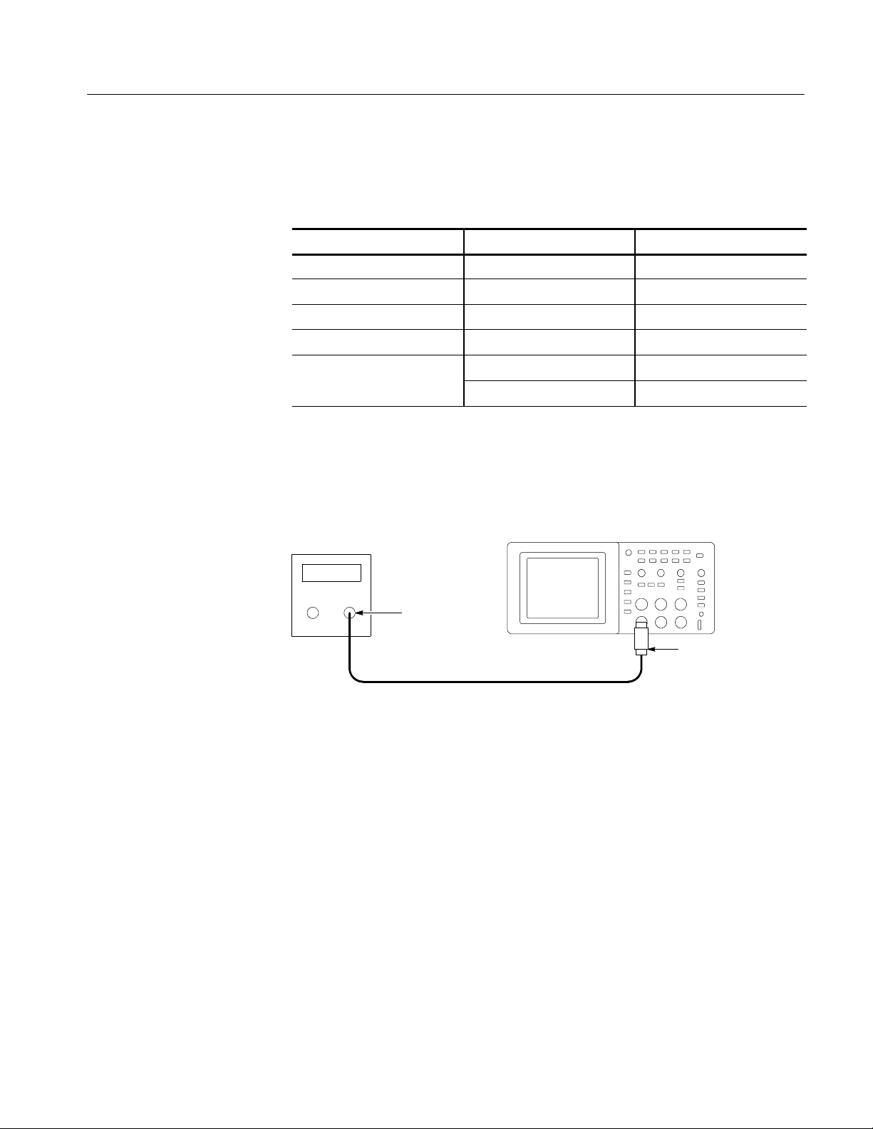
This test checks the DC gain accuracy of all input channels.
1. Set the DC voltage source output level to 0V.
2. Set up the oscilloscope using the following steps:
Press menu button Select menu option Select setting
1. DEFAULT SETUP — —
2. CH 1 Probe 1X
3. ACQUIRE Average 16
TDS1000 and TDS2000 Series Digital Storage Oscilloscopes Service Manual
4- 3
Page 58

Performance Verification
Press menu button Select settingSelect menu option
4. MEASURE
Source An unchecked channel
Type Mean
3. As shown below, connect the oscilloscope channel selected in the table to the
DC voltage source.
DC voltage
source
+--
Dual banana
to BNC
adapter
BNC cable
Digitizing oscilloscope
4. For each VOLTS/DIV setting listed below, perform the following steps:
a. Set the DC voltage source output level to the positive voltage listed and
then record the mean measurement as V
pos
.
b. Reverse the polarity of the DC voltage source and then record the mean
measurement as V
c. Calculate V
diff
=V
neg
pos
.
-- V
and then compare V
neg
to the accuracy
diff
limits in the table.
VOLTS/DIV setting DC voltage source output levels Accuracy limits for V
5mV/div +17.5 mV, --17.5 mV 33.6 mV to 36.4 mV
diff
4- 4
200 mV/div +700 mV, --700 mV 1.358 V to 1.442 V
2V/div +7.00 V, --7.00 V 13.58 V to 14.42 V
5. Set DC voltage source output level to 0V.
6. Disconnect the test setup.
7. Repeat steps 1 through 6 until all input channels have been checked.
TDS1000 and TDS2000 Series Digital Storage Oscilloscopes Service Manual
Page 59
Performance Verification
Check Bandwidth
This test checks the bandwidth of all input channels.
1. Set up the oscilloscope using the following steps:
Press menu button Select menu option Select setting
DEFAULT SETUP — —
CH 1 Probe 1X
ACQUIRE Average 16
TRIGGER Coupling Noise
MEASURE
Source An unchecked channel
Type Pk-Pk
2. As shown below, connect the oscilloscope channel selected in the table to the
leveled sine wave generator.
Leveled
sine wave
generator
Digitizing oscilloscope
Output
50 Ω feedthrough
BNC cable
terminator
3. Set the oscilloscope VOLTS/DIV to 500 mV/div.
4. Set the oscilloscope SEC/DIV to 10 s/div.
5. Set the leveled sine wave generator frequency to 50 k Hz.
6. Set the leveled sine wave generator output level so the peak-to-peak
measurement is between 2.98 V and 3.02 V.
7. Set the leveled sine wave generator frequency to:
H 40 MHz if you are checking a TDS1001
H 60 MHz if you are checking a TDS1002/2002/2004
H 100 MHz if you are checking a TDS1012/2012/2014
H 200 MHz if you are checking a TDS2022/2024.
TDS1000 and TDS2000 Series Digital Storage Oscilloscopes Service Manual
4- 5
Page 60

Performance Verification
8. Set the oscilloscope SEC/DIV to 10 ns/div.
9. Check that the peak-to-peak measurement is ≥2.12 V.
10. Disconnect the test setup.
11. Repeat steps 1 through 10 until all input channels have been checked.
Check Sample Rate and
Delay Time Accuracy
This test checks the time base accuracy.
1. Set up the oscilloscope using the following steps:
Press menu button Select menu option Select setting
DEFAULT SETUP — —
CH 1 Probe 1X
2. Connect the oscilloscope to the time mark generator as shown below.
Time mark
generator
Output
BNC cable
Digitizing oscilloscope
50 Ω feedthrough
terminator
4- 6
3. Set the time mark generator period to 10 ms.
4. Set the oscilloscope VOLTS/DIV to 500 mV/div.
5. Set the oscilloscope Main SEC/DIV to 1ms/div.
6. Press SET LEVEL TO 50%.
7. Use the vertical POSITION control to center the test signal on screen.
8. Use the horizontal POSITION control to set the position to 10.00 ms.
9. Set the oscilloscope SEC/DIV to 250 ns/div.
TDS1000 and TDS2000 Series Digital Storage Oscilloscopes Service Manual
Page 61

Performance Verification
10. Check that the rising edge of the marker crosses the center horizontal
graticule line within ±2 divisions of center graticule.
NOTE. One division of displacement from graticule center corresponds to
a 25 ppm time base error.
11. Disconnect the test setup.
Check Edge Trigger
Sensitivity
This test checks the edge trigger sensitivity for all input channels.
1. Set up the oscilloscope using the following steps:
Press menu button Select menu option Select setting
DEFAULT SETUP — —
CH 1 Probe 1X
TRIGGER Mode Normal
ACQUIRE Sample —
MEASURE
Source An unchecked channel
Type Pk-Pk
2. As shown below, connect the oscilloscope channel selected in the table to the
leveled sine wave generator.
Leveled
sine wave
generator
Digitizing oscilloscope
Output
BNC cable
3. Set the oscilloscope VOLTS/DIV to 500 mV/div.
4. Set the oscilloscope SEC/DIV to 25 ns/div.
TDS1000 and TDS2000 Series Digital Storage Oscilloscopes Service Manual
50 Ω feedthrough
terminator
4- 7
Page 62

Performance Verification
5. Set the leveled sine wave generator frequency to 10 MHz.
6. Set the leveled sine wave generator output level to approximately 500 mV
p-p
so that the measured amplitude is approximately 500 mV. (The measured
amplitude can fluctuate around 500 mV.)
7. Press SET LEVEL TO 50%. Adjust TRIGGER LEVEL as necessary and
then check that triggering is stable.
8. Set the leveled sine wave generator frequency to
H 40 MHz if you are checking a TDS1001
H 60 MHz if you are checking a TDS1002/2002/TDS2004
H 100 MHz if you are checking a TDS1012/2012/2014
H 200 MHz if you are checking TDS2022/2024.
9. Set the oscilloscope SEC/DIV to 10 ns/div.
10. Set the leveled sine wave generator output level to approximately 750 mV
p-p
so that the measured amplitude is approximately 750 mV. (The measured
amplitude can fluctuate around 750 mV.)
11. Press SET LEVEL TO 50%. Adjust TRIGGER LEVEL as necessary and
then check that triggering is stable.
12. Change the oscilloscope setup using the following step:
Press menu button Select menu option Select setting
TRIGGER Slope Falling
13. Press SET LEVEL TO 50%. Adjust TRIGGER LEVEL as necessary and
then check that triggering is stable.
14. Change the oscilloscope setup using the following step:
Press menu button Select menu option Select setting
TRIGGER Slope Rising
15. Disconnect the test setup.
16. Repeat steps 1 through 15 until all input channels have been checked.
4- 8
TDS1000 and TDS2000 Series Digital Storage Oscilloscopes Service Manual
Page 63

Performance Verification
Check External Edge
Trigger Sensitivity
This test checks the edge trigger sensitivity for the external trigger.
1. Set up the oscilloscope using the following steps:
Press menu button Select menu option Select setting
DEFAULT SETUP — —
CH 1 Probe 1X
TRIGGER
Source Ext
Mode Normal
ACQUIRE Sample —
MEASURE
Source CH1
Type Pk-Pk
2. Connect the oscilloscope to the leveled sine wave generator as shown below.
Leveled
sine wave
generator
Digitizing oscilloscope
Output
Power divider
Male SMA to
female BNC
SMA female-to--female
3Pieces
3. Set the leveled sine wave generator frequency to
H 40 MHz if you are checking a TDS1001
H 60 MHz if you are checking a TDS1002/2002/TDS2004
H 100 MHz if you are checking a TDS1012/2012/2014
H 200 MHz if you are checking TDS2022/2024.
4. Set the oscilloscope VOLTS/DIV to 100 mV/div.
5. Set the oscilloscope SEC/DIV to 10 ns/div.
50 Ω
feedthrough
terminator
TDS1000 and TDS2000 Series Digital Storage Oscilloscopes Service Manual
4- 9
Page 64

Performance Verification
6. Set the sine wave generator output level so that CH1 indicates approximately
200 mV
so that the measured amplitude is approximately 200 mV.(The
p-p
measured amplitude can fluctuate around 200 mV.) The output level of the
sine wave generator will be approximately 400 mV.
7. Press SET LEVEL TO 50%. Adjust TRIGGER LEVEL as necessary and
then check that triggering is stable.
8. For TDS2022 and TDS2024 models, set the sine wave generator frequency
to 200 MHz.
9. For TDS2022 and TDS2024 models, set the sine wave generator output level
for CH1 to approximately 350 mV
p-p
.
10. Press SET LEVEL TO 50%. Adjust TRIGGER LEVEL as necessary and
then check that triggering is stable.
11. Change the oscilloscope setup using the following step:
Press menu button Select menu option Select setting
TRIGGER Slope Falling
12. Press SET LEVEL TO 50%. Adjust TRIGGER LEVEL as necessary and
then check that triggering is stable.
13. Change the oscilloscope setup using the following step:
Press menu button Select menu option Select setting
TRIGGER Slope Rising
14. Disconnect the test setup.
4- 10
TDS1000 and TDS2000 Series Digital Storage Oscilloscopes Service Manual
Page 65

Adjustment Procedures
Page 66

Page 67

Adjustment Procedures
This chapter contains adjustment procedures for the TDS1000- and
TDS2000-series oscilloscopes.
Only qualified personnel should perform service procedures. Read the Service
Safety Summary and the General Safety Summary at the beginning of this manual
before performing any service procedures. Also refer to the chapter Operating
Information for information about using the TDS1000 and TDS2000 oscilloscopes.
NOTE. The voltage references inside the TDS1000 and TDS2000 oscilloscopes
are very stable over time and should not require routine updates. Before
performing any procedure in this chapter, first verify that the oscilloscope does
not meet specifications. Refer to the chapter Performance Verification to verify
the specifications.
Required Equipment
The equipment described in Table 5--1, or a suitable equivalent, is required to
complete these procedures.
Table 5--1: Required equipment
Description Minimum requirements Examples
DC Voltage Source -- 20 V t o 2 0 V, ±0.1% accuracy Wavetek 9100 Universal Calibration
System with Oscilloscope
Calibration Module (Option 250)
Leveled Sinewave
Generator
50 Ω BNC Cable
50 Ω BNC Cable (two)
50 Ω Feedthrough
Termination
60 kHz and 200 MHz, ±0.6%
amplitude accuracy
BNCmaletoBNCmale,
≈ 1 m (36 in) long
BNCmaletoBNCmale,
≈ 25 cm (10 in) long
BNC male and female
connectors
Fluke 5500A Multi-product
Calibrator with Oscilloscope
Calibration Option
(Option 5500A-SC)
Tektronix part number 012-0482-00
Tektronix part number 012-0208-00
Tektronix part number 011-0049-01
TDS1000 and TDS2000 Series Digital Storage Oscilloscopes Service Manual
5--1
Page 68

Adjustment Procedures
Table 5--1: Required equipment (Cont.)
Description ExamplesMinimum requirements
Dual Banana to BNC
Adapter
Banana plugs to BNC female Tektronix part number 103-0090-00
BNC T One male and two female
BNC connectors
Tektronix part number 103-0030-00
5--2
TDS1000 and TDS2000 Series Digital Storage Oscilloscopes Service Manual
Page 69

Adjustment Procedure
Adjustment Procedures
The adjustment procedure consists of 70 steps for the two-channel oscilloscope,
and 106 steps for the four-channel model. Each step requires an external voltage
source for new calibration constants.
Before performing the adjustment procedure, you must warm up the oscilloscope
for at least ten minutes in an ambient temperature between 20 °C and 30 °C.
Adjustments performed prior to warm-up or outside this temperature range may
result in poor performance.
If all steps in the procedure are completed successfully, a “Pass” message is
displayed and the new calibration constants take affect. If any step fails, the
procedure is aborted and the current calibration is not affected. You can choose to
abort the procedure at any step by selecting FCAL ABORT without affecting the
current calibration.
NOTE. While performing the adjustment procedure, keep in mind that some of the
steps take a significant amount of time (up to 5 minutes) to complete.
Enable the Service Menu
The equipment setups, shown in Figure 5--1, are required to complete the
adjustment procedure. Table 5--2 on page 5--6 lists the steps in the procedure
and the signal requirement for each step.
You must enable the Service menu to perform the adjustment procedure. To do
this:
1. Power on the oscilloscope.
2. Push the front-panel MEASURE button to access the MEASURE menu.
3. Push the top option button to access the Measure 1 menu.
4. Push and hold the front-panel SINGLE SEQ button.
5. Push and hold the front-panel AUTOSET button.
6. Wait at least two seconds.
7. Release the SINGLE SEQ button.
8. Release the AUTOSET button. A message appears in the lower left corner of
the screen stating “Service mode ON.”
9. Push the front-panel UTILITY button. The last item in the Utility menu is
now Service.
After the adjustment is complete, disable the Service menu by pushing the
UTILITY front-panel button, and the Service and Service Mode Off option
buttons.
TDS1000 and TDS2000 Series Digital Storage Oscilloscopes Service Manual
5--3
Page 70
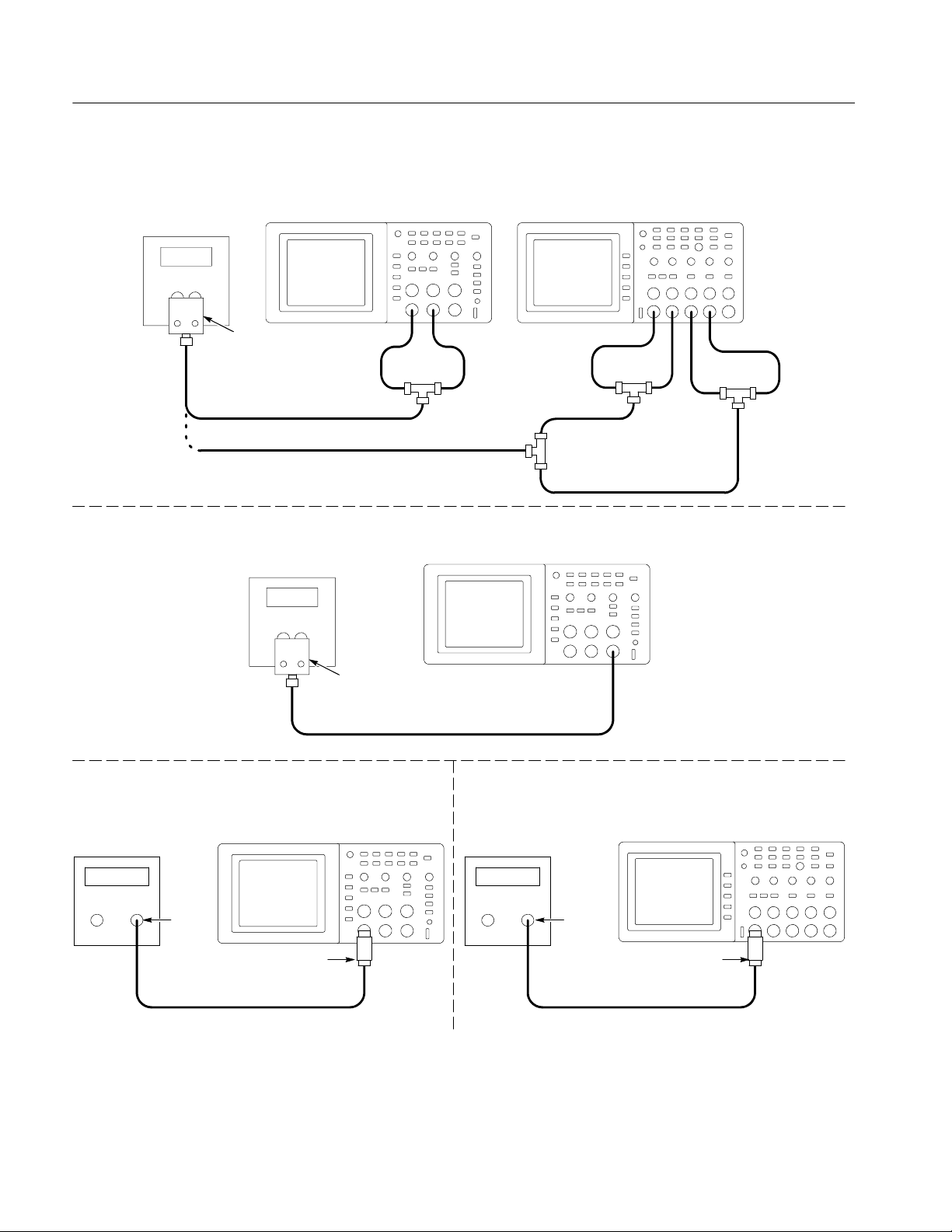
Adjustment Procedures
DC voltage setup 1
DC voltage source
+--
Dual banana to
BNC adapter
BNC cable
BNC cable
Two Channel
Digitizing oscilloscope
10-inch
BNC cables
BNC ‘T’ connector
Four Channel
Digitizing oscilloscope
10-inch
BNC cables
10-inch
BNC cable
BNC ‘T’
connector
10-inch BNC cable
10-inch
BNC cables
BNC ‘T’
connectors
DC voltage setup 2
Sinewave generator setup
Leveled sine
wave generator
Output
50 Ω feedthrough terminator
(Table 5--2 and 5--3 list
DC voltage source
+--
Two Channel
Digitizing oscilloscope
proper channel)
Dual banana to
BNC adapter
Two Channel
Digitizing oscilloscope
BNC cable
Edge setup
Square wave
generator
Four Channel
Digitizing oscilloscope
Output
50 Ω feedthrough terminator
(Table 5--2 and 5--3 list
proper channel)
BNC cable
Figure 5--1: Adjustment setups
5--4
BNC cable
TDS1000 and TDS2000 Series Digital Storage Oscilloscopes Service Manual
Page 71

Adjustment Procedures
Adjustment Procedure
Use this procedure to load new calibration constants.
1. Enable the Service menu as described on page 5--3.
2. Push the Service option button.
3. Push the Factory Cal option button.
4. Push the Warmup Timer option button.
5. Push the Start Timer option button to ensure a 10-minute warm up. After 10
minutes passes, the oscilloscope displays a large black or green cross.
6. Press the front-panel UTILITY button and push the Service option button.
7. Push the Factory Cal option button.
8. Push the FCAL INIT option button to initiate the factory calibration routine.
You are now in step 1 of the procedure.
9. As indicated by Step 1 in Table 5--2, connect a 0.0 V
source to the channel
DC
inputs.
10. Press FCAL STEP to load the calibration constant for step 1.
11. Follow the screen prompts along with Table 5--2 for the remainder of the
routine, applying the proper signal for each step.
NOTE. During some steps, the oscilloscope may appear to be idle for several
minutes while it is processing information internally. You must wait for the screen
prompt to continue.
If any step in the procedure fails, the procedure terminates. Failure will result
if an incorrect signal source is connected. If this happens, you must start the
procedure over from the beginning.
If the procedure completes successfully, a “Pass” message is displayed and
the new adjustment takes effect.
12. Compensate the signal path by performing the self-calibration routine.
Disconnect any probes or cables from the channel input connectors. Then,
press the UTILITY button and select Do Self Cal to confirm that you are
ready to proceed.
13. Disable the Service menu option by pushing the UTILITY front-panel
button, and the Service and Service Mode Off option buttons.
TDS1000 and TDS2000 Series Digital Storage Oscilloscopes Service Manual
5--5
Page 72

Adjustment Procedures
g
Table 5--2: Adjustment steps
Step
Two-channel
models
Refer to the DC voltage setup 1 diagram
1 1 DC Voltage 1 0.0 V
2 2 DC Voltage 1 --20.0 V
3 3 DC Voltage 1 -- 2 . 0 V
4 4 DC Voltage 1 -- 1 . 6 V
5 5 DC Voltage 1 -- 1 . 2 V
6 6 DC Voltage 1 -- 0 . 8 V
7 7 DC Voltage 1 -- 0 . 4 V
8 8 DC Voltage 1 --0.32 V
9 9 DC Voltage 1 -- 0 . 2 V
10 10 DC Voltage 1 --0.16 V
11 11 DC Voltage 1 --0.08 V
12 12 DC Voltage 1 --0.04 V
13 13 DC Voltage 1 --0.03 V
14 14 DC Voltage 1 --0.02 V
15 15 DC Voltage 1 --0.015 V
16 16 DC Voltage 1 0.015 V
17 17 DC Voltage 1 0.02 V
18 18 DC Voltage 1 0.03 V
19 19 DC Voltage 1 0.04 V
20 20 DC Voltage 1 0.08 V
21 21 DC Voltage 1 0.16 V
22 22 DC Voltage 1 0.2 V
23 23 DC Voltage 1 0.32 V
24 24 DC Voltage 1 0.4 V
25 25 DC Voltage 1 0.8 V
26 26 DC Voltage 1 1.2 V
27 27 DC Voltage 1 1.6 V
28 28 DC Voltage 1 2.0 V
29 29 DC Voltage 1 20.0 V
30 30 DC Voltage 1 0.0 V
Step
Four-channel
models
Signal Signal source setting Input
CH1 through
CHx
5--6
TDS1000 and TDS2000 Series Digital Storage Oscilloscopes Service Manual
Page 73

Table 5--2: Adjustment steps (Cont.)
S
i
O
hmBWL
V
5050SinewaveGenerator,50OhmBW
L,2.5
V
p-p
5151SinewaveGenerator,50OhmBW
L,5
V
p-p
Adjustment Procedures
Step
Two-channel
models
Step
Four-channel
models
Refer to the DC voltage setup 2 diagram
31 31 DC Voltage 2 -- 5 . 0 V
32 32 DC Voltage 2 -- 1 . 0 V
33 33 DC Voltage 2 1.0 V
34 34 DC Voltage 2 5.0 V
Refer to the Sinewave generator setup diagram. BWL refers the maximum bandwidth of the oscilloscope.
35 35 Sinewave Generator, 50 Ohm 5 kHz, 1 V
36 36 Sinewave Generator, 50 Ohm 1 MHz, 100 mV
37 37 Sinewave Generator, 50 Ohm 1MHz,1V
38 38 Sinewave Generator, 50 Ohm 50 kHz, 1 V
39 39 Sinewave Generator, 50 Ohm 20 MHz, 1 V
40 40
newaveGenerator, 50
41 41 Sinewave Generator, 50 Ohm BWL, 50 mV
42 42 Sinewave Generator, 50 Ohm BWL, 100 mV
43 43 Sinewave Generator, 50 Ohm BWL, 250 mV
44 44 Sinewave Generator, 50 Ohm BWL, 500 mV
45 40 Sinewave Generator, 50 Ohm BWL, 1 V
46 46 Sinewave Generator, 50 Ohm 5 kHz, 2.5 V
47 47 Sinewave Generator, 50 Ohm 1MHz,2.5V
48 48 Sinewave Generator, 50 Ohm 50 kHz, 2.5 V
49 49 Sinewave Generator, 50 Ohm 20 MHz, 2.5 V
,25m
p-p
p-p
p-p
p-p
p-p
p-p
p-p
p-p
p-p
p-p
p-p
p-p
p-p
p-p
p-p
InputSignal source settingSignal
EXT TRIG
CH1
52 52 Sinewave Generator, 50 Ohm BWL, 1.6 V
53 53 Edge, 50 Ohm. Refer to Edge setup
1 kHz, 0 to --800 mV
p-p
diagram.
TDS1000 and TDS2000 Series Digital Storage Oscilloscopes Service Manual
5--7
Page 74

Adjustment Procedures
S
i
O
hmBWL
V
6969SinewaveGenerator,50OhmBW
L,2.5
V
p-p
7070SinewaveGenerator,50OhmBW
L,5
V
p-p
Table 5--2: Adjustment steps (Cont.)
Step
Two-channel
models
54 54 Sinewave Generator, 50 Ohm 5 kHz, 1 V
Step
Four-channel
models
p-p
55 55 Sinewave Generator, 50 Ohm 1 MHz, 100 mV
56 56 Sinewave Generator, 50 Ohm 1MHz,1V
57 57 Sinewave Generator, 50 Ohm 50 kHz, 1 V
58 58 Sinewave Generator, 50 Ohm 20 MHz, 1 V
59 59
newaveGenerator, 50
60 60 Sinewave Generator, 50 Ohm BWL, 50 mV
,25m
p-p
p-p
p-p
p-p
p-p
61 61 Sinewave Generator, 50 Ohm BWL, 100 mV
62 62 Sinewave Generator, 50 Ohm BWL, 250 mV
63 63 Sinewave Generator, 50 Ohm BWL, 500 mV
64 64 Sinewave Generator, 50 Ohm BWL, 1 V
65 65 Sinewave Generator, 50 Ohm 5 kHz, 2.5 V
66 66 Sinewave Generator, 50 Ohm 1MHz,2.5V
p-p
p-p
p-p
67 67 Sinewave Generator, 50 Ohm 50 kHz, 2.5 V
68 68 Sinewave Generator, 50 Ohm 20 MHz, 2.5 V
InputSignal source settingSignal
CH2
p-p
p-p
p-p
p-p
p-p
p-p
5--8
TDS1000 and TDS2000 Series Digital Storage Oscilloscopes Service Manual
Page 75

Table 5--2: Adjustment steps (Cont.)
S
i
O
hmBWL
V
86SinewaveGenerator,50OhmBW
L,2.5
V
p-p
87SinewaveGenerator,50OhmBW
L,5
V
p-p
Adjustment Procedures
Step
Two-channel
models
NA
Step
Four-channel
models
71 Sinewave Generator, 50 Ohm 5 kHz, 1 V
p-p
72 Sinewave Generator, 50 Ohm 1 MHz, 100 mV
73 Sinewave Generator, 50 Ohm 1MHz,1V
74 Sinewave Generator, 50 Ohm 50 kHz, 1 V
75 Sinewave Generator, 50 Ohm 20 MHz, 1 V
76
newaveGenerator, 50
77 Sinewave Generator, 50 Ohm BWL, 50 mV
,25m
p-p
p-p
p-p
p-p
p-p
78 Sinewave Generator, 50 Ohm BWL, 100 mV
79 Sinewave Generator, 50 Ohm BWL, 250 mV
80 Sinewave Generator, 50 Ohm BWL, 500 mV
81 Sinewave Generator, 50 Ohm BWL, 1 V
82 Sinewave Generator, 50 Ohm 5 kHz, 2.5 V
83 Sinewave Generator, 50 Ohm 1MHz,2.5V
p-p
p-p
p-p
84 Sinewave Generator, 50 Ohm 50 kHz, 2.5 V
85 Sinewave Generator, 50 Ohm 20 MHz, 2.5 V
InputSignal source settingSignal
CH3
p-p
p-p
p-p
p-p
p-p
p-p
88 Sinewave Generator, 50 Ohm BWL, 1.6 V
89 Edge, 50 Ohm. Refer to Edge setup
1 kHz, 0 to --800 mV
diagram.
p-p
TDS1000 and TDS2000 Series Digital Storage Oscilloscopes Service Manual
5--9
Page 76

Adjustment Procedures
S
i
O
hmBWL
V
W
L
V
p-p
105SinewaveGenerato
r,50OhmBW
L,2.5
V
p-p
W
L,5V
p-p
106SinewaveGenerato
r,50OhmBW
L,5
V
p-p
Table 5--2: Adjustment steps (Cont.)
Step
Two-channel
models
NA
Step
Four-channel
models
90 Sinewave Generator, 50 Ohm 5 kHz, 1 V
p-p
91 Sinewave Generator, 50 Ohm 1 MHz, 100 mV
92 Sinewave Generator, 50 Ohm 1MHz,1V
93 Sinewave Generator, 50 Ohm 50 kHz, 1 V
94 Sinewave Generator, 50 Ohm 20 MHz, 1 V
95
newaveGenerator, 50
96 Sinewave Generator, 50 Ohm BWL, 50 mV
,25m
p-p
p-p
p-p
p-p
p-p
97 Sinewave Generator, 50 Ohm BWL, 100 mV
98 Sinewave Generator, 50 Ohm BWL, 250 mV
99 Sinewave Generator, 50 Ohm BWL, 500 mV
100 Sinewave Generator, 50 Ohm BWL, 1 V
101 Sinewave Generator, 50 Ohm 5 kHz, 2.5 V
102 Sinewave Generator, 50 Ohm 1MHz,2.5V
p-p
p-p
p-p
103 Sinewave Generator, 50 Ohm 50 kHz, 2.5 V
InputSignal source settingSignal
CH4
p-p
p-p
p-p
p-p
p-p
104 Sinewave Generator, 50 Ohm 20 MHz, 2.5 V
105 Sinewave Generator, 50 Ohm B
,2.5
106 Sinewave Generator, 50 Ohm B
p-p
5--10
TDS1000 and TDS2000 Series Digital Storage Oscilloscopes Service Manual
Page 77

Maintenance
Page 78

Page 79

Maintenance
Preparation
This chapter contains the information needed to do periodic and corrective
maintenance on the oscilloscope. The following sections are included:
H Preparation tells you how to get ready to do oscilloscope maintenance.
H Preventing ESD provides general information on preventing damage to
internal modules when doing maintenance.
H Inspection and Cleaning provides procedures for inspecting the oscilloscope
and cleaning its external and internal modules.
H Removal and Installation Procedures provides procedures for the removal
and installation of modules.
H Troubleshooting provides information for isolating failed modules.
H Repackaging Instructions provides packaging information for shipment or
storage.
Preventing ESD
Only qualified personnel should perform service procedures. Read the Service
Safety Summary and the General Safety Summary sections of this manual before
performing any service procedures. Also refer to the chapter Operating Information and your oscilloscope user manual for information about using the oscillo-
scope.
When performing any service which requires internal access to the oscilloscope,
adhere to the following precautions. These precautions will help you avoid
damaging internal modules and their components due to electrostatic discharge
(ESD).
CAUTION. Static discharge can damage any semiconductor component in this
oscilloscope.
H Minimize handling of static-sensitive modules.
H Transport and store static-sensitive modules in their static protected
containers or on a metal rail. Label any package that contains static-sensitive
modules.
TDS1000 and TDS2000 Series Digital Storage Oscilloscopes Service Manual
6--1
Page 80

Maintenance
Inspection and Cleaning
H Discharge the static voltage from your body by wearing a grounded antistatic
wrist strap while handling these modules.
H Service static-sensitive modules only at static-free workstations. Do not
allow anything capable of generating or holding a static charge on the
workstation surface.
H Handle circuit boards by the edges when possible.
H Do not slide the modules over any surface.
H Avoid handling modules in areas that have a floor or work-surface covering
capable of generating a static charge.
This section describes how to inspect for dirt and damage, and how to clean the
oscilloscope. Inspection and cleaning are done as preventive maintenance which,
when done regularly, may prevent malfunctions and enhance reliability.
General Care
Inspection and Cleaning
Procedures
Preventive maintenance consists of visually inspecting and cleaning the
oscilloscope, and using general care when operating it. Perform preventive
maintenance more often if you operate the oscilloscope in a severe environment.
A good time to perform preventive maintenance is just before adjustment of the
oscilloscope.
For optimum performance, follow these recommendations:
H Protect the oscilloscope from adverse weather conditions. The oscilloscope is
not waterproof.
H Do not store or leave the oscilloscope where the liquid crystal display (LCD)
will be exposed to direct sunlight or high humidity for long periods of time.
H The front and rear cases help keep dust out of the oscilloscope and must be in
place during normal operation.
H To avoid damage to the oscilloscope or probes, do not expose them to any
sprays, liquids, or solvents.
The collection of dirt on internal components can cause them to overheat and
fail. Dirt also provides an electrical conduction path that could cause an oscilloscope failure, especially under high-humidity conditions. Inspect and clean the
oscilloscope and probes as often as operating conditions require.
6--2
TDS1000 and TDS2000 Series Digital Storage Oscilloscopes Service Manual
Page 81
Maintenance
Inspection, Exterior. Inspect the outside of the oscilloscope for damage, wear, and
missing parts. Oscilloscopes that appear to have been dropped or otherwise
abused should be checked thoroughly to verify correct operation and performance. Immediately repair defects that could cause personal injury or lead to
further damage to the oscilloscope.
Cleaning Procedure, Exterior. To clean the oscilloscope exterior and probes:
1. Remove loose dust on the outside of the oscilloscope and probes with a
lint-free cloth. Use care to avoid scratching the clear glass display shield.
2. Use a soft cloth dampened with water to clean the oscilloscope, or use a 75%
isopropyl alcohol solution for more efficient cleaning.
CAUTION. To prevent getting moisture inside the oscilloscope during external
cleaning, use only enough liquid to dampen the cloth or applicator.
To avoid damage to the surface of the oscilloscope or probes, do not use any
abrasive or chemical cleaning agents.
Inspection, Interior. Inspect and clean the interior if it appears that the oscilloscope may have been damaged or exposed to an unusually dirty environment.
To inspect and clean the interior, disassemble the oscilloscope by completing
each of the disassembly procedures in the order given starting on page 6--6.
Inspect the internal portions of the oscilloscope for damage and wear using
Table 6--1 as a guide. Repair defects immediately.
Table 6--1: Internal inspection check list
Item Inspect for Repair action
Front and
Rear Case
Circuit boards Loose, broken, or corroded solder connec-
Solder
connections
Wiring and
cables
Cracks or deformations. Scratched lettering
or display filter. Loose connectors or labels.
tions. Burned circuit boards. Burned,
broken, or cracked circuit-run plating.
Cold solder or rosin joints. Resolder joint and clean with
Loose plugs or connectors. Burned, broken,
or frayed wiring.
Repair or replace defective
hardware.
Remove failed module and
replace with a new module.
isopropyl alcohol.
Firmly seat connectors. Repair or
replace modules with defective
wires or cables.
TDS1000 and TDS2000 Series Digital Storage Oscilloscopes Service Manual
6--3
Page 82

Maintenance
Cleaning Procedure, Interior. To clean the oscilloscope interior, perform the
following steps:
1. Blow off dust with dry, low-pressure, deionized air (approximately 9 psi).
2. Remove any remaining dust with a lint-free cloth dampened in isopropyl
alcohol (75% solution) and then wipe with a lint-free cloth dampened with
warm deionized water. A cotton-tipped applicator is useful for cleaning in
narrow spaces and on circuit boards.
STOP. If, after performing steps 1 and 2, a module is clean upon inspection, skip
steps 3 and 4. Proceed with step 5.
If steps 1 and 2 do not remove all the dust or dirt, all modules in the oscilloscope
except the Display Module and Front Panel Module may be spray washed using
a solution of 75% isopropyl alcohol.
Extensive cleaning of the Display Module is difficult because water must not be
trapped between the display shield and the display. The polarizers integrated into
the display degrade with long-term exposure to water. The display shield and
display must be replaced as an assembly if significant moisture or debris become
trapped inside. Cotton tipped applicators and lint-free rags moistened in
isopropyl alcohol and/or deionized water offer the best cleaning with the least
opportunity for damage to the assembly.
The Front Panel module can be damaged by deposition of film or debris inside
the knob encoders. To avoid this, care must be taken to not drip liquid or blow
debris into the encoders.
Proceed to step 3.
3. Spray wash dirty parts with the 75% isopropyl alcohol solution and wait 60
seconds for the majority of the alcohol to evaporate.
4. Use hot (49 _Cto60_C / 120 _F to 140 _F) deionized water to thoroughly
rinse the parts.
5. Dry all parts with low-pressure, deionized air.
6. Dry all components and assemblies in an oven or drying compartment using
low-temperature (52 _Cto66_C / 125 _F to 150 _F) circulating air.
Lubrication. Periodic lubrication is not required for the oscilloscope.
6--4
TDS1000 and TDS2000 Series Digital Storage Oscilloscopes Service Manual
Page 83

Removal and Installation Procedures
This section describes how to remove and install the major mechanical and
electrical modules. It provides the following information:
H Required Tools on page 6--6 describes the tools needed to perform the
procedures.
H List of Modules on page 6--5 describes where to locate a list of replaceable
modules.
H Summary of Procedures on page 6--6 lists the procedures for removal and
installation of modules.
H Rear Feet, on page 6--7, begins a series of procedures that describe the
removal and installation of modules.
Maintenance
Preparation
Read this section to prepare for module removal and installation.
WARNING. Only qualified personnel should perform service procedures. Before
doing this or any other procedure in this manual, read the General Safety
Summary and Service Safety Summary found at the beginning of this manual.
Always disconnect the power cord before disassembling any portion of the
oscilloscope.
To prevent damage to electrical components, read Preventing ESD on page 6--1.
H See Figure 8--1 on page 8--7 for an overview of how the entire oscilloscope is
assembled.
H Read the Summary of Procedures on page 6--6 to understand which
procedure to use to access a given module. Then read Required Tools on
page 6--6 for a list of tools needed to remove and install modules in the
oscilloscope.
H If you are disassembling the oscilloscope for cleaning, refer to Inspection
and Cleaning on page 6--2 for cleaning instructions.
List of Modules
TDS1000 and TDS2000 Series Digital Storage Oscilloscopes Service Manual
The Replaceable Parts List provides a list of all replaceable modules. Any
electrical or mechanical module, assembly, or part listed in the parts list is
referred to as a module.
6--5
Page 84

Maintenance
Summary of Procedures
Complete disassembly is best achieved by following the procedures in the order
given in Table 6--2 .
Table 6--2: List of procedures
Procedure Begins on page
Rear Feet 6--7
Flip Feet 6--9
Front-Panel Knobs 6--10
Power Button 6--10
Rear Case 6--10
Front Feet 6--14
Power Supply Module 6--15
Internal Assembly 6--17
Display Cable 6--19
Front-Panel Cable 6--21
Main Board Module 6--22
Display Module 6--24
Front-Panel Module 6--26
Required Tools
Keypad 6--28
Front Case 6--30
Use the following tools to remove and replace all modules in the oscilloscope:
H Torque-limiting screwdriver, long shank, 12 in-lb (1.3 N
⋅m) range with
Torx® T-15 tip
H 9/16 inch deep socket with wide center hole (S
⋅K Hand Tool Corp., S-K
#40818, or equivalent)
H Torque wrench to 40 in-lb (4.5 N
⋅m)
H Screwdriver with 1/4 inch flat blade
H Pliers (all-purpose and needle-nose)
H Sharp knife (X-ACTO
® knife or equivalent)
6--6
TDS1000 and TDS2000 Series Digital Storage Oscilloscopes Service Manual
Page 85

Maintenance
Rear Feet
You will need a flat-blade screwdriver to remove the rear feet.
Removal. To remove the rear feet, refer to Figure 6--1 and follow these steps:
1. Place the oscilloscope face down on a soft surface such as an anti-static mat.
2. Use a flat-blade screwdriver to pry out the foot, or twist the foot as you are
removing it so that it disengages from the guides. Use care not to mar the
surface of the rear case.
Figure 6--1: Removing the rear feet
TDS1000 and TDS2000 Series Digital Storage Oscilloscopes Service Manual
6--7
Page 86

Maintenance
Installation. To install the rear feet, refer to Figure 6--2 and follow these steps:
1. Place the oscilloscope face down on a soft surface such as an anti-static mat.
2. Align the slots of the rear foot with the guides in the rear case and press the
foot in.
6--8
Figure 6--2: Installing the rear feet
TDS1000 and TDS2000 Series Digital Storage Oscilloscopes Service Manual
Page 87

Maintenance
Flip Feet
You will need a pair of needle-nose pliers to remove the flip feet.
Removal. To remove the flip feet, refer to Figure 6--3 and follow these steps:
1. Place the oscilloscope face down on a soft surface such as an anti-static mat.
2. Grip the flip foot with the pliers as close to the notches as possible and
squeeze gently on the foot.
3. Twist slightly to swing one hinge free of the slot.
Hinge
To remove foot, squeeze at notches
and swing one hinge free of slot
Figure 6--3: Removing and installing the flip feet
To install foot, place hinge of
foot into one slot, then
swing other hinge into place
TDS1000 and TDS2000 Series Digital Storage Oscilloscopes Service Manual
6--9
Page 88

Maintenance
Installation. To install the flip feet, refer to Figure 6--3 and follow these steps:
1. Place the oscilloscope face down on a soft surface such as an anti-static mat.
2. Hold the flip foot with the smooth side facing down.
3. Gently squeeze the foot so that the hinge on one side fits into the slot, and
twist slightly to snap into the slot on the other side.
Front-Panel Knobs
Power Button
Rear Case
Remove each front-panel knob by firmly grasping the knob (with pliers if
necessary) and pulling it away from the front panel.
NOTE. Wrap the plier jaws with tape (such as electrical) to avoid marring the
knob surface.
Install front-panel knobs by aligning the keyed knob with the shaft and pressing
the knob onto the shaft.
Remove the power button by firmly grasping the button (with pliers if necessary)
and pull it straight out of the cabinet.
NOTE. Wrap the plier jaws with tape (such as electrical) to avoid marring the
button surface.
Install the button by pressing it onto the power button shaft until it snaps into
place.
You will need a torque-limiting Torx T-15 screwdriver and pliers for this
procedure.
6--10
Removal. To remove the rear case, refer to Figure 6--4 and follow these steps:
1. Remove the power button using the procedure on page 6--10.
2. If installed, remove the extension module from the rear of the oscilloscope.
For instructions, refer to the TDS1000- and TDS2000-Series User Manual.
CAUTION. To avoid damage, do not remove the rear case with an extension
module installed.
3. Place the oscilloscope face down on a soft surface such as an anti-static mat.
TDS1000 and TDS2000 Series Digital Storage Oscilloscopes Service Manual
Page 89
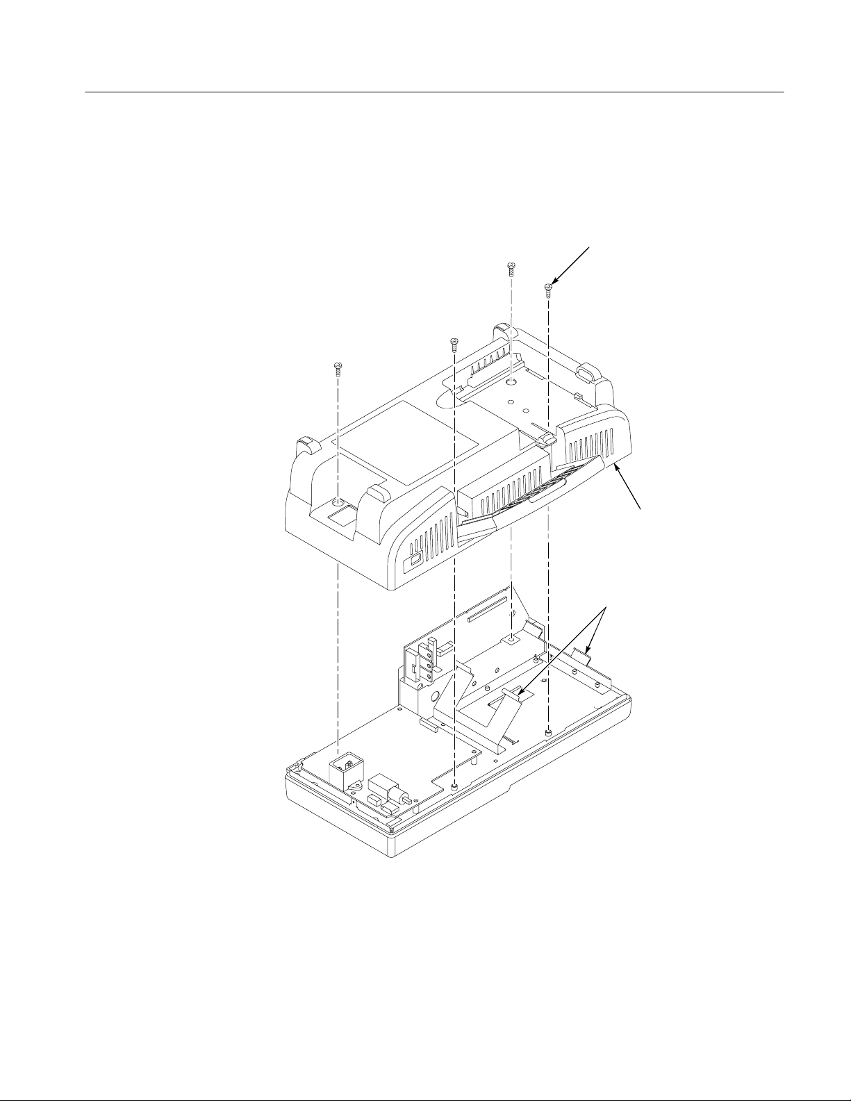
Maintenance
4. Remove the four screws located on the rear case. Tilt the handle to gain
better access to the top two screws.
5. Lift the rear case off of the oscilloscope.
Remove rear case
screws (4)
ESD Grounding ears
Figure 6--4: Removing and installing the rear case
Rear case
TDS1000 and TDS2000 Series Digital Storage Oscilloscopes Service Manual
6--11
Page 90
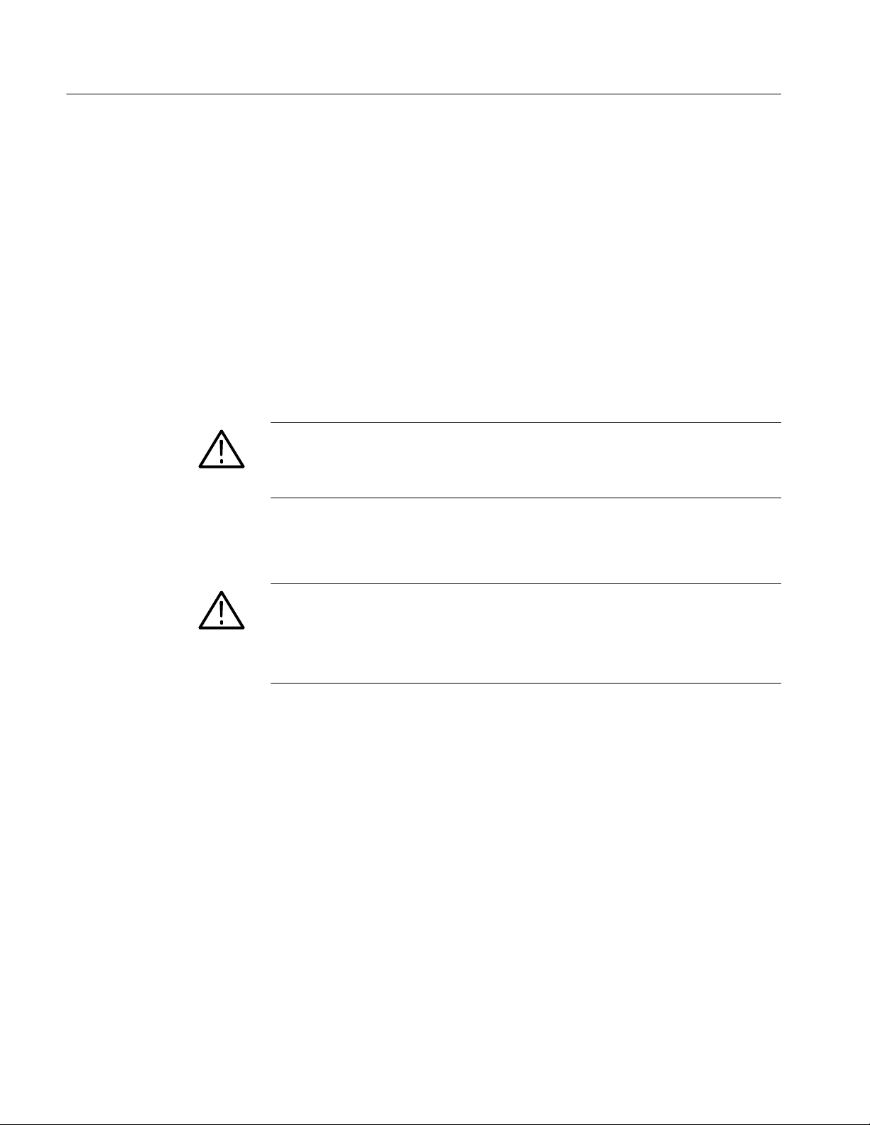
Maintenance
Installation. Use this procedure to install the rear case.
1. Place the oscilloscope face down on a soft surface (such as an anti-static
mat).
2. Place the rear case onto the assembled oscilloscope and ensure that:
H All of the edges align with the front case.
H The ESD grounding ears align with the rear case slots. If not, they must
be bent into the correct position. Figure 6--5 shows proper alignment.
H The notches on the edge of the main board module align with ridges on
the rear case near the extension module connector slot. Figure 6--5 shows
the location of the notches.
CAUTION. Failure to properly align the ESD grounding ears may result in ESD
damage to the extension module and/or the oscilloscope. Refer to Figure 6--5.
Be careful not to pinch any wires or other parts between the front and rear cases.
3. Install the four screws in the rear case. Tilt the handle to better access the top
two holes.
CAUTION. Avoid cross threading the screws that secure the rear case to the front
case. An easy way to avoid this is to slip the screw into the hole and, using slight
pressure, slowly rotate the screw counterclockwise until you feel the screw slip
into the screw threads. Then tighten the screw clockwise. A properly started
screw will have very little resistance going in.
4. Install the power button as described on page 6--10.
6--12
TDS1000 and TDS2000 Series Digital Storage Oscilloscopes Service Manual
Page 91
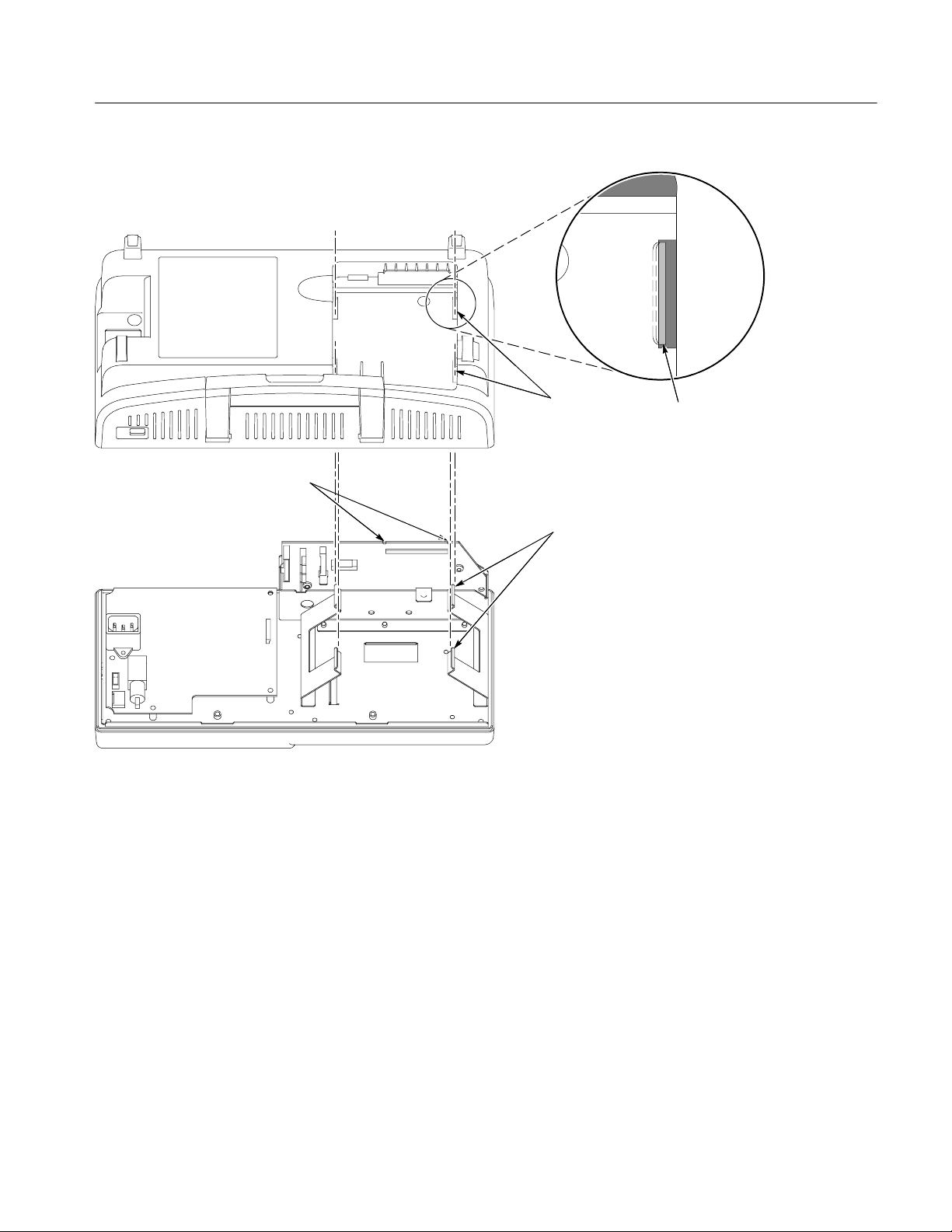
Maintenance
Main board notches
Figure 6--5: Aligning the oscilloscope rear case
Rear case
slots (4)
ESD grounding ears (4)
ESD grounding ears are properly
aligned with the rear case slots when
they are visible in approximately one
half the width of the slots.
TDS1000 and TDS2000 Series Digital Storage Oscilloscopes Service Manual
6--13
Page 92

Maintenance
Front Feet
You will need a torque-limiting Torx T-15 screwdriver and pliers for this
procedure.
Removal. First, remove the power button and rear case using the procedures on
page 6--10. Then, slide the front feet out of the front case as shown in Figure 6--6.
Installation. Slide the feet into the slots provided in the front case as shown in
Figure 6--6. Use the installation procedures for each module removed to
reassemble the oscilloscope.
Front foot
6--14
Figure 6--6: Removing and installing the front feet
TDS1000 and TDS2000 Series Digital Storage Oscilloscopes Service Manual
Page 93

Maintenance
Power Supply Module
Use a torque-limiting Torx T-15 screwdriver and pliers for this procedure.
Removal. To remove the module, refer to Figure 6--7 and follow these steps:
1. Remove the power button and rear case using the procedures on page 6--10.
2. Disconnect the following wires:
H The ground wire on the power supply module from the chassis ground
lug.
H The two-conductor backlight cable on the power supply module.
H The power supply ribbon cable on the main board at J101. Press down on
the latch while pulling up on the cable.
3. Remove the four screws connecting the power supply module to the chassis
and lift the module from the internal assembly.
Remove screws (4)
Power supply
ribbon cable
Ground wire
Backlight connector
(monochrome LCD)
Backlight cable
(color LCD)
Figure 6--7: Removing the power supply module
TDS1000 and TDS2000 Series Digital Storage Oscilloscopes Service Manual
6--15
Page 94
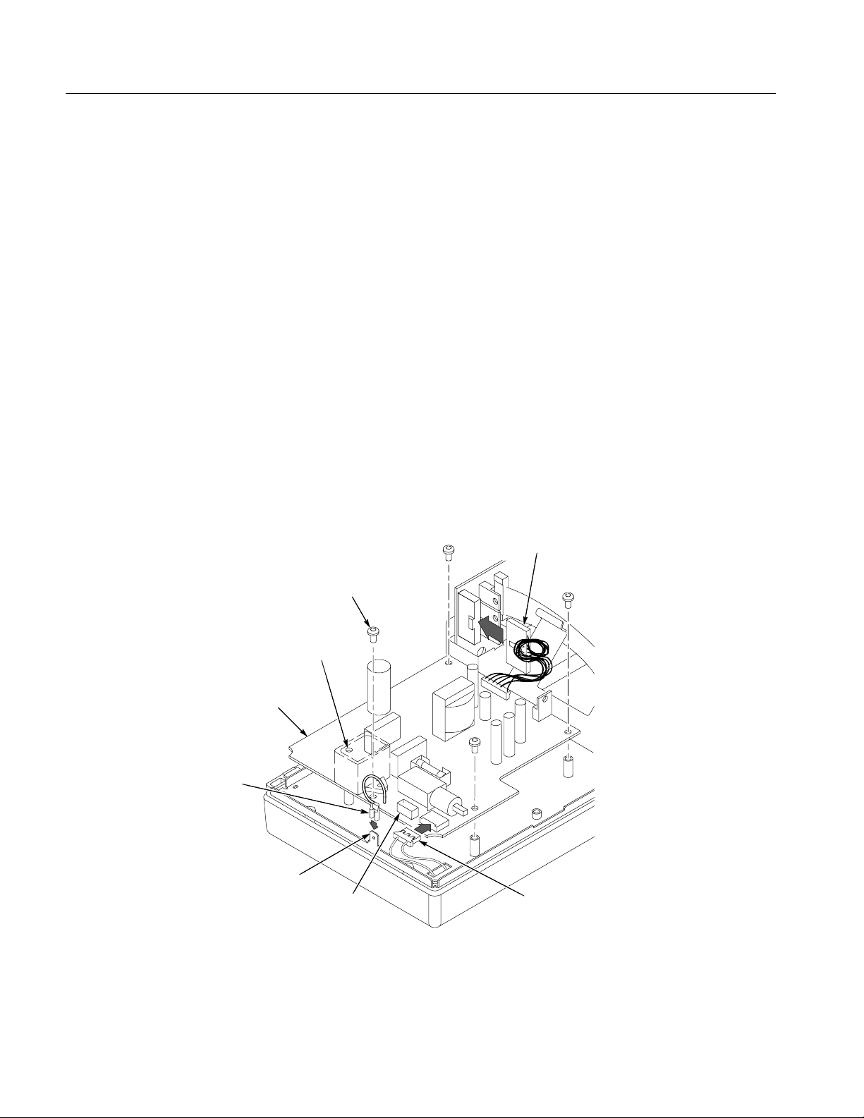
Maintenance
Installation. To install the power supply module, refer to Figure 6--8 and follow
these steps:
1. Align and place the power supply module into the internal assembly.
2. Install the four screws. Do not put a screw into the empty hole in Figure 6--8.
3. Reconnect the following wires:
H The ground wire on the power supply module to the chassis ground lug.
You may need to use pliers to secure the wire in place.
H The two-conductor backlight cable on the power supply module.
Connect to the black socket for a monochrome LCD, and to the white
socket for a color LCD.
H The power supply ribbon cable to the main board at J101. Twist the cable
four revolutions to keep it from contact with the boards and chassis.
4. Use the installation procedure for each module removed to reassemble the
oscilloscope.
Power supply module
Power supply ground wire
Chassis ground lug
Install screws (4)
Empty hole
NO SCREW
Backlight connector
(monochrome LCD)
Power supply
ribbon cable
Backlight cable
(color LCD)
6--16
Figure 6--8: Installing the power supply module
TDS1000 and TDS2000 Series Digital Storage Oscilloscopes Service Manual
Page 95

Maintenance
Internal Assembly
You will need a torque-limiting Torx T-15 screwdriver and a flat-blade screwdriver for this procedure.
Removal. To remove the assembly, refer to Figure 6--9 and follow these steps:
1. Remove the front-panel knobs, power button, and rear case using the
procedures on page 6--10.
2. Remove the four screws attaching the internal assembly to the front case.
3. Lift the entire internal assembly (consisting of the chassis, all of the boards,
and the display screen) out of the front case.
NOTE. The switch keypad will most likely remain inside the front case. It does not
need to be removed with the internal assembly.
Remove screws (4)
Figure 6--9: Removing and installing the internal assembly
TDS1000 and TDS2000 Series Digital Storage Oscilloscopes Service Manual
Internal
assembly
Front case
6--17
Page 96

Maintenance
Installation. To install the internal assembly, refer to Figure 6--9 and follow these
steps:
1. Use the installation procedure for each module removed to reassemble the
oscilloscope.
2. Place the internal assembly into the front case.
3. Install the four screws to attach the internal assembly to the front case.
6--18
TDS1000 and TDS2000 Series Digital Storage Oscilloscopes Service Manual
Page 97

Maintenance
Display Cable
You will need a torque-limiting Torx T-15 screwdriver and pliers for this
procedure.
Removal. To remove the display cable, refer to Figure 6--10 and follow these
steps:
1. Remove the power button and rear case using the procedures on page 6--10.
2. Untwist the cable tie to release the display cable.
3. Disconnect the display cable at J201 on the main board by pulling straight up
from the connector.
4. Disconnect the display cable on the display module by pulling it through the
horizontal slot on the chassis.
Main board J201
Figure 6--10: Removing the display cable
TDS1000 and TDS2000 Series Digital Storage Oscilloscopes Service Manual
Display cable
Display cable slot on
the chassis
6--19
Page 98

Maintenance
Installation. To install the display cable, refer to Figure 6--11 and follow these
steps:
1. Remove the display module using the procedure on page 6--24.
2. Attach the display cable to the appropriate connector on the display module
at the location shown in Figure 6--11: 12-pin for the monochrome display,
and 15-pin for the color display.
3. With the display module in place but not connected, thread the display cable
through the appropriate slot on the chassis.
4. Twist the cable two revolutions to keep it from contact with the boards and
chassis, and secure using the left cable tie.
5. Connect the display cable at J201 on the main board by pushing the cable
straight down into the connector.
6. Install the four screws to attach the display module to the internal assembly.
Display
module
Display cable
Figure 6--11: Installing the display cable
Internal
assembly
Main
board
6--20
TDS1000 and TDS2000 Series Digital Storage Oscilloscopes Service Manual
Page 99

Maintenance
Front-Panel Cable
You will need a torque-limiting Torx T-15 screwdriver and pliers for this
procedure.
Removal. To remove the front-panel cable, refer to Figure 6--12 and follow these
steps:
1. Remove the power button and rear case using the procedures on page 6--10.
2. Untwist the cable tie to release the front-panel cable.
3. Disconnect the front-panel cable at J202 on the main board by pulling
straight up from the connector.
4. Disconnect the front-panel cable at J1 on the front-panel module.
Front-panel cable
Main board
J202
Front-panel
module J1
Figure 6--12: Removing and installing the front-panel cable
TDS1000 and TDS2000 Series Digital Storage Oscilloscopes Service Manual
6--21
Page 100
Maintenance
Installation. To install the front-panel cable, refer to Figure 6--12 and follow these
steps:
1. Connect the front-panel cable to the front-panel module at J1 through the
appropriate slot on the chassis.
2. Twist the cable two revolutions to keep it from contact with the boards and
chassis, and secure using the right cable tie.
3. Connect the front-panel cable at J202 on the main board by pushing the cable
straight down into the connector.
Main Board Module
You will need a torque-limiting Torx T-15 long shank screwdriver, a torque
wrench, and a 9/16 inch deep socket for this procedure.
CAUTION. The main board module is particularly sensitive to ESD. Read the
Preventing ESD section on page 6--1 before removing or installing the main
board.
Removal. To remove the main board module, refer to Figure 6--13 and follow
these steps:
1. Remove the power button and rear case using the procedures on page 6--10.
2. Remove the internal assembly from the front case using the procedure on
page 6--17.
3. Disconnect the following wires from the main board by pulling straight up
from the connector:
H The power supply ribbon cable at J101. Press down on the latch while
pulling up on the cable.
H The display cable at J201.
6--22
H The front-panel cable at J202.
4. Use the screwdriver to remove the two screws attaching the main board
module to the internal assembly.
5. Use the socket to remove the nuts and washers from the BNC connectors.
6. Pull the board out from the front slots of the internal assembly.
TDS1000 and TDS2000 Series Digital Storage Oscilloscopes Service Manual
 Loading...