

Page 1

User Manual
TDS 200-Series
Digital Real-Time Oscilloscope
071-0398-03
This document supports firmware version
FV:v1.00 and above.
www.tektronix.com
Page 2

Copyright © Tektronix, Inc. All rights reserved.
Tektronix products are covered by U.S. and foreign patents, issued and
pending. Information in this publication supercedes that in all previously
published material. Specifications and price change privileges reserved.
Tektronix, Inc., P.O. Box 500, Beaverton, OR 97077
TEKTRONIX and TEK are registered trademarks of Tektronix, Inc.
Page 3

WARRANTY SUMMARY
(TDS 200-Series Digitizing Oscilloscope)
T ektronix warrants that the products that it manufactures and sells will be free from defects
in materials and workmanship for a period of three (3) years from the date of shipment
from an authorized Tektronix distributor. If a product or CRT proves defective within the
respective period, T ektronix will provide repair or replacement as described in the complete
warranty statement.
To arrange for service or obtain a copy of the complete warranty statement, please contact
your nearest Tektronix sales and service office.
EXCEPT AS PROVIDED IN THIS SUMMARY OR THE APPLICABLE WARRANTY
STATEMENT, TEKTRONIX MAKES NO WARRANTY OF ANY KIND, EXPRESS
OR IMPLIED, INCLUDING WITHOUT LIMITATION THE IMPLIED WARRANTIES
OF MERCHANTABILITY AND FITNESS FOR A PARTICULAR PURPOSE. IN NO
EVENT SHALL TEKTRONIX BE LIABLE FOR INDIRECT, SPECIAL OR
CONSEQUENTIAL DAMAGES.
Page 4

WARRANTY SUMMARY
(P2100 Probe)
T ektronix warrants that the products that it manufactures and sells will be free from defects
in materials and workmanship for a period of one (1) year from the date of shipment. If a
product proves defective within the respective period, Tektronix will provide repair or
replacement as described in the complete warranty statement.
To arrange for service or obtain a copy of the complete warranty statement, please contact
your nearest Tektronix sales and service office.
EXCEPT AS PROVIDED IN THIS SUMMARY OR THE APPLICABLE WARRANTY
STATEMENT, TEKTRONIX MAKES NO WARRANTY OF ANY KIND, EXPRESS
OR IMPLIED, INCLUDING WITHOUT LIMITATION THE IMPLIED WARRANTIES
OF MERCHANTABILITY AND FITNESS FOR A PARTICULAR PURPOSE. IN NO
EVENT SHALL TEKTRONIX BE LIABLE FOR INDIRECT, SPECIAL OR
CONSEQUENTIAL DAMAGES.
Page 5

Table of Contents
General Safety Summary v. . . . . . . . . . . . . . . . . . . . . . . . . . . .
Contacting Tektronix vii. . . . . . . . . . . . . . . . . . . . . . . . . . . . . . . .
Product End-of-Life Handling viii. . . . . . . . . . . . . . . . . . . . . . . .
Getting Started 1. . . . . . . . . . . . . . . . . . . . . . . . . . . . . . . . . . . . .
General Features 2. . . . . . . . . . . . . . . . . . . . . . . . . . . . . . . . . . . .
Installation 3. . . . . . . . . . . . . . . . . . . . . . . . . . . . . . . . . . . . . . . . .
Power Cord 3. . . . . . . . . . . . . . . . . . . . . . . . . . . . . . . . . . . . .
Security Loop 3. . . . . . . . . . . . . . . . . . . . . . . . . . . . . . . . . . . .
Extension Modules 4. . . . . . . . . . . . . . . . . . . . . . . . . . . . . . . . . .
Functional Check 5. . . . . . . . . . . . . . . . . . . . . . . . . . . . . . . . . . . .
Probe Compensation 6. . . . . . . . . . . . . . . . . . . . . . . . . . . . . . . . .
Self Calibration 7. . . . . . . . . . . . . . . . . . . . . . . . . . . . . . . . . . . . .
Probe Safety 7. . . . . . . . . . . . . . . . . . . . . . . . . . . . . . . . . . . . . . . .
Probe Attenuation Setting 8. . . . . . . . . . . . . . . . . . . . . . . . . . . . .
Basic Concepts 9. . . . . . . . . . . . . . . . . . . . . . . . . . . . . . . . . . . . .
Triggering 10. . . . . . . . . . . . . . . . . . . . . . . . . . . . . . . . . . . . . . . . .
Source 10. . . . . . . . . . . . . . . . . . . . . . . . . . . . . . . . . . . . . . . . .
Types 11. . . . . . . . . . . . . . . . . . . . . . . . . . . . . . . . . . . . . . . . . .
Modes 11. . . . . . . . . . . . . . . . . . . . . . . . . . . . . . . . . . . . . . . . . .
Holdoff 13. . . . . . . . . . . . . . . . . . . . . . . . . . . . . . . . . . . . . . . . .
Coupling 14. . . . . . . . . . . . . . . . . . . . . . . . . . . . . . . . . . . . . . . .
Position 14. . . . . . . . . . . . . . . . . . . . . . . . . . . . . . . . . . . . . . . .
Slope and Level 14. . . . . . . . . . . . . . . . . . . . . . . . . . . . . . . . . .
Acquiring Data 15. . . . . . . . . . . . . . . . . . . . . . . . . . . . . . . . . . . . . .
Acquisition Modes 15. . . . . . . . . . . . . . . . . . . . . . . . . . . . . . . .
Time Base 16. . . . . . . . . . . . . . . . . . . . . . . . . . . . . . . . . . . . . .
Scaling and Positioning Waveforms 16. . . . . . . . . . . . . . . . . . . . .
Vertical Scale and Position 17. . . . . . . . . . . . . . . . . . . . . . . . . .
Horizontal Scale and Position; Pretrigger Information 17. . . .
T aking Measurements 20. . . . . . . . . . . . . . . . . . . . . . . . . . . . . . . .
Graticule 20. . . . . . . . . . . . . . . . . . . . . . . . . . . . . . . . . . . . . . . .
Cursors 21. . . . . . . . . . . . . . . . . . . . . . . . . . . . . . . . . . . . . . . . .
Automated 21. . . . . . . . . . . . . . . . . . . . . . . . . . . . . . . . . . . . . .
Setting Up the Oscilloscope 21. . . . . . . . . . . . . . . . . . . . . . . . . . . .
Using Autoset 22. . . . . . . . . . . . . . . . . . . . . . . . . . . . . . . . . . . .
Saving a Setup 22. . . . . . . . . . . . . . . . . . . . . . . . . . . . . . . . . . .
Recalling a Setup 22. . . . . . . . . . . . . . . . . . . . . . . . . . . . . . . . .
Defaults (Factory Setup) 22. . . . . . . . . . . . . . . . . . . . . . . . . . .
TDS 200-Series Digital Oscilloscope User Manual
i
Page 6

Table of Contents
Operating Basics 23. . . . . . . . . . . . . . . . . . . . . . . . . . . . . . . . . . .
Display Area 24. . . . . . . . . . . . . . . . . . . . . . . . . . . . . . . . . . . . . . .
Using the Menu System 26. . . . . . . . . . . . . . . . . . . . . . . . . . . . . . .
Circular List Menu Boxes 26. . . . . . . . . . . . . . . . . . . . . . . . . .
Action Button Menu Boxes 27. . . . . . . . . . . . . . . . . . . . . . . . .
Radio Button Menu Boxes 27. . . . . . . . . . . . . . . . . . . . . . . . . .
Page Selection Menu Boxes 27. . . . . . . . . . . . . . . . . . . . . . . . .
Waveform Displays 28. . . . . . . . . . . . . . . . . . . . . . . . . . . . . . . . . .
Vertical Controls 29. . . . . . . . . . . . . . . . . . . . . . . . . . . . . . . . . . . .
Horizontal Controls 31. . . . . . . . . . . . . . . . . . . . . . . . . . . . . . . . . .
Trigger Controls 32. . . . . . . . . . . . . . . . . . . . . . . . . . . . . . . . . . . . .
Menu and Control Buttons 33. . . . . . . . . . . . . . . . . . . . . . . . . . . . .
Connectors 35. . . . . . . . . . . . . . . . . . . . . . . . . . . . . . . . . . . . . . . . .
Application Examples 37. . . . . . . . . . . . . . . . . . . . . . . . . . . . . . .
T aking Simple Measurements 38. . . . . . . . . . . . . . . . . . . . . . . . . .
Using Autoset 38. . . . . . . . . . . . . . . . . . . . . . . . . . . . . . . . . . . .
T aking Automatic Measurements 39. . . . . . . . . . . . . . . . . . . .
Measuring Two Signals 40. . . . . . . . . . . . . . . . . . . . . . . . . . . .
T aking Cursor Measurements 42. . . . . . . . . . . . . . . . . . . . . . . . . .
Measuring Pulse Width 42. . . . . . . . . . . . . . . . . . . . . . . . . . . .
Measuring Rise Time 43. . . . . . . . . . . . . . . . . . . . . . . . . . . . . .
Measuring Ring Frequency 45. . . . . . . . . . . . . . . . . . . . . . . . .
Measuring Ring Amplitude 46. . . . . . . . . . . . . . . . . . . . . . . . .
Analyzing Signal Detail 47. . . . . . . . . . . . . . . . . . . . . . . . . . . . . . .
Looking at a Noisy Signal 47. . . . . . . . . . . . . . . . . . . . . . . . . .
Separating the Signal from Noise 48. . . . . . . . . . . . . . . . . . . .
Capturing a Single-Shot Signal 49. . . . . . . . . . . . . . . . . . . . . . . . .
Optimizing the Acquisition 50. . . . . . . . . . . . . . . . . . . . . . . . .
Measuring Propagation Delay 51. . . . . . . . . . . . . . . . . . . . . . . . . .
Triggering on a Video Signal 53. . . . . . . . . . . . . . . . . . . . . . . . . . .
Triggering on Video Fields 54. . . . . . . . . . . . . . . . . . . . . . . . .
Triggering on Video Lines 54. . . . . . . . . . . . . . . . . . . . . . . . . .
Using the Window Function to See Waveform Details 55. . . .
Triggering on Odd or Even Video Fields 57. . . . . . . . . . . . . . .
Analyzing a Differential Communication Signal 60. . . . . . . . . . .
TDS 210 and TDS 220 (Firmware V 2.00 and Above), and
TDS 224 (All Versions) Oscilloscopes 61. . . . . . . . . . . . . . . .
TDS 210 and TDS 220 Oscilloscopes (Firmware Below
V 2.00) without a TDS2MM 62. . . . . . . . . . . . . . . . . . . . . . . .
TDS 210 and TDS 220 Oscilloscopes (Firmware Below
V 2.00) with a TDS2MM 62. . . . . . . . . . . . . . . . . . . . . . . . . . .
Viewing Impedance Changes in a Network 63. . . . . . . . . . . . . . . .
ii
TDS 200-Series Digital Oscilloscope User Manual
Page 7

Table of Contents
Reference 65. . . . . . . . . . . . . . . . . . . . . . . . . . . . . . . . . . . . . . . . .
Acquire 66. . . . . . . . . . . . . . . . . . . . . . . . . . . . . . . . . . . . . . . . . . .
Autoset 70. . . . . . . . . . . . . . . . . . . . . . . . . . . . . . . . . . . . . . . . . . . .
Cursors 71. . . . . . . . . . . . . . . . . . . . . . . . . . . . . . . . . . . . . . . . . . . .
Display 72. . . . . . . . . . . . . . . . . . . . . . . . . . . . . . . . . . . . . . . . . . . .
Horizontal 74. . . . . . . . . . . . . . . . . . . . . . . . . . . . . . . . . . . . . . . . .
Math 76. . . . . . . . . . . . . . . . . . . . . . . . . . . . . . . . . . . . . . . . . . . . . .
TDS 210 and TDS 220 (Firmware V 2.00 and Above) and
TDS 224 (All Versions) Oscilloscopes , 76. . . . . . . . . . . . . . . .
TDS 210 and TDS 220 Oscilloscopes (Firmware Below
V 2.00) without a TDS2MM 77. . . . . . . . . . . . . . . . . . . . . . . .
TDS 210 and TDS 220 Oscilloscopes (Firmware Below
V 2.00) with a TDS2MM 77. . . . . . . . . . . . . . . . . . . . . . . . . .
Measure 79. . . . . . . . . . . . . . . . . . . . . . . . . . . . . . . . . . . . . . . . . . .
Save/Recall 81. . . . . . . . . . . . . . . . . . . . . . . . . . . . . . . . . . . . . . . .
Trigger Controls 83. . . . . . . . . . . . . . . . . . . . . . . . . . . . . . . . . . . . .
Utility 87. . . . . . . . . . . . . . . . . . . . . . . . . . . . . . . . . . . . . . . . . . . . .
Vertical 89. . . . . . . . . . . . . . . . . . . . . . . . . . . . . . . . . . . . . . . . . . . .
Hard Copy 90. . . . . . . . . . . . . . . . . . . . . . . . . . . . . . . . . . . . . . . . .
Appendix A: Specifications 91. . . . . . . . . . . . . . . . . . . . . . . . . . .
Appendix B: Accessories 103. . . . . . . . . . . . . . . . . . . . . . . . . . . . .
Appendix C: General Care and Cleaning 107. . . . . . . . . . . . . . .
Glossary 109. . . . . . . . . . . . . . . . . . . . . . . . . . . . . . . . . . . . . . . . . .
Index 115. . . . . . . . . . . . . . . . . . . . . . . . . . . . . . . . . . . . . . . . . . . . .
TDS 200-Series Digital Oscilloscope User Manual
iii
Page 8

Table of Contents
iv
TDS 200-Series Digital Oscilloscope User Manual
Page 9

General Safety Summary
Review the following safety precautions to avoid injury and prevent
damage to this product or any products connected to it. To avoid
potential hazards, use this product only as specified.
Only qualified personnel should perform service procedures.
To Avoid Fire or Personal Injury
Use Proper Power Cord. Use only the power cord specified for this
product and certified for the country of use.
Connect and Disconnect Properly. Do not connect or disconnect probes
or test leads while they are connected to a voltage source.
Ground the Product. This product is grounded through the grounding
conductor of the power cord. To avoid electric shock, the grounding
conductor must be connected to earth ground. Before making
connections to the input or output terminals of the product, ensure
that the product is properly grounded.
Connect the Probe Properly. The probe ground lead is at ground
potential. Do not connect the ground lead to an elevated voltage.
Observe All Terminal Ratings. To avoid fire or shock hazard, observe all
ratings and marking on the product. Consult the product manual for
further ratings information before making connections to the product.
Do Not Operate Without Covers. Do not operate this product with
covers or panels removed.
Use Proper Fuse. Use only the fuse type and rating specified for this
product.
Avoid Exposed Circuitry. Do not touch exposed connections and
components when power is present.
Do Not Operate With Suspected Failures. If you suspect there is damage
to this product, have it inspected by qualified service personnel.
Provide Proper Ventilation. Refer to the manual’s installation
instructions for details on installing the product so it has proper
ventilation.
TDS 200-Series Digital Oscilloscope User Manual
v
Page 10
General Safety Summary
Do Not Operate in Wet/Damp Conditions.
Do Not Operate in an Explosive Atmosphere.
Keep Product Surfaces Clean and Dry.
Safety Terms and Symbols
Terms in This Manual. These terms may appear in this manual:
WARNING. Warning statements identify conditions or practices that
could result in injury or loss of life.
CAUTION. Caution statements identify conditions or practices that
could result in damage to this product or other pr operty.
Terms on the Product. These terms may appear on the product:
DANGER indicates an injury hazard immediately accessible as you
read the marking.
WARNING indicates an injury hazard not immediately accessible as
you read the marking.
CAUTION indicates a hazard to property including the product.
Symbols on the Product. These symbols may appear on the product:
Protective Ground
(Earth) Terminal
Measurment
Ground Terminal
CAUTION
Refer to Manual
Measurment
Input Terminal
vi
TDS 200-Series Digital Oscilloscope User Manual
Page 11

Contacting Tektronix
Product
support
Service
support
For other
information
For questions about using Tektronix measurement
products, call toll free in North America:
1-800-833–9200
6:00 a.m. – 5:00 p.m. Pacific time
Or contact us by e-mail:
support@tektronix.com
For product support outside of North America,
contact your local Tektronix distributor or sales
office.
Tektronix offers extended warranty and calibration
programs as options on many products. Contact
your local Tektronix distributor or sales office.
For a listing of worldwide service centers, visit our
web site.
In North America:
1-800–833–9200
An operator can direct your call.
To write us Tektronix, Inc.
P.O. Box 500
Beaverton, OR 97077-0001
USA
Web site www.tektronix.com
TDS 200-Series Digital Oscilloscope User Manual
vii
Page 12

Contacting Tektronix
Product End-of-Life Handling
Components that Contain Mercury. The cold cathode fluorescent tube
located in the liquid crystal display backlight contains trace elements
of mercury. When you are ready to reclaim the instrument, you must
properly transfer it according to local regulations concerning
mercury-containing equipment or ship the instrument to the
Tektronix Recycling Operations (RAMS). You can contact
Tektronix for the RAMS shipping address and instructions.
viii
TDS 200-Series Digital Oscilloscope User Manual
Page 13

Getting Started
TDS 200-Series Digital Oscilloscopes are small, lightweight,
benchtop packages that you can use to take ground-referenced
measurements. The TDS 210 and TDS 220 oscilloscopes have
two-channels; the TDS 224 has four channels.
In addition to the list of general features, this section covers the
following topics:
H How to install your product
H How to add extended functions
H How to perform a brief functional check
H How to compensate probes
H How to use the self calibration routine
H How to match your probe attenuation factor
NOTE. To select a display language, push the UTILITY menu button,
and then push the Language menu box item to select the appropriate
language.
TDS 200-Series Digital Oscilloscope User Manual
1
Page 14

Getting Started
General Features
H 100 MHz (TDS 220 or TDS 224) or 60 MHz (TDS 210)
bandwidth with selectable 20 MHz bandwidth limit
H 1 GS/s sample rate and 2,500 point record length for each
channel
H Cursors with readout
H Five automated measurements
H High-resolution, high-contrast LCD display with temperature
compensation and replaceable back light
H Setup and waveform storage
H Autoset for quick setup
H Waveform averaging and peak detection
H Digital real-time oscilloscope
H Dual time base
H Video trigger capability
H RS-232, GPIB, and Centronics communication ports easily added
with optional extension modules
H Variable persistence display
H User interface available in ten user-selectable languages
2
TDS 200-Series Digital Oscilloscope User Manual
Page 15
Installation
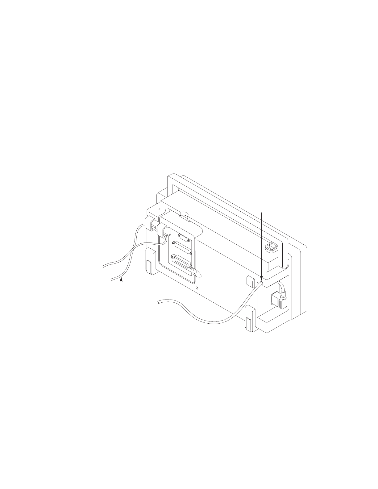
Power Cord
Use only power cords designed for your oscilloscope. Use a power
source that delivers 90 to 264 VAC
page 105 for a list of available power cords.
Use the power cord notch to help route the cord to the rear of the
instrument and avoid inadvertently disconnecting the power source.
, 45 to 440 Hz. Refer to
RMS
Power cord
notch
Getting Started
Securing cable
Security Loop
Use the built-in cable channels to secure both your instrument and
extension module to your location.
TDS 200-Series Digital Oscilloscope User Manual
3
Page 16
Getting Started
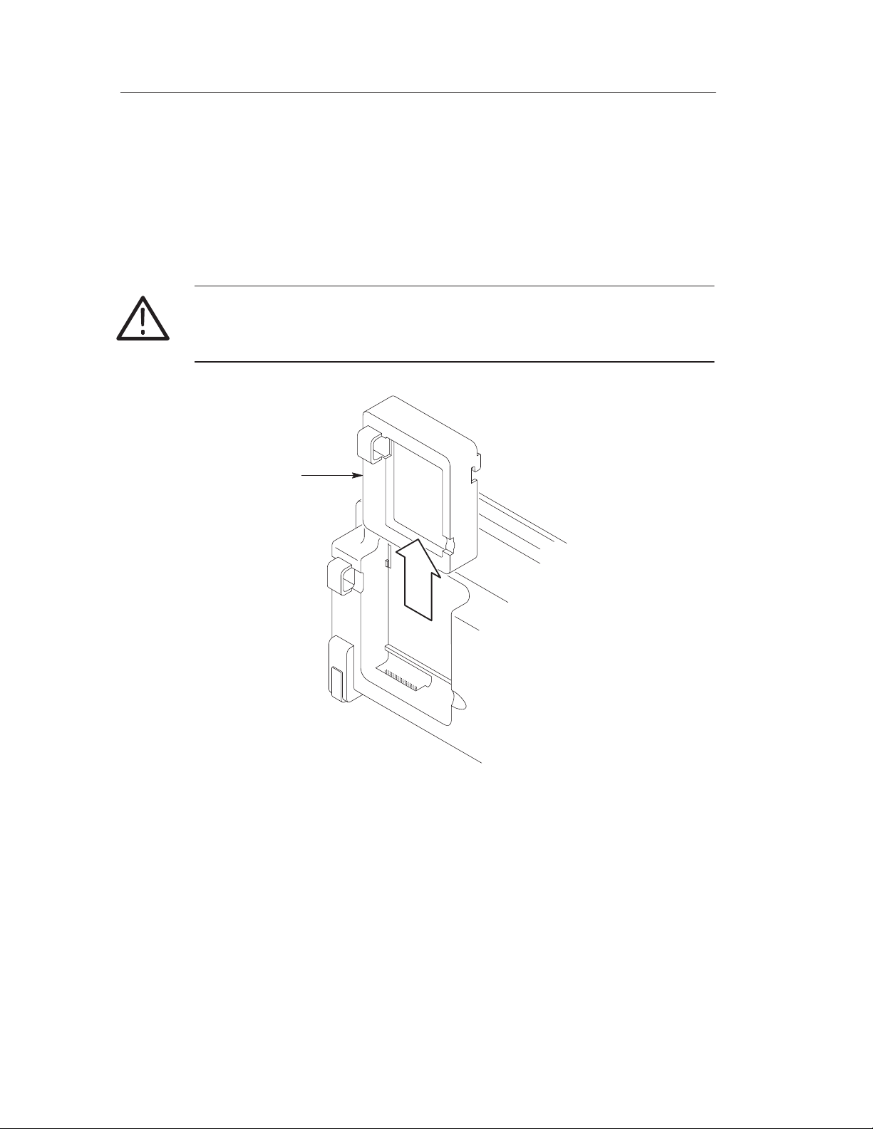
Extension Modules
You can increase the feature set of your oscilloscope by inserting an
extension module. Refer to page 103 for information about the
available modules.
CAUTION. Electr ostatic discharge (ESD) can damage components in
the extension module and the oscilloscope. Do not operate your
instrument with the extension module connector exposed.
Modules slide
in and out
4
TDS 200-Series Digital Oscilloscope User Manual
Page 17
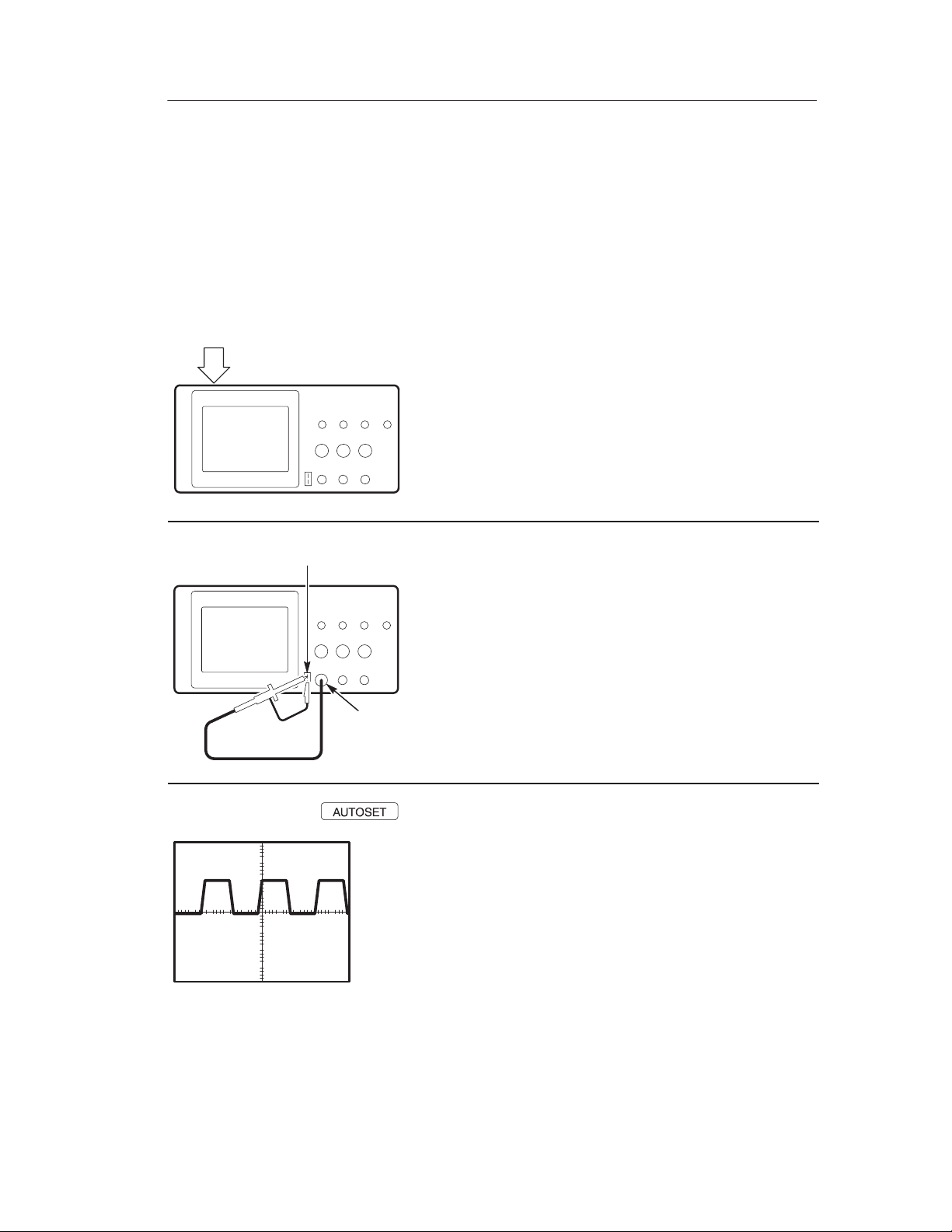
Functional Check
Perform this quick functional check to verify that your instrument is
operating correctly .
Getting Started
ON/OFF
button
PASSED
PROBE COMP
CH 1
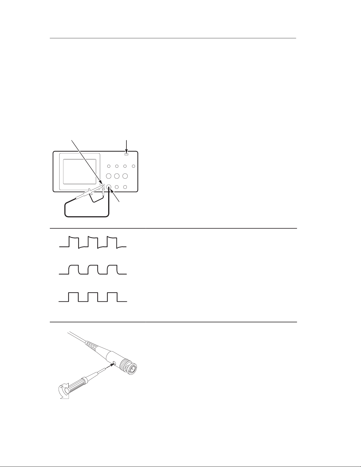
1. Turn on the instrument.
Wait until the display shows that all self
tests passed. Push the SAVE/RECALL
button, select Setups in the top menu box
and push the Recall Factory menu box.
The default Probe menu attenuation
setting is 10X.
2. Set the switch to 10X on the P2100 probe
and connect the probe to channel 1 on the
oscilloscope. To do this, align the slot in
the probe connector with the key on the
CH 1 BNC, push to connect, and twist to
the right to lock the probe in place.
Attach the probe tip and reference lead to
the PROBE COMP connectors.
3. Push the AUTOSET button. Within a few
seconds, you should see a square wave in
the display (approximately 5 V at 1 kHz
peak-to-peak).
Push the CH 1 MENU button twice to turn
off channel 1, push the CH 2 MENU
button to turn on channel 2, repeat steps 2
and 3. For TDS 224, repeat for CH 3 and
CH 4.
TDS 200-Series Digital Oscilloscope User Manual
5
Page 18
Getting Started
Probe Compensation
Perform this adjustment to match your probe to the input channel.
This should be done whenever you attach a probe for the first time to
any input channel.
PROBE
COMP
Overcompensated
Undercompensated
AUTOSET
button
CH 1
1. Set the Probe menu attenuation to 10X.
Set the switch to 10X on the P2100 probe
and connect the probe to channel 1 on the
oscilloscope. If you use the probe hooktip, ensure a proper connection by firmly
inserting the tip onto the probe.
Attach the probe tip to the PROBE COMP
5V connector and the reference lead to the
PROBE COMP Ground connector, turn on
the channel, and then press AUTOSET.
2. Check the shape of the displayed
waveform.
Compensated correctly
6
3. If necessary, adjust your probe.
Repeat as necessary .
TDS 200-Series Digital Oscilloscope User Manual
Page 19
Self Calibration
The self calibration routine lets you quickly optimize the oscilloscope signal path for maximum measurement accuracy. You can run
the routine at anytime but you should always run the routine if the
ambient temperature changes by 5_ C or more.
To compensate the signal path, disconnect any probes or cables from
the input connectors. Then, press the UTILITY button and select Do
Self Cal to confirm that you are ready to proceed.
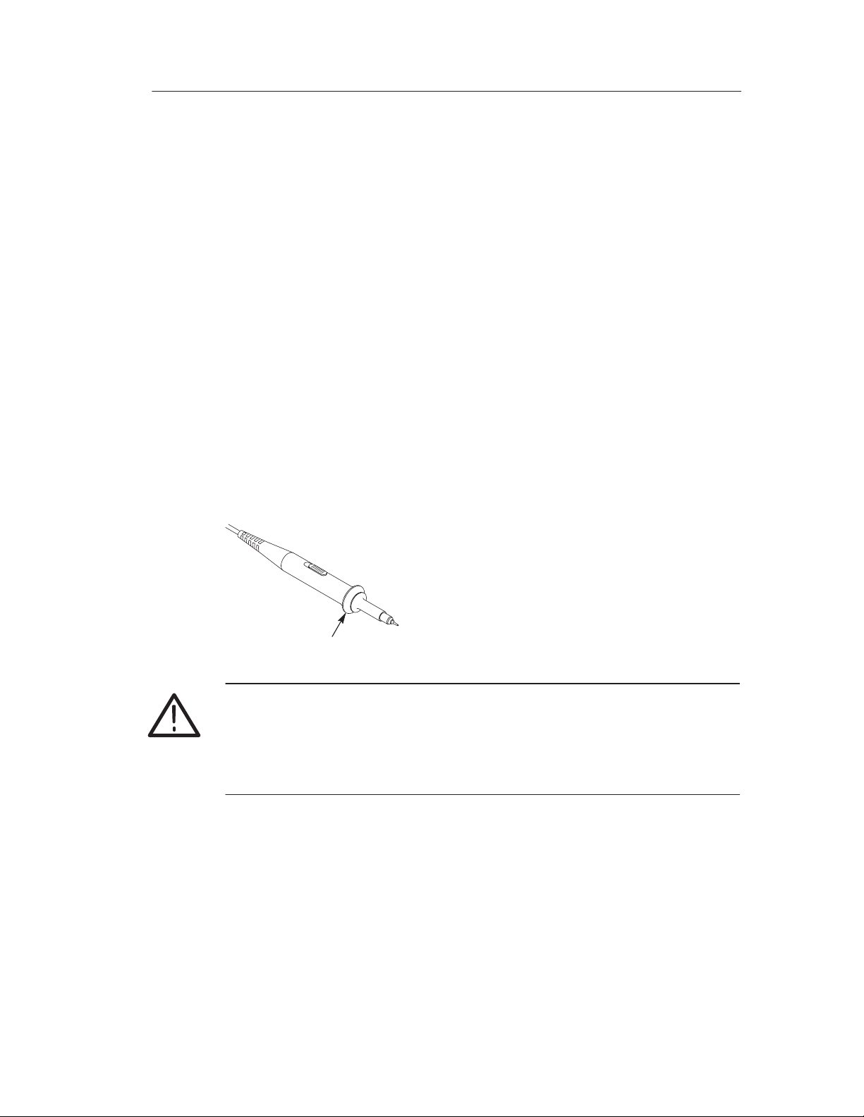
Probe Safety
A guard around the probe body provides a finger barrier for
protection from electric shock.
Getting Started
Finger guard
WARNING. To avoid electric shock when using the probe, keep fingers
behind the guard on the probe body.
To avoid electric shock while using the probe, do not touch metallic
portions of the probe head while it is connected to a voltage source.
Connect the probe to the instrument and connect the ground terminal
to ground before you take any measurements.
TDS 200-Series Digital Oscilloscope User Manual
7
Page 20

Getting Started
Probe Attenuation Setting
Probes are available with various attenuation factors which affect the
vertical scale of the signal.
To change (or check) the probe attenuation setting, press the
VERTICAL MENU button (of the channel you are using), and then
press the menu selection next to Probe until the correct setting is
displayed.
This setting remains in effect until changed again.
NOTE. The default Probe menu attenuation setting is 10X when the
oscilloscope is shipped.
Be sure that the Attenuation switch on the P2100 probe is set to
match the Probe menu selection in the oscilloscope. The probe
switch settings are 1X and 10X.
Attenuation switch
NOTE. When the Attenuation switch is set to 1X, the P2100 probe
limits the bandwidth of the oscilloscope to 7 MHz. To use the full
bandwidth of the oscilloscope, be sure to set the switch to 10X.
8
TDS 200-Series Digital Oscilloscope User Manual
Page 21
Basic Concepts
To use your oscilloscope effectively, you must understand the
following basic concepts:
H Triggering
H Acquiring data
H Scaling and positioning waveforms
H Measuring waveforms
H Setting Up the oscilloscope
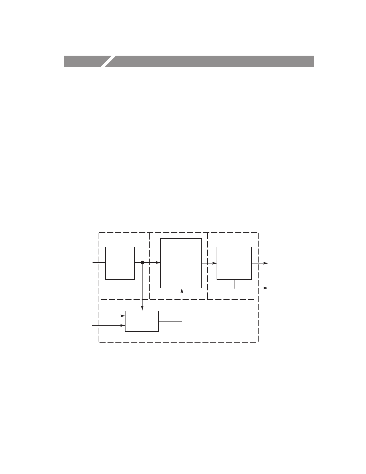
The figure below shows a block diagram of the various functions of
an oscilloscope and their relationship to each other .
Each
channel
Ext
AC Line
Vertical:
gain and
position
Trigger
Acquire data:
mode and
time base
Waveform
record:
2500 points
Display
Computer
interface
(TDS2CM)
TDS 200-Series Digital Oscilloscope User Manual
9
Page 22
Basic Concepts
Triggering
The trigger determines when the oscilloscope starts to acquire data
and display a waveform. When a trigger is set up properly, it can
convert unstable displays or blank screens into meaningful
waveforms.
Triggered waveform Untriggered waveforms
When the oscilloscope starts to acquire a waveform, it collects
enough data so that it can draw the waveform to the left of the
trigger point. The oscilloscope continues to acquire data while
waiting for the trigger condition to occur. After it detects a trigger,
the oscilloscope continues to acquire enough data so that it can draw
the waveform to the right of the trigger point.
Source
You can derive your trigger from various sources: Input channels,
AC Line, and External.
Input. The most commonly used trigger source is any one of the input
channels. The channel you select as a trigger source will function
whether it is displayed or not.
10
TDS 200-Series Digital Oscilloscope User Manual
Page 23

Basic Concepts
AC Line. You can use this trigger source when you want to look at
signals related to the power line frequency, such as lighting
equipment and power supply devices. The oscilloscope generates the
trigger, so you do not have to input a trigger signal.
External (TDS 210 and TDS 220 Only). You can use this trigger source
when you want to acquire data on two channels and trigger from a
third. For example, you might want to trigger from an external clock
or with a signal from another part of the test circuit.
The EXT and EXT/5 trigger sources both use the external trigger
signal connected to the EXT TRIG connector . EXT uses the signal
directly; you can use EXT on signals with a trigger level range of
+1.6 V to – 1.6 V.
The EXT/5 trigger source divides the signal by 5 which extends the
trigger level range from + 8 V to – 8 V. This allows the oscilloscope
to trigger on a larger signal.
Types
The oscilloscope provides two types of triggers: Edge and Video.
Edge. You can use the edge trigger with analog and digital test
circuits. An edge trigger occurs when the trigger input passes through
a specified voltage level in the specified direction.
Video. You can use the video trigger on fields or lines of standard
video signals. Refer to T riggering on a Video Signal on page 53.
Modes
The trigger mode determines how the oscilloscope behaves in the
absence of a trigger event. The oscilloscope provides three trigger
modes: Auto, Normal, and Single.
TDS 200-Series Digital Oscilloscope User Manual
11
Page 24

Basic Concepts
Auto. This trigger mode allows the oscilloscope to acquire a
waveform even when it does not detect a trigger condition. If no
trigger condition occurs while the oscilloscope waits for a specific
period (as determined by the time-base setting), it will force itself to
trigger.
Refer to T ime Base on page 16 for more information on time bases.
When forcing invalid triggers, the oscilloscope cannot synchronize
the waveform, and the waveform seems to roll across the display. If
valid triggers occur, the display becomes stable on the screen.
You can use Auto mode to monitor an amplitude level, such as a
power supply output, which may cause the waveform to roll across
the display .
Normal. The Normal mode allows the oscilloscope to acquire a
waveform only when it is triggered. If no trigger occurs, the
oscilloscope will not acquire a new waveform, and the previous
waveform, if any, will remain on the display.
Single. The Single mode allows the oscilloscope to acquire one
waveform each time you press the RUN button, and the trigger
condition is detected.
The data that the oscilloscope acquires depends on the acquisition
mode. Refer to Acquisition Modes on page 15 for more information
on the type of data each acquisition mode will acquire.
NOTE. When you use the Single trigger mode with the Average
acquisition mode, the number of waveforms specified in the number
of averages are acquired befor e the acquisition stops.
12
TDS 200-Series Digital Oscilloscope User Manual
Page 25
Basic Concepts
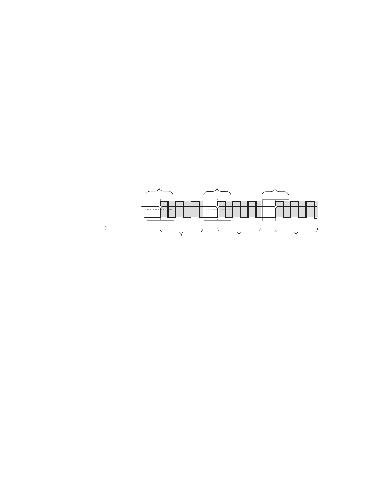
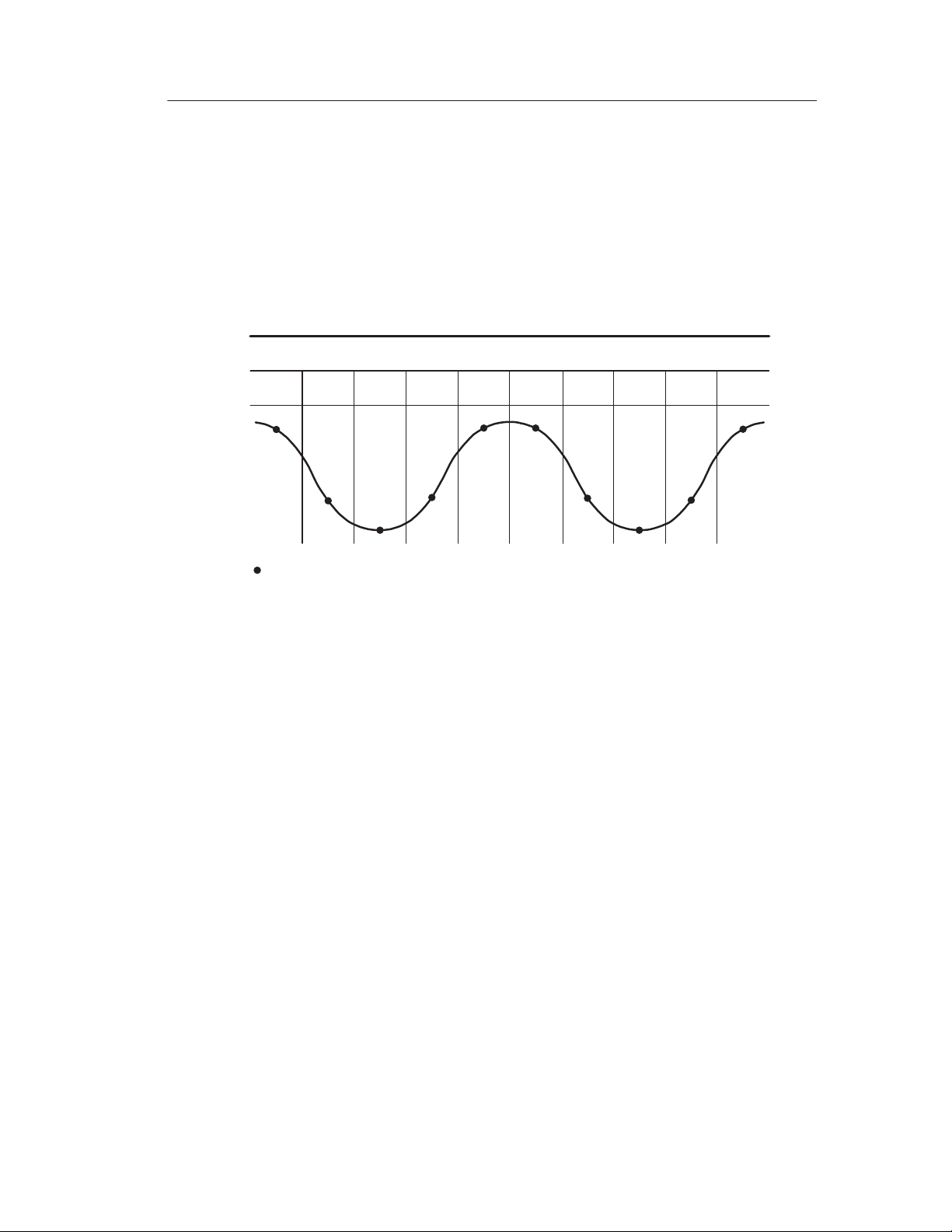
Holdoff
Triggers are not recognized during holdoff time (the period that
follows each acquisition). For some signals, you need to adjust the
holdoff period to produce a stable display.
The trigger signal can be a complex waveform with many possible
trigger points on it, such as a digital pulse train. Even though the
waveform is repetitive, a simple trigger might result in a series of
patterns on the screen instead of the same pattern each time.
Acquisition
interval
Trigger level
Indicates
trigger points
Holdoff
Triggers are not recognized during holdoff time.
Acquisition
interval
Holdoff
Holdoff
Acquisition
interval
Holdoff
For example, you could use the holdoff period to prevent triggering
on any other pulse except the first one in a pulse train. This way, the
oscilloscope would always display the first pulse.
To access the Holdoff control, press the HORIZONTAL Menu
button, select Holdoff, and use the HOLDOFF knob to change the
amount of time in the holdoff period.
TDS 200-Series Digital Oscilloscope User Manual
13
Page 26

Basic Concepts
Coupling
Trigger coupling determines what part of the signal passes on to the
trigger circuit. Coupling types include DC, AC, Noise Rejection,
High Frequency Rejection, and Low Frequency Rejection.
DC. DC coupling passes both AC and DC components.
AC. AC coupling blocks DC components.
Noise Rejection. Noise Reject coupling lowers the trigger sensitivity
and requires more signal amplitude for stable triggering. This
reduces the chance of falsely triggering on noise.
High Frequency Rejection. HF Reject coupling blocks the high
frequency portion and passes on only the low frequency components.
Low Frequency Rejection. LF Reject coupling does the opposite of high
frequency rejection.
Position
The horizontal position control establishes the time between the
trigger and the screen center. Refer to Horizontal Scale and Position;
Pretrigger Information on page 17 for more information on how to
use this control to position the trigger .
Slope and Level
The Slope and Level controls help to define the trigger.
The Slope control determines whether the oscilloscope finds the
trigger point on the rising or the falling edge of a signal. To access
the trigger slope control, press the TRIGGER Menu button, select
Edge, and use the Slope button to select Rising or Falling.
14
TDS 200-Series Digital Oscilloscope User Manual
Page 27

Basic Concepts
The Level control determines where on the edge the trigger point
occurs. To access the trigger level control, press the HORIZONTAL
Menu button, select Level, and use the LEVEL knob to change the
value.
Positive-going
edge
Trigger level can be
adjusted vertically
Trigger slope can be
positive or negative
Negative-going
edge
Acquiring Data
When you acquire analog data, the oscilloscope converts it into a
digital form. You can acquire data using three different acquisition
modes. The timebase setting affects how rapidly data is acquired.
Acquisition Modes
There are three acquisition modes: Sample, Peak Detect, and
Average.
Sample. In this acquisition mode, the oscilloscope samples the signal
in evenly spaced intervals to construct the waveform. This mode
accurately represents analog signals most of the time.
TDS 200-Series Digital Oscilloscope User Manual
15
Page 28

Basic Concepts
However, this mode does not acquire rapid variations in the analog
signal that may occur between samples. This can result in aliasing
(described on page 18) and may cause narrow pulses to be missed. In
these cases, you should use the Peak Detect mode to acquire data.
Peak Detect. In this acquisition mode, the oscilloscope finds the
highest and lowest values of the input signal over a sample interval
and uses these values to display the waveform. In this way, the
oscilloscope can acquire and display narrow pulses, which may have
otherwise been missed in Sample mode. Noise will appear to be
higher in this mode.
Average. In this acquisition mode, the oscilloscope acquires several
waveforms, averages them, and displays the resulting waveform. You
can use this mode to reduce random noise.
Time Base
The oscilloscope digitizes waveforms by acquiring the value of an
input signal at discrete points. The time base allows you to control
how often the values are digitized.
To adjust the time base to a horizontal scale that suits your purpose,
use the SEC/DIV knob.
Scaling and Positioning Waveforms
You can change the display of waveforms by adjusting their scale
and position. When you change the scale, the waveform display will
increase or decrease in size. When you change the position, the
waveform will move up, down, right, or left.
16
TDS 200-Series Digital Oscilloscope User Manual
Page 29

Basic Concepts
The channel reference indicator (located on the left of the graticule)
identifies each waveform on the display. The indicator points to the
ground level of the waveform record.
Vertical Scale and Position
You can change the vertical position of waveforms by moving them
up or down on the display. To compare data, you can align a
waveform above another or you can align waveforms on top of each
other.
You can change the vertical scale of a waveform. The waveform
display will contract or expand about the ground level.
Horizontal Scale and Position; Pretrigger Information
You can adjust the Horizontal Position control to view waveform
data before the trigger, after the trigger, or some of each. When you
change the horizontal position of a waveform, you are actually
changing the time between the trigger and the center of the display.
(This appears to move the waveform to the right or left on the
display.)
For example, if you want to find the cause of a glitch in your test
circuit, you might trigger on the glitch and make the pretrigger
period large enough to capture data before the glitch. You can then
analyze the pretrigger data and perhaps find the cause of the glitch.
You change the horizontal scale of all the waveforms by using the
SEC/DIV knob. For example, you might want to see just one cycle of
a waveform to measure the overshoot on its rising edge.
TDS 200-Series Digital Oscilloscope User Manual
17
Page 30
Basic Concepts
The oscilloscope shows the time per division in the scale readout.
Since all active waveforms use the same time base, the oscilloscope
only displays one value for all the active channels, except when you
use a Window Zone.
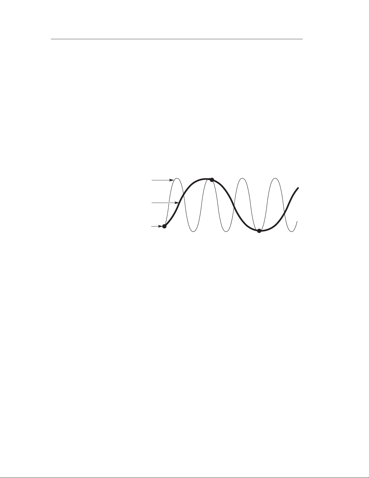
Aliasing. Aliasing occurs when the oscilloscope does not sample the
signal fast enough to construct an accurate waveform record. When
aliasing happens, you see a waveform with a frequency lower than
the actual waveform being input or a waveform that is not stable
even though the oscilloscope triggered.
Actual high-frequency
Apparent low-frequency
waveform due to aliasing
waveform
Sampled points
One way to check for aliasing is to slowly change the horizontal
scale with the SEC/DIV knob. If the shape of the waveform changes
drastically, you may have aliasing.
To represent a signal accurately and avoid aliasing, you must sample
the signal more than twice as fast as the highest frequency component. For example, a signal with frequency components of 5 MHz
would need to be sampled at 10 Megasamples per second or faster .
18
TDS 200-Series Digital Oscilloscope User Manual
Page 31

Basic Concepts
The next table lists the time bases that you should use to avoid
aliasing at various frequencies and the respective sample rate.
Samples
Time base
1.0 ms
2.5 ms
5.0 ms
10.0 ms
25.0 ms
50.0 ms
100.0 ms
250.0 ms
500.0 ms
1.0 ms 250.0 kS/s 125.0 kHz 5.0 s 50.0 S/s 25.0 Hz
2.5 ms 100.0 kS/s 50.0 kHz
* Bandwidth is not valid for the P2100 probe when the switch is set to 1X.
per second
250.0 MS/s 125.0 MHz* 5.0 ms 50.0 kS/s 25.0 kHz
100.0 MS/s 50.0 MHz* 10.0 ms 25.0 kS/s 12.5 kHz
50.0 MS/s 25.0 MHz* 25.0 ms 10.0 kS/s 5.0 kHz
25.0 MS/s 12.5 MHz* 50.0 ms 5.0 kS/s 2.5 kHz
10.0 MS/s 5.0 MHz* 100.0 ms 2.5 kS/s 1.25 kHz
5.0 MS/s 2.5 MHz 250.0 ms 1.0 kS/s 500.0 Hz
2.5 MS/s 1.25 MHz 500.0 ms 500.0 S/s 250.0 Hz
1.0 MS/s 500.0 kHz 1.0 s 250.0 S/s 125.0 Hz
500.0 kS/s 250.0 kHz 2.5 s 100.0 S/s 50.0 Hz
Maximum
frequency
Time base
Samples
per second
Maximum
frequency
There are various ways to prevent aliasing: adjust the horizontal
scale, push the AUTOSET button, or change the acquisition mode.
NOTE. If aliasing occurs, change to the Peak Detect acquisition
mode (described on page 16). This mode samples the highest and
lowest values so that the oscilloscope can detect faster signals.
TDS 200-Series Digital Oscilloscope User Manual
19
Page 32

Basic Concepts
Taking Measurements
The oscilloscope displays graphs of voltage versus time and can help
you to measure the displayed waveform.
There are several ways to take measurements. You can use the
graticule, the cursors, or an automated measurement.
Graticule
This method allows you to make a quick, visual estimate. For
example, you might look at a waveform amplitude and determine
that it is a little more than 100 mV.
You can take simple measurements by counting the major and minor
graticule divisions involved and multiplying by the scale factor .
For example, if you counted five major vertical graticule divisions
between the minimum and maximum values of a waveform and
knew you had a scale factor of 100 mV/division, then you could
easily calculate your peak-to-peak voltage as follows:
Cursor
Cursor
5 divisions x 100 mV/division = 500 mV.
20
TDS 200-Series Digital Oscilloscope User Manual
Page 33

Basic Concepts
Cursors
This method allows you to take measurements by moving the
cursors, which always appear in pairs, and reading their numeric
values from the display readouts. There are two types of cursors:
Voltage and Time.
When you use cursors, be sure to set the Source to the waveform that
you want to measure.
Voltage Cursors. Voltage cursors appear as horizontal lines on the
display and measure the vertical parameters.
Time Cursors. Time cursors appear as vertical lines on the display and
measure the horizontal parameters.
Automated
When you take automated measurements, the oscilloscope does all
the calculating for you. Because these measurements use the
waveform record points, they are more accurate than graticule or
cursor measurements.
Automated measurements use readouts to show measurement results.
These readouts are updated periodically as the oscilloscope acquires
new data.
Setting Up the Oscilloscope
You should become familiar with three functions that you will use
often when operating your oscilloscope: Autoset, saving a setup, and
recalling a setup. Included is a description of the default settings for
normal operation of the oscilloscope.
TDS 200-Series Digital Oscilloscope User Manual
21
Page 34

Basic Concepts
Using Autoset
The Autoset function obtains a stable waveform display for you. It
automatically adjusts the vertical and horizontal scaling, as well as
the trigger coupling, type, position, slope, level, and mode settings.
Saving a Setup
By default, the oscilloscope saves the setup each time it is powered
off. The oscilloscope automatically recalls this setup the next time it
is powered on.
NOTE. You should wait at least five seconds after your last change to
the setup before you turn off the power. This ensures that the setup is
saved properly.
You can also permanently save up to five setups in the memory of
the oscilloscope and overwrite setups as needed.
Recalling a Setup
The oscilloscope can recall any of the saved setups or the factory
default setup.
Defaults (Factory Setup)
The oscilloscope is set up for normal operation when it is shipped
from the factory. You can recall the factory default setup any time
you want to operate the oscilloscope using or starting from the
factory default settings.
22
TDS 200-Series Digital Oscilloscope User Manual
Page 35
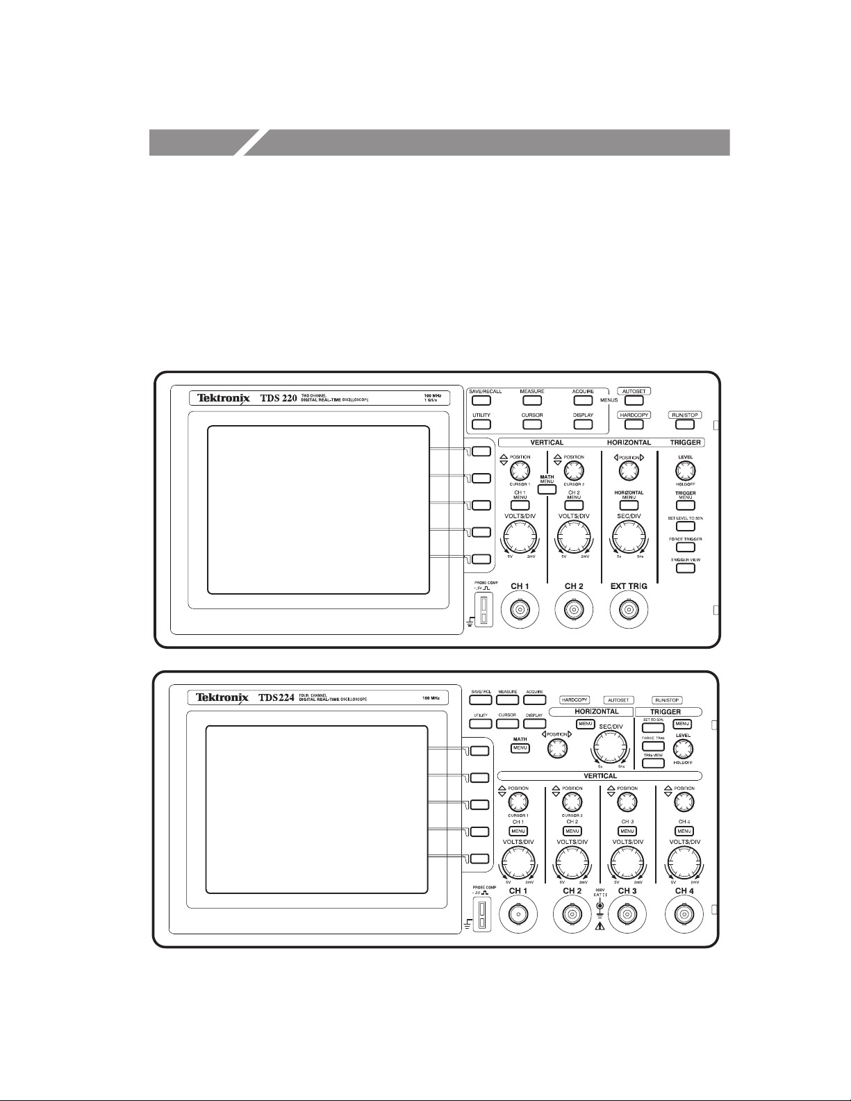
Operating Basics
The front panel is divided into easy to use functional areas. This
section provides you with a quick overview of the controls and the
information displayed on the screen. The next figure shows the front
panels for a TDS 210 or TDS 220, and for a TDS 224 oscilloscope.
TDS 200-Series Digital Oscilloscope User Manual
23
Page 36

Operating Basics
Display Area
In addition to displaying waveforms, the display is filled with many
details about the waveform and the instrument control settings.
13
12
Ch1 500mV
12 43
Trig'd
5
Pos:-11.30ms
750mVCh1W 100msM 500msCh2 200mV
24
67891011
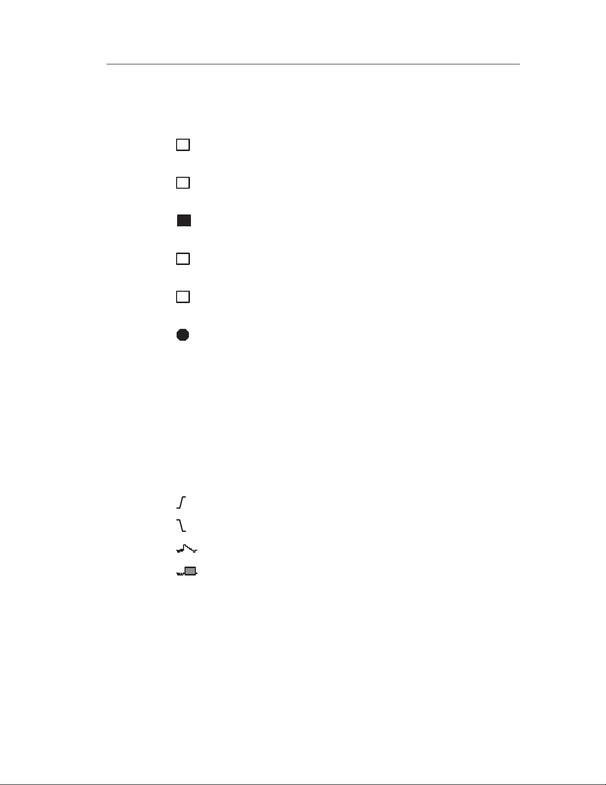
1. Icon display shows acquisition mode.
Sample mode
Peak detect mode
Average mode
TDS 200-Series Digital Oscilloscope User Manual
Page 37
2. Trigger status indicates the following:
g
Operating Basics
Armed.
triggers are ignored in this state.
R
Ready.
instrument is ready to accept a trigger .
T
Tri
posttrigger data.
R
Auto.
waveforms in the absence of triggers.
Scan.
data continuously in scan mode.
Stop.
3. Marker shows horizontal trigger position. This is adjusted by the
Horizontal Position control.
4. Readout shows the time difference between the center graticule
and horizontal trigger position. Center screen equals zero.
The instrument is acquiring pretrigger data. All
All pretrigger data has been acquired and the
'd.
The instrument has seen a trigger and is acquiring the
The instrument is in auto mode and is acquiring
The instrument is acquiring and displaying waveform
The instrument has stopped acquiring waveform data.
5. Marker shows trigger level.
6. Readout shows numeric value of the trigger level.
7. Icon shows selected trigger type as follows:
– Edge trigger for the rising edge.
– Edge trigger for the falling edge.
– Video trigger for line sync.
– Video trigger for field sync.
TDS 200-Series Digital Oscilloscope User Manual
25
Page 38

Operating Basics
8. Readout shows trigger source used for triggering.
9. Readout shows window time base setting if it is in use.
10.Readout shows main time base setting.
11. Readouts show the vertical scale factors of the channels.
12.Display area shows on-line messages momentarily .
13.On-screen markers show the ground reference points of the
displayed waveforms. No marker indicates the channel is not
displayed.
Using the Menu System
The user interface of the TDS 200-series oscilloscopes was designed
for easy access to specialized functions through the menu structure.
When you press a menu button on the front panel, the associated
menu title displays at the top right of the screen. There can be up to
five menu boxes below the menu title. To the right of each menu box
is a bezel button you can use to change the menu setting.
There are four types of menu boxes you can use to change settings:
Circular Lists, Action Buttons, Radio Buttons, and Page Selections.
Circular List Menu Boxes
A Circular List menu box appears with a title on top with the
selected choice listed below in reverse video. For example, you can
push the menu box button to cycle through the vertical coupling
choices in the CH1 Menu.
26
TDS 200-Series Digital Oscilloscope User Manual
Page 39

Operating Basics
Action Button Menu Boxes
An Action Button menu box displays the name of the action. For
example, you can use the two lowest menu boxes in the DISPLAY
menu to increase or decrease the contrast.
Radio Button Menu Boxes
Radio Button menu boxes are separated by dashed lines. The name
of the selected menu box displays in reverse video. For example, you
can use the top three menu boxes in the ACQUIRE menu to select an
acquisition mode.
Page Selection Menu Boxes
A Page Selection menu box contains two menus for a single button
on the front panel with the selected menu displayed in reverse video.
Each time you press the top menu box button to toggle between the
two menus, the menu boxes below also change.
For example, when you press the SAVE/RECALL front panel button,
the top Page Selection menu contains the names of two menus:
Setups and Waveforms. When you select the Setups menu, you can
use the remaining menu boxes to save or recall setups. When you
select the Waveforms menu, you can use the remaining menu boxes
to save or recall waveforms.
The SAVE/RECALL, MEASURE, and TRIGGER front panel
buttons display Page Selection menu boxes.
Action Button Radio ButtonCircular List
or
or
Page Selection
TDS 200-Series Digital Oscilloscope User Manual
27
Page 40
Operating Basics
Waveform Displays
Obtaining a waveform display is dependent on many instrument
settings. Once you obtain a waveform, you can take your measurements. But the appearance of these waveforms also provides key
information about the waveform.
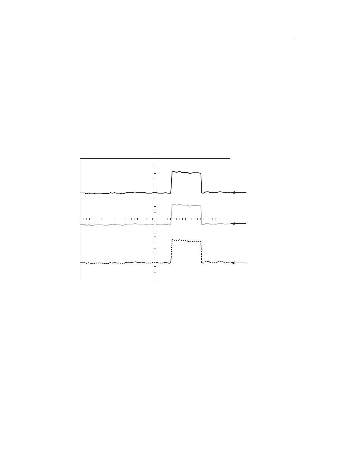
Depending on the type, waveforms will be displayed in three
different styles: black, gray, and broken.
1
2
3
1. A solid black waveform indicates a live waveform display. The
waveform remains black when the acquisition is stopped if no
controls are changed that make the display accuracy uncertain.
Changing the vertical and horizontal controls is allowed on
stopped acquisitions.
28
TDS 200-Series Digital Oscilloscope User Manual
Page 41

2. Reference waveforms and waveforms with persistence applied
appear gray.
3. A broken line appearance indicates the waveform display
accuracy is uncertain. This is the result of stopping the acquisition and then changing a control setting that the instrument
cannot modify the displayed waveform to match. For example,
changing the trigger controls on a stopped acquisition causes a
broken-line waveform.
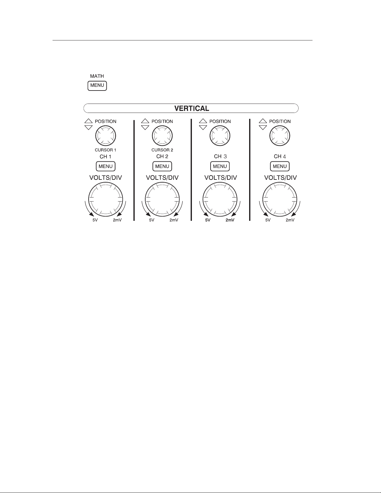
Vertical Controls
Operating Basics
TDS 210 and TDS 220
TDS 200-Series Digital Oscilloscope User Manual
29
Page 42
Operating Basics
TDS 224
CH 1, 2, 3 & 4 and CURSOR 1 & 2 POSITION. Positions the waveform
vertically. When cursors are turned on and the cursor menu is
displayed, these knobs position the cursors.
CH 1, CH 2, CH 3 & CH 4 MENU. Displays the channel input menu
selections and toggles the channel display on and off.
VOLTS/DIV (CH1, CH 2, CH 3 & CH 4). Selects calibrated scale factors.
MATH MENU. Displays waveform math operations menu and can also
be used to toggle the math waveform on and off.
30
TDS 200-Series Digital Oscilloscope User Manual
Page 43

Horizontal Controls
Operating Basics
TDS 224
TDS 210 and TDS 220
POSITION. Adjusts the horizontal position of all channels and math
waveforms. The resolution of this control varies with the time base.
NOTE. To make a large adjustment to the horizontal position, change
the SEC/DIV to 50 ms, change the horizontal position, and then
change the SEC/DIV back to the previous value.
HORIZONTAL MENU. Displays the horizontal menu.
TDS 200-Series Digital Oscilloscope User Manual
31
Page 44

Operating Basics
SEC/DIV. Selects the horizontal time/div (scale factor) for the main or
the window time base. When Window Zone is enabled, it changes
the width of the window zone by changing the window time base.
Refer to page 75 for details about creating and using the Window
Zone.
Trigger Controls
TDS 224
TDS 210 and TDS 220
LEVEL and HOLDOFF. This control has a dual purpose. As an edge
trigger level control, it sets the amplitude level the signal must cross
to cause an acquisition. As a holdoff control, it sets the amount of
time before another trigger event can be accepted. Refer to Holdoff
on page 13 for more information.
32
TDS 200-Series Digital Oscilloscope User Manual
Page 45
TRIGGER MENU. Displays the trigger menu.
SET LEVEL TO 50%. The trigger level is set to the vertical midpoint
between the peaks of the trigger signal.
FORCE TRIGGER. Starts an acquisition regardless of an adequate
trigger signal. This button has no effect if the acquisition is already
stopped.
TRIGGER VIEW. Displays the trigger waveform in place of the channel
waveform while the TRIGGER VIEW button is held down. You can
use this to see how the trigger settings affect the trigger signal, such
as trigger coupling.
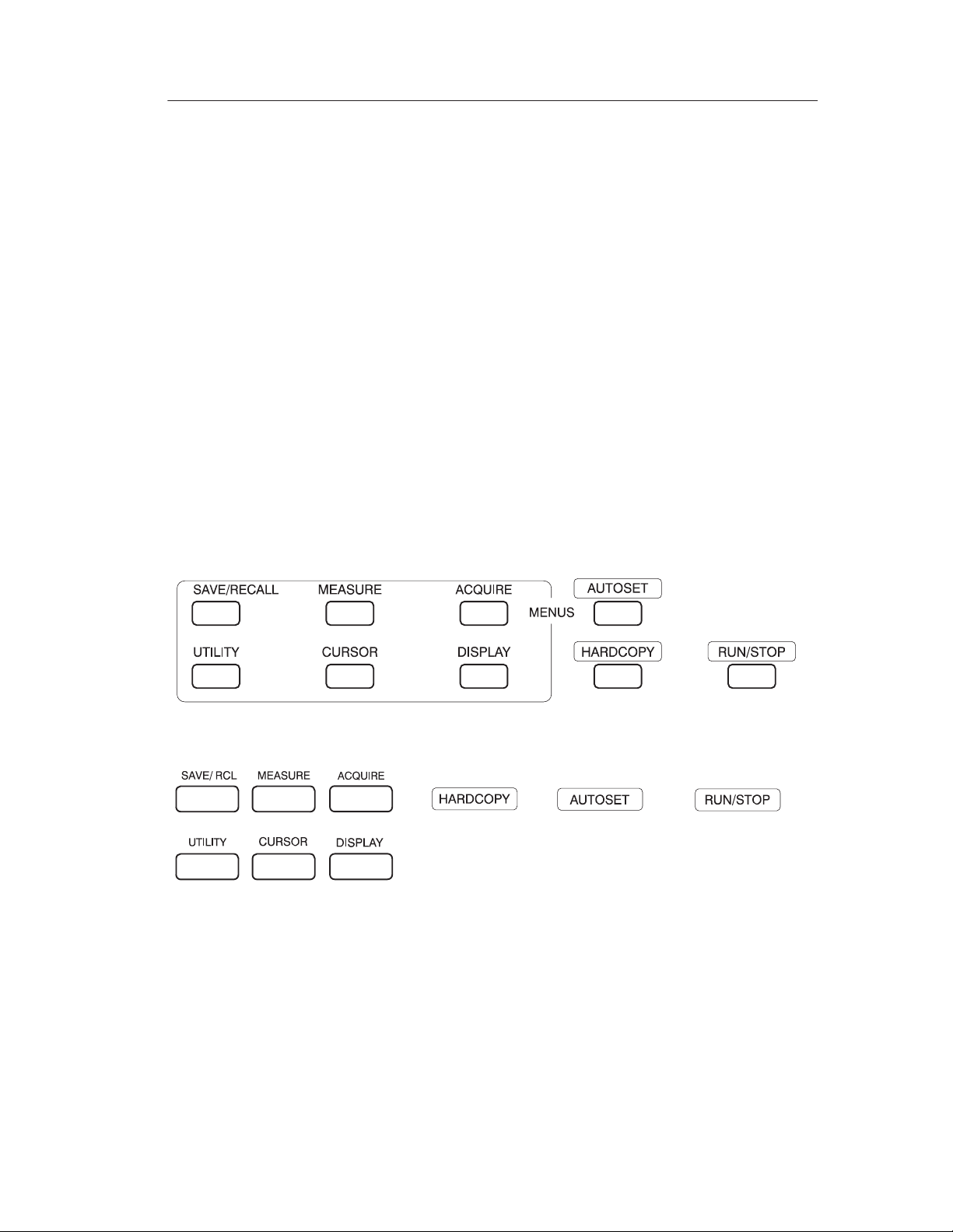
Menu and Control Buttons
Operating Basics
TDS 210 and TDS 220
TDS 224
TDS 200-Series Digital Oscilloscope User Manual
33
Page 46

Operating Basics
SAVE/RECALL. Displays the save/recall menu for setups and
waveforms.
MEASURE. Displays the automated measurements menu.
ACQUIRE. Displays the acquisition menu.
DISPLAY. Displays the display menu.
CURSOR. Displays the cursor menu. Vertical Position controls adjust
cursor position while displaying the cursor menu and the cursors are
turned on. Cursors remain displayed (unless turned off) after leaving
the cursor menu but are not adjustable.
UTILITY. Displays the utility menus.
AUTOSET. Automatically sets the instrument controls to produce a
usable display of the input signal.
HARDCOPY. Starts print operations. An extension module with a
Centronics, RS-232, or GPIB port is required. Refer to Optional
Accessories on page 103.
RUN/STOP. Starts and stops waveform acquisition.
34
TDS 200-Series Digital Oscilloscope User Manual
Page 47
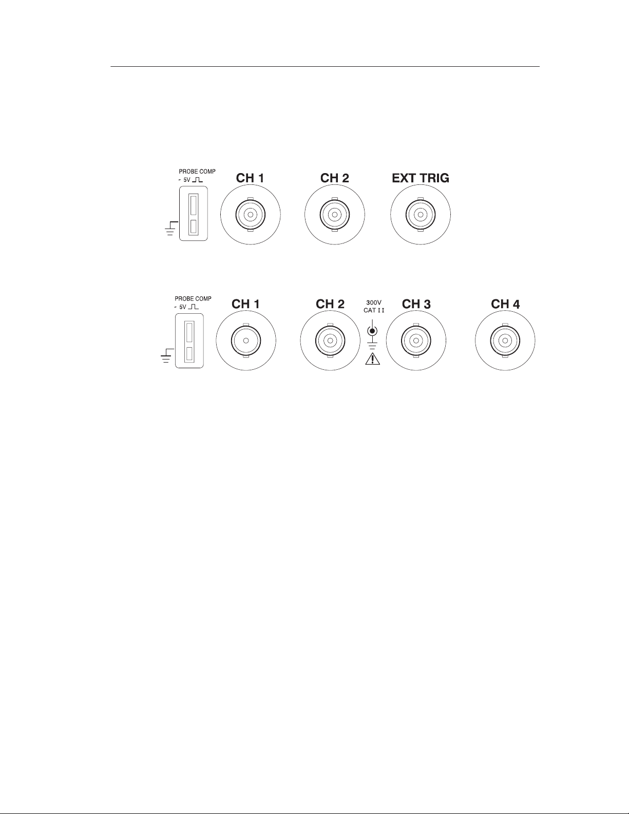
Connectors
TDS 210 and TDS 220
Operating Basics
TDS 224
PROBE COMP. Voltage probe compensation output and ground. Use
this to electrically match the probe to the input circuit. Refer to
page 6.
The probe compensation ground and BNC shields are connected to
earth ground. Do not connect a voltage source to these ground
terminals.
CH 1, CH 2, CH 3 & CH 4. Input connectors for waveform display.
EXT TRIG. Input connector for an external trigger source. Use the
trigger menu to select the trigger source.
TDS 200-Series Digital Oscilloscope User Manual
35
Page 48

Operating Basics
36
TDS 200-Series Digital Oscilloscope User Manual
Page 49

Application Examples
This section presents a series of application examples. These
simplified examples highlight the features of the oscilloscope and
give you ideas for using it to solve your own test problems.
H T aking simple measurements
Using Autoset
Using the Measure menu to take automatic measurements
Measuring two signals and calculating gain
H Taking cursor measurements
Measuring pulse width
Measuring rise time
Measuring ring frequency and ring amplitude
H Analyzing signal detail
Looking at a noisy signal
Using the average function to separate a signal from noise
H Triggering on a video signal
Triggering on video fields and video lines
Using the window function to see waveform details
Triggering on odd or even video fields
H Analyzing a differential communication signal
Using math functions
H Viewing impedance changes in a network
Using XY mode
Using persistence
TDS 200-Series Digital Oscilloscope User Manual
37
Page 50

Application Examples
Taking Simple Measurements
You need to see a signal in a circuit, but you do not know the
amplitude or frequency of the signal. You want to quickly display the
signal and measure the frequency, period, and peak-to-peak
amplitude.
CH 1
Using Autoset
To quickly display a signal, do these steps:
1. Set the Probe menu attenuation to 10X. Set the switch to 10X on
the P2100 probe.
2. Connect the channel 1 probe to the signal.
3. Push the AUTOSET button.
The oscilloscope sets the vertical, horizontal, and trigger controls
automatically. If you want to optimize the display of the waveform,
you can manually adjust these controls.
When you use more than one channel, the autoset function sets the
vertical controls for each channel and uses the lowest-numbered
active channel to set the horizontal and trigger controls.
38
TDS 200-Series Digital Oscilloscope User Manual
Page 51
Application Examples
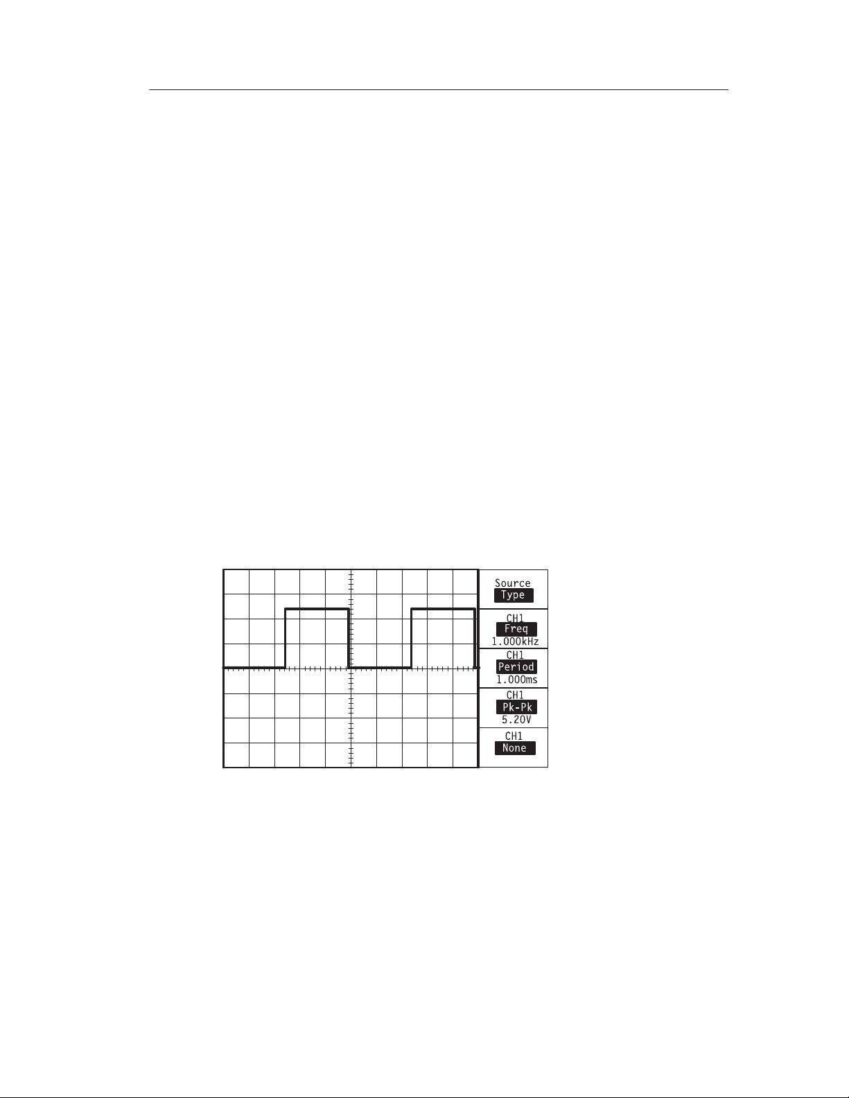
T aking Automatic Measurements
The oscilloscope can take automatic measurements of most
displayed signals. To measure signal frequency, period, and
peak-to-peak amplitude, do these steps:
1. Push the MEASURE button to see the Measure menu.
2. Push the top menu box button to select Source.
3. Select CH1 for the first three measurements.
4. Push the top menu box button to select Type.
5. Push the first CH1 menu box button to select Freq.
6. Push the second CH1 menu box button to select Period.
7. Push the third CH1 menu box button to select Pk-Pk.
The frequency, period, and peak-to-peak measurements are shown in
the menu and are updated periodically.
TDS 200-Series Digital Oscilloscope User Manual
39
Page 52

Application Examples
Measuring Two Signals
You are testing a piece of equipment and need to measure the gain of
the audio amplifier . You have an audio generator that can inject a test
signal at the amplifier input. Connect two oscilloscope channels to
the amplifier input and output as shown. Measure both signal levels
and use the measurements to calculate the gain.
CH 1 CH 2
40
TDS 200-Series Digital Oscilloscope User Manual
Page 53

Application Examples
To activate and display the signals connected to channel 1 and to
channel 2, do these steps:
1. If the channels are not displayed, push the CH 1 MENU and then
CH 2 MENU buttons.
2. Push the AUTOSET button.
To select measurements for the two channels, do these steps:
1. Select the source channels.
a. Push the MEASURE button to see the Measure menu.
b. Push the top menu box button to select Source.
c. Push the second menu box button to select CH1.
d. Push the third menu box button to select CH2.
2. Select the type of measurement displayed for each channel.
a. Push the top menu box button to select Type.
b. Push the CH1 menu box button to select Pk-Pk.
c. Push the CH2 menu box button to select Pk-Pk.
3. Read the peak-to-peak amplitudes for channel 1 and channel 2 in
the menu display.
4. Calculate the amplifier gain using the following equations:
Gain +
Gain (dB) + 20 log(Gain)
output amplitude
input amplitude
TDS 200-Series Digital Oscilloscope User Manual
41
Page 54

Application Examples
Taking Cursor Measurements
You can use the cursors to quickly take time and voltage measurements on a waveform.
Measuring Pulse Width
You are analyzing a pulse waveform, and you want to know the
width of the pulse. To measure the width of a pulse using the time
cursors, do these steps:
1. Push the CURSOR button to see the Cursor menu.
2. Push the top menu box button to select Time.
3. Push the Source menu box button to select CH1.
4. Use the CURSOR 1 knob to place a cursor on the rising edge of
the pulse.
5. Use the CURSOR 2 knob to place the remaining cursor on the
falling edge of the pulse.
You can see the following measurements in the Cursor menu:
H The time at Cursor 1, relative to the trigger.
H The time at Cursor 2, relative to the trigger.
H The delta time, which is the pulse width measurement.
42
TDS 200-Series Digital Oscilloscope User Manual
Page 55

Application Examples
NOTE. The TDS2MM extension module provides pulse width as an
automatic measurement.
Measuring Rise Time
After measuring the pulse width, you decide that you need to check
the rise time of the pulse. Typically, you measure rise time between
the 10% and 90% portion of the waveform. To measure the rise time,
do these steps:
1. Adjust the SEC/DIV knob to display the rising edge of the
waveform.
2. Adjust the VOLTS/DIV knob to set the waveform amplitude to
about five divisions.
3. Push the CH 1 MENU button to see the CH1 menu if it is not
displayed.
4. Push the Volts/Div button to select Fine.
TDS 200-Series Digital Oscilloscope User Manual
43
Page 56

Application Examples
5. Adjust the VOLTS/DIV knob to set the waveform amplitude to
exactly five divisions.
6. Use the VERTICAL POSITION knob to center the waveform;
position the baseline of the waveform 2.5 divisions below the
center graticule.
7. Push the CURSOR button to see the Cursor menu.
8. Push the top menu box button to set the type to Time.
9. Use the CURSOR 1 knob to place the cursor at the point where
the waveform crosses the second graticule line below center
screen. This is the 10% point on the waveform.
10.Use the CURSOR 2 knob to place the second cursor at the point
where the waveform crosses the second graticule line above
center screen. This is the 90% point on the waveform.
5 divisions
11. The delta readout in the cursor menu is the rise time of the
waveform.
NOTE. The TDS2MM extension module provides rise time as an
automatic measurement.
44
TDS 200-Series Digital Oscilloscope User Manual
Page 57

Application Examples
Measuring Ring Frequency
To measure the ring frequency at the rising edge of a signal, do these
steps:
1. Push the CURSOR button to see the Cursor menu.
2. Push the top menu box button to select Time.
3. Use the CURSOR 1 knob to place a cursor on the first peak of
the ring.
4. Use the CURSOR 2 knob to place a cursor on the second peak of
the ring.
You can see the delta time and frequency (the measured ring
frequency) in the Cursor menu.
TDS 200-Series Digital Oscilloscope User Manual
45
Page 58

Application Examples
Measuring Ring Amplitude
You measured the ring frequency in the previous example. Now you
want to measure the amplitude of the ringing. To measure the
amplitude, do these steps:
1. Push the CURSOR button to see the Cursor menu.
2. Push the top menu box button to select Voltage.
3. Use the CURSOR 1 knob to place a cursor on the highest peak of
the ring.
4. Use the CURSOR 2 knob to place a cursor on the lowest point of
the ring.
You can see the following measurements in the cursor menu:
H The delta voltage (peak-to-peak voltage of the ringing)
H The voltage at Cursor 1
H The voltage at Cursor 2
46
TDS 200-Series Digital Oscilloscope User Manual
Page 59

Analyzing Signal Detail
You have a noisy signal displayed on the oscilloscope and you need
to know more about it. You suspect that the signal contains much
more detail than you can now see in the display.
Application Examples
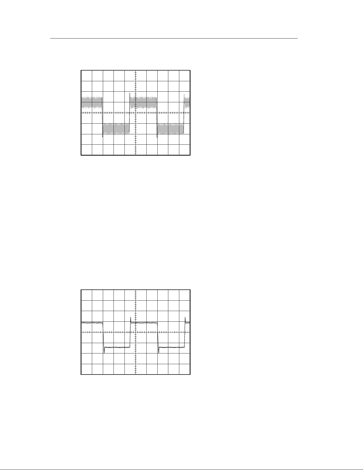
Looking at a Noisy Signal
The signal appears noisy and you suspect that noise is causing
problems in your circuit. To better analyze the noise, do these steps:
1. Push the ACQUIRE button to see the Acquire menu.
2. Push the Peak detect button.
3. If necessary, push the DISPLAY button to see the Display menu.
Use the Contrast Increase and Contrast Decrease menu box
buttons to adjust the contrast to see the noise more easily.
Peak detect emphasizes noise spikes and glitches in your signal,
especially when the time base is set to a slow setting.
TDS 200-Series Digital Oscilloscope User Manual
47
Page 60
Application Examples
Separating the Signal from Noise
Now you want to analyze the signal shape and ignore the noise. To
reduce random noise in the oscilloscope display, do these steps:
1. Push the ACQUIRE button to see the Acquire menu.
2. Push the Average menu box button.
3. Push the Averages menu box button to see the effects of varying
the number of running averages on the waveform display.
Averaging reduces random noise and makes it easier to see detail in a
signal. In the example below, a ring shows on the rising and falling
edges of the signal when the noise is removed.
48
TDS 200-Series Digital Oscilloscope User Manual
Page 61
Capturing a Single-Shot Signal
The reliability of a reed relay in a piece of equipment has been poor
and you need to investigate the problem. You suspect that the relay
contacts arc when the relay opens. The fastest you can open and
close the relay is about once per minute so you need to capture the
voltage across the relay as a single-shot acquisition.
To set up for a single-shot acquisition, do these steps:
1. Adjust the vertical VOLTS/DIV and horizontal SEC/DIV to
appropriate ranges for the signal you expect to see.
2. Push the ACQUIRE button to see the Acquire menu.
3. Push the Peak detect button.
4. Push the TRIGGER MENU button to see the Trigger menu.
Application Examples
5. Push the Mode button to select Single (single sequence).
6. Push the Slope button to select Rising.
7. Use the LEVEL knob to adjust the trigger level to a voltage
midway between the open and closed voltages of the relay.
8. If the readout at the top of the screen does not display Armed or
Ready, then push the RUN/STOP button to start the acquisition.
When the relay opens, the oscilloscope is triggered and captures the
event.
TDS 200-Series Digital Oscilloscope User Manual
49
Page 62

Application Examples
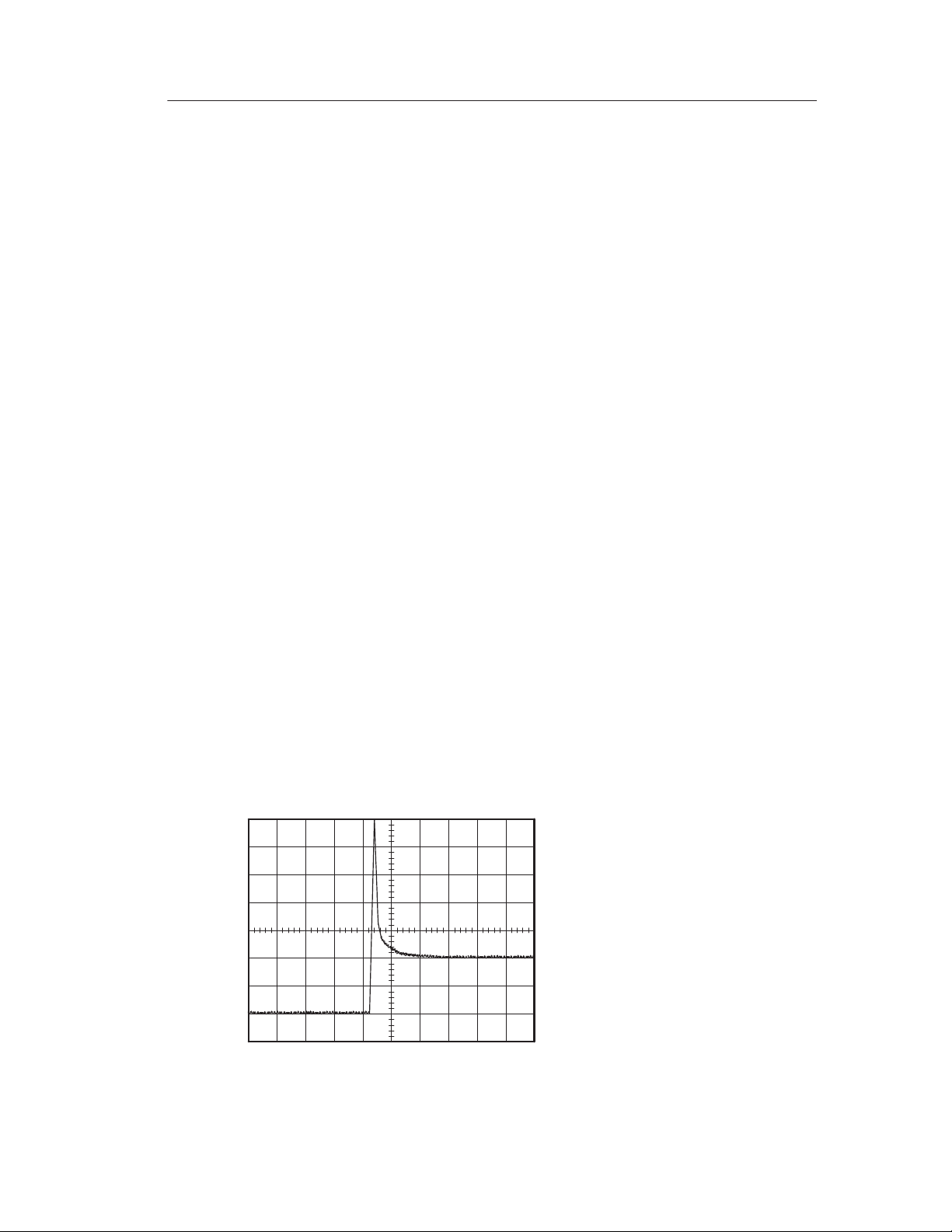
Optimizing the Acquisition
The initial acquisition shows the relay contact beginning to open at
the trigger point. This is followed by a large spike that indicates
contact bounce and inductance in the circuit. The inductance can
cause contact arcing and premature relay failure.
You can adjust the vertical, horizontal, and trigger controls to
optimize the settings before the next single-shot event is captured.
When the next acquisition is captured with the new settings, you can
see more detail about the relay contact opening. You can now see
that the contact bounces several times as it opens.
50
TDS 200-Series Digital Oscilloscope User Manual
Page 63
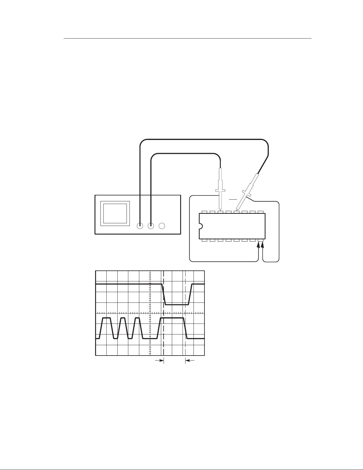
Measuring Propagation Delay
You suspect that the memory timing in a microprocessor circuit is
marginal. Set up the oscilloscope to measure the propagation delay
between the chip-select signal and the data output of the memory
device.
Application Examples
Data CS
CH 1 CH 2
TDS 200-Series Digital Oscilloscope User Manual
51
Page 64

Application Examples
To set up to measure propagation delay, do these steps:
1. If the channels are not displayed, push the CH 1 MENU and then
CH 2 MENU buttons.
2. Push AUTOSET to trigger a stable display.
3. Adjust the horizontal and vertical controls to optimize the
display.
4. Push the CURSOR button to see the Cursor menu.
5. Push the top menu box button to select Time.
6. Push the Source menu box button to select CH1.
7. Use the CURSOR 1 knob to place the cursor on the active edge
of the chip-select signal.
8. Use the CURSOR 2 knob to place the second cursor on the data
output transition.
9. Read the propagation delay in the Delta readout in the cursor
menu.
52
TDS 200-Series Digital Oscilloscope User Manual
Page 65
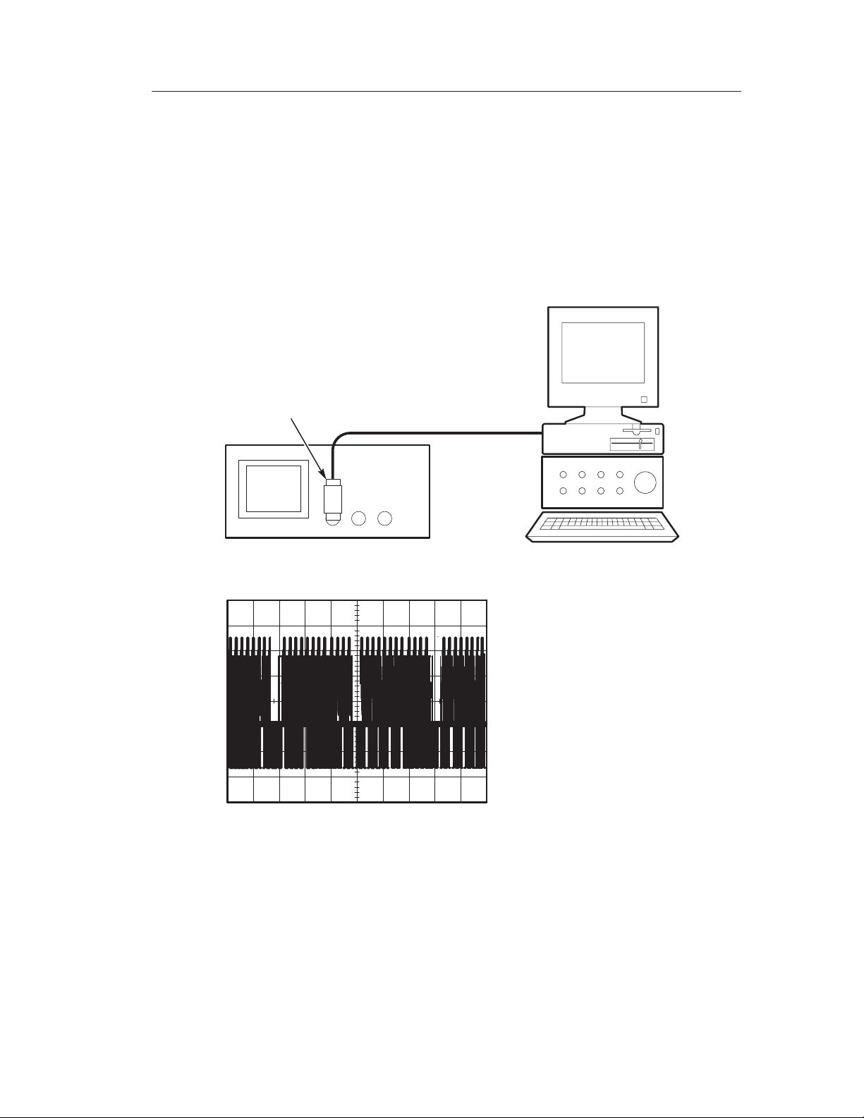
Triggering on a Video Signal
You are testing the video circuit in a piece of medical equipment and
need to display the video output signal. The video output is an NTSC
standard signal. Use the video trigger to obtain a stable display.
75 W terminator
Application Examples
CH 1
TDS 200-Series Digital Oscilloscope User Manual
53
Page 66

Application Examples
Triggering on Video Fields
To trigger on the video fields, do these steps:
1. Push the TRIGGER MENU button to see the Trigger menu.
2. Push the top menu box button to select Video.
3. Push the Sync menu box button to select Field.
4. Adjust the horizontal SEC/DIV knob to see a complete field
across the screen.
5. Push the HORIZONTAL MENU button to see the Main menu.
6. Push the Trig knob menu box button to select Holdoff.
7. Adjust the HOLDOFF knob to an appropriate period. You can
use about 21 ms for NTSC (and PAL) video.
Triggering on Video Lines
You can also look at the video lines in the field. To trigger on the
lines, do these steps:
1. Push the TRIGGER MENU button to see the Trigger menu.
2. Push the top menu box button to select Video.
3. Push the Sync menu box button to select Line.
4. Adjust the horizontal SEC/DIV knob to see a complete video line
across the screen.
54
TDS 200-Series Digital Oscilloscope User Manual
Page 67

75 W terminator
CH 1
Application Examples
Incoming video signal
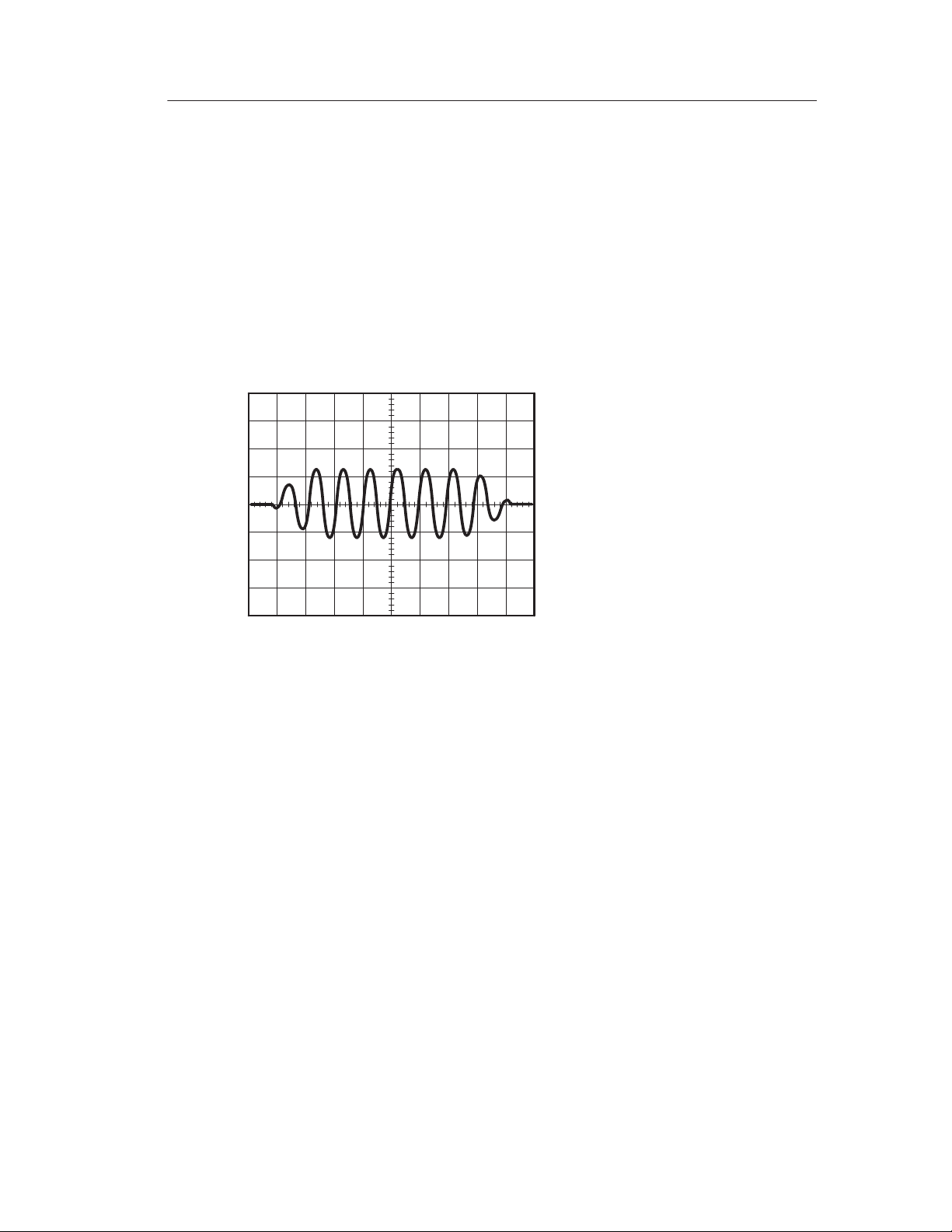
Using the Window Function to See Waveform Details
You can use the window function to examine a specific portion of a
waveform without changing the main display.
TDS 200-Series Digital Oscilloscope User Manual
55
Page 68

Application Examples
If you want to view the color burst in the previous waveform in more
detail without changing the main display, do these steps:
1. Push the HORIZONTAL MENU button to see the Horizontal
menu and select Main.
2. Adjust the horizontal SEC/DIV knob to select 50 ms.
3. Push the Trig knob menu box button to select Holdoff.
4. Adjust the HOLDOFF knob to 61 ms.
5. Adjust the horizontal SEC/DIV knob until you see a whole line.
6. Push the Window Zone menu box button.
7. Adjust the SEC/DIV knob to set the width of the window (area to
be expanded).
8. Adjust the HORIZONTAL POSITION knob to position the
window around the portion of the waveform you want to expand.
56
TDS 200-Series Digital Oscilloscope User Manual
Page 69
Application Examples
9. Push the Window button to see the expanded portion of the
waveform.
10.Adjust the SEC/DIV knob to optimize viewing the expanded
waveform.
To switch between the Main and Window views, push the Main
or Window menu box button in the HORIZONTAL MENU.
Triggering on Odd or Even Video Fields
Your oscilloscope will trigger on both odd and even video fields, and
make the data difficult to view because the line details are a half line
apart. To remedy this, you can set the holdoff period to lock on just
the odd or even field, which produces a stable display.
For example, the field rate for NTSC video is 60 Hz. For stable
triggering, you should set the holdoff period to at least the field rate
(16.7 ms), but not to more than twice the field rate (33 ms).
TDS 200-Series Digital Oscilloscope User Manual
57
Page 70

Application Examples
To trigger on only an odd or even video field, do these steps:
1. If channel 1 is not displayed, push the CH 1 MENU button.
2. Use the VERTICAL POSITION knob to place the waveform on
the middle graticule line (position 0).
3. Adjust the VERTICAL VOLTS/DIV knob to 500 mV.
4. Push the Coupling menu box button to select DC.
5. Push the Probe menu box button to select 1X.
6. Push the TRIGGER MENU button to see the Trigger menu.
7. Push the top menu box button to select VIDEO.
8. Push the Polarity menu box button to select Normal.
9. Push the Source menu box button to select CH1.
10.Push the Sync menu box button to select Field.
11. Push the ACQUIRE button to see the Acquire menu.
12.Set SEC/DIV to 10 ms.
13.Adjust the HORIZONTAL POSITION knob to about 1.5 ms.
14.Push the HORIZONTAL MENU button to see the Main menu.
58
TDS 200-Series Digital Oscilloscope User Manual
Page 71

Application Examples
15.Push the Trig knob menu box button to select Holdoff.
16.Adjust the HOLDOFF knob to 21 ms for NTSC and PAL video.
NOTE. To make a large adjustment to the holdoff period, adjust the
SEC/DIV knob to 50 ms, adjust the HOLDOFF knob to 21 ms, and
readjust the SEC/DIV back to the previous value.
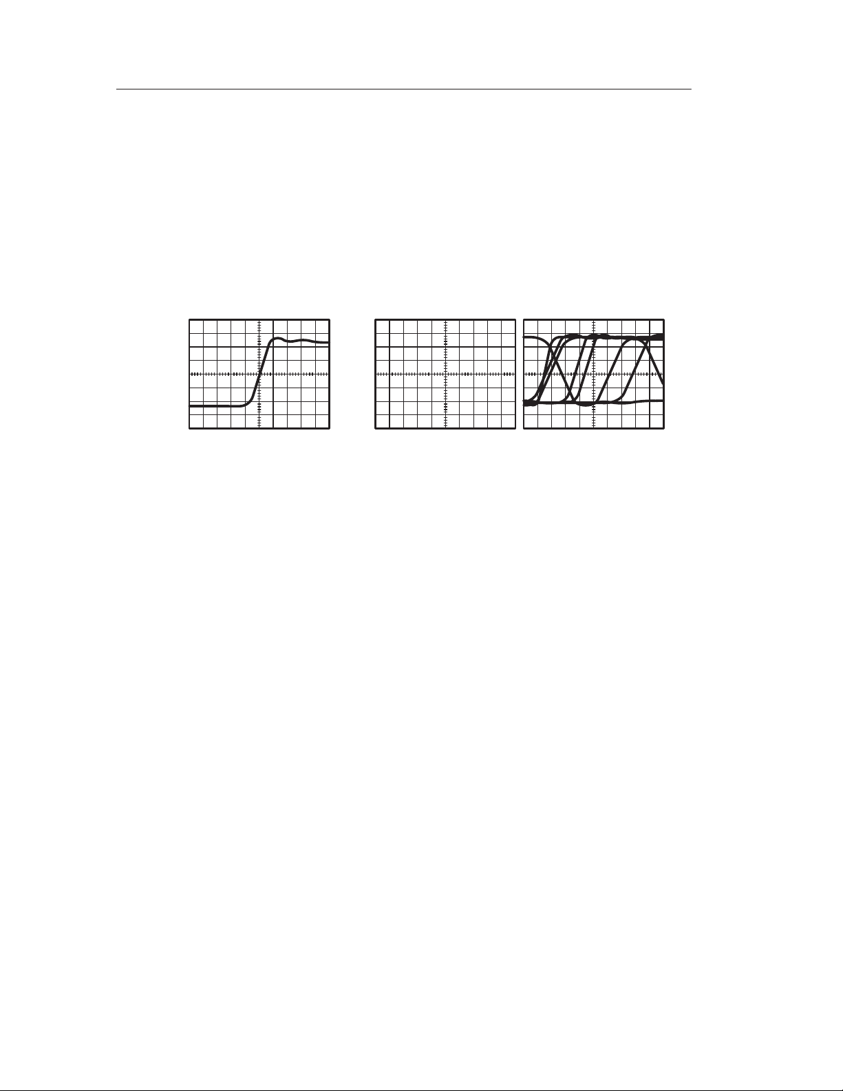
Now the oscilloscope only triggers on an odd or an even field (but
not both), and the line information is stable.
With 500 ns of holdoff time, you cannot
see any line information because the
alternating fields overlap
With 21 ms of holdoff time you can
easily see one clear line
TDS 200-Series Digital Oscilloscope User Manual
59
Page 72
Application Examples
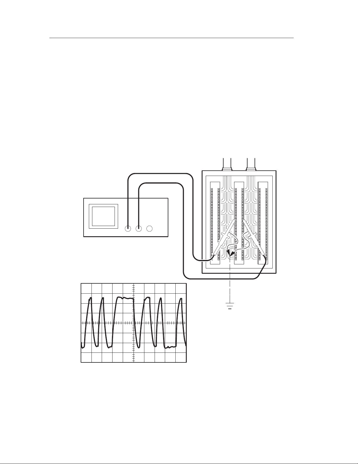
Analyzing a Differential Communication Signal
You are having intermittent problems with a serial data communication link, and you suspect poor signal quality. Set up the oscilloscope
to show you a snapshot of the serial data stream so you can verify the
signal levels and transition times.
Because this is a differential signal, you use the math function of the
oscilloscope to view a better representation of the waveform.
CH 1 CH 2
60
TDS 200-Series Digital Oscilloscope User Manual
Page 73

Application Examples
To activate the differential signals connected to channel 1 and
channel 2, do these steps:
1. Set the Probe menu attenuation to 10X. Set the switch to 10X on
the P2100 probes.
2. If the channels are not displayed, push the CH 1 MENU and then
CH 2 MENU buttons.
3. Push the AUTOSET button.
4. Push the MATH button to see the Math menu.
TDS 210 and TDS 220 (Firmware V 2.00 and Above), and TDS 224 (All Versions) Oscilloscopes
Do these steps:
1. Push the Operation menu box button to select –.
2. Push the CH1–CH2 menu box button to display a new waveform
that is the difference between the displayed waveforms.
For a more stable display, use the Run/Stop button to control the
acquisition of the waveform. Each time you push the Run/Stop
button, the instrument acquires a snapshot of the digital data stream.
You can use the cursors or automatic measurements to analyze the
waveform, or you can store the waveform to analyze later .
NOTE. Vertical sensitivity should match on waveforms used for math
operations. If they do not match, and you use cursors to measure the
waveform result, an U displays that represents unknown in the level
and delta readouts.
TDS 200-Series Digital Oscilloscope User Manual
61
Page 74

Application Examples
TDS 210 and TDS 220 Oscilloscopes (Firmware Below V 2.00) without a TDS2MM
Press the CH1–CH2 menu box button to display a new waveform
that is the difference between the displayed waveforms.
TDS 210 and TDS 220 Oscilloscopes (Firmware Below V 2.00) with a TDS2MM
Do these steps:
1. Push the CH2 MENU button and then push the CH2 Inverted
menu box button to invert the signal on channel 2.
2. Push the MATH MENU button and then push the CH1+CH2
menu box button to display a new waveform that is the difference
between the displayed waveforms.
62
TDS 200-Series Digital Oscilloscope User Manual
Page 75

Viewing Impedance Changes in a Network
You have designed a circuit that needs to operate over a wide
temperature range. You need to evaluate the change in impedance of
the circuit as the ambient temperature is changed.
Connect the oscilloscope to monitor the input and output of the
circuit and capture the changes that occur as you vary the temperature.
Circuit
Application Examples
CH 1 CH 2
In Out
TDS 200-Series Digital Oscilloscope User Manual
63
Page 76

Application Examples
To view the input and output of the circuit in an x-y display, do these
steps:
1. Set the Probe menu attenuation to 10X. Set the switch to 10X on
the P2100 probes.
2. Connect the channel 1 probe to the input of the network, and
connect the channel 2 probe to the output.
3. If the channels are not displayed, push the CH 1 MENU and
CH 2 MENU buttons.
4. Push the AUTOSET button.
5. Adjust the VOLTS/DIV knobs to display approximately the same
amplitude signals on each channel.
6. Push the DISPLAY button to see the Display menu.
7. Push the Format menu box button to select XY.
The oscilloscope displays a Lissajous pattern representing the
input and output characteristics of the circuit.
8. Adjust the VOLTS/DIV and VERTICAL POSITION knobs to
display a desirable waveform.
9. Push the Persist menu box button to select Infinite.
10.Push the Contrast Increase or Decrease menu box buttons to
adjust the contrast of the display for optimal viewing.
As you adjust the ambient temperature, the display persistence
captures the changes in the characteristics of the circuit.
64
TDS 200-Series Digital Oscilloscope User Manual
Page 77

Reference
This section describes the menus and operating details associated with
each front-panel menu button.
Reference Topic Page
Acquire 66
Autoset 70
Cursor 71
Display 72
Hard copy 90
Horizontal controls 74
Math 76
Measure 79
Save/Recall 81
Trigger controls 83
Utility 87
Vertical controls 89
TDS 200-Series Digital Oscilloscope User Manual
65
Page 78
Reference
Acquire
Push the ACQUIRE button to set acquisition parameters.
Menus Settings Comments
Sample This is the default mode
Peak Detect Use to detect glitches and reduce the
possibility of aliasing
Average Use to reduce random or uncorrelated
noise in the signal display. The number of
averages is selectable.
Averages 4
16
64
128
Select Number of Averages
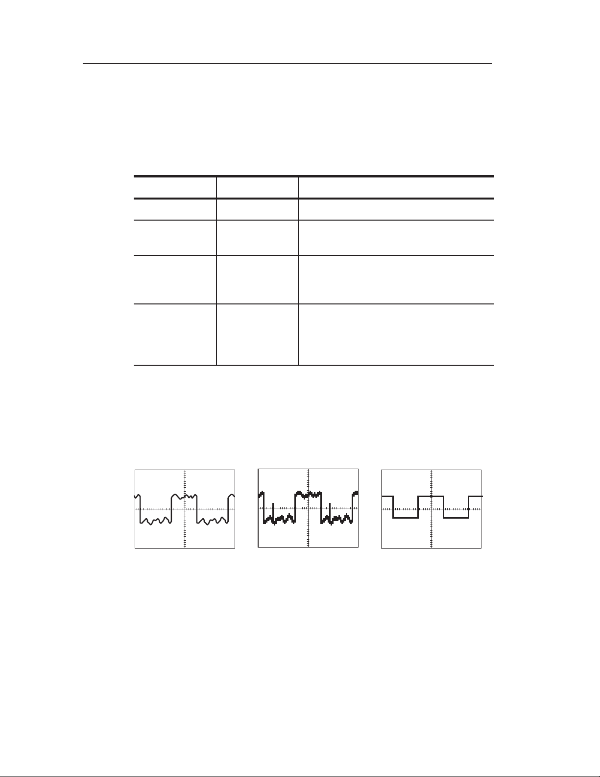
Key Points
If you probe a noisy square wave signal that contains intermittent,
narrow glitches, the waveform displayed will vary depending on the
acquisition mode you choose.
Sample Peak Detect Average
66
TDS 200-Series Digital Oscilloscope User Manual
Page 79
Reference
The next two topics describe each of the types of acquisition modes
and their differences.
Sample. Use Sample acquisition mode to acquire 2,500 points and
display them at the SEC/DIV setting. Sample mode is the default
mode.
Sample acquisition intervals (2500)
12345678910
Sample points
Sample mode acquires a single sample point in each interval.
The maximum sample rate is 1 GS/s. At 100 ns and faster settings,
this sample rate does not acquire 2,500 points. In this case, a Digital
Signal Processor interpolates points between the sampled points to
make a full 2,500 point waveform record.
Peak Detect. Use Peak Detect acquisition mode to detect glitches as
narrow as 10 ns and to limit the possibility of aliasing. This mode is
effective when at 5 ms/div or slower.
TDS 200-Series Digital Oscilloscope User Manual
67
Page 80
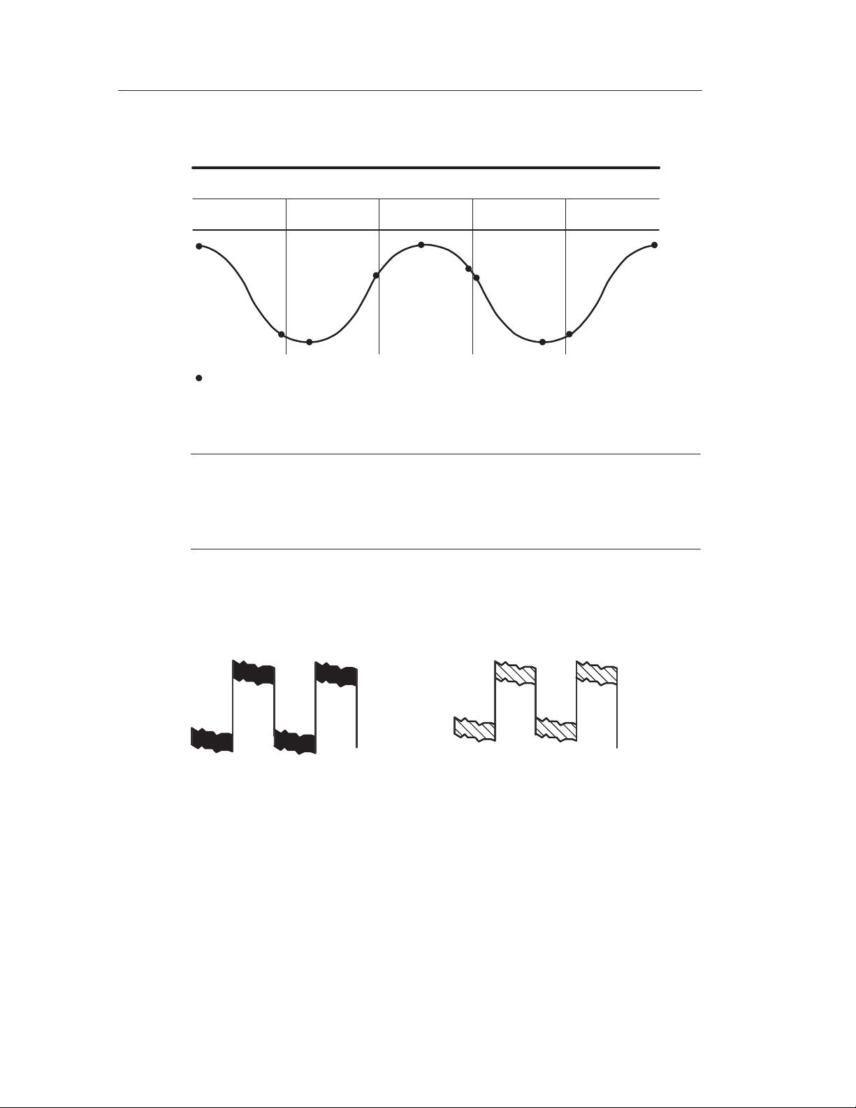
Reference
Sample acquisition intervals (1250)
12 345
Sample points displayed
Peak Detect mode displays highest and lowest acquired voltage in each
interval.
NOTE. If you set the SEC/DIV to 2.5 ms/div or faster, the acquisition
mode changes to Sample because the sample rate is fast enough that
you do not need to use Peak Detect. No message displays to tell you
that the mode was changed from Peak Detect to Sample.
When there is enough waveform noise, a typical peak detect display
shows large black areas. The TDS 200-series oscilloscopes displays
this area with diagonal lines to improve display performance.
Typical peak detect display
TDS 200 peak detect display
68
TDS 200-Series Digital Oscilloscope User Manual
Page 81

Reference
Average. Use Average acquisition mode to reduce random or
uncorrelated noise in the signal you want to display. Data is acquired
in sample mode, then a number of waveforms are averaged together .
Select the number of acquisitions (4, 16, 64, or 128) to average for
the waveform.
Scan Mode Display. When the SEC/DIV control is set to 100 ms/div or
slower and the trigger mode set to Auto, the instrument enters the
scan acquisition mode. In this mode, the waveform display updates
from left to right. There is no horizontal position or trigger control of
waveforms during scan mode.
Stopping the Acquisition. While acquisition is running, the waveform
display is live. Stopping the acquisition freezes the display. In either
mode, the waveform display can be scaled or positioned with the
vertical and horizontal controls.
TDS 200-Series Digital Oscilloscope User Manual
69
Page 82

Reference
Autoset
The Autoset feature automatically adjusts the controls to produce a
usable display of the input signal.
Pushing AUTOSET adjusts or sets each of the following items listed.
Function Setting
Acquire mode Adjusted to Sample or Peak Detect
Vertical coupling DC (if GND was selected)
Vertical VOLTS/DIV Adjusted
Bandwidth Full
Horizontal position Centered
Horizontal SEC/DIV Adjusted
Trigger type Edge
Trigger source Lowest numbered channel displayed
Trigger coupling Adjusted to DC, Noise Reject, or
HF Reject
Trigger slope Rising
Trigger holdoff Minimum
Trigger level Set to 50%
Display format YT
Trigger mode Auto
70
TDS 200-Series Digital Oscilloscope User Manual
Page 83

Cursors
Reference
Push the CURSOR button to display the measurement cursors and
cursor menu.
Menu Settings Comments
Type
Source CH1
Delta The difference (delta) between the cursors
Cursor 1 Displays cursor 1 location (time is
Cursor 2 Displays cursor 2 location (time is
Voltage
Time
Off
CH2
CH3*
CH4*
MATH
REFA
REFB
REFC*
REFD*
Select and display the measurement
cursors; Voltage measures amplitude and
Time measures time and frequency
Choose the waveform on which to take
the cursor measurement
The readouts display this measurement.
is displayed here
referenced to the trigger position, voltage
is referenced to ground)
referenced to the trigger position, voltage
is referenced to ground)
* Only available on the TDS 224 oscilloscope.
Key Points
Cursor Movement. Use the CH 1 and CH 2 Vertical Position knobs to
move cursors 1 and 2. You can move the cursors only while the
Cursor menu is displayed.
TDS 200-Series Digital Oscilloscope User Manual
71
Page 84
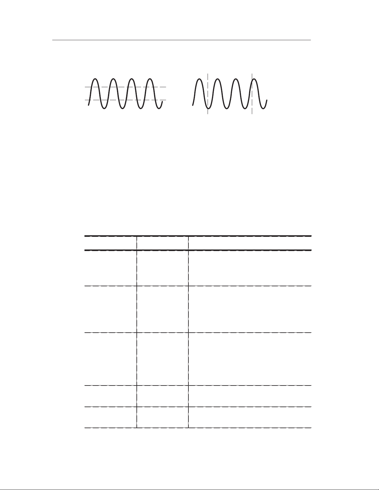
Reference
Display
Voltage cursors
U in Level and Delta Readouts. Vertical sensitivity should match on
Time cursors
waveforms used for math operations. If they do not match, and you
use cursors to measure the waveform result of a math operation, an U
displays that represents unknown.
Push the DISPLAY button to choose how waveforms are presented
and to change the appearance of the entire display.
Menu Settings Comments
Type Vectors
Dots
Persist OFF
1 sec
2 sec
5 sec
Infinite
Vectors fills the space between adjacent
sample points in the display
Dots displays only the sample points
Sets the length of time each displayed
sample point remains displayed
72
Format YT
XY
Contrast
Increase
Contrast
Decrease
YT format displays the vertical voltage in
relation to time (horizontal scale)
XY format displays channel 1 in the
horizontal axis and channel 2 in the
vertical axis
Darkens the black (or gray) areas of the
display
Lightens the white areas of the display
TDS 200-Series Digital Oscilloscope User Manual
Page 85

Reference
Key Points
Persistence. When using persistence, old data retained is displayed in
gray while the new data is black.
With Persistence set to Infinite, record points accumulate until a
control is changed.
XY Format. This format only applies to channels 1 and 2. Choose XY
display format to display channel 1 in the horizontal axis and channel
2 in the vertical axis. The oscilloscope uses the untriggered sample
acquisition mode and data displays as dots. The sampling rate is
1 MS/s and can not be changed.
NOTE. The oscilloscope can capture a waveform in normal YT mode
at any sampling rate. You can view the same waveform in XY mode.
To do so, stop the acquisition and change the display format to XY.
The controls operate as follows:
H The channel 1 VOLTS/DIV and vertical POSITION controls set
the horizontal scale and position.
H The channel 2 VOLTS/DIV and vertical POSITION controls
continue to set vertical scale and position.
The following functions do not work in XY display format:
H Ref or Math waveforms
H Cursors
H Autoset (resets display format to YT)
H Time base controls
H Trigger controls
TDS 200-Series Digital Oscilloscope User Manual
73
Page 86

Reference
Horizontal
You can use the horizontal controls to change the horizontal scale
and position of waveforms. The horizontal center of the screen is the
time reference for waveforms. Changing the horizontal scale causes
the waveform to expand or contract around the screen center .
Horizontal position changes the point, relative to the trigger, where
the waveform appears on the center of the screen.
Menu Settings Comments
Main The main horizontal time base setting is
used to display the waveform
Window
Zone
Window Changes the display to show the wave-
Trig knob Level
Holdoff
Two cursors define a window zone
Adjust the window zone with the Horizon-
tal Position and SEC/DIV controls
form segment (expanded to screen width)
within the window zone
Selects whether the Trigger Level knob
adjusts the trigger level (volts) or holdoff
time (sec)
The holdoff value is displayed
NOTE. You can push the Window menu box button to switch between
an entire waveform display and an enlarged, mor e detailed part of it.
74
TDS 200-Series Digital Oscilloscope User Manual
Page 87

Reference
Key Points
SEC/DIV. If waveform acquisition is stopped (using the RUN/STOP
button), the SEC/DIV control expands or compresses the waveform.
Scan Mode Display. When the SEC/DIV control is set to 100 ms/div or
slower and the trigger mode is set to Auto, the instrument enters the
scan acquisition mode. In this mode, the waveform display updates
from left to right. There is no trigger or horizontal control of
waveforms during scan mode.
Window Zone. Use the window zone to expand a segment of a
waveform to see more detail. The Window time base setting cannot
be set slower than the Main time base setting.
Vertical bars define window zone
Main
time base
displayed
Holdoff. Use holdoff to help stabilize the display of nonperiodic
Window zone
displayed
waveforms.
Holdoff begins when the instrument recognizes a trigger event and
disables the trigger system until acquisition is complete. The trigger
system remains disabled during the holdoff time that follows each
recognized trigger event.
TDS 200-Series Digital Oscilloscope User Manual
75
Page 88

Reference
Math
Although you access the Math menu in the same way, the menu
boxes vary, depending on the oscilloscope model, firmware version,
and installed module.
Push the MATH MENU button to display the waveform math
operations. Push the MATH MENU button again to turn off the math
waveform display. Refer to page 89 for vertical system descriptions.
The following tables list menu boxes available based on the
oscilloscope model, firmware version, and installed module.
TDS 210 and TDS 220 (Firmware V 2.00 and Above), and TDS 224 (All Versions) Oscilloscopes
Operation
menu
–
(subtraction)
+
(addition)
* Only available on the TDS 224 oscilloscope.
Menu Settings Comments
CH1 – CH2 The channel 2 waveform is sub-
tracted from the channel 1 waveform
CH2 – CH1 The channel 1 waveform is sub-
tracted from the channel 2 waveform
CH3 – CH4* The channel 4 waveform is sub-
tracted from the channel 3 waveform
CH4 – CH3* The channel 3 waveform is sub-
tracted from the channel 4 waveform
CH1 + CH2 Channels 1 and 2 are added together
CH3 + CH4*
Channels 3 and 4 are added together
NOTE. The optional TDS2MM measurement extension module adds
the FFT feature to the oscilloscope. See the TDS 200–Series
Extension Modules Instructions Manual.
76
TDS 200-Series Digital Oscilloscope User Manual
Page 89

Reference
TDS 210 and TDS 220 Oscilloscopes (Firmware Below V 2.00) without a TDS2MM
Menu Settings Comments
CH1 – CH2 The channel 2 waveform is subtracted
from the channel 1 waveform
CH2 – CH1 The channel 1 waveform is subtracted
from the channel 2 waveform
CH1 + CH2 Channels 1 and 2 are added together
CH1
Inverted
CH2
Inverted
The channel 1 signal display is inverted
(cannot be inverted if channel 2 is
inverted)
The channel 2 signal display is inverted
(cannot be inverted if channel 1 is
inverted)
TDS 210 and TDS 220 Oscilloscopes (Firmware Below V 2.00) with a TDS2MM
The TDS2MM Module when used with a TDS 210 or TDS 220
changes the following math operations:
H The TDS2MM Module does not have the CH1–CH2 and
CH2–CH1 math functions. To do the same functions, invert the
channel you want to subtract (using the CH1 or CH2 menu) and
then select the CH1+CH2 math function.
TDS 200-Series Digital Oscilloscope User Manual
77
Page 90

Reference
Default channel
subtraction
CH1–CH2 CH1+(–CH2) (–CH2) means invert channel 2
CH2–CH1 (–CH1)+CH2 (–CH1) means invert channel 1
TDS2MM channel
subtraction
Comments
H The TDS2MM Module moves the channel invert function from
the MATH menu to the Vertical CH1 and CH2 menus.
Key Points
VOLTS/DIV. Use the VOLTS/DIV control to scale the waveforms of
the channels. The math waveform is the visual sum or difference of
the channel waveforms.
Channel Display for a TDS 210 or TDS 220 (Firmware Below V 2.00).
Displaying a math waveform automatically removes the display of
channels used to create the math waveform. Math operations are
turned off if a channel used in the operation is turned on.
NOTE. You can push the menu box button of the enabled math
operation on a TDS 210 or TDS 220 to switch between the math
waveform and the channels used to create the math waveform.
78
TDS 200-Series Digital Oscilloscope User Manual
Page 91

Math Operations. Only one math operation is allowed. Using the
subtraction selection eliminates the need to first invert and then add
the waveform for subtraction operations.
Measure
Push the MEASURE button to access the automated measurement
capabilities. There are five measurements available and the ability to
display up to four at a time.
Press the top menu button to display the Source or the Type menu.
You can choose the channel on which to take a measurement in the
Source menu. You can choose the type of measurement to take (Freq,
Period, Mean, Pk–Pk, Cyc RMS, and None) in the Type menu.
Reference
Source
Type
CH1
Freq
250.0kHz
CH1
None
CH1
None
CH1
None
Source menu boxes
Source
Type
Readout
Source
Type
CH1
Freq
250.0kHz
CH1
None
CH1
None
CH1
None
Type menu boxes
NOTE. The optional TDS2MM measurement extension module adds
the rise time, fall time, positive pulse width, and negative pulse width
measur ements to the oscilloscope. See the TDS 200–Series Extension
Modules Instructions Manual.
TDS 200-Series Digital Oscilloscope User Manual
79
Page 92

Reference
Key Points
Taking Measurements. You can display up to four automated
measurements at a time for a single waveform (or divided among the
waveforms). The waveform channel must be on (displayed) to make
a measurement.
Automated measurements cannot be taken on reference or math
waveforms or while using XY or scan mode.
Measurement Type Definition
Cyc RMS Calculates a true RMS measurement of one
complete cycle of the waveform
Mean Calculates the arithmetic mean voltage over the
entire record
Period Calculates the time for one cycle
Pk-Pk Calculates the absolute difference between the
maximum and minimum peaks of the entire
waveform
Freq Calculates the frequency of the waveform by
measuring the first cycle
80
TDS 200-Series Digital Oscilloscope User Manual
Page 93

Save/Recall
Push the SAVE/RECALL button to save or recall instrument setups
or waveforms.
Setups
Menu Settings Comments
Setups Highlighting Setups displays the menus
Reference
for storing or recalling instrument setups
Recall
Factory
Setup 1
2
3
4
5
Save Completes the save action
Recall Recalls the instrument settings stored in
Sets the instrument controls to the default
factory settings
Specifies the memory location in which to
save the current instrument settings or
from which to recall the settings
the location chosen in the Setup field
Key Points
Saving and Recalling Setups. The complete setup is stored in
nonvolatile memory. When you recall the setup, you will be in the
mode from which the setup was saved.
When turning the instrument on, all settings return to the settings that
were in place when the instrument was turned off.
Recalling the Factory (Default) Setup. You can recall the default Factory
Setup to initialize the instrument to a known setup.
TDS 200-Series Digital Oscilloscope User Manual
81
Page 94

Reference
Waveforms
Menu Settings Comments
Waveforms Highlighting Waveforms displays the
menus for storing or recalling waveforms
Source CH1
CH2
CH3*
CH4*
Math
Ref A
B
C*
D*
Save Stores source waveform to the chosen
Ref(x) ON
OFF
* Only available on the TDS 224 oscilloscope.
Saving and Recalling Waveforms. For the TDS 210 and TDS 220
Choose the waveform display to store
Choose the reference location to store or
recall a waveform
reference location
Turns the reference waveform display on
or off
oscilloscopes, you can store two reference waveforms in nonvolatile
memory. For the TDS 224 oscilloscope, you can store four reference
waveforms, although you can only display two at a time. You can
display reference waveforms simultaneously with current waveform
acquisitions.
82
Recalled waveforms are not adjustable.
TDS 200-Series Digital Oscilloscope User Manual
Page 95

Trigger Controls
Two types of triggering are available: Edge and Video. A different
set of menus display for each trigger type.
Edge T rigger
Use Edge triggering to trigger on the edge of the input signal at the
trigger threshold.
Menu Settings Comments
Edge With Edge highlighted, the rising or falling
Reference
edge of the input signal is used for the
trigger
Slope Rising
Falling
Source CH1
CH2
CH3*
CH4*
EXT**
EXT/5**
AC Line
Mode Auto
Normal
Single
Coupling AC
DC
Noise Reject
HF Reject
LF Reject
* Only available on the TDS 224 oscilloscope.
** Only available on the TDS 210 and TDS 220 oscilloscopes.
Select to trigger on either the rising or
falling edge of the signal
Select the input source as the trigger
signal
Select the type of triggering
Selects the components of the trigger
signal applied to the trigger circuitry
TDS 200-Series Digital Oscilloscope User Manual
83
Page 96

Reference
Key Points
Normal and Auto Mode. Use Normal trigger mode to trigger only on a
valid trigger. Use Auto trigger mode to let the acquisition free-run in
the absence of a valid trigger . Auto allows an untriggered, scanning
waveform at 100 ms/div or slower time base settings.
Single Mode. Use Single trigger mode to capture a single acquisition
of an event. The content of a single acquisition sequence depends on
the acquisition mode.
Acquisition Mode Single Acquisition Sequence
Sample or Peak Detect Sequence is complete when one acquisition is
acquired
Average Sequence is complete when the defined number
of acquisitions is reached (refer to page 66)
EXT and EXT/5 Source (TDS 210 and TDS 220 Only). The EXT trigger
source uses the signal connected to the EXT TRIG connector . The
EXT/5 trigger source uses the signal connected to the EXT TRIG
connector and divides it by 5; this extends the trigger level range.
AC Line Source. The AC Line trigger source uses the power signal as
the trigger source. Trigger coupling is set to DC and the trigger level
to 0 volts.
84
TDS 200-Series Digital Oscilloscope User Manual
Page 97

Reference
Coupling. Coupling allows you to filter the trigger signal used to
trigger an acquisition.
H DC passes all components of the signal.
H AC blocks DC components and attenuates signals below 10 Hz.
H Noise Reject passes all components of the signal but increases the
peak-to-peak signal required.
H HF Reject attenuates the high-frequency components above
80 kHz.
H LF Reject blocks the DC component and attenuates the
low-frequency components below 300 kHz.
Pretrigger. The trigger position is typically set at the horizontal center
of the screen. In this case you are able to view five divisions of
pretrigger information. Adjusting the Horizontal Position of the
waveform allows you to see more or less pretrigger information.
Trigger View. Pushing TRIGGER VIEW displays the trigger waveform
until the button is released.
When in Trigger View mode, all front-panel buttons are disabled
except HARDCOPY.
TDS 200-Series Digital Oscilloscope User Manual
85
Page 98

Reference
Video Trigger
Choose video triggering to trigger on fields or the lines of an NTSC,
PAL, or SECAM standard video signal.
Menu Settings Comments
Video With Video highlighted, triggering occurs
on an NTSC, PAL, or SECAM standard
video signal
Trigger coupling is preset to AC
Polarity Normal
Inverted
Source CH1
CH2
CH3*
CH4*
EXT**
EXT/5**
Sync Field
Line
* Only available on the TDS 224 oscilloscope.
** Only available on the TDS 210 and TDS 220 oscilloscopes.
Normal triggers on the negative edge of
the sync pulse and Inverted triggers on
the positive edge of the sync pulse
Selects the input source as the trigger
signal
EXT and EXT/5 use the signal applied to
the EXT TRIG connector as the source
Select to trigger on fields or lines
Key Points
Sync Pulses. When you choose Normal Polarity, the trigger always
occurs on negative-going sync pulses. If your video signal has
positive-going sync pulses, use the Inverted Polarity selection.
86
TDS 200-Series Digital Oscilloscope User Manual
Page 99

Utility
Reference
Push the UTILITY button to display the utility menus. The Utility
menus change with the addition of extension modules. The menus
explained here relate to the product with no modules installed. Refer
to the manual supplied with your extension module for items not
discussed here.
Menu Settings Comments
System
Status
Do Self Cal
Error Log Displays a list of any errors logged
Language English
French
German
Italian
Spanish
Portuguese
Japanese
Korean
Simplified
Chinese
Traditional
Chinese
Displays the system menus
Performs a self calibration
This list is useful when contacting a
Tektronix Service Center for help
Selects the display language of the
operating system
TDS 200-Series Digital Oscilloscope User Manual
87
Page 100

Reference
Key Points
Self Calibration. The self calibration routine optimizes the oscilloscope
accuracy for the ambient temperature. For maximum accuracy,
perform a self cal if the ambient temperature changes by 5° C or
more.
To compensate the signal path, disconnect any probes or cables from
the input connectors. Then, select Do Self Cal to confirm that you
are ready to proceed.
System Status
Selecting System Status from the utility menu displays the menus
available for obtaining a list of control settings for each group of
instrument controls.
Push any front-panel menu button to remove the status screen.
Menu Settings Comments
Horizontal Lists horizontal parameters of channels
Vertical Lists vertical parameters of channels
Trigger Lists trigger parameters
Misc Lists the model of the instrument and the
software version number
If an extension module is installed, lists
values of the communications parameters
88
TDS 200-Series Digital Oscilloscope User Manual
 Loading...