

Page 1

1
Gea-Top/001
Instructions Manual
Kitchen Hoods
LARO 90, TRENTI 90, VENTOLINE 60/90, NUBERO 60/90
Instrukcja obsługi i montażu
Wyciąg kuchenny
LARO 90, TRENTI 90, VENTOLINE 60/90, NUBERO 60/90
Page 2

2
Gea-Top/001
Szanowni Państwo!
Serdecznie gratulujemy trafnego wyboru.
Jesteśmy przekonani, że nowoczesne,
funkcjonalne i praktyczne urządzenie,
wyprodukowane z najwyższej jakości materiałów,
spełni wszystkie Wasze wymagania.
Prosimy o uważne zapoznanie się z treścią
instrukcji obsługi przed pierwszym użyciem
urządzenia aby maksymalnie wykorzystać jego
możliwości oraz uniknąć uszkodzeń
spowodowanych niewłaściwym użytkowaniem.
Instrukcji obsługi nie należy niszczyć, ponieważ
wskazówki eksploatacyjne i dane w niej zawarte
mogą się przydać w późniejszej eksploatacji.
Istotne informacje
• Prace instalacyjne mogą być prowadzone
wyłącznie przez uprawnione osoby zgodnie z
niniejszą instrukcją.
• Należy przestrzegać obowiązujących
przepisów dotyczących instalacji urządzeń
elektrycznych i wentylacyjnych.
• Przed przyłączeniem urządzeń do instalacji
elektrycznej należy sprawdzić zgodność
napięcia i częstotliwości z danymi na tabliczce
znamionowej. Wyciąg powinien być
podłączony do gniazdka z uziemieniem.
• Wyciąg powinien być podłączony tak, aby
kabel główny nie dotykał żadnych metalowych
powierzchni.
• Nie należy odprowadzać oparów przewodami
oddymiającymi, które służą do odprowadzania
spalin urzą dzeń nie zasilanych energią
elektryczną.
• Z uwagi na gromadzący się tłuszcz na filtrach
metalowych i wnętrzu obudowy wyciągu
istnieje niebezpieczeństwo jego samozapłonu.
Dlatego filtry i obudowę należy regularnie
czyścić (co najmniej raz w miesiącu).
• Dolna powierzchnia wyciągu powinna
znajdować się co najmniej 50 cm nad
palnikami elektrycznymi lub 65 cm nad
palnikami gazowymi.
• Nie pozostawiać palących się palników
ewentualnie włączonych pól grzejnych bez
stojących na nich naczyń. Wysoka temperatura może uszkodzić wyciąg i/lub spowodować
pożar.
• Nie wolno gotować i smażyć pod wyciągiem
bez zamontowanych filtrów.
• Nie wolno przygotowywać pod wyciągiem tzw.
płoną cych potraw. Otwarty ogień może
uszkodzić wyciąg i/lub spowodować pożar.
• Urządzenie jest przeznaczone do użytku
domowego i nie może być używane do innych
celów.
• Nie wolno używać urządzenia w przypadku
widocznego uszkodzenia przewodu
elektrycznego lub też samego urządzenia. W
przypadku uszkodzenia urządzenia należy je
niezwłocznie wyłączyć i zawiadomić najbliższy
punkt serwisowy. W żadnym wypadku nie
podejmować samodzielnych prób naprawy.
Używać wyłącznie oryginalnych części
zamiennych. Naprawy dokonane przez osoby
nieuprawnione mogą spowodować
uszkodzenie urządzenia lub zakłócić jego
eksploatację.
PL
Page 3
3
Gea-Top/001
Zaleca się włączenie wyciągu na kilka minut
przed rozpoczęciem gotowania (3-5 minut), w ten
sposób tworzy się stabilny ciąg powietrza jeszcze
przed powstaniem oparów.
Zaleca się również pozostawienie wyciągu
włączonego (3-5 minut) po zakończeniu
gotowania, co umożliwia wydmuchanie wszelkich
oparów i tłuszczy z przewodów wentylacyjnych i
zapobiega ich cofaniu się do pomieszczenia.
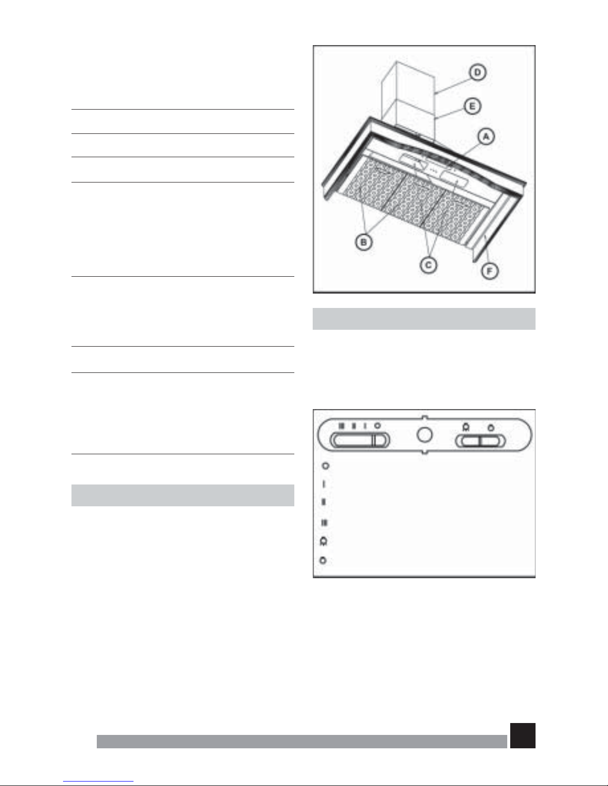
2. Obsługa urządzenia
Rys. 2
Sterowanie wyciągiem umożliwia panel pokazany
na rysunku poniżej.
Wyłącznik
Mała siła ciągu
Średnia siła ciągu
Duża siła ciągu
Włącznik oświetlenia
Wyłącznik oświetlenia
Rys. 2
1. Opis urządzenia
Rys. 1
A Włącznik/Wyłącznik, przełącznik światła i
regulator siły ciągu z lampką kontrolną.
B Filtry metalowe.
C Oświetlenie 2 x 40 W.
D, E Osłona przewodu wentylacyjnego z
regulacją wysokości
F Część dekoracyjna wyciągu
Spis treści
Strona
Istotne informacje 2
1. Opis urządzenia 3
2. Obsługa urządzenia 3
3. Czyszczenie i konserwacja 4
3.1 Czyszczenie obudowy 4
3.2 Rozwiązywanie problemów 4
3.3 Wymiana żarówek 4
4. Wymiary i specyfikacja 5
4.1 Specyfikacja techniczna 5
4.2 Wymiary 5
5. Akcesoria 6
6. Montaż 6
6.1 Montaż modeli: Trenti/ 6
Nubero/ Ventoline
6.2 Montaż modelu Laro
6
7. Filtry z węgla aktywnego 7
Rys. 1
PL
Page 4
4
Gea-Top/001
1. Czyszczenie i konserwacja.
1.1 Czyszczenie obudowy
W żadnym wypadku nie należy używać
metalizowanych gąbek do szorowania ani
proszków i mleczek szorujących, które mogą
rysować czyszczone powierzchnie.
Zewnętrzne powierzchnie urządzenia czyści się
szmatką zwilżoną wodnym roztworem płynnego
detergentu.
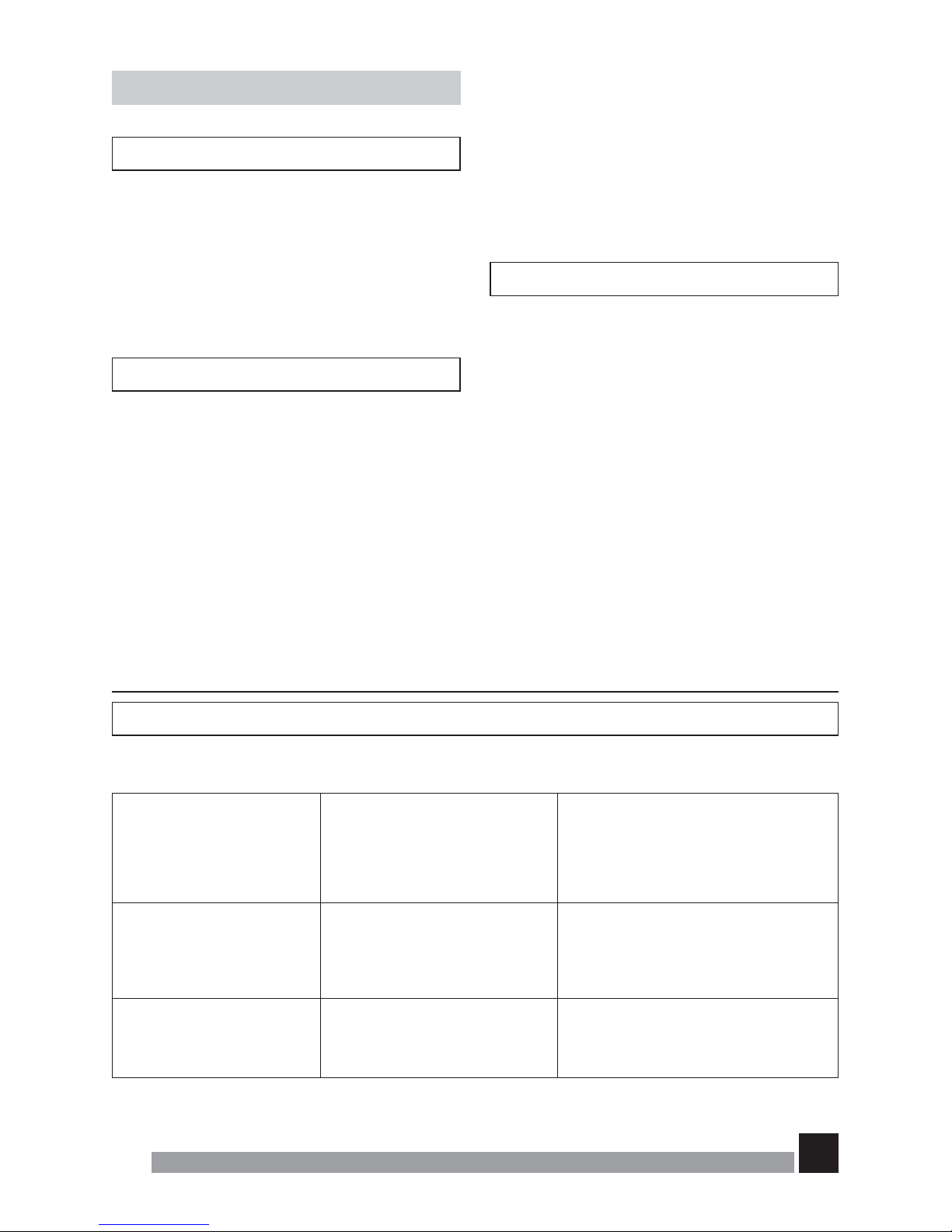
3.2 Rozwiązywanie problemów
Aby wyjąć filtry metalowe z obudowy, nacisnąć
na przycisk a następnie wyjąć filtry. (Rys.3)
Filtry należy myć w zmywarce do naczyń lub
ręcznie uprzednio namaczając w gorącej wodzie
z dodatkiem środka myjącego. Dopuszczalne jest
stosowanie specjalnych środków/sprayów do
usuwania tłuszczu. Płukać pod bieżącą wodą i
pozostawić do wyschnięcia. Filtr należy czyścić
co najmniej raz w miesiącu.
Rozwiązywanie problemów
Przed wezwaniem Punktu Serwisowego należy dokonać sprawdzenia następujących usterek:
Problem
Wyciąg nie pracuje.
Wycią g nie pochłania
prawidłowo lub wibruje.
Żarówki nie świecą się.
Przyczyna
Kabel nie jest podłączony do
zasilania.
Nie ma prądu w gniazdku.
Filtry są nasycone tłuszczem.
Przeszkoda w swobodnym
przepływie powietrza.
Żarówki przepaliły się.
Żarówki poluzowały się.
Rozwiązanie
Podłączyć przewód główny do
gniazdka.
Doprowadzić prąd do gniazdka
Wymienić filtry węglowe lub wyczyścić
filtry metalowe.
Usunąć przeszkodę.
Wymienić żarówki.
Dokręcić żarówki.
Niektóre środki myjące używane w zmywarkach
mogą odbarwić metalową powierzchnię filtra na
czarno. Nie ma to żadnego wpływu na prawidłowe
funkcjonowanie urządzenia.
Prosimy zwrócić uwagę, że podczas gotowania
na filtrze osadza się tłuszcz również, gdy
urządzenia nie jest włączone.
3.1 Wymiana żarówek
•Wyjąć filtry metalowe.
• Wymienić przepaloną żarówkę. Stosować
żarówki 40 W.
• Zamontować filtry metalowe.
PL
Page 5

5
Gea-Top/001
4. Wymiary i specyfikacja
4.1 Specyfikacja techniczna
Napięcie (V) Częstotliwość (Hz) Oświetlenie/ Moc Wydajność (m3/h)
silników (W)
230 - 240 50 Hz 2x40 / 140 480
4.2 Wymiary
MODEL A (mm) B (mm) C (mm) D (mm) E (mm) F (mm)
MIN MAX
LARO 90 900 500 377 877 98 247 188
MODEL A (mm) B (mm) C (mm) D (mm) E (mm) F (mm)
MIN MAX
TRENTI 90 900 502 523 1023 98 218 157
MODEL A (mm) B (mm) C (mm) D (mm) E (mm) F (mm)
MIN MAX
VENTOLINE 60
600 502 488 988 122 157 218
VENTOLINE 90
900 502 494 994 122 157 218
MODEL A (mm) B (mm) C (mm) D (mm) E (mm) F (mm)
MIN MAX
NUBERO 60 600 504 488 988 98 152 142
NUBERO 90 900 510 483 983 98 152 142
TEKA zastrzega sobie prawo do zmian technicznych swoich produktów w zakresie jakim jest to niezbędne, bez
zmian głównych parametrów.
Rys. 4
Rys. 4
Tabliczka znamionowa
PL
Page 6

6
Gea-Top/001
5. Akcesoria
1. redukcja 120/150 mm
2. podpórki do osłony przewodu
wentylacyjnego
3. korki rozporowe (9 x 40)
4. długie śruby (9 x 40)
5. korki rozporowe (5 x 40)
6. długie śruby (5 x 40)
7. filtry węglowe (opcja)
6. Montaż
W celu uzyskania optymalnego odprowadzenia
powietrza należy stosować przewód o przekroju
120 mm. Nie powinien być on dłuższy niż 4 metry
i posiadać więcej niż dwa kolanka 90 stopni.
6.1 Montaż modeli:
Trenti/ Nubero/Ventoline
Rys. 5
1. Zamontować redukcję 150/120 nawet jeśli
średnica wylotu wynosi 125 (Rys. 7);
2. Zaznaczyć miejsca i wywiercić otwory do
kołków (H 9 x 40) i (L 5 x 30) na odpowiedniej
wysokości a następnie dokręcić śruby (H);
3. Zawiesić korpus wyciągu zahaczając o
uchwyt (I) śruby (H) jak na rys. 5b a następnie
dokręcić śruby (L);
4. Zaznaczyć miejsca i wywiercić otwory na
dolną podpórkę (G) do osłony przewodu
wentylacyjnego, dopasować korki rozporowe
(M) i wkręcić śruby (M), następnie
zamocować osłonę przewodu
wentylacyjnego na podpórkach (G) jak na rys.
5c;
5. Dopasować ruchomą (górną) osłonę
przewodu wentylacyjnego do odpowiedniej
wysokości;
6. Zdjąć osłony przewodu wentylacyjnego;
7. Umieścić górną podpórkę (G) na
odpowiedniej wysokości, zaznaczyć miejsca
i wywiercić otwory na kołki (M), wkręcić śruby
(M) i zamocować na nich podpórkę (G);
8. Zamocować wewnętrzny przewód
wentylacyjny za pomocą klamry (nie
dołączona) do wylotu silnika lub do redukcji
150/120 (rys. 7);
9. Jeżeli wewnętrzny przewód wentylacyjny jest
zamontowany, zamocować osłony przewodu
wentylacyjnego zahaczając je za podpórki.
10. Podłączyć przewód wentylacyjny do kanału
wentylacyjnego i zamocować go przy
pomocy klamry.
6.2 Montaż modelu Laro
Rys. 6
1. Zamontować redukcję 150/120 nawet jeśli
średnica wylotu wynosi 125 (Rys. 7);
2. Zaznaczyć miejsca i wywiercić otwory do
kołków (H 9 x 40) i (L 5 x 30) na odpowiedniej
wysokości a następnie dokręcić śruby (H);
3. Zawiesić korpus wyciągu zahaczając o
uchwyt (I) śruby (H) jak na rys. 6b a następnie
dokręcić śruby (L);
4. Zaznaczyć miejsca i wywiercić otwory na
dolną podpórkę (G) do osłony przewodu
wentylacyjnego, dopasować korki rozporowe
(M) i wkręcić śruby (M), następnie
zamocować osłonę przewodu
wentylacyjnego na podpórkach (G) jak na rys.
6c;
5. Dopasować ruchomą (górną) osłonę
przewodu wentylacyjnego do odpowiedniej
wysokości;
6. Zdjąć osłony przewodu wentylacyjnego;
7. Umieścić górną podpórkę (G) na
odpowiedniej wysokości, zaznaczyć miejsca
i wywiercić otwory na kołki (M) i wkręcić śruby
(M) i zamocować na nich podpórkę (G);
PL
Page 7

7
Gea-Top/001
8. Zamocować wewnętrzny przewód
wentylacyjny za pomocą klamry (nie
dołączona) do wylotu silnika lub do redukcji
150/120 (rys. 7);
9. Jeżeli wewnętrzny przewód wentylacyjny jest
zamontowany, zamocować osłony przewodu
wentylacyjnego zahaczając je za podpórki.
10. Podłączyć przewód wentylacyjny do kanału
wentylacyjnego i zamocować go przy
pomocy klamry.
7. Filtry z węgla aktywnego
Rys. 8
W przypadku braku możliwości odprowadzania
oparów na zewnątrz, należy zainstalować filtry z
węgla aktywnego.
Skuteczność działania filtrów węglowych wynosi
od 3 do 6 miesięcy zależnie od intensywności
użycia. Filtrów tych nie można czyścić ani
regenerować.
Jak zamontować filtry węglowe?
Założyć filtry (A) na otwory wlotowe wentylatora
(B) i przekręcić jak na rysunku 8.
PL
Page 8

8
Gea-Top/001
Czyszczenie filtrów metalowych
Rys. 3
6.1 Montaż modeli: Trenti / Nubero / Ventoline
Rys. 5
Rys. 5a
Rys. 5b
Rys. 5c
PL
Page 9

9
Gea-Top/001
6.2 Montaż modelu Laro
Rys. 6
Rys. 6a
Rys. 6b
Rys. 6c
PL
Page 10

10
Gea-Top/001
Montaż przewodu wentylacyjnego
Rys. 7
Filtry z węgla aktywnego
Rys. 8
PL
Page 11

11
Gea-Top/001
Dear client:
Congratulations on your choice. We are sure that
this modern, functional and practical appliance,
made with top quality materials, will fully satisfy
your needs.
Please read every section of this
INSTRUCTIONS MANUAL before using your
kitchen hood for the first time, to ensure
maximum performance from the appliance and
to avoid breakdowns, which may be caused by
incorrect use, as well as to allow any minor
problems to be solved.
Store this manual, as it will provide useful
Information about your kitchen hood at all times
and will also help other people to use it.
Safety instructions
• Please be aware of current local regulations
with reference to domestic electrical fittings
and gas eduction.
• Verify that the tension and frequency of the
network match those indicated on the label
located inside the kitchen hood.
• The appliance must be connected to the
network using a break switch with a universal
cut off and minimum contact separation of 3
mm.
• Once the kitchen hood has been installed,
ensure that the mains cable to the network is
not in contact with any live metal edges.
• Avoid connecting the appliance to conductors
used as exits for fumes produced by a nonelectric energy source, e.g.: boilers, chimneys,
etc.
• If the extractor fan is going to be used
simultaneously with equipment powered by a
non-electric energy source, e.g.: gas cookers,
then the room must have sufficient ventilation.
Excessive fat accumulation in the kitchen hood
and metal filters is a fire risk and may also cause
dripping, therefore the inside of the kitchen hood
and the metal filters must be cleaned at least
once a month.
• The lower part of the kitchen hood must be
fitted at least 50 cm. over electric hobs and 65
cm. over gas or mixed hobs. FOLLOW THE
HOBS´ MANUFACTURER’S MINIMUM
RECOMMENDATIONS fig.5a/6a.
• Never leave gas hobs lit if not covered by a
container. The fat accumulated in the filters
may drip or catch fire when the temperature
increases.
• Avoid cooking under the kitchen hood if the
metal filters are not fitted, e.g.: while they are
being cleaned in the dishwasher.
• Y ou must not produce flames under the kitchen
hood.
• Disconnect the appliance before any interior
manipulation, e.g. during cleaning or
maintenance.
• We recommend the use of gloves and to be
extremely careful when cleaning the kitchen
hood’s interior.
• Your kitchen hood is designed for domestic
use and only for extraction and purification of
fumes produced during food preparation. It will
be your responsibility if it is used for other
purposes, which may be dangerous. The
manufacturer cannot accept responsibility for
damage caused by improper use of the
appliance.
• For repairs please contact the nearest TEKA
T echnical Assistance Service, and always use
genuine spare parts. Repairs or modifications
carried out by unqualified personnel can cause malfunctions or may damage the appliance,
putting your safety in danger.
UK
Page 12

12
Gea-Top/001
Switch on the extractor fan a few minutes before
you start to cook in order to ensure that a steady
air flow has been established before fumes
appear.
Allow the extractor fan to run for several minutes
after you have finished cooking (between 3 to 5
minutes) in order to expel all the grease from the
outlet duct. This prevents the return of grease,
smoke and smells.
2. Instructions for use
fig. 2
You may control the kitchen hood by operating
the controls as shown in the diagram.
Off
Minimum speed
Medium speed
Maximum speed
Light On
Light Off
fig. 2
Index
Page
Safety instructions 11
1. Description of the appliance 12
2. Instructions for use 12
3. Cleaning and maintenance 13
3.1 Cleaning the hood body 13
3.2 Problem solving 13
3.3 Changing the light bulbs 13
4. Size and specifications 14
4.1 T echnical specifications 14
4.2 Dimensions 14
5. Accessories supplied 15
6. Installation 15
6.1 Installing: T renti / Nubero
Ventoline
15
6.2 Installing: Laro 15
7. Active carbon filters (optional) 16
1. Descriptions of the appliance
fig. 1
A On/Off Push button, speed selector, light
and working pilot.
B Metal filters.
C Lamp with two bulbs - 40W.
D,E Vertically adjustable tubecovers.
F Decorative part
fig.1
UK
Page 13

13
Gea-Top/001
3. Cleaning and maintenance
During cleaning and maintenance work, make
sure the safety instructions set out on page
14 are complied with.
3.1 Cleaning the Hood body
• Never use metallic scourers, nor abrasive or
corrosive products.
• Dry the kitchen hood using a cloth that does
not produce fibres.
3.2 Problem solving
To remove the filters from their fittings, press
lightly on the locks and then pull them off (fig.
3).
The metal filters can be cleaned by soaking them
in hot water with neutral detergent until
the fat dissolves and then rinsing them under
the tap or using special anti-grease products.
They can also be washed in a dishwasher. In
this case, it is advisable to stack them vertically
to avoid food residues to stick to them.
Cleaning in a dishwasher with aggressive
detergents or polish may damage the metallic
surface (blackening it), although this will not affect
its fat retention capacity.
Once clean, leave them to dry off and then fit
them onto the kitchen hood.
3.3 Changing the light bulbs
Proceed as follows:
• Remove the metal filters.
• Change the broken/burnt out lamp.
Maximum lamp power is 40W.
• Fit the metal filters.
Problem solving
Proceed with the following checks before calling Technical Services:
Problem
The extractor fan does not
work.
The kitchen hood does not
extract sufficiently or vibrates.
The lamps do not light up.
Possible cause
The mains cable is not connected
to the network.
There is no current in the network.
Filters are satured with fat.
Obstruction in the air conduct.
The lamps are blown.
The lamps are slack.
Solution
Connect mains cable to the network.
Provide current to the network.
Change or clean the active charcoal
and/or metal filters, as the case may be.
Remove the obstruction.
Change the lamps.
Tighten the lamps.
UK
Page 14

14
Gea-Top/001
4. Sizes and specifications
4.1 Technical specifications
Network Network Lights/Motor Motor
tension (V) frequency (Hz) Power (W) V olume (m3/h)
230 - 240 50 Hz 2x40 / 140 480
4.2 Dimensions
PAINTED A (mm) B (mm) C (mm) D (mm) E (mm) F (mm)
STEEL MIN MAX
LARO 90 900 500 377 877 98 247 188
PAINTED A (mm) B (mm) C (mm) D (mm) E (mm) F (mm)
STEEL MIN MAX
TRENTI 90 900 502 523 1023 98 218 157
PAINTED A (mm) B (mm) C (mm) D (mm) E (mm) F (mm)
STEEL MIN MAX
VENTOLINE 60
600 502 488 988 122 157 218
VENTOLINE 90
900 502 494 994 122 157 218
PAINTED A (mm) B (mm) C (mm) D (mm) E (mm) F (mm)
STEEL MIN MAX
NUBERO 60 600 504 488 988 98 152 142
NUBERO 90 900 510 483 983 98 152 142
TEKA INDUSTRIAL S.A. reserves the righ to make changes and corrections to its products as it deems
necessary, without altering their basic characteristics.
fig.4
fig.4
UK
Page 15

15
Gea-Top/001
5. Accessories supplied
1 120/150 mm reduction
2 wall support for tubecover
2 wall plugs (Ø9x40)
2 long bolts (Ø9x40)
6 wall plugs (Ø5x40)
6 long bolts (Ø5x40)
2 active carbon filters (optional)
6. Installation
On installing the kitchen hood make sure thet
Safety Instructions set out on page 14 are
complied with.
T o obtain optimum performance, the external duct
must not to be more than FOUR METERS LONG,
have no more than two 90° angles and its
diameter must be at least Ø120.
6.1 Installing: Trenti / Nubero / Ventoline
fig.5
1. Mount the 150/120 reduction whenever the
air discharge tube is Ø125 (fig.7);
2. Trace and drill the points for fitting the wall
plugs (H Ø9x40) and (L Ø5x30) onto the wall
at the desired height by leaning the hood on
the wall, then tighten the long bolts (H);
3. Hang the kitchen hood, hooking its support
(I)
onto the long bolts (H) as in fig.5b and then
tighten the long bolts (L);
4. Trace and drill the location of the lower support
(G) of the tubecover, fit the wall plugs (M) and
fix it by using the bolts (M), then hook the
fixed chimney to its support (G) as in fig.5c;
5. Mount the mobile chimney and lift it up to the
desired height and mark its shape on the wall;
6. Remove the fixed and mobile chimneys;
7. Centre the upper support (G) around the
shape marked, trace and drill the fixing points
for fitting wall plugs (M), then fix the support
(G) by using bolts (M);
8. Attach the inner tube, possibly flexible, with a
clamp (not supplied) to the motor’s air outlet
or to the 150/120 reduction as the case may
be (fig.7);
9. Once the inner tube is fitted, fit the fixed and
mobile chimney around the extractor fan outlet
and hook them onto respective supports;
10.Connect the scavenging pipe to the outdoor
duct and fix it with a pipe tightening clamp.
6.2 Installing: Laro
fig.6
1. Mount the 150/120 reduction whenever the
air discharge tube is Ø125 (fig.7);
2. Trace and drill the points for fitting the wall
plugs (H Ø9x40) and (L Ø5x30) onto the wall
at the desired height by leaning the hood on
the wall, then tighten the long bolts (H);
3. Hang the kitchen hood, hooking holes (I) onto
the long bolts (H) as in fig.6b and then tighten
the long bolts (L);
4. Trace and drill the location of the lower support
(G) of the tubecover, fit the wall plugs (M) and
fix it by using the bolts (M), then hook the
fixed chimney to its support (G) as in fig.6c;
5. Mount the mobile chimney and lift it up to the
desired height and mark its shape on the wall;
UK
Page 16

16
Gea-Top/001
6. Remove the fixed and mobile chimneys;
7. Centre the upper support (G) around the
shape marked, trace and drill the fixing points
for fitting wall plugs (M), then fix the support
(G) by using bolts (M);
8. Attach the inner tube, possibly flexible, with a
clamp (not supplied) to the motor’s air outlet
or to the 150/120 reduction as the case may
be (fig.7);
9. Once the inner tube is fitted, fit the fixed and
mobile chimney around the extractor fan outlet
and hook them onto respective supports;
10.Connect the scavenging pipe to the outdoor
duct and fix it with a pipe tightening clamp.
7. Active carbon filters (Optional)
fig.8
When exterior gas extraction is not possible, then
the kitchen hood may be set to purify the air by
recycling it through active carbon filters.
The active carbon filters have an active life of
between three to six months, depending on the
individual conditions of use. These filters cannot
be washed nor regenerated. They must be
replaced once their useful life comes to an end.
How to set active carbon filters
1. Put the filters into the lateral draught section
of the motor through the holes presents on
each filter and the pivots of the motor carcass.
Turn as indicated in the diagram fig.8.
UK
Page 17

17
Gea-Top/001
Cleaning the metal filters
fig. 3
6.1 Installing: Trenti / Nubero / Ventoline
fig. 5
fig. 5a
fig. 5b
fig. 5c
UK
Page 18

18
Gea-Top/001
6.2 Installing: Laro
fig. 6
fig. 6a
fig. 6b
fig. 6c
UK
Page 19

19
Gea-Top/001
How to assemble the out-door scavenging pipe
fig. 7
Active charcoal filters
fig. 8
UK
Page 20

20
Gea-Top/001
TEKA GROUP
COUNTRY CITY COMP ANY CC PHONE FAX
Austria
Belgium
Chile
China
Czech Republic
France
Greece
Hungary
Indonesia
Malaysia
Mexico
Poland
Portugal
Russia
Singapore
Thailand
The Netherlands
Turkey
U.K.
U.S.A.
Venezuela
Wien
Zellik
Santiago de Chile
Shangai
Brno
Paris
Athens
Budapest
Jakarta
Kuala Lumpur
Mexico D.F.
Pruszkòw
Ilhavo
Moscow
Singapore
Bangkok
Zoetermeer
Istanbul
Abingdon
Tampa
Caracas
KUPPERSBUSCH GES.M.B.H.
B.V.B.A.KUPPERSBUSCH S.P.R.L.
TEKA CHILE S.A.
TEKA CHINA LTD.
TEKA - CZ, S.R.O.
TEKA FRANCE S.A.R.L.
TEKA HELLAS A.E.
TEKA HUNGARY KFT.
P.T. TEKA BUANA
TEKA KUCHENTECHNIK
(MALAYSIA) SDN. BHD.
TEKA MEXICANA S.A. DE C.V.
TEKA POLSKA SP.ZO.O.
TEKA PORTUGUESA LTDA.
TEKA RUS LLC.
TEKA SINGAPORE PTE LTD.
TEKA (THAILAND) CO. LTD.
TEKA B.V.
TEKA TEKNIK MUTFAK A.S.
TEKA PRODUCTS (UK) LTD.
TEKA USA, INC.
TEKA ANDINA, S.A.
43
32
56
86
42
33
30
36
62
60
52
48
351
7
65
66
31
90
44
1
58
1 - 86680 - 0
2466 - 8740
2 - 273.19.45
21 - 6236 - 2375
05 - 4921 - 0478
1 - 5836 - 4830
210-9760283
1 - 354-21-10
21 - 39052 - 74
3 - 762.01.600
555 - 762.04.90
22 - 738.32.80
234 - 32.95.00
095 - 737 - 4689
6 - 73 - 42415
2 - 5164954
79 - 345.15.89
212 - 274.61.04
1235 - 86.19.16
800 - 419 - 9344
212 - 291.28.21
1 - 86680 - 72
2466 - 7687
2 - 273.10.88
21 - 6236 - 2379
05 - 4921 - 0479
1 - 5836 - 4831
210-9712725
1 - 354-21-15
21 - 39052 - 79
3 - 762.01.626
555 - 762.05.17
22 - 738.32.89
234 - 32.54.57
095 - 737 - 4690
6 - 73 - 46881
2 - 9021484
79 - 345.15.84
212 - 274.56.86
1235 - 83.51.07
813 - 228 - 8604
212 - 291.28.25
TEKA Industrial S.A.
Cajo 17
3901 1 Santander (Spain)
Tel.: 34 - 942 - 354 50 50
Faxl: 34 - 942 - 34 76 94
www.teka.net
TEKA Kuchentechnik GmbH
Sechsheldner Str. 122
35708 Haiger (Germany)
Tel.: 49 - 2771 - 8141-0
Fax: 49 - 2771 - 8141-10
www.teka.net
 Loading...