

Page 1

Operating instructions
Type
TEKA–LMD 508
TEKA Absaug- und Entsorgungstechnologie GmbH
Industriestraße 13 D-46342 Velen
Postfach 1137 D-46334 Velen
Tel.: +49 (0) 2863 9282-0
Fax: +49 (0) 2863 9282-72
E-Mail:
www.teka.eu
Page 2

BA_LMD-508_150602_GB.doc - 2 - 02.06.2015
Contents
1 Diagram/description of the components .............................................................................................. 3
2 Preface................................................................................................................................................. 4
3 Function of the TEKA-LMD 508 ........................................................................................................... 5
4 Safety instructions ............................................................................................................................... 5
5 Commissioning .................................................................................................................................... 6
5.1 Attaching the extractor fittings ...................................................................................................... 6
5.2 Electrical connection of the unit .................................................................................................... 7
6 Operation of the system....................................................................................................................... 8
7 Maintenance ........................................................................................................................................ 8
7.1 Replacing the prefilter matting ...................................................................................................... 9
7.2 Replacing the particle filter ........................................................................................................... 9
7.3 Replacing the activated-carbon cassette ................................................................................... 10
8 Disposal ............................................................................................................................................. 10
9 Technical data ................................................................................................................................... 11
10 List of spare parts .............................................................................................................................. 12
11 Declaration of conformity TEKA-LMD 508........................................................................................ 13
Page 3

BA_LMD-508_150602_GB.doc - 3 - 02.06.2015
1 Diagram/description of the components
Pos.1
Pos.2
Pos.3
Pos.4
Pos.5
Pos.6
Pos.7
Pos.8
Pos.9
Pos.10
Control panel
Instrument cover
Filter housing
Filter door
Ventilator housing
Ventilator door
Castor
Castor with brake
Twist lock fastener
Lifting mechanism
Pos.11
Pos.13
Pos.14
Pos.15
Pos.16
Pos.17
Pos.18
Pos.19
Locking screw for the lifting mechanism
Prefilter mat
Particle filter
Activated-carbon cassette
Air intake fittings
Sound absorption module
Cover plate, or Harting/Sub-D 9-pin socket
Mains supply cable with mains plug
Page 4

BA_LMD-508_150602_GB.doc - 4 - 02.06.2015
2 Preface
One sector of extraction equipment has become very significant in recent years. The filtering of
extracted pollutants and the recycling of filtered air to the working area.
This is a surely a sign that the environmental consciousness of each one of us has altered very
strongly in favour of our environment. For a long time now, no-one has denied that pollution occurs
during production. However, the pollutants depend on the process that is used. One can basically
distinguish between gases and smoke. Smoke could also really be described as dust. If you
examine this dust under a microscope, you will find that it consists of very fine particles, often with
a size of 0.001 mm or smaller, that can enter the lungs.
The classical method of trying to improve the working conditions of polluted workplaces is general
ventilation. In this case, the general rule is a multiple change of air in the workshop, i.e. the
complete volume of air in the workshop is replaced. However, this method only achieves a small
reduction in the level of pollution within the breathing space of the user.
The same applies to the so-called “overhead extraction”, i.e. the installation of large extractor
hoods above the workplaces. With this, the worst air flow imaginable, the pollutants first pass
through the breathing space of the user, and only afterwards are they contained and extracted.
This is surely not the point of the exercise. A much more effective method than overhead/wide-area
extraction is the removal of pollutants directly at their source, with localised extraction. Both the
investment and the operating costs are very much lower if localised extraction is used.
The environmental and workplace-safety measures are especially important requirements for
successful application of a technology, in addition to the technological optimisation of the
processing method. In a time of increasing sensitivity and tougher legislation, the task therefore lies
in making an early assessment of the potential hazards for the workplace and the environment, and
reducing them as appropriate.
Page 5
BA_LMD-508_150602_GB.doc - 5 - 02.06.2015
3 Function of the TEKA-LMD 508
The TEKA - LMD 508 filter equipment is primarily used for localised extraction of dust, smoke
particles and gases. For this purpose, the unit is equipped with two flexible extractor hoses, or an
extractor fitting that is appropriate to the application.
Limits of application:
welding fumes with oil mist, aluminium dust, grinding dust, extraction of metallic dust, water etc.
(If you are uncertain, please contact the manufacturer!)
The polluted air is gathered in by the extractor fitting and transported to the filter equipment through
the extractor hose. Coarse dust particles are then filtered out in the prefilter matting (Pos.13). The
following particle filter (fine filter, Pos.14) extracts the extremely fine smoke particles with an
efficiency of better than 99%. In a further filter stage, the activated-carbon cassette (Pos.15)
adsorbs the gaseous pollutants. The filtered air is then sucked in by the turbines and returned to
the air in the environment through the exhaust mesh on the sound absorption module.
The LMD 508 filter unit can be connected to an external filter monitoring through the Harting or
Sub-D 9-pin socket (Pos.21) (available as an option).
Warning:
As soon as the airflow resistance of the filter has increased to the point where the suction force
decreases, the filter must be replaced, because it is clogged with the extracted dust and smoke
particles.
(see Section 7.1: “Replacing the prefilter matting”, Section 7.2: “Replacing the particle filter” and
Section 7.3: “Replacing the activated-carbon cassette”)
4 Safety instructions
When using electrical equipment, the following basic safety rules must be observed, for protection
against electric shock, injury, or fire hazards.
• Before using the equipment, read and observe these instructions!
• Keep the operating and maintenance instructions in a safe place!
• Never use the equipment to extract easily inflammable or explosive gases!
• Do not employ the unit for setting it in explosive zones, e.g. zone 0, zone 1, zone 2, zone 20,
zone 21, zone 22!
• Do not employ the unit for sucking off burning or glowing materials, e.g. cigarettes, matches,
metallic types of dust and/or splinters, paper, cleaning cloths, etc.!
• Do not employ the unit for sucking off burning and/or inflammatory materials, e.g. oils and/or oil
mist, fats, parting agent (e.g. silicone spray), cleaning agent, etc.!
• Never use the equipment for the extraction of corrosive substances!
• Never use the equipment to suck up any kind of liquid!
• Do not use the equipment for the extraction of organic substances without written approval from
the manufacturer!
• Protect the connectors from heat, moisture, oil, and sharp edges!
• Keep to the permitted supply voltage! (Observe the data on the nameplate!)
• Use only TEKA replacement parts!
Page 6

BA_LMD-508_150602_GB.doc - 6 - 02.06.2015
• Do not operate the equipment without a filter insert!
• Disconnect the equipment from the supply voltage before opening the filter unit!
• The exhaust vent must not be covered up or blocked!
• Always take care that the unit is standing in a stable position, and that the brakes on the castors
are on!
• The filter unit must be disconnected from the mains supply voltage before cleaning or
maintenance, replacing parts, or a functional conversion!
• The filter inserts cannot be regenerated!
• Dispose of the filter inserts in accordance with the legal regulations!
• If an energy-saving automatic start/stop is being used, the earthing cable must be checked for
possible damage before every welding session.
• The unit must not be used if the earthing cable is not in perfect condition.
• If external filter controls are used, the control cable must be checked for possible damage
before every operating session.
• The unit must not be used if the control cable is not in perfect condition!
• The mains supply cable for the unit must be checked regularly for possible damage!
• The unit must not be used if the mains supply cable is not in perfect condition!
• Do not use the filter unit if one or more of its components are faulty, missing, or damaged. In
any of these cases, please call the TEKA service department on +49 (0)2863 92820, or your
local representative.
• When extracting carcinogenic welding fumes, such as from materials containing nickel or
chrome, the ventilation requirements of TRGS 560 „Luftrückführung beim Umgang mit
krebserzeugenden Gefahrstoffen“ (Air recycling when using substances with a carcinogenic
hazard) or the equivalent national regulations must be fulfilled!
Further information on TRGS 560 can be obtained from the BfA - Berufsgenossenschaftliches
Institut für Arbeitssicherheit, in D-53754 Sankt Augustin, Germany.
5 Commissioning
The filter unit is supplied with all connections.
The extractor fittings and any other accessory equipment, must be installed or mounted on the unit
before commissioning.
5.1 Attaching the extractor fittings
• The extractor hose must be pushed into the extractor spout (Pos.16) right up to the stop. If a
second hose is used, this is done as follows:
• Remove the blanking plug from the extractor spout (Pos.16).
• Push the extractor hose into the extractor spout (Pos.16) right up to the stop.
Page 7
BA_LMD-508_150602_GB.doc - 7 - 02.06.2015
5.2 Electrical connection of the unit
• The LMD is either switched on or controlled at the membrane keyboard or through an external
control (e. g. of the machine to be sucked out) (remote switch automatic.
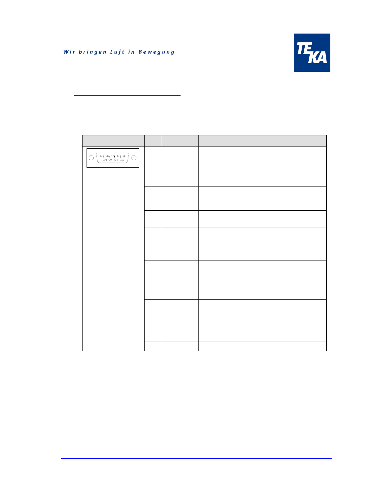
• The connection of the remote switch automatic to the LMD is carried out via a nine-pole cable
with Sub-D9 plugs.
Figure Pin Designation Explanation
Connector socket
Sub-D9,
on the side of the unit
1 Start contact In order to put the LMD into operation a contact
between Pin1 and Pin2 have to be established.
Important: LMD switches off first when the time
programmed has been reached. (Overtravel
time approx. 20 s).
2 EXTIN+ Internal switch contact for starting the turbine
and increasing or reducing the motor speed of
the turbine.
3, 4 „Filter alarm“ Floating output (normal open contact) for
interpretation of the warn alarm „Filter alarm“
5, 6 Operation
control
Floating output (normal open contact) for
interpretation of the operation control.
The alarm at this output always occurs when
the unit identifies an operation.
7 Increasing
turbine
motor speed
In order to increase the performance of the
turbine, a contact between Pin7 and Pin2 is
necessary. Beim Anlegen eines dauerhaften
Kontakts, erhöht sich die Turbinendrehzahl bis
zur Maximaldrehzahl
8 Reducing
turbine
motor speed
In order to reduce the performance of the
turbine, a contact between Pin8 and Pin2 is
necessary. When spreading a permanent
contact, this motor speed of the turbine goes
will be reduced till the motor speed minimum.
9 GND Internal reference potential (Ground)
Table 1: Connection of an external control (arrangement of the plug contact/ terminal assignment of
connection)
Page 8
BA_LMD-508_150602_GB.doc - 8 - 02.06.2015
6 Operation of the system
Attention:
Possibilities of adjustment of the programme, menu navigation ecc of the system you will find in the
attached manual of the steering.
7 Maintenance
The filtering out of dust particles means that the prefilter (coarse) and the particle filter (fine)
become increasingly dirty, and the suction power decreases.
The mechanical filter insert ensures that more than 90% of the pollutants that are sucked in are
trapped in the filter. This is still so, even if the filter insert is partially or completely saturated. But
the suction power of the filter unit drops as the saturation level increases.
The saturation level of the filter is electronically monitored. In order to maintain the rated suction
power of the unit, the filters must be replaced when the red flow volume indicator lamp (Pos.5)
lights up.
The prefilter matting (Pos.13) must be replaced at regular intervals. (see Section 7.1: “Replacing
the prefilter matting”). Please check at least weekly the pollution of the pre-filter mat .
As soon as the airflow resistance of the filter has increased to the point where the suction force
decreases, the particle filter (Pos.14) must be replaced, because it is clogged with the extracted
dust and smoke particles. (see Section 7.2: “Replacing the particle filter”)
The activated-carbon cassette (Pos.15) must be replaced if gas starts to come through to the
clean-air side. At the very latest, the activated-carbon cassette must be replaced when the particle
filter is replaced. (see Section 7.3: “Replacing the activated-carbon cassette”)
The working lives of the prefilter matting, the particle filter, and the activated-carbon cassette are
strongly dependent on the specific conditions of use. So they cannot be determined in advance.
The filter equipment includes a maintenance-free AC-operated turbine.
Warning:
The operation of the filter unit must be stopped while the filter insert is being replaced.
Filter replacement and disposal must only be carried out in well-ventilated rooms, and a proper
respiratory mask must be worn.
We recommend: a respiratory half-mask to DIN EN 141/143 protective level P3 or equivalent
national standard.
The filters should only be replaced by a member of staff who has been properly trained!
Dispose of the filter inserts in accordance with the legal regulations!
If the filter is manually tapped out, washed, or blown out, then the filter material will be damaged.
The pollutants will spread into the air of the room.
Page 9
BA_LMD-508_150602_GB.doc - 9 - 02.06.2015
7.1 Replacing the prefilter matting
The prefilter matting (Pos.13) must be replaced after a certain number of operating hours. The time
depends on the amount of dust that is taken in. At the very latest, the prefilter matting (Pos.13)
must be replaced when the particle filter (Pos.14) is replaced.
This is done as follows:
• Disconnect the filter unit from the mains supply.
• Open the filter door (Pos.4) by use of Allen key.
• Use the fixing screw (Pos.11) to lower the lifting mechanism (Pos.10).
• Pull out the particle filter (Pos.14)
• Take the prefilter matting (Pos.13) out of the particle filter.
• Lay down the new prefilter matting.
Warning:
Use only TEKA prefilter matting!
• Push in the particle filter (Pos.14).
• Use the fixing screw (Pos.11) to raise the lifting mechanism (Pos.10), so that the particle filter
(Pos.14) fits tightly underneath the equipment cover (Pos.2).
• Close the filter door (Pos.4).
• Connect the filter unit to the mains supply. (Observe the data on the nameplate!)
7.2 Replacing the particle filter
If the suction power is falling off, then the particle filter (Pos.14) must be replaced, as follows:
• Disconnect the filter unit from the mains supply.
• Open the filter door (Pos.4) by use of Allen key.
• Use the fixing screw (Pos.11) to lower the lifting mechanism (Pos.10).
• Pull out the particle filter (Pos.14)
• Push in the new particle filter.
Warning:
Use only TEKA particle filters!
• Use the fixing screw (Pos.11) to raise the lifting mechanism (Pos.10), so that the particle filter
(Pos.14) fits tightly underneath the equipment cover (Pos.2).
• Close the filter door (Pos.4).
• Connect the filter unit to the mains supply. (Observe the data on the nameplate!)
Page 10
BA_LMD-508_150602_GB.doc - 10 - 02.06.2015
7.3 Replacing the activated-carbon cassette
If gas escapes on the clean-air side, or the particle filter (Pos.14) is replaced, then the activatedcarbon cassette (Pos.15) must be replaced, as follows:
• Disconnect the filter unit from the mains supply.
• Open the filter door (Pos.4) by use of Allen key.
• Use the fixing screw (Pos.11) to lower the lifting mechanism (Pos.10).
• Pull out the activated-carbon cassette (Pos.15) with the particle filter (Pos.14).
• Push in the new activated-carbon cassette with the particle filter.
Warning:
Use only TEKA activated-carbon cassettes!
• Use the fixing screw (Pos.11) to raise the lifting mechanism (Pos.10), so that the particle filter
(Pos.14) fits tightly underneath the equipment cover (Pos.2).
• Close the filter door (Pos.4).
• Connect the filter unit to the mains supply.
8 Disposal
To ensure perfect operation of your TEKA-LMD 508 extractor unit, and proper disposal of the dust
that has been extracted, we offer the following services:
• Help with finding a waste disposal company in your vicinity.
• On request, we can supply a list of all waste disposal companies in Germany, free of charge.
• A service and maintenance contract.
• A customer help line.
Call our service department for these options: they are at your service – round the clock.
Telephone: +49 (0) 28 63 / 92 82 - 0 Fax: +49 (0) 28 63 / 92 82 72
Page 11
BA_LMD-508_150602_GB.doc - 11 - 02.06.2015
9 Technical data
Warning:
(Observe the data on the nameplate!)
Filter unit
TEKA – LMD 508
Supply voltage
V
230
Current type
Ph
1
Frequency
Hz
50
Motor power
kW
1.2
Max. airflow volume
m³/h
320
Max. partial vacuum
Pa
21000
Enclosure type
IP 54
ISO class
F
Operating voltage V
230
Duty cycle
% 100
Width x depth x height mm 365 x 496 x 737
Weight kg
45
Filter insert
prefilter matting, particle filter,
activated-carbon
Filter area of the particle filter m²
2.2
Extraction performance
% >99
Page 12

BA_LMD-508_150602_GB.doc - 12 - 02.06.2015
10 List of spare parts
Designation: Article no.
Prefilter matting Pos.13
Particle filter Pos.14
Activated-carbon cassette Pos.15
Activated carbon pouring
Turbine 1,2kW with elektronic
Castor Pos.11
Castor with brake Pos.12
Suction hose, length 2,5m, NW45, with air intake
Suction hose, length 5m, NW45, with air intake
10033
10031
97054
100197/507
200421160
94000882
94000881
9631925
9631950
Page 13
BA_LMD-508_150602_GB.doc - 13 - 02.06.2015
11 Declaration of conformity TEKA-LMD 508
TEKA Absaug - und Entsorgungstechnologie GmbH
Industriestraße 13
D - 46342 Velen
Phone.:+49 2863 92820 Fax:+49 2863 928272
e-Mail: [email protected] Internet: http://www.teka.eu
We hereby declare under our sole responsibility that the product mentioned above, from the serial
number A12000010011001 resp. the production number P25000010011001 on, conforms to the
following directives:
Machinery directive: 2006/42/EG
Electromagnetic compatibility: 2014/30/EU
Pressure equipment device: 97/23/EG
Low voltage directive: 2006/95/EG
Applied harmonised standards:
- DIN EN 349
- DIN EN ISO 12100
- DIN EN 60204 Part 1
- DIN EN ISO 13857
- DIN EN ISO 4414
- DIN EN 82079 part 1
plus further national standards and specifications:
- DIN 45635 part 1
This declaration will become void if changes are effected to the suction and filter systems which were
not agreed upon in writing by the manufacturer.
Authorised representative for technical documentation: TEKA GmbH, Technical department, D46342 Velen
Velen, the 29th of december 2014
 Loading...