

Teka E/70 2G AI TR, E/70 3G AI TR, E/70 5G AI TR Instructions For The Installation And Advice For The Maintenance
Page 1
COD. 01050TI – 19.02.2003
Instructions for the installation
and advice for the maintenance
E/70 2G AI TR - E/70 3G AI TR - E/70 5G AI TR
E/70 2G AI TR AL - E/70 3G AI TR AL -
E/70 5G AI TR AL
Instructions Manual
E/70 2G AI TR - E/70 3G AI TR - E/70 5G AI TR
E/70 2G AI TR AL - E/70 3G AI TR AL -
E/70 5G AI TR AL
Page 2
2
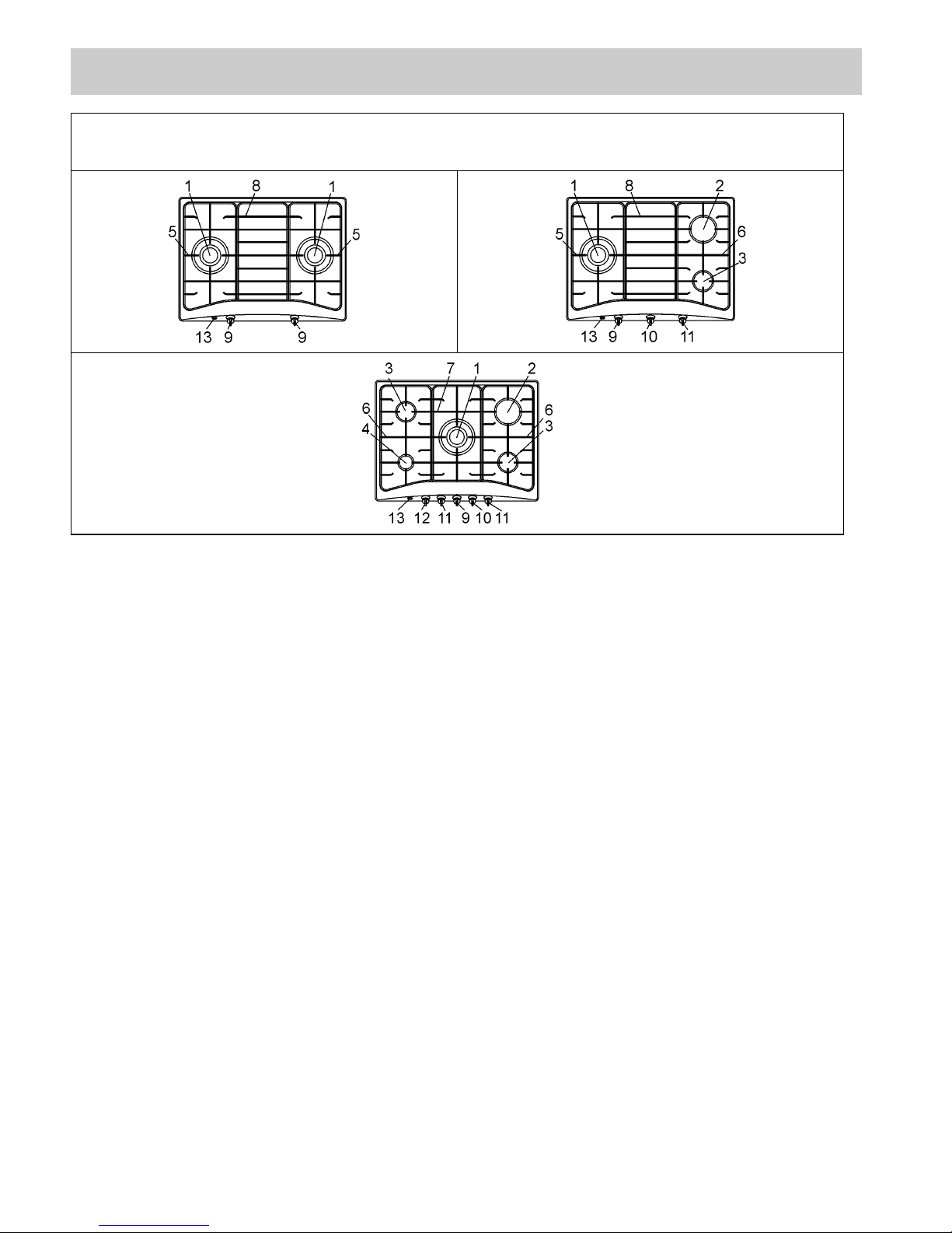
1 Ultra rapid burner of 3700 W (4000 W Hong Kong Towngas)
2 Rapid gas burner of 3000 W (3400 W Hong Kong Towngas)
3 Semirapid gas burner of 1750 W
4 Auxiliary gas burner of 1000 W
5 Enamelled steel pan support 1F
6 Enamelled steel pan support 2F
7 Central enamelled steel pan support for ur
8 Central enamelled steel pan support
9 Burner n° 1 control knob
10 Burner n° 2 control knob
11 Burner n° 3 control knob
12 Burner n° 4 control knob
13 Electric ignition button
Attention: this appliance has been manufactured for domestic use only and it employment by
private person.
DESCRIPTION OF THE HOT PLATES
TYPES: E/70 2G AI TR - E/70 3G AI TR - E/70 5G AI TR
E/70 2G AI TR AL - E/70 3G AI TR AL - E/70 5G AI TR AL
Page 3
3
1) BURNERS
A diagram is screen-printed above each knob on the
front panel. This diagram indicates to which burner
the knob in question corresponds. After having
opened the gas mains or gas bottle tap, light the
burners as described below:
- Manual ignition
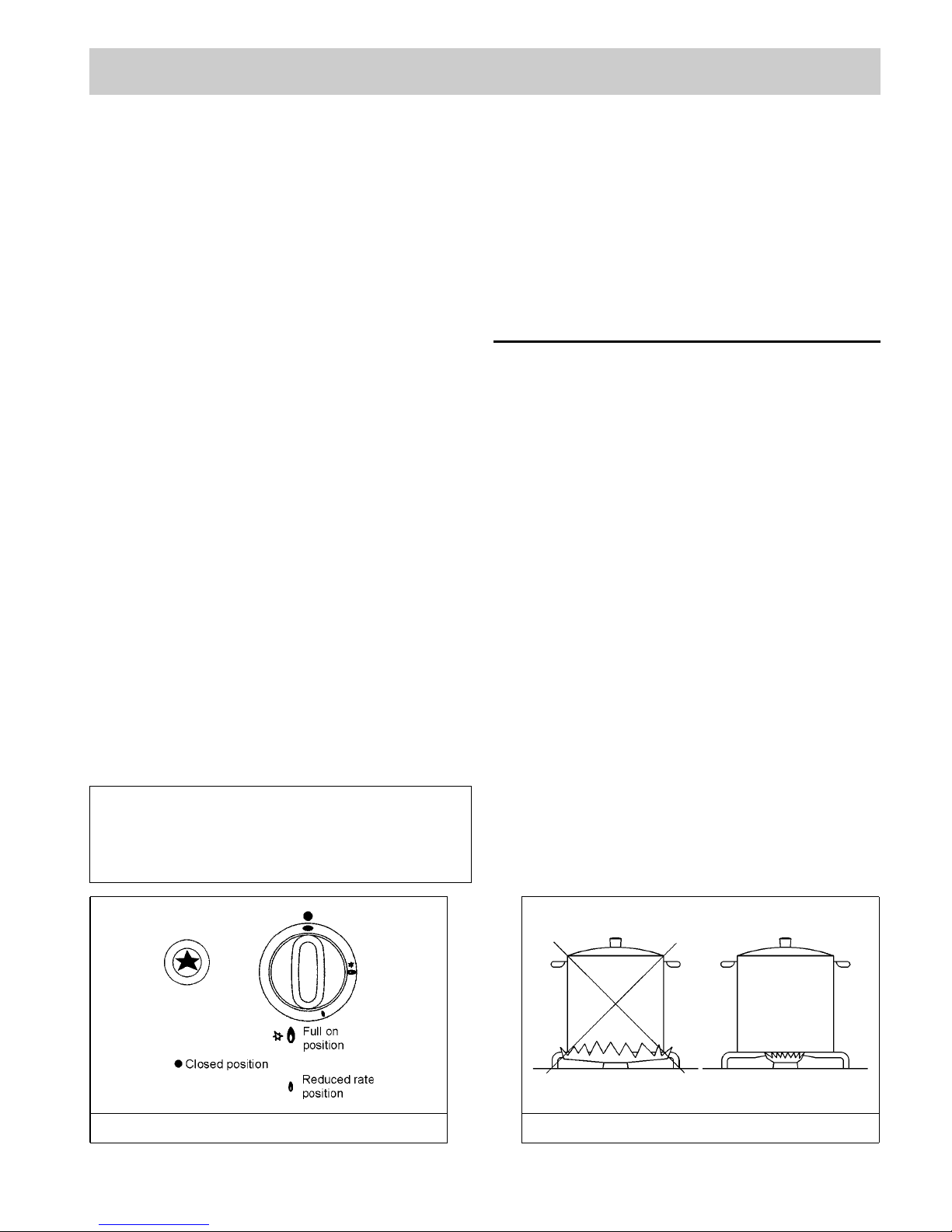
Push and turn the knob corresponding to the
required burner in an anticlockwise direction until it
reaches the full on position (large flame fig. 1), then
place a lighted match near the burner.
- Electrical ignition
Push and turn the knob corresponding to the
required burner in an anticlockwise direction until it
reaches the full on position (large flame fig. 1), then
depress and release the ignition button.
- Automatic electrical ignition
Push and turn the knob corresponding to the required
burner in an anticlockwise direction until it reaches
the full on position (large flame fig. 1), then depress
the knob.
- Lighting burners equipped with flame failure
device
The knobs of burners equipped with flame failure
device must be turned in an anticlockwise direction
until they reach the full on position (large flame fig. 1)
and come to a stop. Now depress the knob in
question and repeat the previously indicated
operations.
Keep the knob depressed for about 10 seconds once
the burner has ignited.
Note: You are advise not to try and light a burner
if the flame divider (Burner Cap) is not correctly
place.
In the event of the Burner flames being
accidentally extinguished, turn off the burner
control and do not attempt to re-ignite the
burner for a least 1 minute.
HOW TO USE THE BURNERS
Bear in mind the following indications in order to
achieve maximum efficiency with the least possible
gas consumption:
- Use adequate pans for each burner (consult the
following table and fig. 2).
- When the pan comes to the boil, set the knob to
the reduced rate position (small flame fig. 1).
- Always place a lid on the pans.
- Use only pan with a flat bottom and in thick metal.
Burners Power ratings Pans Ø in (cm)
Ultra rapid 3700 ÷ 4000 24 ÷ 26
Rapid 3000 ÷ 3400 20 ÷ 22
Semirapid 1750 16 ÷ 18
Auxiliary 1000 10 ÷ 14
WARNINGS:
- Burners with flame failure device may only be
ignited when the relative knob has been set to
the Full on position (large flame fig. 1).
- Matches can be used to ignite the burners in a
blackout.
- Never leave the appliance unattended when the
burners are being used. Make sure there are no
children in the near vicinity. Particularly make
sure that the pan handles are correctly
positioned and keep a chek on foods requiring
oil and grease to cook since these products can
easily catch fire.
- Never use aerosols near the appliance when it is
operating.
- If the built-in hot plate has a lid, any spilt food
should be immediately removed from this before
it is opened. If the appliance has a glass lid, this
could shatter when the hot plate becomes hot.
Always switch off all the burners before closing
the lid.
USE
FIG. 1 FIG. 2
Page 4
4
USE
Notes:
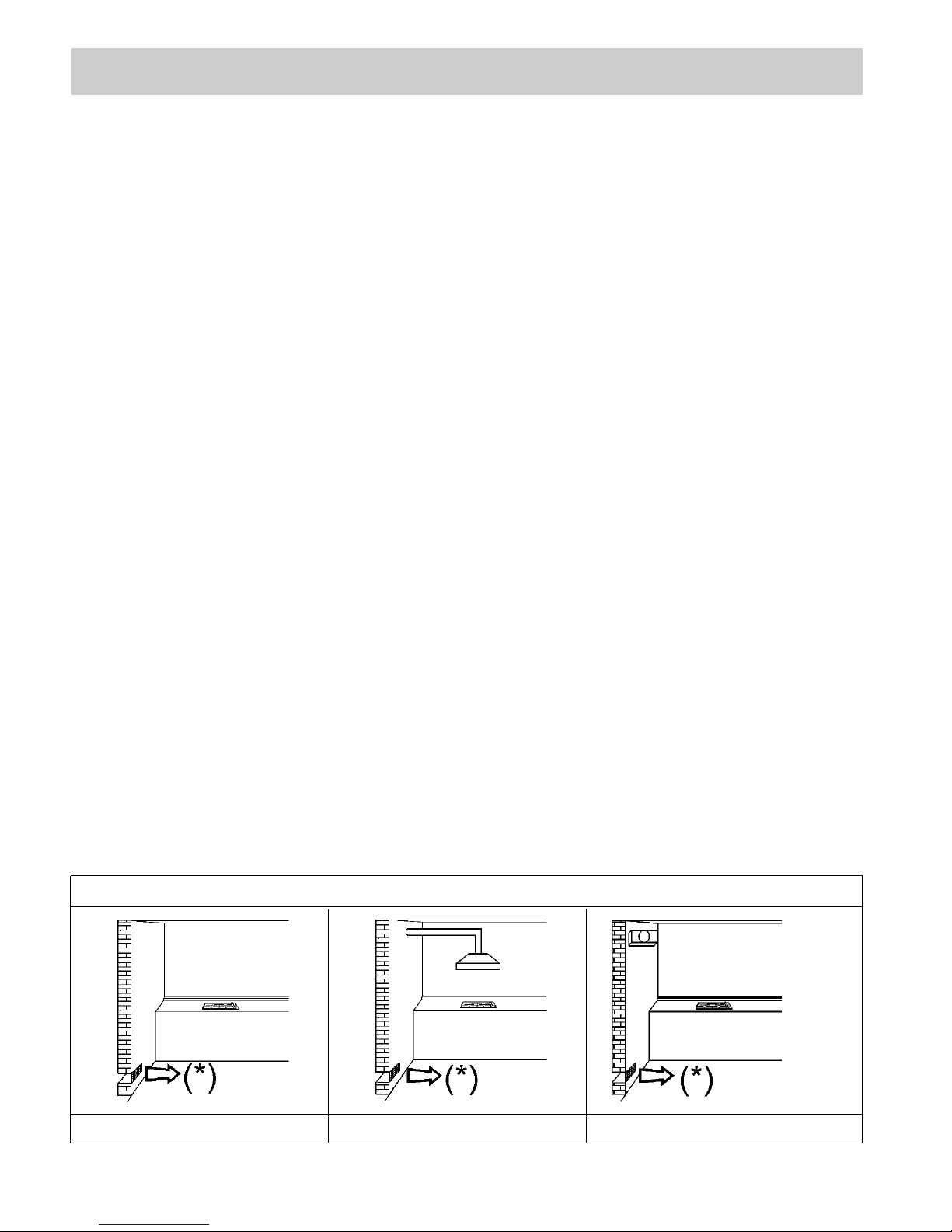
Use of a gas cooking appliance produces heat and moisture in the room in which it is installed. The
room must therefore be well ventilated by keeping the natural air vents clear (fig. 3) and by activating
the mechanical aeration device (suction hood or electric fan fig. 4 and fig. 5).
Intensive and lengthy use of the appliance may require additional ventilation. This can be achieved by
opening a window or by increasing the power of the mechanical exhausting system if installed.
FIG. 3 FIG. 4 FIG. 5
(*) AIR INLET: SEE INSTALLATION CHAPTER (PARAGRAPHS 6 AND 7)
Page 5
5
USE
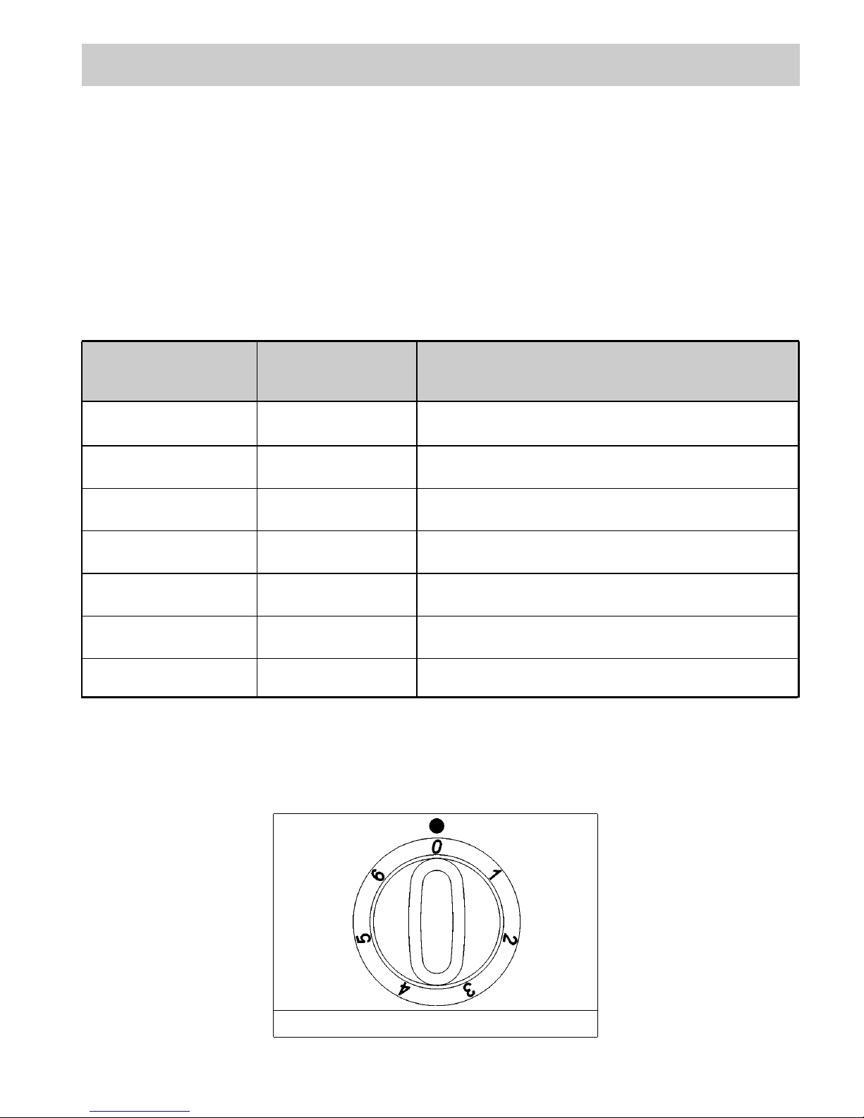
2) HOW TO USE THE ELECTRIC
PLATES
Mixed hot plates may be equipped with a normal or
rapid electric plates. There are controlled by
switches with various positions (see fig. 6) and is
switched on by turning the knob to the required
setting. A diagram is screen-printed above each
knob on the front panel. This diagram indicates to
which electric plates the knob in question
corresponds (see fig. 6). A red warning light will
come on to indicate that the plate is operating.
A purely indicative regulation table for the normal
electric plates is given below.
NORMAL AND
RAPID PLATES
HEAT
INTENSITY
POSSIBLE COOKING
PROCESSES
TABLE
0
1
2
3
4
5
6
Off
Weak
Low
Slow
Medium
Strong
High
To dissolve butter, chocolate, etc.. To heat small
amounts of liquid.
To heat larger amounts of liquid. To prepare cremes
and suces requiring long slow cooking times.
To thaw frozen foods and prepare stews, heat to
boiling point or simmer.
To heat foods to boiling point. To brown delicate meats
and fish.
For escalopes and steaks. To simmer large amounts of
food.
To bring large amounts of liquid to the boil. For frying.
FIG. 6
Page 6
6
USE
WARNINGS:
When the plate is switched on for the first time,
or if it has remained unused for a long period, it
should be dried for 30 minutes on switch position
n° 1. This will eliminate any moisture that may
have been absorbed by the insulating material.
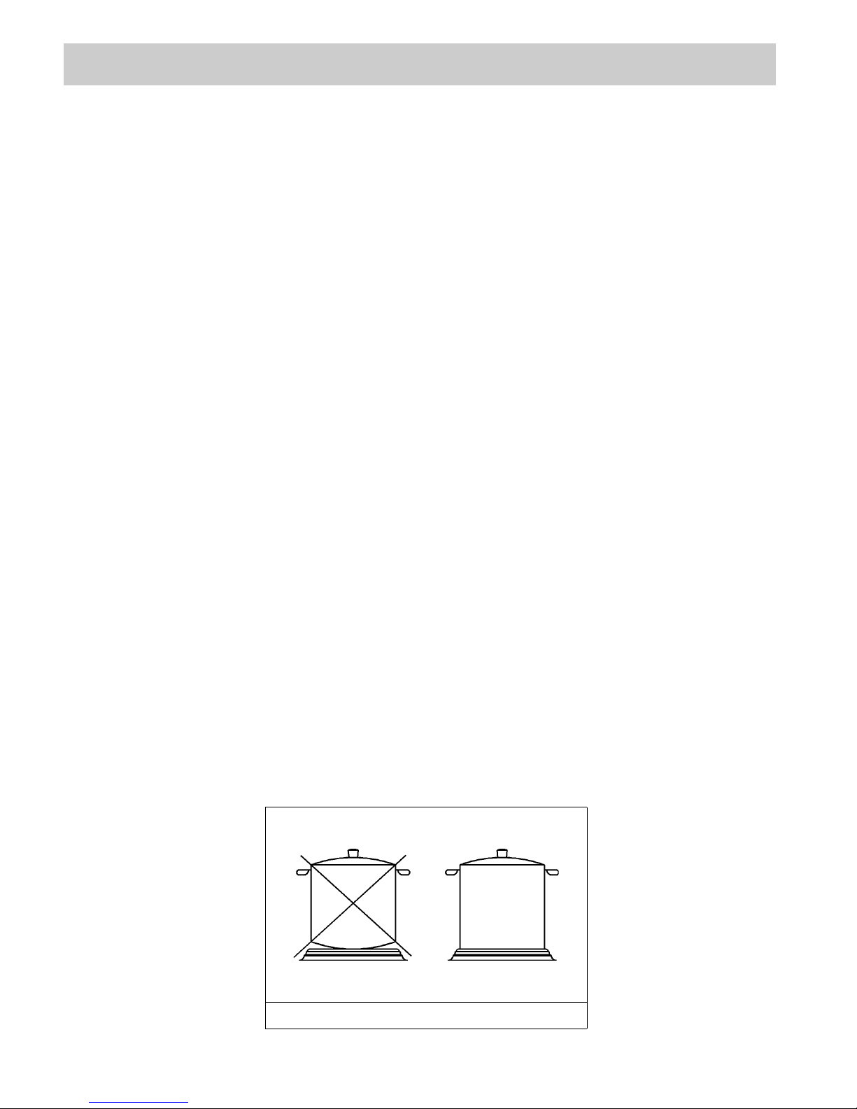
To correctly use the appliance, remember:
- To place a pan on the plate before switching
this on.
- To always use pans with flat and very thick
bottoms (see fig. 7).
- To never use pans that are smaller than the
plate diameters.
- To dry the bottom of the pan before placing it
on the plate.
- Never leave the appliance unattended when
the plates are being used. Make sure that there
are no children in the near vicinity. Particularly
make sure that the pan handles are correctly
positioned and keep a check on foods requiring
oil and grase to cook since these products can
easily catch fire.
- The plates will remain hot for a long period of
time even use after use, never touch them with
the hands or other objects in order to prevent
burns.
- Immediately disconnect the appliance from the
electricity main as soon as cracks are noted on
the surfaces of the plates.
- If the built-in hot plate has a lid, any spilt food
should be immediately removed from this
before it is opened. If the appliance has a glass
lid, this could shatter when the cooker
becomes hot. Always switch off all the plates
before closing the lid.
FIG. 7
Page 7
7
FIG. 8
CLEANING
IMPORTANT:
Always disconnect the appliance from the gas
and electricity mains before carrying out any
cleaning operation.
3) HOT PLATE
Periodically wash the hot plate, the enamelled stell
pan support, the enamelled burner caps “C” and the
burner heads “M” (see fig. 8) with lukewarm soapy
water. Following this, all parts should be thoroughly
rinsed and dried. Never wash them while they are
still warm and never use abrasive powders. Do not
allow vinegar, coffee, milk, salted water, lemon or
tomato juice from remaining in contact with the
enamelled surfaces for long periods of time.
WARNINGS:
Comply with the following instructions, before
remounting the parts:
- Check that burner head slots (fig. 8) have not
become clogged by foreign bodies.
- Check that enamelled burner cap “C” (fig. 8)
have correctly positioned on the burner head. It
must be steady.
- The exact position of the pan support is
established by the rounded corners, which
should be set towards the side edge of the hot
plate.
- Do not force the taps if they are difficult open
or close. Contact the technical assistance
service for repairs.
- Correctly preserve the plate after use by
treating it with special products, easily available
on the market. This will keep the surface of the
plate clean and bright. The operation will also
prevent the formation of rust.
CARE & MAINTAINENCE
To optimize the appearance & Upkeep of Stainless steel:
1)ALWAYS keep S/Steel out of contact from Acid /
Acid-based solvent (Liquid or vapour form).
2) After installation, wipe clean all S/Steel products with
soft damp cloth to rid of any traces of clirt (e.g.
cement dust) or perspiration marks.
In the event whereby presistent sparts appear:
Immediately clean affected areas with S/Steel
Cleaning Powder, using clean damp soft cloth.
Ensure surface is rinsed and thoroughly clean of all
marks and cleaning powder.
Page 8
8
TECHNICAL INFORMATION FOR THE
INSTALLER
Installation, adjustments of controls and
maintenance must only be carried out by a
qualified engineer.
Incorrect installation may cause damage to
persons, animals or property for which the
Manufacturer shall not be considered
responsible.
During the life of the system, the automatic
safety or regulating devices on the appliance
may only be modified by the manufacturer or by
his duly authorized dealer.
4) INSTALLING THE HOT PLATE
Check that the appliance is in a good condition after
having removed the outer packaging and internal
wrappings from around the various loose parts. In
case of doubt, do not use the appliance and contact
qualified personnel.
Never leave the packaging materials (cardboard,
bags, polystyrene foam, nails, etc.) within
children’s reach since they could become
potential sources of danger.
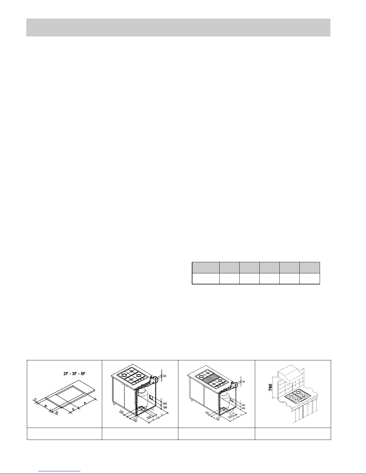
The measurements of the opening made in the top
of the modular cabinet and into which the hot plate
will be installed are indicated in either fig. 9. Always
comply with the measurements given for the hole
into which the appliance will be recessed (see fig. 9
and 10).
The appliance belongs to class 3 and is
therefore subject to all the provisions
established by the provisions governing such
appliances.
4A) CYLINDER HOLDER COMPARTMENT
The dimensions of the cylinder compartment have to
permit the easy loading and unloading of the cylinder.
For an efficient aeration is necessary to make some
small openings in the furniture, as per fig. 9/A and 9/B.
The cylinder holder compartment must have the
following characteristics:
- Resistance to a load.
- No fitment of the cylinder directly on the floor are
allowed.
- The cylinder equipped with governor must be set
or take off from the compartment in a easy way.
- The cylinder cock must be easily accessible.
- The flexible tube musn't be in contact with sharp
edges.
- The cylinder holder compartment and the different
parts of the unit, where the burners are fit, musn't
be in touch inside.
- The aeration openings musn't be occluded when
the unit is installed.
INSTALLATION
ABCDE
2F-3F-5F 553 473 67.5 59.5
175 min.
COMPLY WITH THE DIMENSIONS
FIG. 9 FIG. 9/A FIG. 9/B FIG. 10
Page 9
5) FIXING THE HOT PLATE
The hot plate has a special seal which prevents
liquid from infiltrating into the cabinet. Strictly
comply with the following instructions in order to
correctly apply this seal:
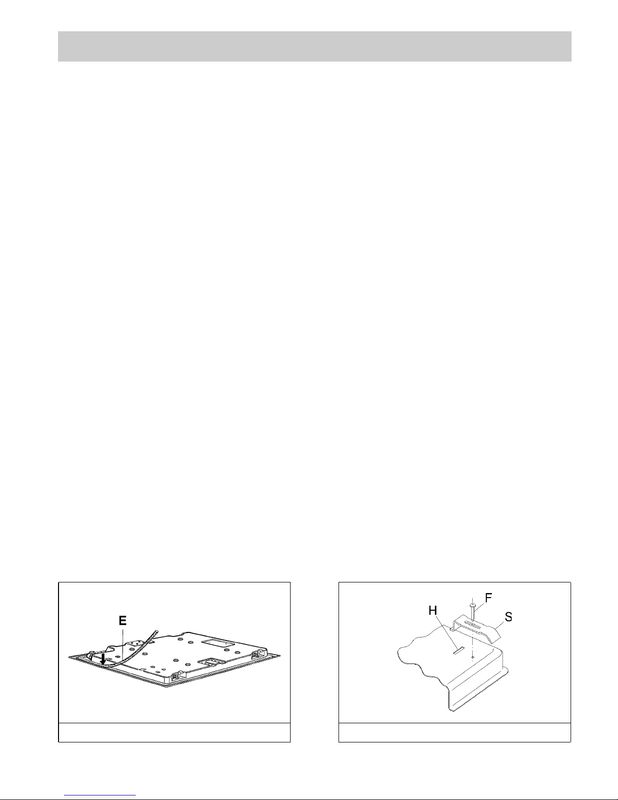
- Detach the seals from their backing, checking that
the transparent protection still adheres to the seal
itself.
- Overturn the hot plate and correctly position seal
“E” (fig. 11) under the edge of the hot plate itself,
so that the outer side of the seal perfectly matches
the outer perimetral edge of the hot plate. The
ends of the strips must fit together without
overlapping.
- Evenly and securely fix the seal to the hot plate,
pressing it in place with the fingers.
- Fix the hob with the proper brackets “S” and fit the
prominent part into the porthole “H” on the
bottom; turn the screw “F” until the bracket “S”
stick on the top (fig. 12).
- The prospective walls (left or right) that exceed the
working table in height must be at a minimum
distance from the cutting as mentionned both in
the columns and the scheme.
Remark: Below is the suggested clearances. Actual
installation will be veried subject to different kitchen
situations.
IMPORTANT INSTALLATION
SPECIFICATIONS
The installer should note that the appliance that
side walls should be no higher than the hot
plate itself. Furthermore, the rear wall, the
surfaces surrounding and adjacent to the
appliance must be able to withstand an
overtemperature of 65 K.
The adhesive used to stick the plastic laminate
to the cabinet must be able to withstand a
temperature of not less than 150° C otherwise
the laminate could come unstuck.
The appliance must be installed in compliance
with the provisions in force.
This appliance is not connected to a device able
to dispose of the combustion fumes. It must
therefore be connected in compliance with the
above mentioned installation standards.
Particular care should be paid to the following
provisions governing ventilation and aeration.
6) ROOM VENTILATION
It is essential to ensure that the room in which the
appliance is installed is permanently ventilated in
order to allow the appliance itself to operate
correctly. The necessary amount of air is that
required for regular gas combustion and ventilation
of the relative room, the volume of which must not
be less than 20 m3. Air must naturally flow through
permanent openings in the walls of the room in
question. These openings must vent the fumes
outdoors and their section must be at least 100 cm
2
(see fig. 3). Construction of the openings must
ensure that the openings themselves may never be
blocked. Indirect ventilation by air drawn from an
adjacent room is also permitted, in strict
compliance with the provisions in force.
7) LOCATION AND AERATION
Gas cooking appliances must always dispose of
their combustion fumes through hoods. These
must be connected to flues, chimneys or straight
outside. If it is not possible to install a hood, an
electric fan can be installed on a window or on a
wall facing outside (see fig. 4). This must be
activated at the same time as the appliance (see
fig. 5), so long as the specifications in the
provisions in force are strictly complied with.
9
INSTALLATION
FIG. 11 FIG. 12
Page 10

10
INSTALLATION
8) GAS CONNECTION
Before connecting the appliance, check that the
values on the data label affixed to the underside
of the hot plate correspond to those of the gas
and electricity mains in the home.
A label on the appliance indicates the
regulating conditions: type of gas and working
pressure. Gas connection must comply with the
pertinent standards and provisions in force.
When gas is supplied through ducts,the
appliance must be connected to the gas supply
system:
o with a rigid steel pipe. The joints of this pipe must
consist of threaded fittings conforming to the
standards.
oWith copper pipe. The joints of this pipe must
consist of unions with mechanical seals.
o With seamless flexible stainless steel pipe. The
length of this pipe must be 2 meters at most and
the seals must comply with the standards.
When the gas is supplied by a bottle, the
appliance must be fuelled by a pressure governor
conforming to the provisions in force and must be
connected:
o with a copper pipe. The joints of this pipe must
consist of unions with mechanical seals.
o With seamless flexible stainless steel pipe. The
length of this pipe must be 2 meters at most and
the seals must comply with the standards. It is
advisable to apply the special adapter to the
flexible pipe. This is easily available from the
shops and facilitates connection with the hose
nipple of the pressure governor on the bottle.
oWith rubber hose pipe in compliance with
standards. The diameter of this hose pipe must
be 8 mm and its length must be no less than 400
mm and no more than 1500 mm. It must be firmly
fixed to the hose nipple by means of the safety
clamp specified by standards.
In case of liquid bottledgas supply, mount a
pressure governor according to the regulations in
force.
To connect the hob with the bottled pressure
governor use a flexible tube 95 cm lenght fastened
by hose clamp.
This tube must run as shown in fig. 9/A and 9/B in
order to avoid contact with the heating surfaces.
At the connection end, verify the gasproof using a
soap solution, never a flame.
WARNINGS:
Remember that the gas inlet union on the
appliance is a 1/2" gas parallel male type in
compliance with ISO 228-1 standards.
Installation of stainless steel pipe and rubber
hose pipe must ensure that it is never able to
touch mobile parts of the built-in cabinet (eg.
drawers). Furthermore, it must not pass through
compartments that could be used for storage
purposes.
When using a rubber hose pipe, it is essential to
comply with the following instructions:
- No part of the pipe must be able to touch parts
the temperature of which exceeds 65 K.
- The pipe must not be pulled or twisted, throttled
or tughtly bent.
- It must not come into contact with sharp edges
or corners.
- It must be easy to inspect the entire pipe length
in order to check its state of wear.
- The pipe must be replaced within the date
stamped on the pipe itself.
- The appliance complies with the provisions of
the following EEC Directives:
90/396 + 93/68 regarding gas safety.
The installer should bear in mind that the mixed
appliance is the Y type. The rear wall, adjacent
and surrounding surfaces must therefore be able
to withstand an overtemperature of 65 K.
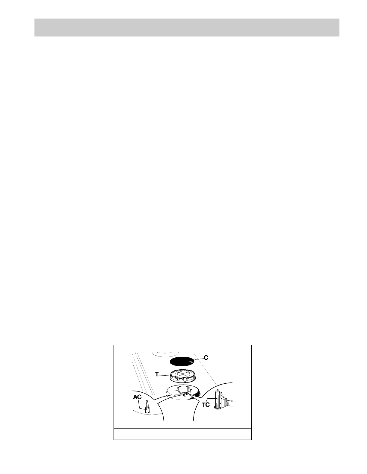
INSTRUCTIONS FOR GAS CONNECTION
Once the gas connection elbow has been fitted,
and if you need to remove it or change its
position, it is important to place the gaskets (A)
in-between the elbow (B) and the LPG nipple (C)
before you tighten it.
Page 11

11
INSTALLATION
9) ELECTRICAL CONNECTION
The electrical connections of the appliance must
be carried out in compliance with the provisions
and standards in force.
Before connecting the appliance, check that:
- The electrical capacity of the mains supply and
current sockets suit the maximum power rating of
the appliance (consult the data label applied to the
underside of the hot plate).
- The socket or system has an efficient earth
connection in compliance with the provisions and
standards in force. The manufacturer declines all
responsibility for failing to comply with these
provisions.
When the appliance is connected to the
electricity main by a socket:
- Fit a standard plug suited to the load indicated on
the data label to the cable.
- Fit the wires following figure 13, taking care of
respecting the following correspondences:
Letter L (live) = brown wire;
Letter N (neutral) = blue wire;
Earth symbol = green - yellow wire.
- The power supply cable must be positioned so that
no part of it is able to reach an overtemperature of
75 K.
- Never use reductions, adapters of shunts for
connection since these could create false contacts
and lead to dangerous overheating.
When the appliance is connected straight to the
electricity main:
- Install an omnipolar circuit-breaker between the
appliance and the electricity main. This circuitbreaker should be sized according to the load
rating of the appliance and possess a minimum 3
mm gap between its contacts.
- Remember that the earth wire must not be
interrupted by the circuit-breaker.
- Alternatively, the electrical connection may also be
protected by a high sensitivity differential circuitbreaker.
You are strongly advised to fix the relative yellowgreen earth wire to an efficient earthing system.
WARNINGS:
All our appliances are designed and
manufactured in compliance with European
standards EN 60 335-1 and EN 60 335-2-6 plus
the relative amendments.
The appliance complies with the provisions of
the following EEC Directives:
- 89/336 + 92/31 + 93/68 regarding to
electromagnetic compatibility.
- 73/23 + 93/68 regarding electrical safety.
FIG. 13
Page 12

12
10) INSTALLING THE HOT PLATE
WITH THE BATTERY
Check that the appliance is in a good condition after
having removed the outer packaging and internal
wrappings from around the various loose parts. In
case of doubt, do not use the appliance and contact
qualified personnel.
Never leave the packaging materials (cardboard,
bags, polystyrene foam, nails, etc.) within
children’s reach since they could become
potential sources of danger.
The measurements of the opening made in the top
of the modular cabinet and into which the hot plate
will be installed are indicated in either fig. 9. Always
comply with the measurements given for the hole
into which the appliance will be recessed (see fig. 9
and 10).
The appliance belongs to class 3 and is therefore
subject to all the provisions established by the
provisions governing such appliances.
11) FIXING THE HOT PLATE
The hot plate has a special seal which prevents
liquid from infiltrating into the cabinet. Strictly
comply with the following instructions in order to
correctly apply this seal:
- Detach the seals from their backing, checking that
the transparent protection still adheres to the seal
itself.
- Overturn the hot plate and correctly position seal
“E” (fig. 11) under the edge of the hot plate itself,
so that the outer side of the seal perfectly matches
the outer perimetral edge of the hot plate. The
ends of the strips must fit together without
overlapping.
- Unscrew the ignition cap “T” (see fig. 14) and fit a
1,5 V battery (not included in the appliance) with
the positive “+” polarity turn inside. Rescrew the
cap.
- Evenly and securely fix the seal to the hot plate,
pressing it in place with the fingers.
- Fix the hob with the proper brackets “S” and fit the
prominent part into the porthole “H” on the
bottom; turn the screw “F” until the bracket “S”
stick on the top (fig. 12).
INSTALLATION
FIG. 14
Page 13

13
Always disconnect the appliance from the
electricity main before making any adjustments.
All seals must be replaced by the technician at
the end of any adjustments or regulations.
12) TAPS
“Reduced rate” adjustment
- Switch on the burner and turn the relative knob to
the “Reduced rate” position (small flame fig.1).
- Remove knob “M” (fig. 15) of the tap, which is
simply pressed on to its rod.
- Insert a small screwdriver “D” into hole “C” (fig. 15)
and turn the throttle screw to the right or left until
the burner flame has been adequately regulated to
the “Reduced rate” position.
Check that the flame does not go out when the knob
is sharply switched from the “Full on” to the
“Reduced rate” position.
It is understood that only burners operating with
G20 gas should be subjected to the above
mentioned adjustments. The screw must be fully
locked when the burners operate with G30 or
G31.
ADJUSTMENTS
FIG. 15
Page 14

14
13) REPLACING THE INJECTORS
The burners can be adapted to different types of gas
by mounting injectors suited to the type of gas in
question. To do this, first remove the burner tops
using a wrench “B”. Now unscrew injector “A” (see
fig. 16) and fit a injector corresponding to the utilized
type of gas in its place.
It is advisable to strongly tighten the injector in
place.
After the injectors have been replaced, the
burners must be regulated as explained in
paragraphs 11. The technician must reset any
seals on the regulating or pre-regulating devices.
The envelope with the injectors and the labels can
be included in the kit, or at disposal to the
authorized customer Service Centre.
For the sake of convenience, the nominal rate table
also lists the heat inputs of the burners, the diameter
of the injectors and the working pressures of the
various types of gas.
CONVERSIONS
BURNER ARRANGEMENT ON THE HOT PLATE
BUTANE 28 - 30 269 93 1400 3700 62
PROPANE 37 264 93 1400 3700 62
NATURAL 20 352 124 Y 1400 3700 62
BUTANE 28 - 30 218 85 750 3000 45
PROPANE 37 214 85 750 3000 45
NATURAL 20 286 115 Y 750 3000 45
BUTANE 28 - 30 127 65 500 1750 35
PROPANE 37 125 65 500 1750 35
NATURAL 20 167 97 Z 500 1750 35
BURNERS
N°
DESCRIPTION
GAS
NORMAL
PRESSURE
NORMAL
RATE
INJECTOR
DIAMETER
NOMINAL HEAT
INPUT (W)
mbar g/h l/h 1/100 mm MIN. MAX. 1/100 mm
OTHER MARKETS
BUTANE 28 - 30 73 50 400 1000 30
PROPANE 37 71 50 400 1000 30
NATURAL 20 95 72 X 400 1000 30
1 ULTRA RAPID
2 RAPID
3 SEMIRAPID
4 AUXILIARY
BY
PASS
FIG. 16
Page 15

15
CONVERSIONS
BURNER ARRANGEMENT ON THE HOT PLATE
HONG KONG MARKET
LPG 30 269 95 1400 3700 62
TOWN 10 833 350 6 1400 4000 62
LPG 30 218 85 750 3000 45
TOWN 10 708 300 3 750 3400 45
LPG 30 127 65 500 1750 35
TOWN 10 365 190 2 500 1750 35
BURNERS
N°
DESCRIPTION
GAS
NORMAL
PRESSURE
NORMAL
RATE
INJECTOR
DIAMETER
NOMINAL HEAT
INPUT (W)
mbar g/h l/h 1/100 mm MIN. MAX. 1/100 mm
LPG 30 73 50 400 1000 30
TOWN 10 208 145 2 400 1000 30
1 ULTRA RAPID
2 RAPID
3 SEMIRAPID
4 AUXILIARY
BY
PASS
CHINA MARKET
LPG 30 269 85 1400 3700 62
NATURAL 20 352 130 T 1400 3700 62
TOWN (SHANGHAI) 10 971 330 3 1400 3700 62
TOWN (GUANGZHOU) 20 472 165 2 1400 3700 62
LPG 30 218 70 750 3000 45
NATURAL 20 286 91 Z 750 3000 45
TOWN (SHANGHAI) 10 787 260 3 750 3000 45
TOWN (GUANGZHOU) 20 383 140 1 750 3000 45
LPG 30 127 55 500 1750 35
NATURAL 20 167 80 Y 500 1750 35
TOWN (SHANGHAI) 10 459 200 2 500 1750 35
TOWN (GUANGZHOU) 20 223 110 1 500 1750 35
BURNERS
N°
DESCRIPTION
GAS
NORMAL
PRESSURE
NORMAL
RATE
INJECTOR
DIAMETER
NOMINAL HEAT
INPUT (W)
mbar g/h l/h 1/100 mm MIN. MAX. 1/100 mm
LPG 30 73 50 400 1000 30
NATURAL 20 95 72 X 400 1000 30
TOWN (SHANGHAI) 10 262 135 11 400 1000 30
TOWN (GUANGZHOU) 20 128 87 400 1000 30
1 ULTRA RAPID
2 RAPID
3 SEMIRAPID
4 AUXILIARY
BY
PASS
Page 16

16
CONVERSIONS
BURNER ARRANGEMENT ON THE HOT PLATE
TAIWAN MARKET
SINGAPORE MARKET
LPG 30 269 95 1400 3700 62
NATURAL 20 363 135 T 1400 3700 62
LPG 30 218 85 750 3000 45
NATURAL 20 294 115 Y 750 3000 45
LPG 30 127 65 500 1750 35
NATURAL 20 172 97 Z 500 1750 35
BURNERS
N°
DESCRIPTION
GAS
NORMAL
PRESSURE
NORMAL
RATE
INJECTOR
DIAMETER
NOMINAL HEAT
INPUT (W)
mbar g/h l/h 1/100 mm MIN. MAX. 1/100 mm
LPG 30 73 50 400 1000 30
NATURAL 20 98 72 X 400 1000 30
1 ULTRA RAPID
2 RAPID
3 SEMIRAPID
4 AUXILIARY
BY
PASS
LPG 30 244 93 1400 3350 62
TOWN 10 600 300 6 1400 3100 62
LPG 30 218 85 750 3000 45
TOWN 10 581 270 3 750 3000 45
LPG 30 127 65 500 1750 35
TOWN 10 339 190 2 500 1750 35
BURNERS
N°
DESCRIPTION
GAS
NORMAL
PRESSURE
NORMAL
RATE
INJECTOR
DIAMETER
NOMINAL HEAT
INPUT (W)
mbar g/h l/h 1/100 mm MIN. MAX. 1/100 mm
LPG 30 73 50 400 1000 30
TOWN 10 194 145 2 400 1000 30
1 ULTRA RAPID
2 RAPID
3 SEMIRAPID
4 AUXILIARY
BY
PASS
COREA MARKET
LPG 28 - 30 269 93 1400 3700 62
NATURAL 20 352 124 Y 1400 3700 62
LPG 28 - 30 218 85 750 3000 45
NATURAL 20 287 115 Y 750 3000 45
LPG 28 - 30 127 65 500 1750 35
NATURAL 20 167 97 Z 500 1750 35
BURNERS
N°
DESCRIPTION
GAS
NORMAL
PRESSURE
NORMAL
RATE
INJECTOR
DIAMETER
NOMINAL HEAT
INPUT (W)
mbar g/h l/h 1/100 mm MIN. MAX. 1/100 mm
LPG 28 - 30 73 50 400 1000 30
NATURAL 20 95 72 X 400 1000 30
1 ULTRA RAPID
2 RAPID
3 SEMIRAPID
4 AUXILIARY
BY
PASS
Page 17

17
SERVICING
Always disconnect the appliance from the
electricity and gas mains before proceeding with
any servicing operation.
14) REPLACING HOT PLATE PARTS
When parts housed within the hot plate need
replacing, it is first necessary to remove the hot
plate itself from the cabinet, to overturn it, unscrew
screws “V” and to remove part (see fig. 17).
After having carried out the above listed
operations, the burners (fig. 18), taps (fig. 19) and
electrical components can all be replaced (fig. 20).
NB: the ignition bar must be removed before
replacing the taps in appliances with automatic
ignition systems.
It is advisable to change seal “D” whenever a tap is
replaced to ensure a perfect tightness.
Greasing the taps (see fig. 21 - 22)
If a tap becomes stiff to operate, it must be
immediately greased in compliance with the
following instructions:
- Remove the tap.
- Clean the cone and its housing using a cloth
soaked in diluent.
- Lightly spread the cone with the relative grease.
- Fit the cone back in place, operate it several times
and then remove it again. Eliminate any excess
grease and check that the gas ducts have not
become clogged.
- Fit all parts back in place, complying with the
demounting order in reverse.
- At the connection end, verify the gasproof using a
soap solution, never a flame.
To facilitate the servicing technician’s task, here is a
chart with the types and sections of the powering
cables and the ratings of the electrical components.
FIG. 20 FIG. 21 FIG. 22
FIG. 17 FIG. 18
FIG. 19
Page 18

18
SERVICING
15) REPLACING THE BATTERY
To change the battery (see fig. 23) comply with
following instructions:
- Unscrew cap “T” and remove exausty battery.
- Insert a 1,5 V new battery. The positive polarity
“+” is turn over inside.
- Rescrew the cap “T”.
- Re-assembly all the movable parts.
WARNING:
The batteries contain a dangerous material for
our ambient. Always put them in a separate and
safe container.
If you eliminate your appliance, remember to
take off the battery.
FIG. 23
CAUTION
The device should not be operated for more than 15 second.
If after 15 second, the burner has not lit, stop operating the device & open the compartment door
and/or wait at least 1 minutes before attempting a further ignite of the burner.
In the event of the flame being accidentally extinguished, turn off the burner control and do not
attempt to re-ignite the burner for at least 1 minutes.
Page 19

19
SERVICING
Gas hot plate H05 RR - F Section 3 X 0.75 mm
2
TYPE OF TYPE OF SINGLE - PHASE
HOT PLATE CABLE POWER SUPPLY
CABLE TYPES AND SECTIONS
ATTENTION!!!
If the power supply cable is replaced, the installe should leave the ground wire longer than the phase
conductors (fig. 24) and comply with the recommendations given in paragraph 9.
FIG. 24
Page 20

20
TECHNICAL DATA ON THE DATA LABEL
5 BURNERS
BUTANE = 28 - 30 mbar
PROPANE = 37 mbar
NATURAL = 20 mbar
Tot. Nom. Gas Rate = 11.2 kW
Tot. Nom. LPG Rate = 814 g/h
Voltage = 220 – 230 V ~
Frequency = 50 Hz
3 BURNERS (LEFT UR)
BUTANE = 28 - 30 mbar
PROPANE = 37 mbar
NATURAL = 20 mbar
Tot. Nom. Gas Rate = 8.45 kW
Tot. Nom. LPG Rate = 614 g/h
Voltage = 220 – 230 V ~
Frequency = 50 Hz
2 UR BURNERS
BUTANE = 28 - 30 mbar
PROPANE = 37 mbar
NATURAL = 20 mbar
Tot. Nom. Gas Rate = 7.4 kW
Tot. Nom. LPG Rate = 538 g/h
Voltage = 220 – 230 V ~
Frequency = 50 Hz
OTHER MARKETS
5 BURNERS
BUTANE = 28 - 30 mbar
PROPANE = 37 mbar
NATURAL = 20 mbar
Tot. Nom. Gas Rate = 11.2 kW
Tot. Nom. LPG Rate = 814 g/h
Voltage = 1.5 V DC
3 BURNERS (LEFT UR)
BUTANE = 28 - 30 mbar
PROPANE = 37 mbar
NATURAL = 20 mbar
Tot. Nom. Gas Rate = 8.45 kW
Tot. Nom. LPG Rate = 614 g/h
Voltage = 1.5 V DC
2 UR BURNERS
BUTANE = 28 - 30 mbar
PROPANE = 37 mbar
NATURAL = 20 mbar
Tot. Nom. Gas Rate = 7.4 kW
Tot. Nom. LPG Rate = 538 g/h
Voltage = 1.5 V DC
OTHER MARKETS WITH BATTERY
Page 21

21
TECHNICAL DATA ON THE DATA LABEL
HONG KONG MARKET
5 BURNERS
LPG = 30 mbar
TOWN = 10 mbar
Tot. Nom. LPG Gas Rate = 11.2 kW
Tot. Nom. H.K. Towngas Rate = 11.9 kW
Tot. Nom. LPG Rate = 814 g/h
Voltage = 220 – 230 V ~
Frequency = 50 Hz
3 BURNERS (LEFT UR)
LPG = 30 mbar
TOWN = 10 mbar
Tot. Nom. LPG Gas Rate = 8.45 kW
Tot. Nom. H.K. Towngas Rate = 9.15 kW
Tot. Nom. LPG Rate = 614 g/h
Voltage = 220 – 230 V ~
Frequency = 50 Hz
2 UR BURNERS
LPG = 30 mbar
TOWN = 10 mbar
Tot. Nom. LPG Gas Rate = 7.4 kW
Tot. Nom. H.K. Towngas Rate = 8 kW
Tot. Nom. LPG Rate = 538 g/h
Voltage = 220 – 230 V ~
Frequency = 50 Hz
5 BURNERS
LPG = 30 mbar
TOWN = 10 mbar
Tot. Nom. LPG Gas Rate = 11.2 kW
Tot. Nom. H.K. Towngas Rate = 11.9 kW
Tot. Nom. LPG Rate = 814 g/h
Voltage = 1.5 V DC
3 BURNERS (LEFT UR)
LPG = 30 mbar
TOWN = 10 mbar
Tot. Nom. LPG Gas Rate = 8.45 kW
Tot. Nom. H.K. Towngas Rate = 9.15 kW
Tot. Nom. LPG Rate = 614 g/h
Voltage = 1.5 V DC
2 UR BURNERS
LPG = 30 mbar
TOWN = 10 mbar
Tot. Nom. LPG Gas Rate = 7.4 kW
Tot. Nom. H.K. Towngas Rate = 8 kW
Tot. Nom. LPG Rate = 538 g/h
Voltage = 1.5 V DC
HONG KONG WITH BATTERY
Page 22

TECHNICAL DATA ON THE DATA LABEL
22
CHINA MARKET
5 BURNERS
LPG = 30 mbar
NATURAL = 20 mbar
TOWN (SHANGHAI) = 10 mbar
TOWN (GUANGZHOU) = 20 mbar
Tot. Nom. Gas Rate = 11.2 kW
Tot. Nom. LPG Rate = 814 g/h
Voltage = 220 – 230 V ~
Frequency = 50 Hz
3 BURNERS (LEFT UR)
LPG = 30 mbar
NATURAL = 20 mbar
TOWN (SHANGHAI) = 10 mbar
TOWN (GUANGZHOU) = 20 mbar
Tot. Nom. Gas Rate = 8.45 kW
Tot. Nom. LPG Rate = 614 g/h
Voltage = 220 – 230 V ~
Frequency = 50 Hz
2 UR BURNERS
LPG = 30 mbar
NATURAL = 20 mbar
TOWN (SHANGHAI) = 10 mbar
TOWN (GUANGZHOU) = 20 mbar
Tot. Nom. Gas Rate = 7.4 kW
Tot. Nom. LPG Rate = 538 g/h
Voltage = 220 – 230 V ~
Frequency = 50 Hz
5 BURNERS
LPG = 30 mbar
NATURAL = 20 mbar
TOWN (SHANGHAI) = 10 mbar
TOWN (GUANGZHOU) = 20 mbar
Tot. Nom. Gas Rate = 11.2 kW
Tot. Nom. LPG Rate = 814 g/h
Voltage = 1.5 V DC
3 BURNERS (LEFT UR)
LPG = 30 mbar
NATURAL = 20 mbar
TOWN (SHANGHAI) = 10 mbar
TOWN (GUANGZHOU) = 20 mbar
Tot. Nom. Gas Rate = 8.45 kW
Tot. Nom. LPG Rate = 614 g/h
Voltage = 1.5 V DC
2 UR BURNERS
LPG = 30 mbar
NATURAL = 20 mbar
TOWN (SHANGHAI) = 10 mbar
TOWN (GUANGZHOU) = 20 mbar
Tot. Nom. Gas Rate = 7.4 kW
Tot. Nom. LPG Rate = 538 g/h
Voltage = 1.5 V DC
CHINA MARKET WITH BATTERY
Page 23

23
TECHNICAL DATA ON THE DATA LABEL
TAIWAN MARKET
5 BURNERS
LPG = 30 mbar
NATURAL = 20 mbar
Tot. Nom. Gas Rate = 11.2 kW
Tot. Nom. LPG Rate = 814 g/h
Voltage = 110 V ~
Frequency = 60 Hz
3 BURNERS (LEFT UR)
LPG = 30 mbar
NATURAL = 20 mbar
Tot. Nom. Gas Rate = 8.45 kW
Tot. Nom. LPG Rate = 614 g/h
Voltage = 110 V ~
Frequency = 60 Hz
2 UR BURNERS
LPG = 30 mbar
NATURAL = 20 mbar
Tot. Nom. Gas Rate = 7.4 kW
Tot. Nom. LPG Rate = 538 g/h
Voltage = 110 V ~
Frequency = 60 Hz
5 BURNERS
LPG = 30 mbar
NATURAL = 20 mbar
Tot. Nom. Gas Rate = 11.2 kW
Tot. Nom. LPG Rate = 814 g/h
Voltage = 1.5 V DC
3 BURNERS (LEFT UR)
LPG = 30 mbar
NATURAL = 20 mbar
Tot. Nom. Gas Rate = 8.45 kW
Tot. Nom. LPG Rate = 614 g/h
Voltage = 1.5 V DC
2 UR BURNERS
LPG = 30 mbar
NATURAL = 20 mbar
Tot. Nom. Gas Rate = 7.4 kW
Tot. Nom. LPG Rate = 538 g/h
Voltage = 1.5 V DC
TAIWAN MARKET WITH BATTERY
Page 24

24
TECHNICAL DATA ON THE DATA LABEL
SINGAPORE MARKET
5 BURNERS
LPG = 30 mbar
TOWN = 10 mbar
Tot. Nom. LPG Gas Rate = 10.85 kW
Tot. Nom. Towngas Rate = 10.6 kW
Tot. Nom. LPG Rate = 789 g/h
Voltage = 220 – 230 V ~
Frequency = 50 Hz
3 BURNERS (LEFT UR)
LPG = 30 mbar
TOWN = 10 mbar
Tot. Nom. LPG Gas Rate = 8.1 kW
Tot. Nom. Towngas Rate = 7.85 kW
Tot. Nom. LPG Rate = 589 g/h
Voltage = 220 – 230 V ~
Frequency = 50 Hz
2 UR BURNERS
LPG = 30 mbar
TOWN = 10 mbar
Tot. Nom. LPG Gas Rate = 6.7 kW
Tot. Nom. Towngas Rate = 6.2 kW
Tot. Nom. LPG Rate = 488 g/h
Voltage = 220 – 230 V ~
Frequency = 50 Hz
5 BURNERS
LPG = 30 mbar
TOWN = 10 mbar
Tot. Nom. LPG Gas Rate = 10.85 kW
Tot. Nom. Towngas Rate = 10.6 kW
Tot. Nom. LPG Rate = 789 g/h
Voltage = 1.5 V DC
3 BURNERS (LEFT UR)
LPG = 30 mbar
TOWN = 10 mbar
Tot. Nom. LPG Gas Rate = 8.1 kW
Tot. Nom. Towngas Rate = 7.85 kW
Tot. Nom. LPG Rate = 589 g/h
Voltage = 1.5 V DC
2 UR BURNERS
LPG = 30 mbar
TOWN = 10 mbar
Tot. Nom. LPG Gas Rate = 6.7 kW
Tot. Nom. Towngas Rate = 6.2 kW
Tot. Nom. LPG Rate = 488 g/h
Voltage = 1.5 V DC
SINGAPORE WITH BATTERY
Page 25

25
TECHNICAL DATA ON THE DATA LABEL
COREA MARKET
5 BURNERS
LPG = 28 - 30 mbar
NATURAL = 20 mbar
Tot. Nom. Gas Rate = 11.2 kW
Tot. Nom. LPG Rate = 814 g/h
Voltage = 220 V ~
Frequency = 50/60 Hz
3 BURNERS (LEFT UR)
LPG = 28 - 30 mbar
NATURAL = 20 mbar
Tot. Nom. Gas Rate = 8.45 kW
Tot. Nom. LPG Rate = 614 g/h
Voltage = 220 V ~
Frequency = 50/60 Hz
2 UR BURNERS
LPG = 28 - 30 mbar
NATURAL = 20 mbar
Tot. Nom. Gas Rate = 7.4 kW
Tot. Nom. LPG Rate = 538 g/h
Voltage = 220 V ~
Frequency = 50/60 Hz
5 BURNERS
LPG = 28 - 30 mbar
NATURAL = 20 mbar
Tot. Nom. Gas Rate = 11.2 kW
Tot. Nom. LPG Rate = 814 g/h
Voltage = 1.5 V DC
3 BURNERS (LEFT UR)
LPG = 28 - 30 mbar
NATURAL = 20 mbar
Tot. Nom. Gas Rate = 8.45 kW
Tot. Nom. LPG Rate = 614 g/h
Voltage = 1.5 V DC
2 UR BURNERS
LPG = 28 - 30 mbar
NATURAL = 20 mbar
Tot. Nom. Gas Rate = 7.4 kW
Tot. Nom. LPG Rate = 538 g/h
Voltage = 1.5 V DC
COREA MARKET WITH BATTERY
Page 26

26
TECHNICAL ASSISTANCE AND SPARE PARTS
Before leaving the factory, this appliance will have been tested and regulated by expert and specialized
personnel in order to guarantee the best performances.
Any repairs or adjustments which may be subsequently required may only be carried out by qualified
personnel with the utmost care and attention.
For this reason, always contact your Dealer or our nearest After Sales Service Center whenever repairs or
adjustments are required, specifying the type of fault and the model of the appliance in your possession.
Please also note that genuine spare parts are only available from our After Sales Service Centers and
authorized retail outlets.
The above data are printed on the data label put on the inferior part of the appliance and on the packing label.
The above informations give to the technical assistant the possibility to get fit spare parts and a heaven-sent
intervention. We suggest to fill the table below.
MARK: .............................................................................
MODEL: ...........................................................................
SERIES: ...........................................................................
TECHNICAL DATA FOR THE APPLIANCE GAS REGULATION
Page 27

27
TEKA GROUP
COUNTRY CYTY COMPANY CC PHONE FAX
Austria Wien KÜPPERSBUSCH GES.M.B.H. 43 1 - 86680-20 1 - 86680-82
Chile Santiago de Chile TEKA CHILE S.A. 56 2 - 273.19.45 2 - 273.10.88
China Shanghai TEKA CHINA LTD. 86 21 - 6272 - 6800 21 - 6272 - 6149
(SHANGHAI OFFICE)
Czech Republic Brno TEKA-SWIAG S.R.O. 42 05 - 4921 - 0478 05 - 4921 - 0479
France Paris TEKA FRANCE SARL 33 1 - 48.91.37.88 1 - 48.91.29.73
Greece Athens, Greece TEKA HELLAS A.E. 30 1 - 976.02.83 1 - 971.27.25
Hong Kong Hong Kong TEKA CHINA LIMITED 852 2865 - 7336 2861 - 2507
Hungary Budapest TEKA HUNGARY KFT. 36 1 – 311.58.03 1 – 311.58.05
Indonesia Jakarta P.T.TEKA BUANA 62 21 – 39052 -74 21-39052 -79
Malaysia Kuala Lumpur TEKA KÜCHENTECHNIK 60 3 – 762.01.600 3 – 762.01.626
(MALAYSIA)
Mexico Mexico D.F. TEKA MEXICANA S.A. DE C.V. 52 5 - 762.04.90 5 – 762.05.17
Poland Warszawa TEKA POLSKA SP Z O.O. 48 22 - 652.18.94 22 - 850.12.48
Portugal Ilhavo TEKA PORTUGUESA LTDA. 351 234.32.95.00 234.32.54.57
Singapore Singapore THIELMANN TEKA PTE. LTD. 65 734.24.15 734.68.81
Thailand Bangkok TEKA (THAILAND) CO. LTD. 66 2 - 693.32.37/41 2 - 693.32.42
The Netherlands Amsterdam TEKA BV 31 23 - 565.73.99 23 - 565.03.96
Turkey Istanbul TEKA TEKNIK MUTFAK A.S. 90 212 - 274.61.04 212 - 274.56.86
U.K. Abingdon TEKA PRODUCTS (UK) LTD. 44 1235 - 86.19.16 1235 - 83.21.37
Venezuela Caracas TEKA ANDINA, S.A. 58 2 - 291.28.21 2 - 291.28.25
KÜCHENTECHNIK
Teka Industrial S.A. Teka küchentechnik GmbH
Cajo. 17 Sechsheldener Str. 122
39011 Santander (Spain) 35708 Haiger (Germany)
Tel.: 34 - 942 - 35 50 50 Tel.: 49 – 2771 - 814110
Fax: 34 - 942 - 34 76 94 Fax: 49 – 2771 - 814110
http://www.teka.net http://www.teka.net
-VI
Page 28

28
 Loading...