

Page 1

OPERATORS MANUAL
FOR
LH 965 COMBINE COMPUTER
LH No. 020-965-UK Version 2.00
LH Technologies Denmark ApS
Mølhavevej 2
9440 Aabybro
Denmark
Tel. +45 9696 2500
Fax. +45 9696 2501
Internet: http://www.lh-agro.com/
Page 2

LH 965 O
PERATORS MANUAL
2 LH A
GRO
Page 3

LH 965 O
PERATORS MANUAL
Contents
PREFACE............................................................................................................................4
ABOUT THE USE................................................................................................................5
ABOUT THE OPERATION ..................................................................................................5
FUNCTION KEYS (SOFTKEYS)................................................................................. 5
RETURN KEY ............................................................................................................. 5
RPM CONTROLS .......................................................................................................6
ZOOM-PICTURES ...................................................................................................... 6
CONTRAST ................................................................................................................6
KEY .............................................................................................................................7
DELETE KEY ..............................................................................................................7
BACKGROUND LIGHT ...............................................................................................7
NUMERIC KEYS .........................................................................................................7
MAIN MENU ........................................................................................................................8
OPERATION........................................................................................................................8
1: AREA FUNCTIONS................................................................................................. 9
2: TIME FUNCTIONS................................................................................................10
ENCODE ...........................................................................................................................11
LOSS ADJUST..........................................................................................................11
WHEEL CIRCUMFERENCE ..................................................................................... 12
WORKING WIDTH....................................................................................................12
LOSS WARNING ......................................................................................................12
HA REST................................................................................................................... 13
DATE-TIME............................................................................................................... 13
THRESHER WARNING ............................................................................................13
STRAW WALKER WARNING ..................................................................................13
CHOPPER WARNING ..............................................................................................13
FANS WARNING ......................................................................................................13
GRAIN ELEVATOR WARNING ................................................................................14
RETURN ELEVATOR WARNING.............................................................................14
DATA/DELETE .................................................................................................................. 14
TEST .................................................................................................................................15
NOTES ..............................................................................................................................16
LH A
GRO 3
Page 4

LH 965 O
PERATORS MANUAL
PREFACE
Congratulations on your new LH 965 Combine Harvester Computer.
When developing this computer we made a point of producing an advanced, easy
operateable and durable product.
The construction of the programme and the display pictures enable an easy
operation almost without using the manual. Therefore the manual is made in the
form of a reference book with an index at the beginning showing the main
chapters.
We have endeavoured to deliver a fault free product. To ensure optimal use of the
equipment we ask that great attention be paid when reading the manual. We are
more than happy to help should any queries arise, both when the product is used
for the first time and at any later date. Regarding responsibility for use of the
product we refer to our sales and delivery terms especially paragraph 7, which
follows:
7. Product usage.
7.1 Any use of the product is at the sole risk of the buyer. The buyer is
7.2 When implementing any new equipment the buyer must take great care and
therefore not entitled to any form for compensation caused by, for
example, any of the following:
• Disturbance to/from any electronic services or products that do not
confirm to the standards for CE marking,
• Missing or poor signal coverage or a succession hereof from external
transmitters/receivers, used by the buyer,
• Functional faults, which apply to or from a PC-program or PCequipment, not delivered by the seller,
• Faults that may arise from the buyers negligence to react to warnings
and fault messages from the product, or which can be traced to
negligence and/or absent constant control of the work carried out in
comparison to the planned job.
pay attention. Any doubts as to correct operation/use should result in
contacting the sellers service department.
This manual may not be altered, copied or manipulated in any way. Unoriginal
manuals can lead to operational faults damaging machines or crops as a
consequence thereof. LH Agro can therefore not be held responsible for damages
incurred which can be traced to the use of unoriginal or manipulated manuals.
Original manuals can be requisitioned at any time from LH Agro (UK) Ltd.
4 LH A
GRO
Page 5
LH 965 O
PERATORS MANUAL
ABOUT THE USE
Basically the LH 965 menu system is built up as a book which you can flip
through. The functions of the computer are divided into a main menu and the
following 4 sets of functions:
OPERATION
ENCODE
DATA/DELETE
TEST
Each of the above function sets have several sub functions. Each function set with
sub functions will be described one by one on the following pages.
ABOUT THE OPERATION
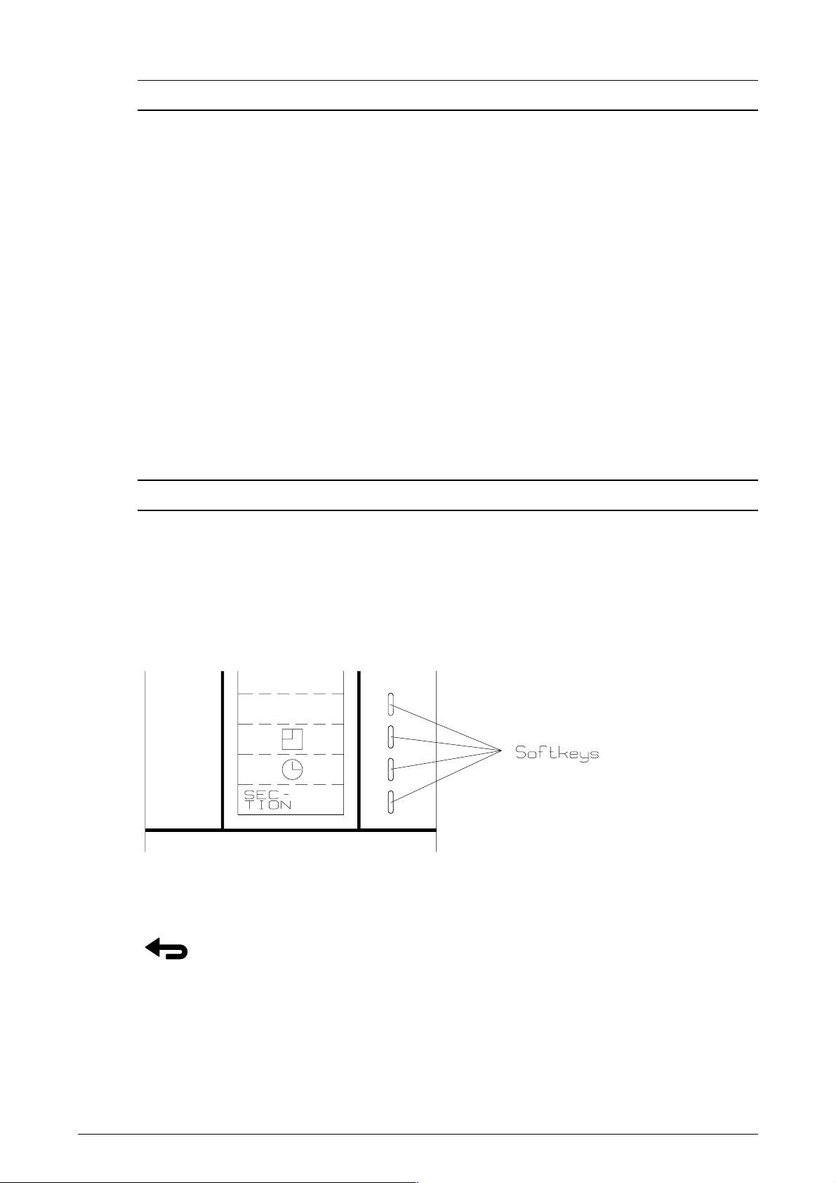
FUNCTION KEYS (SOFTKEYS)
Operation of the LH 965 is very simple with the 4 function keys (softkeys) to the
right of the display - the four keys are each marked with a white vertical dash. The
present function of these keys is displayed to the left of the key. When a key is
pressed the 4 function keys can change into a new function (see ill.).
RETURN KEY
LH A
GRO 5
This key is used if you want to return to a previous
menu/function. One “page” (picture) is changed each
time the key is pressed. The key is also used to
accept a RPM warning if it does not require a stop.
Page 6

LH 965 O
PERATORS MANUAL
RPM CONTROLS
When you press this key the speed in RPM of the
following 6 shafts is shown, irrespective of which
function is selected:
1. CYLINDER
2. STRAW WALKER
3. CHOPPER
4. FAN
5. GRAIN ELEVATOR
6. RETURN ELEVATOR
A warning can be encoded for each of the above
shafts. This is done in the ENCODE MENU
(described on page 12).
ZOOM-PICTURES
CONTRAST
The primary function of the computer is to show grain
loss. In normal operation it is therefore possible to
make the bars bigger with the zoom key. Press the
zoom-key and the function keys will disappear.
You return to the previous picture by pressing the
return key.
By pressing this key the contrast of the display
(bright/dark) can be adjusted. This ensures optimum
contrast in all conditions.
NOTE: In extreme cold or heat the screen may
become blank or black. It may be possible to
compensate for this with the ”CONTRAST
KEY”, but the display will return to normal
when the temperature is between -10 degrees
C and + 60 degrees C.
At the top of the picture a counter is shown.
Normal contrast is 45 - 50.
Contrast + = darker display
Contrast - = brighter display
Press the ”DELETE KEY" to get back to normal
value.
6 LH A
GRO
Page 7

KEY
LH 965 O
This key has no function with the LH 965.
PERATORS MANUAL
DELETE KEY
BACKGROUND LIGHT
NUMERIC KEYS
0 - 9
The delete key is used together with the numeric keys
when encoding. It deletes the chosen value.
Is used to switch the background light on and off.
This can, however, also be done in the ”CONTRAST
FUNCTION”.
The background light is always off, when the
computer is switched on.
Used only for encodings.
Besides the previously mentioned RPM warnings there are also warnings for the
following:
Picture Description
Full grain tank.
Too much grain loss, when the grain warning is ON.
Besides the following will be shown:
Picture Description
Area counter stopped.
Reduced cutter bar width.
LH A
GRO 7
Page 8

LH 965 O
PERATORS MANUAL
MAIN MENU
You reach the main menu by pressing the RETURN key until the following reading
is shown:
In this menu you can choose:
OPERATION normal use of the computer.
ENCODE new encodings or change of the
encoded values.
DATA/DELETE to read or delete/clear data.
TEST to test the system/sensors.
Select the required function by pressing the function
key to the right of the required function.
OPERATION
When this function has been selected, an optional
information is displayed at the top. However, the first
time the function is selected, speed will always be
shown. The function to show is selected with the 4
function keys.
Next two bars show the loss for straw walkers ( )
and sieves ( ). This reading is the most
important and it therefore uses a relatively large
amount of space. The “ZOOM” key can further
enlarge the bars.
Between the two bars, Ha area override status, full
grain tank, too much loss and reduced cutter bar
width (section) are shown.
Below the grain loss reading the present function of
the 4 function keys is shown.
The options of the function keys are as follows:
8 LH A
GRO
Page 9

1: AREA FUNCTIONS
LH 965 O
PERATORS MANUAL
HA/T: Efficiency: The size of the area worked
per hour with the present speed.
HA: Area counter. The size of the area
worked since the counter was cleared.
The counter can be cleared in the
DATA/DELETE function where there
also is a total counter for area.
HA LEFT: If before start the size of the field has
been encoded (in ENCODE) the
remaining area can be read here at any
time.
SECTIONS: Each time this key is pressed the
harvest width is reduced with 1/4,
irrespectively of the encoded working
width. The reduction will affect the area
counting and the grain loss calculation.
Each time the cutter bar is raised and
is shown on the display the
harvest width will automatically be
changed into full width.
LH A
GRO 9
Page 10

LH 965 O
PERATORS MANUAL
2: TIME FUNCTIONS
TIMER: This function is used to measure the
time consumption for a certain piece of
work. The timer can be manually started
and stopped when the function is
selected. The counter can be cleared in
DATA/DELETE where there also is a
total counter for time consumption.
NOTE: Not controlled by the override
sensor.
END TIME: This function shows the time when the
job will be finished. The time is
calculated on the basis of the present
efficiency and the remaining area.
Works only if HA LEFT is encoded.
CLOCK: Time in hours:minutes:seconds. Time is
set in ”ENCODE”.
DATE: Date appears as day:month:year. Date
is set in ”ENCODE”.
10 LH A
GRO
Page 11

LH 965 O
PERATORS MANUAL
ENCODE
When having selected this function set the following encode options appear. The
encode procedure of the individual values will be described later.
When you want to make an encodement, the cursor (the dark bar) is set on the
required function by using the arrow keys and then press SELECT.
Press the NEXT PAGE key to reach the next “page” (reading).
LOSS ADJUST
This function is used to adjust the grain loss to a
correct level (50% of max. deflection). The
adjustment is to made while driving. First a normal
adjustment of the combiner is made. When the
maximum speed with an acceptable grain loss has
been reached the reading is set at this speed by
using the function keys.
Above each of the bars there is a counter so that you
can write down the basic setting for each cereal. This
will ease the setting when changing from one cereal
into another. However, the setting should be checked
in connection with any cereal change.
LH A
GRO 11
Page 12

LH 965 O
PERATORS MANUAL
WHEEL CIRCUMFERENCE
Here the wheel circumference of the combine harvester wheel at which the speed
transmitter is mounted is to be encoded. If several magnets are mounted on the
wheel; the wheel circumference must be divided by the number of magnets before
encodement.
HOW TO MEASURE THE WHEEL CIRCUMFERENCE:
1. Make a mark on the ground and on the tyre.
2. Make 10 revolutions with the wheel.
3. Mark out on the field again.
4. Measure the distance between the two marks and divide the result by 10. The
result is the effective wheel circumference. (Wheel circumference must be
encoded in cm. i.e. 2,53 is encoded as 253).
5. The measured effective wheel circumference is to be divided by the number of
magnets.
NOTE: When counting the wheel revolutions make sure this is done for the
wheel on which the magnets are mounted.
WORKING WIDTH
Here the effective working width of the cutter bar in centimetres is to be encoded
(width minus over-laps).
LOSS WARNING
Here you can choose to have a warning for an
unacceptably large grain loss. If the warning is ON it
will be activated at 75% reading. The warning is given
in the form of a flashing reading and an acoustic
alarm. It is possible to encode a delay of 0 - 10
seconds for the acoustic alarm so that a brief exceed
of the warning limit will cause no warning.
12 LH A
GRO
Page 13

LH 965 O
PERATORS MANUAL
HA REST
Here the size of the field is to be encoded before start. From this encodement the
endtime will also be calculated.
DATE-TIME
Here the following is set/encoded:
HOURS-MINUTES-SECONDS-YEAR-MONTH-DAY.
THRESHER WARNING
Here you choose if the thresher warning is ON or
OFF. If you want to control the revolutions, the
accepted minimum RPM for the shaft must be
encoded. The present RPM appears on the display
as a help in connection with the encode.
The warning is given with an acoustic alarm and a
warning picture on the display showing which shaft is
causing the warning and the RPMs of the shaft.
The warning picture stays on until the revolutions are
over the warning limit. If the warning is not so serious
that it requires a stop, the warning can be stopped by
pressing the RETURN key, but please note: the
shaft is no longer controlled if the warning has
been stopped with the RETURN key and there will
be no further warnings before the revolutions
have been over the warning limit again or the
computer has been switched off.
STRAW WALKER WARNING
The encodement of warning for straw walker works like THRESHER WARNING.
See above.
CHOPPER WARNING
Encodement of warning for straw chopper works like THRESHER WARNING. See
above.
FANS WARNING
Encodement of warning for van works like THRESHER WARNING. See above.
LH A
GRO 13
Page 14

LH 965 O
PERATORS MANUAL
GRAIN ELEVATOR WARNING
Encodement of warning for grain elevator works like as THRESHER WARNING.
See above.
RETURN ELEVATOR WARNING
Encodement of warning for return elevator works like THRESHER WARNING.
See above.
DATA/DELETE
When this function set has been selected the below
reading will appear. It contains both trip and a total
counter. The total counters are only in this function
and are marked with a +.
Clearing the trip counters is done by pressing the
DELETE TRIP key. Both trip counters are cleared at
the same time. The DELETE TRIP key can be used
no matter where the cursor is.
Clearing the total counters is done by pressing the
DELETE key. The total counters are cleared one by
one by placing the cursor on the wanted counter and
pressing DELETE.
14 LH A
GRO
Page 15

LH 965 O
PERATORS MANUAL
TEST
When this function set has been selected the following pictures will appear.
You can change between the display pictures with the function key NEXT PAGE.
The TEST-function is used to test the mounted sensors. For each sensor a
counter shows how many times the sensor has been activated. This counter is to
the left on the display under each sensor.
All counters are cleared simultaneously by the DELETE key.
The counters can count up to 255 pulses. After this they will restart from 0.
To the right you can see if the sensor is active (LO) or not (HI).
LH A
GRO 15
Page 16

LH 965 O
PERATORS MANUAL
NOTES
16 LH A
GRO
 Loading...