

Page 1

OPERATORS MANUAL
FOR THE
LH 85 – SPRAY CONTROLLER
LH. No. 020-851-UK Version 1.00
LH Technologies Denmark ApS
Mølhavevej 2
9440 Aabybro
Denmark
Tlf. +45 9696 2500
Fax. +45 9696 2501
Internet: http://www.lh-agro.com/
Page 2

Page 3

Introduction
INTRODUCTION ..............................................................................................................1.3
Page 4

I
NTRODUCTION
We have endeavoured to deliver a fault free product. To ensure optimal use of the
equipment we ask that great attention be paid when reading the manual. We are
more than happy to help should any queries arise, both when the product is used
for the first time and at any later date. Regarding responsibility for use of the
product, we refer to our sales and delivery terms especially paragraph 7, which
follows:
7. Product usage.
7.1 Any use of the product is at the sole risk of the buyer. The buyer is
7.2 When implementing any new equipment the buyer must take great care and pay
O
therefore not entitled to any form for compensation caused by, for example,
any of the following:
Disturbance to/from any electronic services or products that do not
confirm to the standards for CE marking,
Missing or poor signal coverage or a succession hereof from external
transmitters/receivers, used by the buyer,
Functional faults, which apply to or from a PC-program or PC-equipment,
not delivered by the seller,
Faults that may arise from the buyers negligence to react to warnings
and fault messages from the product, or which can be traced to
negligence and/or absent constant control of the work carried out in
comparison to the planned job.
attention. Any doubts as to correct operation/use should result in
contacting the sellers service department.
PERATORS MANUAL FOR THE LH 85 SPRAY CONTROLLER
This manual may not be altered, copied or manipulated in any way. Unoriginal
manuals can lead to operational faults damaging machines or crops as a
consequence thereof. LH Technologies Denmark ApS can therefore not be held
responsible for damages incurred, which can be traced to the use of unoriginal or
manipulated manuals. Original manuals can be requisitioned at any time from your
dealer.
With regards
LH Technologies Denmark ApS
Mølhavevej 2
9440 Aabybro
Denmark
Tel. +45 96 96 25 00
Fax. +45 96 96 25 01
Internet: http://www.lh-agro.com/
1.2 LH
AGRO
Page 5

O
PERATORS MANUAL FOR THE LH 85 SPRAY CONTROLLER
INTRODUCTION
The LH 85 Spray Controller is not only a powerful spray rate controller, but also a
command centre for the whole sprayer!
Whilst designing this unit we have tried hard to ensure that operation is as simple
as possible, the ergonomically designed housing and the menu based operating
system ensure that the unit will be a pleasure to use for many years.
A large amount of the system is built up around easily understood icons and
instructions on the display in clear text make this operator's manual almost
redundant, however we recommend that this manual be used as a reference for
the many functions available.
Despite the fact that this manual is large and may, upon first impressions, seem to
be too much to read, we ask you to study at least chapter 2 where the basic
functions of the system are explained.
I
NTRODUCTION
Examples are used throughout this manual to ensure that finding a solution to any
problems that might arise can be solved simply by changing the values in the
examples with the values required for the task in hand.
Our experience tells us that it is a good idea to familiarise yourself with the system
before the first day of use thus avoiding delays in getting the job done!
Please keep this operator's manual within easy reach and together with the LH 85.
LH
AGRO
1.3
Page 6

I
NTRODUCTION
O
PERATORS MANUAL FOR THE LH 85 SPRAY CONTROLLER
1.4 LH
AGRO
Page 7

General operation
OPERATING THE LH 85 SPRAY CONTROLLER ...........................................................2.2
THE SPRAY CONTROLLER SYSTEM OUTLINE ...................................................2.2
CONTROLLER SECTION (A) .............................................................................. 2.3
SWITCH SECTION (B) ........................................................................................2.3
SWITCH SECTION OVERVIEW .............................................................................. 2.4
POWER ON/OFF SWITCH (POS. B1)................................................................. 2.4
AGITATION SWITCH (POS.B2) ..........................................................................2.4
FILL FUNCTION SWITCH (POS. B3) .................................................................. 2.4
AUTOMATIC/MANUAL FUNCTION SWITCHES (POS. B4 & B5).......................2.4
MAIN ON/OFF SWITCH (POS. B6) .....................................................................2.4
SWITCHES C1 TO C9 ......................................................................................... 2.4
SWITCHES D1 TO D9 ......................................................................................... 2.4
CONTROLLER OVERVIEW ............................................................................................. 2.5
DISPLAY (POS. A1)............................................................................................. 2.5
SETUP KEY (POS. A2)........................................................................................ 2.6
INFO KEY (POS. A3) ........................................................................................... 2.6
JOB KEY (POS. A4)............................................................................................. 2.7
ESCAPE KEY (POS. A5) .....................................................................................2.7
ARROW KEYS (POS. A6, A8, A9, A10) ..............................................................2.7
ENTER KEY (POS. A7) .......................................................................................2.7
CLEAR KEY (POS. 11) ........................................................................................ 2.7
FUNCTION KEY 1 (POS. A12) ............................................................................2.7
FUNCTION KEYS 2 & 3 (POS. A13 & A14)......................................................... 2.8
FUNCTION KEY 4 (POS. A15) ............................................................................2.8
NAVIGATING THROUGH THE MENUS...........................................................................2.9
SELECTING AN ITEM FROM A MENU AND ALTERING A VALUE........................ 2.9
SELECTING A VALUE FROM A LIST (CHECKBOXES) .......................................2.12
Page 8
G
ENERAL OPERATION
O
PERATORS MANUAL FOR THE LH 85 SPRAY CONTROLLER
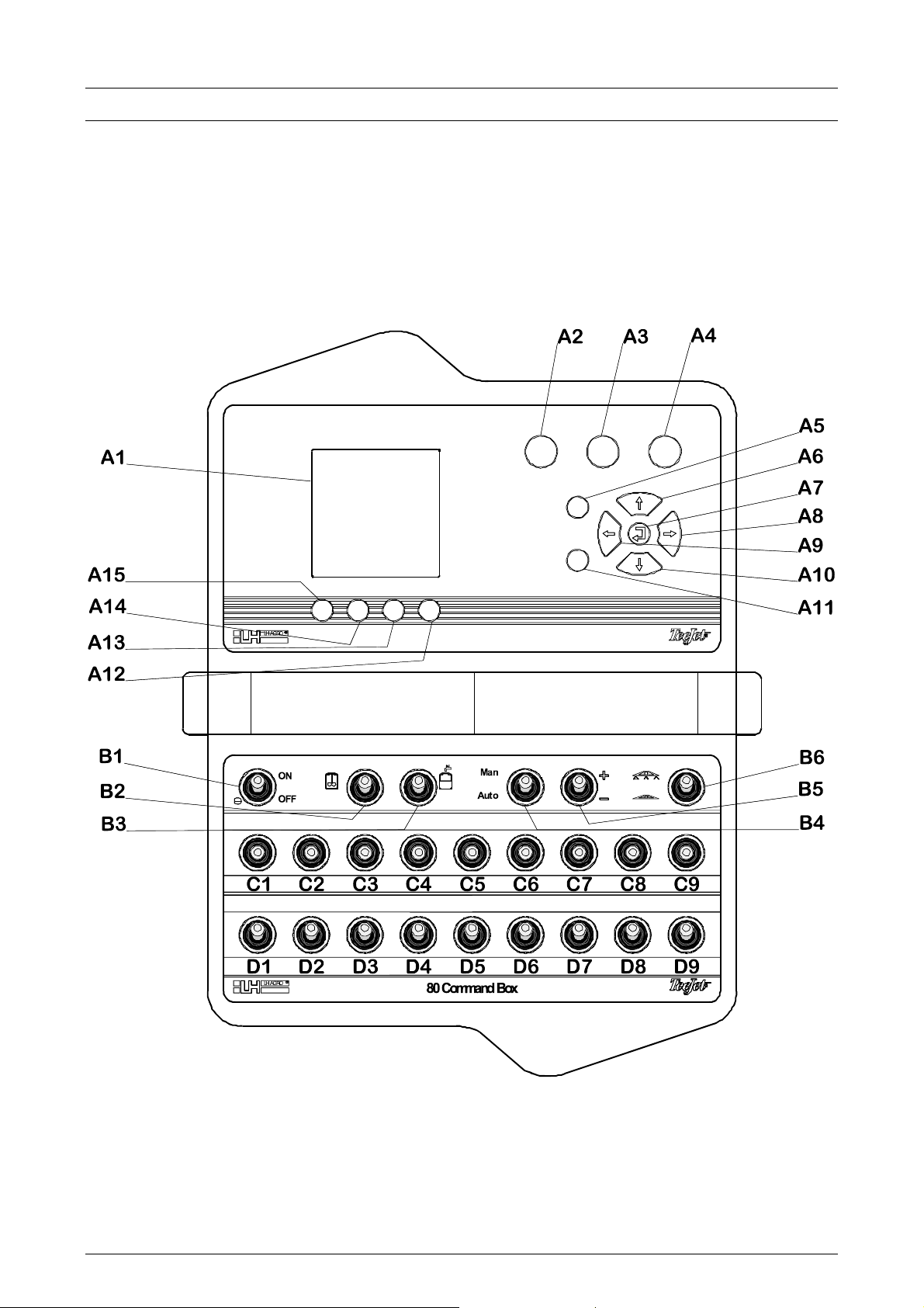
OPERATING THE LH 85 SPRAY CONTROLLER
The LH 85 spray controller system can be split into two sections:
The controller section (A)
The switch section (B, C & D)
THE SPRAY CONTROLLER SYSTEM OUTLINE
2.2 LH
AGRO
Page 9
O
PERATORS MANUAL FOR THE LH 85 SPRAY CONTROLLER
CONTROLLER SECTION (A)
Pos. Description Pos. Description
A1 Display A9 Left function key
A2 Setup key A10 Down function key
A3 Info key A11 Clear key
A4 Job key A12 Function key 1
A5 Escape key A13 Function key 2
A6 Up function key A14 Function key 3
A7 Enter key A15 Function key 4
A8 Right function key
SWITCH SECTION (B)
G
ENERAL OPERATION
Pos. Description Pos. Description
B1 Power on/off switch B4 Auto/man function switch
B2 Agitation switch B5 Rate increase/decrease
B3 Fill function switch B6 Main on/off
Pos. Description
C1 – C9 Switch row C (functions depend on model)
D1 – D9 Switch row D (functions depend on model)
LH
AGRO
2.3
Page 10

G
ENERAL OPERATION
O
PERATORS MANUAL FOR THE LH 85 SPRAY CONTROLLER
SWITCH SECTION OVERVIEW
POWER ON/OFF SWITCH (POS. B1)
This switch is used to switch the system on and off.
AGITATION SWITCH (POS.B2)
This switch is used to switch the tank agitation on and off (if tank agitation is fitted).
FILL FUNCTION SWITCH (POS. B3)
At present this switch has no function.
AUTOMATIC/MANUAL FUNCTION SWITCHES (POS. B4 & B5)
The AUTO/MAN switch is used to change between automatic and manual spray
rate control.
When this switch is in the "MAN" position (up) the spray rate can be controlled
thus:
• The spray rate is increased by holding the RATE INCREASE/DECREASE
switch up.
• The spray rate is decreased by holding the RATE INCREASE/DECREASE
switch down.
When this switch is in the "AUTO" position (down) the spray rate is controlled
automatically by the computer.
MAIN ON/OFF SWITCH (POS. B6)
The main on/off switch is used to switch the main boom on & off.
• When the switch is in the up position the sprayer is on.
• When the switch is in the down position the sprayer is off.
The individual boom sections are typically switched on and off with the switches
D1 to D9 depending on the LH 85 spray controller model.
SWITCHES C1 TO C9
The function for the switches in this row depends on the sprayer.
SWITCHES D1 TO D9
The function for the switches in this row depends on the sprayer.
2.4 LH
AGRO
Page 11
O
PERATORS MANUAL FOR THE LH 85 SPRAY CONTROLLER
CONTROLLER OVERVIEW
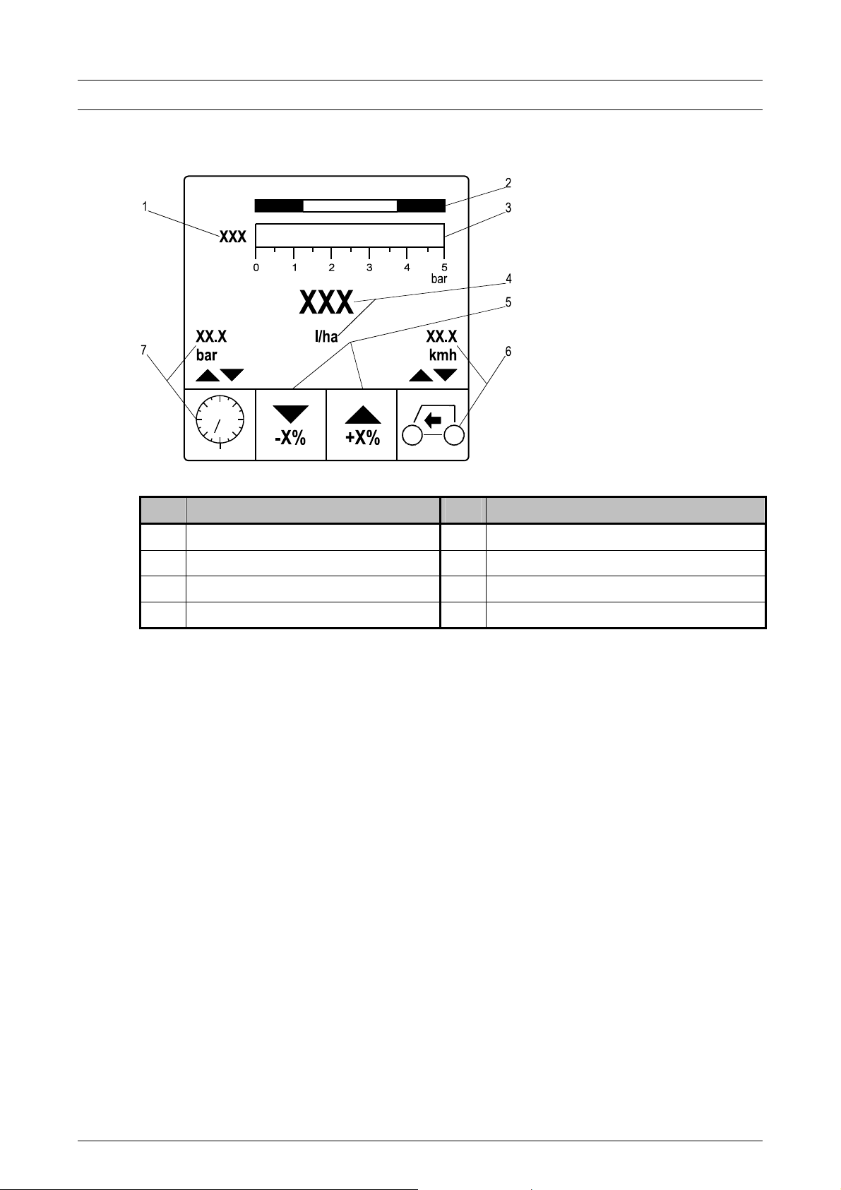
DISPLAY (POS. A1)
G
ENERAL OPERATION
Pos. Description Pos. Description
1 Selected nozzle type 5 Boost or manual +/-
2 Optimum pressure range 6 User selectable work information
3 Working pressure indicator 7 User selectable spray information
4 Application rate
Selected nozzle type (pos. 1):
The nozzle type selected is displayed here.
Optimum pressure range (pos. 2):
The optimum working pressure range for the selected nozzle type is shown here.
Working pressure indicator (pos. 3):
The current working pressure is shown. The range of the pressure indicator
changes to suit, e.g. the selected nozzle type, working speed range, etc.
LH
Application rate (pos. 4):
The actual application rate shown in litres per hectare. The target rate is shown
when the main on/off switch (B6) is in the off position.
AGRO
2.5
Page 12
G
ENERAL OPERATION
Boost or manual +/- (pos. 5):
The function of these keys may change depending on whether automatic or
manual rate control is selected in the "Fast setup" menu. See page 3.4
Increase or decrease the required application rate in steps using the function keys
(A13 & A14). See page 2.8.
The size of the steps (percent of current rate) is encoded under MACHINE SETUP
under "Boost" (see page 4.11).
When manual rate control has been selected from the "Fast setup" menu the
function of the keys changes to manual rate increase (+) and manual rate
decrease (-).
User selectable work information (pos. 6):
It is possible to select which work related information is displayed by pressing
function key 1 (A12).
A description of the work related information that can be displayed can be seen on
page 3.2.
O
PERATORS MANUAL FOR THE LH 85 SPRAY CONTROLLER
User selectable spray information (pos. 7):
It is possible to select which spray related information is displayed by pressing
function key 4 (A15).
A description of the spray related information that can be displayed can be seen
on page 3.2.
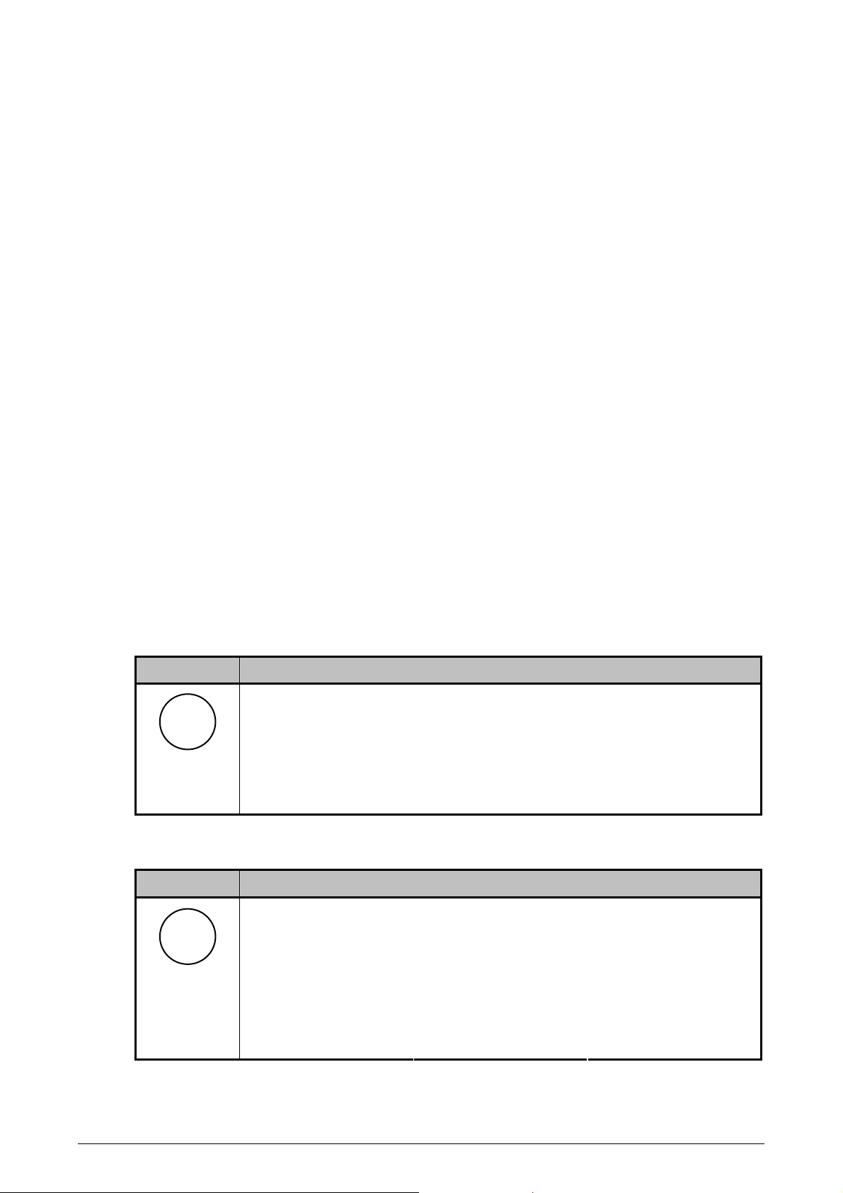
SETUP KEY (POS. A2)
Key Description
The SETUP key is used to enter the setup menus.
Setup
If the main on/off switch (B6) is in the on position the "Fast setup"
menu is displayed (see page 3.4).
If the main on/off switch (B6) is in the off position the main setup
menu is shown. A description of the available settings can be seen
in the "Encode" chapter of this operators manual.
INFO KEY (POS. A3)
Key Description
Pressing the INFO key displays the following information (use the
Info
up & down arrow keys (A6 & A10) to highlight and the ENTER key
(A7) to select. A detailed description of each function can be seen
on page 3.3:
• Controller • Counters • Export/Import
• Diagnostics • Alarm log • Active alarms
2.6 LH
AGRO
Page 13
O
PERATORS MANUAL FOR THE LH 85 SPRAY CONTROLLER
JOB KEY (POS. A4)
Key Description
The JOB key is used for the task function. A description of the task
Job
function can be seen on page 5.1.
ESCAPE KEY (POS. A5)
Key Description
G
ENERAL OPERATION
Esc
saving any alterations.
ARROW KEYS (POS. A6, A8, A9, A10)
Key Description
The ESCAPE key is used to return to the previous menu without
The arrow keys are used to select and alter an encodement.
When encoding a value the arrow keys are used to select and
adjust the digit that needs changing.
Each digit can be set from 0 to 9 with the ARROW UP/DOWN keys.
The ARROW RIGHT/LEFT keys are used to select the digit to be
altered.
ENTER KEY (POS. A7)
Key Description
The enter key is used to accept settings and to return to the
previous screen.
CLEAR KEY (POS. 11)
Key Description
The clear key is used to reset settings/counters and to accept
C
warnings.
FUNCTION KEY 1 (POS. A12)
Key Description
Key 1
Pressing this key during operation pages through and selects the
user selectable work related information to be shown on the display.
A description of the work related information that can be displayed
can be seen on page 3.2.
LH
AGRO
2.7
Page 14
G
ENERAL OPERATION
O
FUNCTION KEYS 2 & 3 (POS. A13 & A14)
Key Description
The function of these keys may change depending on whether
automatic or manual rate control is selected in the "Fast setup"
Keys 2 & 3
menu. See page 3.4
Increase or decrease the required application rate in steps using
these function keys.
When manual rate control has been selected from the "Fast setup"
menu the function of the keys changes to manual rate increase (+)
and manual rate decrease (-).
FUNCTION KEY 4 (POS. A15)
Key Description
Pressing this key during operation pages through and selects the
Key 4
user selectable spray related information to be shown on the
display.
A description of the spray related information that can be displayed
can be seen on page 3.2.
PERATORS MANUAL FOR THE LH 85 SPRAY CONTROLLER
2.8 LH
AGRO
Page 15
O
PERATORS MANUAL FOR THE LH 85 SPRAY CONTROLLER
G
NAVIGATING THROUGH THE MENUS
The LH 85 Spray controller uses a menu based structure for most functions.
Navigation through the menus is simple and unified throughout the whole
programme.
SELECTING AN ITEM FROM A MENU AND ALTERING A VALUE
The procedure to select and alter a setting in the LH 85 Spray controller is simple
and requires very little practice.
The procedure to navigate, select and alter a setting is best illustrated with an
example, which follows:
Step Key Action
To alter the nozzle configuration for a programmable nozzle (P1).
ENERAL OPERATION
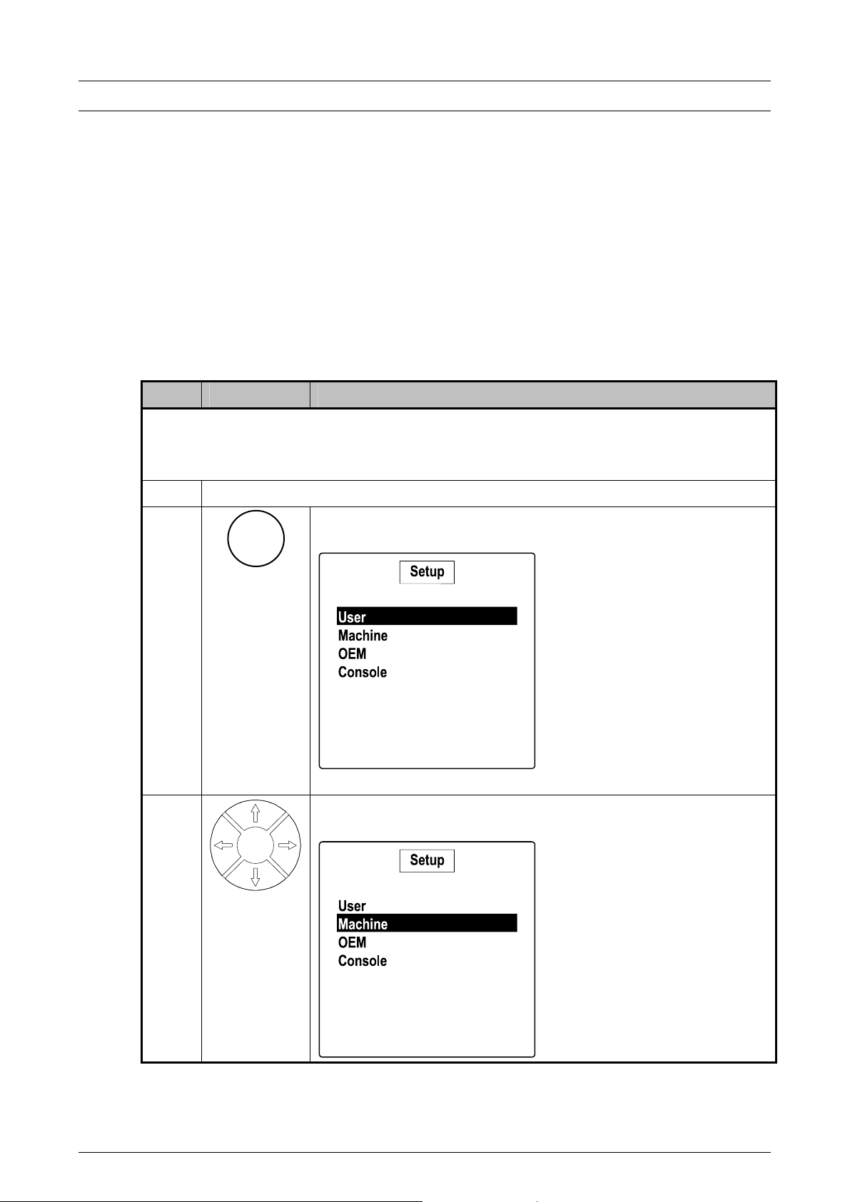
1 Switch the main on/off switch (pos. B6) to the OFF position (down).
2
Setup
Press the SETUP key and the following is shown in the
display:
3
Press the ARROW DOWN key to move the cursor to
"Machine"
LH
AGRO
2.9
Page 16
G
ENERAL OPERATION
Step Key Action
O
PERATORS MANUAL FOR THE LH 85 SPRAY CONTROLLER
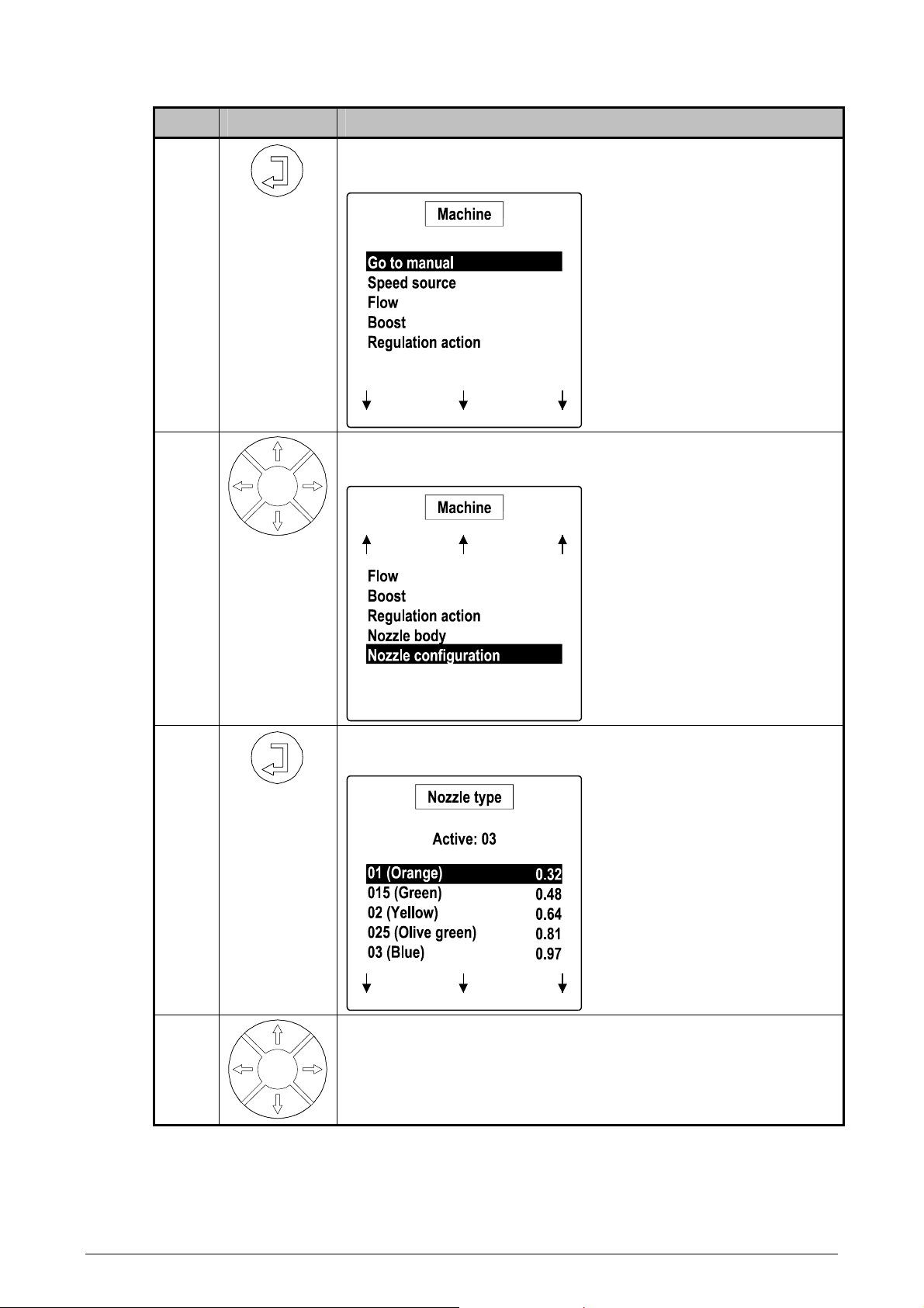
4
5
Press the ENTER key to select "Machine" and the first 5
available settings are shown in the display.
Notice the 3 arrows pointing
down at the bottom of the
display.
This indicates that further
menu items are available on
another page.
Press the ARROW DOWN key 6 times to highlight "Nozzle
configuration".
Notice the 3 arrows pointing
up at the top of the display.
This indicates that further
menu items are available on
another page.
6
7
Press the ENTER key to select "Nozzle configuration" and
the available settings are shown:
Repeatedly press the ARROW DOWN key until "P1" is
highlighted.
2.10 LH
AGRO
Page 17
O
PERATORS MANUAL FOR THE LH 85 SPRAY CONTROLLER
Step Key Action
G
ENERAL OPERATION
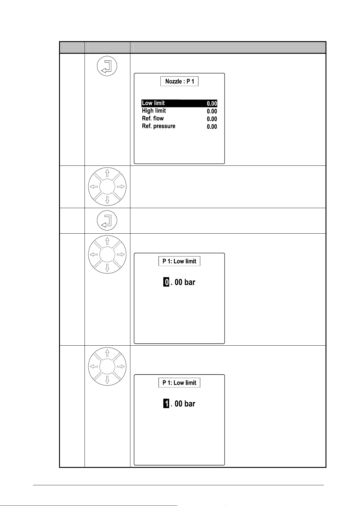
8
9
10
11
Press the ENTER key to select the configuration menu for
the selected nozzle.
Highlight the setting to be altered using the ARROW UP
and DOWN keys.
Press the ENTER key when the setting to be altered is
highlighted.
Highlight the digit to be altered by using the ARROW LEFT
and RIGHT keys.
12
Using the ARROW UP and DOWN keys change the digit to
the required value.
To reset a value simply press the C key.
LH
AGRO
2.11
Page 18
G
ENERAL OPERATION
Step Key Action
O
PERATORS MANUAL FOR THE LH 85 SPRAY CONTROLLER
13
Press the ENTER key to store the value and return to the
previous screen.
14
Esc
or
Repeat steps 9 to 13 until all of the required changes have
been made.
Then press the ESCAPE key to return to the previous
menu or press the SETUP key to return to the main menu
Setup
or press the JOB key to return directly to the main
operating screen.
or
Job
SELECTING A VALUE FROM A LIST (CHECKBOXES)
Some settings have a list of options to select from. The procedure for selecting the
required setting is similar to the above; a checkbox is used instead of a numerical
value.
An example follows:
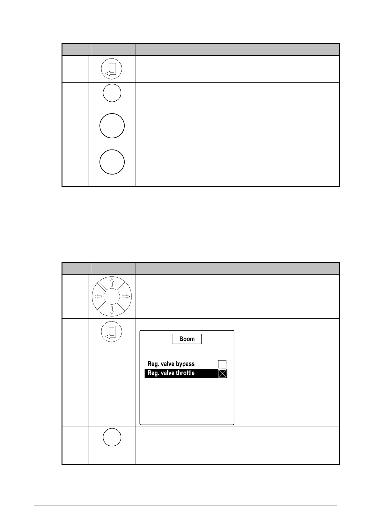
Step Key Action
1
Highlight the setting to be selected using the ARROW UP
and DOWN keys.
2
Press the ENTER key to select the option.
3
Esc
Then press the ESCAPE key to return to the previous
menu or press the SETUP key to return to the main menu
or press the JOB key to return directly to the main
operating screen.
2.12 LH
AGRO
Page 19

Operation
OPERATION.....................................................................................................................3.2
USER SELECTABLE SPRAY RELATED INFORMATION.......................................3.2
USER SELECTABLE WORK RELATED INFORMATION........................................3.2
INFO MENU .............................................................................................................3.3
FAST SETUP MENU................................................................................................ 3.4
GO TO MANUAL..................................................................................................3.5
SPEED SOURCE................................................................................................. 3.5
REGULATION BASE ...........................................................................................3.6
BACKLIGHT.........................................................................................................3.6
Page 20

O
PERATION
O
PERATORS MANUAL FOR THE LH 85 SPRAY CONTROLLER
OPERATION
All settings should be encoded/checked before any spray work commences.
Please refer to the SETTINGS section of this manual for a description of the
available settings.
USER SELECTABLE SPRAY RELATED INFORMATION
Symbol Description
Working pressure: The current working pressure shown as bar.
Flow rate: The present flow rate shown in litres per
Sprayed volume: The amount sprayed since the task was
Volume left: The amount remaining for the present field
Density: The density of the liquid being used.
hour.
started or since the counter was reset.
or task.
USER SELECTABLE WORK RELATED INFORMATION
Symbol Description
Forward speed: The present forward speed shown as
Working width: The present working width shown as
Area covered: The total area covered shown as hectares
Area left: The area that can be covered with the
Work efficiency: The present work efficiency shown as
kilometres per hour.
metres.
with 2 decimals since the task was started
or since the counter was reset.
Area is only measured when the sprayer is
in work.
current tank content.
This calculated figure is based on the
present volume in the tank, the actual
application rate and the current working
width.
hectares per hour.
This calculated value is based on the actual
forward speed and the present working
width.
3.2 LH
AGRO
Page 21
O
PERATORS MANUAL FOR THE LH 85 SPRAY CONTROLLER
Symbol Description
Distance covered: The distance covered shown as metres
Distance left: The distance that can be covered with the
Elapsed time: The time passed since the task was started
Wind speed: The current wind speed shown in metres
O
PERATION
since the task was started or since the
counter was reset.
Distance is only measured when the sprayer
is in work.
current tank content.
This calculated figure is based on the
present volume in the tank, the actual
application rate and the current working
width
or since the counter was reset.
Time is only measured when the sprayer is
in work.
per second.
This function is only possible when the main
on/off switch is in the off position and the
forward speed = 0 and if the system is fitted
with an anemometer.
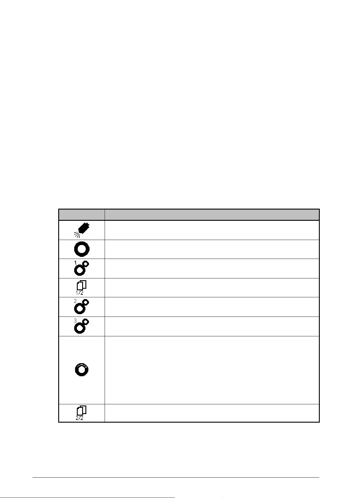
INFO MENU
Pressing the INFO key displays the following menu structure.
Each item in the menu is described in the following:
LH
AGRO
3.3
Page 22

O
PERATION
O
PERATORS MANUAL FOR THE LH 85 SPRAY CONTROLLER
Controller:
Selecting controller displays the hardware Id and part number of the LH 85 Spray
controller.
Counters:
There are three counter sets available in the LH 85 Spray controller. A brief
description can be seen in the following, for a more detailed description please see
the "Job Function" section of this manual (page 5.1):
Jobs: Each of the 16 jobs can be viewed, stored or cleared
individually.
Campaign: A total counter for, e.g. the season. The campaign counters
can be viewed, stored or cleared. A password is required to
clear the campaign counter.
Total: Data is constantly added to the total counter. The total
counter can be viewed, stored or cleared. A password is
required to reset the total counter.
Import/Export:
This menu item currently has no function.
Diagnostics:
Should problems arise with the system the inputs and outputs of the LH 85 Spray
controller can be tested using this menu item.
Please refer to the "System" section of this manual (page 6.1) for a description of
the various inputs and outputs.
Alarm log:
This menu item currently has no function.
Active alarms:
This menu item currently has no function.
FAST SETUP MENU
When the system is in work (spraying) pressing the SETUP key selects the "Fast
Setup" menu.
The settings in this menu are directly related to spray work and allow the available
settings to be altered whilst spraying.
Each item in the menu is described in the following:
3.4 LH
AGRO
Page 23
O
PERATORS MANUAL FOR THE LH 85 SPRAY CONTROLLER
GO TO MANUAL
Using this function it is possible to change from automatic rate control to manual
rate control and back to automatic rate control again.
The function of the boost keys (pos. A13 & A14) changes to manual
increase/decrease when manual rate control is selected and the rate can be
altered using these keys.
• Pressing the + key increases the rate.
• Pressing the – key decreases the rate.
To return to automatic rate control again simply press the SETUP key and select
"Go to automatic"
SPEED SOURCE
It is possible to change the sensor, from which the forward speed signal is
received and used for regulation, during operation by using this function.
This function can be used when, e.g. different wheels are used on the implement.
O
PERATION
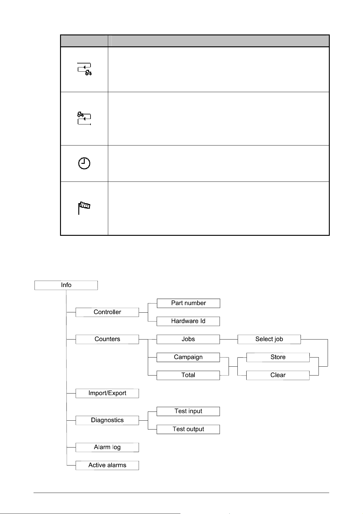
A description of the available forward speed inputs can be seen in the following:
Symbol Description
Radar Pressing this key selects a signal from a
radar sensor.
Tractor wheel Pressing this key selects a signal from a
sensor fitted to the tractor.
Implement wheel 1 Pressing this key selects a signal from a
sensor fitted to the implement.
Pressing this key will show the next page and display the
following
Implement wheel 2 Pressing this key selects a signal from a
sensor fitted to the implement.
Implement wheel 3 Pressing this key selects a signal from a
sensor fitted to the implement
Simulated speed Pressing this key selects simulated forward
speed. When simulated speed has been
selected function keys 2 & 3 (pos. A13 &
A14) will allow the speed to be increased or
decreased.
The speed to be simulated is encoded in the
"Machine setup" menu under "Speed
source" (page 4.8).
LH
Pressing this key will show the first page
For correct operation the speed signal sources to be used must be
calibrated accurately. The procedure for forward speed calibration can be
seen on page 4.5.
AGRO
3.5
Page 24

O
PERATION
O
REGULATION BASE
This menu item might not appear depending on model/settings.
If the system is fitted with a pressure senor and a flowmeter it is possible to select
which sensor should be used for measuring flow (and thus for rate control).
The following options are available:
Symbol Description
PERATORS MANUAL FOR THE LH 85 SPRAY CONTROLLER
Flowmeter Pressing this key selects flow based
regulation.
Pressure sensor Pressing this key selects pressure based
regulation.
Auto When this key is pressed the LH 85 Spray
controller selects which flow input to be
used based on the minimum flow setting for
the flowmeter.
BACKLIGHT
The contrast and backlight settings for the display can be adjusted during
operation. Please refer to "Contrast/Light" on page 4.24 in the SETTINGS section
of this manual for detailed information.
3.6 LH
AGRO
Page 25

Settings
USER SETUP...................................................................................................................4.3
JOB ..........................................................................................................................4.4
TANK FILLING .........................................................................................................4.4
TANK LEVEL .......................................................................................................4.4
TRANSMIT...........................................................................................................4.4
MACHINE SETUP ............................................................................................................4.4
GO TO MANUAL......................................................................................................4.5
SPEED SOURCE.....................................................................................................4.5
SPEED SENSOR SELECTION AND CALIBRATION ..........................................4.6
SIMULATED SPEED ...........................................................................................4.8
FLOW.......................................................................................................................4.9
AUTOMATIC FLOWMETER CORRECTION .....................................................4.10
MANUAL FLOWMETER CORRECTION ...........................................................4.11
BOOST................................................................................................................... 4.11
REGULATION ACTION .........................................................................................4.11
FAST REGULATION VALUE ............................................................................. 4.11
PRECISE REGULATION VALUE ......................................................................4.12
NOZZLE BODY ...................................................................................................... 4.12
NOZZLE CONFIGURATION ..................................................................................4.13
OEM SETUP................................................................................................................... 4.15
UNIT.......................................................................................................................4.16
SENSORS..............................................................................................................4.16
PRESENCE .......................................................................................................4.16
CALIBRATION ...................................................................................................4.16
BOOM ....................................................................................................................4.19
BOOM SECTIONS.............................................................................................4.19
NOZZLES PER SECTION .................................................................................4.19
NOZZLE SPACING............................................................................................4.20
REGULATION VALVES.....................................................................................4.20
SECTION VALVES ............................................................................................4.20
REGULATION DETAILS....................................................................................4.20
TANK...................................................................................................................... 4.22
MAXIMUM TANK CONTENT ............................................................................. 4.22
AUTO FILLING...................................................................................................4.22
ELECTRIC AGITATION .....................................................................................4.22
MINIMUM TANK VOLUME ................................................................................4.22
AUTO FILLING OFFSET ...................................................................................4.22
ALARM CONFIGURATION.................................................................................... 4.22
MINIMUM TANK CONTENT ALARM.................................................................4.22
FLOW/PRESSURE CROSS-CHECK................................................................. 4.23
COMMUNICATION ................................................................................................ 4.23
MOTOR MANAGEMENT .......................................................................................4.23
Page 26

S
ETTINGS
O
PERATORS MANUAL FOR THE LH 85 SPRAY CONTROLLER
CONSOLE SETUP .........................................................................................................4.23
CONTRAST/LIGHT ................................................................................................ 4.24
LANGUAGE ...........................................................................................................4.24
DATE/TIME ............................................................................................................ 4.24
BUZZER................................................................................................................. 4.25
FILE SYSTEM ........................................................................................................ 4.25
4.2 LH
AGRO
Page 27

O
PERATORS MANUAL FOR THE LH 85 SPRAY CONTROLLER
USER SETUP
The settings in the USER setup menu are related to daily work. The procedure to
access the "User setup" menu is thus:
Step Key Action
1 Switch the main on/off switch (B6) to the off position.
S
ETTINGS
2
Setup
Press the SETUP key.
3
Highlight the "User" menu item using the ARROW UP and
DOWN keys.
4
Press the ENTER key to select.
The following diagram shows the menu structure of the "User" setup menu:
A description of each setting is described in the following:
LH
AGRO
4.3
Page 28

S
ETTINGS
O
JOB
For a detailed description of the "Job" menu item please see the JOB FUNCTION
section of this manual.
TANK FILLING
TANK LEVEL
Encode the actual tank content in litres.
This value is used for the following calculated information:
• Volume left.
• Area left.
• Distance left.
TRANSMIT
This menu item currently has no function.
PERATORS MANUAL FOR THE LH 85 SPRAY CONTROLLER
MACHINE SETUP
The "Machine" settings relate directly to settings that can differ from machine to
machine. The procedure to access the "Machine setup" menu is similar to the
procedure for accessing the "User setup" menu however the procedure is
described below:
Step Key Action
1 Switch the main on/off switch (B6) to the OFF position.
2
Setup
3
Press the SETUP key.
Highlight the "Machine" menu item using the ARROW UP
and DOWN keys.
4
Press the ENTER key to select.
4.4 LH
AGRO
Page 29

O
PERATORS MANUAL FOR THE LH 85 SPRAY CONTROLLER
Once selected, the following menu structure is available, a detailed description of
each setting can be seen after the diagram:
S
ETTINGS
Setup
Machine
OEM
Console
Go to manual
Speed source
Flow
Boost
Regulation action
Nozzle body
Nozzle configuration
Speed source
Simulated speedUser
Flow corr. automatic
Flow corr. manual
Boost percentage
Fast
Precise
Select nozzle body Select nozzle type
Select nozzle type
Select/Calibrate
On/Off - High/Low
Sprayed volume
Vol. From controller
Ta nk lev e l
Regulation value
Low limit
High limit
Ref. flow
Ref. pressure
GO TO MANUAL
This function is described under the "Fast setup" section on page 3.4.
SPEED SOURCE
The sensor to be used for forward speed and thus regulation can be selected and
calibrated here. It is also possible to simulate forward speed with the LH 85 Spray
controller, which is useful for, e.g. flowmeter calibration.
LH
AGRO
4.5
Page 30

S
ETTINGS
O
PERATORS MANUAL FOR THE LH 85 SPRAY CONTROLLER
SPEED SENSOR SELECTION AND CALIBRATION
Upon selecting this menu the following is displayed:
Pos. Description Pos. Description
1 Current calibration figure 4 Page key
2 Currently selected sensor 5 Function key 4 (select sensor)
3 Calibrate key 6 Function key 3 (select sensor)
The forward speed sensors available can be seen in the following:
Symbol Description
Radar Pressing this key selects a signal from a
radar sensor.
Tractor wheel Pressing this key selects a signal from a
sensor fitted to the tractor.
Pressing this key will show the next page and display the
following
Implement wheel 1 Pressing this key selects a signal from a
sensor fitted to the implement.
Implement wheel 2 Pressing this key selects a signal from a
sensor fitted to the implement.
Pressing this key will show the next page and display the
following
Implement wheel 3 Pressing this key selects a signal from a
sensor fitted to the implement
Pressing this key will show the first page
4.6 LH
AGRO
Page 31

O
PERATORS MANUAL FOR THE LH 85 SPRAY CONTROLLER
Automatic speed sensor calibration:
The procedure to calibrate the forward speed sensor follows:
Step Key Action
1 Measure and mark a 100 metre stretch in the field. Drive to
the start mark and stop.
When calibrating the forward speed sensor we recommend
doing so in the field with ½ the total volume in the tank to
ensure conditions as close to spray work as possible.
2 From the "Machine" setup menu select "Speed source".
3 From the "Speed source" menu select "Speed source" this
screen is shown in the display.
S
ETTINGS
4
Keys 3 & 4
Select the speed sensor to be calibrated by using function
keys 3 & 4 (pos. 5 & 6 in the above).
Use the page key (pos. 4 in the above) to view/select other
sensors.
5
Press the CALIBRATE key once.
6 Drive the 100 metre stretch – the controller will count the
number of pulses received whilst driving.
7 Stop exactly at the stop mark of the 100 metre stretch.
8
Press the ENTER key and the forward speed sensor has
been calibrated.
LH
AGRO
4.7
Page 32

S
ETTINGS
O
PERATORS MANUAL FOR THE LH 85 SPRAY CONTROLLER
Manual speed sensor calibration:
If the number of pulses received per driven 100 metres is known then this can be
encoded directly thus:
Step Key Action
1 From the "Machine" setup menu select "Speed source".
2 From the "Speed source" menu select "Speed source".
3
Keys 3 & 4
Select the speed sensor to be calibrated by using function
keys 3 & 4 (pos. 5 & 6 in the above).
Use the page key (pos. 4 in the above) to view/select other
sensors.
4
Encode the number of pulses per 100 metres using the
ARROW keys.
5
Press the ENTER key and the forward speed sensor has
been calibrated.
SIMULATED SPEED
To use simulated forward speed in the LH 85 Spray controller do as follows:
Step Key Action
1 From the "Machine" setup menu select "Speed source".
2 From the "Speed source" menu select "Simulated speed".
3
Press the "Low" speed key and enter the lowest speed to
be simulated in kilometres per hour with 1 decimal.
4
Press the ENTER key.
5
4.8 LH
Press the "High" speed key and encode the highest speed
to be simulated in kilometres per hour with 1 decimal.
AGRO
Page 33

O
PERATORS MANUAL FOR THE LH 85 SPRAY CONTROLLER
Step Key Action
S
ETTINGS
6
7
8
Press the ENTER key.
Press the "Simulate On" key to switch speed simulation on.
Press the JOB key to return to the main operation screen.
Job
9
10
Press the "High speed" key to set the simulated speed to
the above encoded speed.
Press the "Low speed" key to set the simulated speed to
the above encoded speed.
To switch simulated speed off return to the "Simulated Speed" menu and switch
simulated speed off, or select a different speed source.
FLOW
This menu is for "tweaking" the flowmeter calibration figure. There are two
methods for correcting the flowmeter calibration from this menu:
• Automatic flowmeter correction
• Manual flowmeter correction
This "fine tuning" should not be confused with the initial flowmeter calibration
which is described on page 4.16.
LH
AGRO
4.9
Page 34

S
ETTINGS
O
AUTOMATIC FLOWMETER CORRECTION
The procedure for automatically adjusting the flow meter calibration is as follows:
Step Key Action
1 Reset the litre counter as described in the JOB FUNCTION
section in this manual.
2 Spray a known amount from the tank, e.g.500 litres.
3 Make a note of the amount the controller shows as
sprayed.
4 From the "Machine" setup menu select "Flow".
5 From the "Flow" menu select "Flow corr. automatic".
The current flow meter correction value is shown at the
bottom of the screen.
PERATORS MANUAL FOR THE LH 85 SPRAY CONTROLLER
6
7
8
9
10
11
Esc
Select "Sprayed volume" from the menu and encode the
actual amount sprayed, e.g. 500 litres using the ARROW
keys.
Press the ENTER key.
Select "Vol. from controller" from the menu and encode
the volume noted in step 3 using the ARROW keys.
Press the ENTER key.
Highlight "Calc. new flow corr." from the menu and press
the ENTER key – the new flow meter correction value is
displayed at the bottom of the screen.
Press the ESCAPE key and a prompt will appear asking to
accept the new factor or to continue using the existing
factor.
12
Press the ENTER key to accept the new factor.
To continue using the old factor press the CLEAR key.
4.10 LH
AGRO
Page 35

O
PERATORS MANUAL FOR THE LH 85 SPRAY CONTROLLER
MANUAL FLOWMETER CORRECTION
The flowmeter correction factor can be encoded manually. To calculate the
flowmeter correction factor the following formula can be used.
S
ETTINGS
Flow correction factor =
Sprayed volume
Volume from controller
The procedure to encode the calculated flow correction factor is as follows:
Step Key Action
1 From the "Machine" setup menu select "Flow".
2 From the "Flow" menu select "Flow corr. manual".
3
Encode the new flow correction factor using the ARROW
keys.
Use this formula to calculate the new flow factor
4
Press the ENTER key and the new value is stored.
BOOST
The size of the steps which the rate will increase or decrease with when the boost
function is used.
The percentile value encoded is used for both "Boost increase" (+) and "Boost
decrease" (-).
• Minimum value = 1%
• Maximum value 20%
REGULATION ACTION
The regulation action values are used to adjust the "speed" at which the system
adjusts the regulation valve.
The fast regulation action value brings the actual rate quickly towards the required
rate. As the actual rate gets closer to the required rate the precise regulation
action value takes over and controls the valve in smaller "steps".
The two different values used (fast & precise) are explained in the following:
FAST REGULATION VALUE
The fast regulation action value affects regulation when the actual rate is far from
the required rate.
If the system is too slow to find the correct rate then the values should be
increased.
LH
If the system is too unstable then the values should be decreased.
AGRO
4.11
Page 36

S
ETTINGS
O
PRECISE REGULATION VALUE
The precise regulation action value affects regulation when the actual rate is close
to the required rate
If the system is too slow to find the correct rate then the values should be
increased.
If the system is too unstable then the values should be decreased.
NOZZLE BODY
This menu allows the nozzle body to be configured with up to five different
commonly used nozzle types, which can then be selected easily for the sprayer
task (JOB FUNCTION).
Each nozzle type can be configured under "Nozzle configuration" (page 4.13).
The procedure to configure the nozzle body is as follows:
Step Key Action
PERATORS MANUAL FOR THE LH 85 SPRAY CONTROLLER
1 From the "Machine" setup menu select "Nozzle body" and
this is shown in the display.
2 Highlight one of the nozzle types (1 to 5) using the
ARROW KEYS
3
Press the ENTER key to select the nozzle body spray
outlet and the following is shown:
4.12 LH
AGRO
Page 37

O
PERATORS MANUAL FOR THE LH 85 SPRAY CONTROLLER
Step Key Action
S
ETTINGS
4
Using the ARROW keys highlight the required nozzle type.
5
Press the ENTER key.
6 Repeat steps 2 to 5 for each of the 5 spray outlets.
NOZZLE CONFIGURATION
The configuration for each of the 16 different nozzle types stored in the system
can be altered.
The 11 pre-programmed nozzle types correspond to the ISO colouring system and
we recommend that the configuration for these nozzles is not altered.
There are 5 programmable nozzle types for nozzles that are not colour coded (P1
to P5) and the following settings can be altered:
Low limit:
High limit:
Reference flow:
Reference pressure:
The lowest operating pressure of the nozzle.
The highest operating pressure of the nozzle.
The reference flow in litres per minute for the nozzle.
The pressure at which the above flow rate is true
(ISO = 2 bar).
The procedure for altering the nozzle type configuration is as follows:
LH
AGRO
4.13
Page 38

S
ETTINGS
O
PERATORS MANUAL FOR THE LH 85 SPRAY CONTROLLER
Step Key Action
1 From the "Machine setup" menu select "Nozzle
configuration".
2
3
4
5
6
Using the ARROW keys highlight the nozzle type to be
altered.
Press the ENTER key to select the configuration menu for
the selected nozzle.
Using the ARROW keys highlight the setting to be
adjusted.
Press the ENTER key when the setting to be altered is
highlighted.
Alter the value using the ARROW keys.
7
Press the ENTER key to store the value.
8 Repeat steps 4 to 7 for each of the settings
9 Repeat steps 3 to 8 for each of the nozzle types to be
altered.
4.14 LH
AGRO
Page 39

O
PERATORS MANUAL FOR THE LH 85 SPRAY CONTROLLER
OEM SETUP
The OEM setup menu is password protected as the settings in this menu are
directly related to the equipment fitted to the sprayer. All of the settings in
the OEM setup menu are normally encoded when the LH 85 controller
system is fitted to the machine and should not need altering thereafter.
For work and machine related settings please refer to the respective
sections in this manual.
The OEM menu structure is as follows:
S
Select unitUnit
ETTINGS
Setup
User
Machine
OEM
Console
Sensors
Boom
Ta nk
Presence
Calibration Calibrate sensors
Boom sections
Nozzles per section
Nozzle spacing
Regulation values Select valve type
Section valves Select valve type
Regulation details
Max tank content
Auto filling on/off
Elec. Agitation on/off
Min. tank volume
Select sensors
Number of sections
Section 1 - 9
Min. Reg pressure
Max. Reg pressure
Regulation valve time
Min. voltage
Reg. dead band
LH
Regulation backlash
Anticipation factor
Default valve position
Reg. valve capacity
Regulation start delay
Min. speed
Manual reg. speed
Alarm config
Communication
Motor management
Auto filling offset
Min. tank content
Flow/press. check
Printer
RS-232
Motor man. on/off
AGRO
4.15
Page 40

S
ETTINGS
UNIT
SENSORS
PRESENCE
O
PERATORS MANUAL FOR THE LH 85 SPRAY CONTROLLER
Encode the units with which the system should operate, the following units are
available:
• SI (metric)
• US
• UK (imperial)
In this menu the sensors found on the machine are selected and calibrated.
Select which of the following sensors are fitted to the machine:
• Wheel sensor
• Pressure sensor
• Flowmeter
• GPS
• Tank sensor
CALIBRATION
Pressure sensor:
To calibrate the pressure sensor the ADC values for no pressure and for maximum
pressure must be found.
No Pressure: The minimum ADC value is measured when there is no
pressure in the system.
Pressure max: The maximum working pressure, in bar, of the pressure
sensor calculated from the ADC value for a reference
pressure.
Cal pressure: A reference pressure used to calculate the maximum working
pressure of the pressure sensor.
An automatic pressure sensor calibration procedure is available for calibrating the
pressure sensor and the procedure is as follows:
4.16 LH
AGRO
Page 41

O
PERATORS MANUAL FOR THE LH 85 SPRAY CONTROLLER
As there will almost always be a pressure drop between the pressure sensor
and the nozzles we recommend measuring the actual pressure with a
manometer fitted as close to the nozzles as possible during pressure sensor
calibration.
1. From "OEM setup" select "Sensors".
2. From "Sensors" select "Calibration".
3. From "Calibration" select "Pressure sensor".
4. Highlight "No pressure".
5. With NO pressure in the system press the AUTO key.
6. Confirm that there is no pressure in the system by pressing the ENTER key.
7. Highlight "Cal pressure" press the ENTER key.
8. Encode the reference pressure (standard = 5.0 bar) and press the ENTER
key.
9. Highlight "Pressure max".
S
ETTINGS
10. Press the AUTO key.
11. Increase the pressure on the sprayer until the manometer measures the
encoded reference pressure (see step 8 in the above).
12. Press the ENTER key to complete pressure sensor calibration.
Flow meter:
The LH 85 Spray controller can be fitted with a spray flow meter and a fill flow
meter.
The following must be encoded for each of the flow meters fitted on the sprayer:
• The minimum amount that the flow meter can measure in litres per minute.
• The maximum amount that the flow meter can measure in litres per minute.
• The number of pulses transmitted per litre by the flow meter.
The number of pulses per litre for the flow meter can be encoded directly from the
flow meter calibration menu as follows:
1. From "OEM setup" select "Sensors".
LH
2. From "Sensors" select "Calibration".
3. From "Calibration" select "Flow meter".
4. Select the flow meter for which the minimum and maximum flow rates are to
be encoded by pressing the FLOW INPUT key. The text directly above the
function keys shows which flow meter is being encoded.
5. Encode the number of pulses per litre for the flow meter.
The procedure to encode the minimum & maximum flow rates for the required flow
meter plus an overview of the function keys follow:
AGRO
4.17
Page 42

S
ETTINGS
O
PERATORS MANUAL FOR THE LH 85 SPRAY CONTROLLER
Key Description Key Description
MIN FLOW key
MAX FLOW key
FLOW INPUT key
CALIBRATE key
1. From "OEM setup" select "Sensors".
2. From "Sensors" select "Calibration".
3. From "Calibration" select "Flow meter".
4. Select the flow meter for which the minimum and maximum flow rates are to
be encoded by pressing the FLOW INPUT key. The text directly above the
function keys shows which flow meter is being encoded.
5. Press the MIN FLOW key.
6. Encode the minimum flow rate of the flow meter in litres per minute.
7. Press the ENTER key.
8. Press the MAX FLOW key.
9. Encode the maximum flow rate of the flow meter in litres per minute.
10. Press the ENTER key.
If the number of pulses per litre for the flow meter is not known or to make sure
that the value is correct an automatic calibration function is available. A description
of how to use the automatic calibration follows:
Automatic flow meter calibration:
1. From "OEM setup" select "Sensors".
2. From "Sensors" select "Calibration".
3. From "Calibration" select "Flow meter".
4. Select the flow meter for which the minimum and maximum flow rates are to
be encoded by pressing the FLOW INPUT key. The text directly above the
function keys shows which flow meter is being encoded.
5. Press the CALIBRATE key.
6. Press the ENTER key.
7. Press the START key and start spraying.
8. When minimum 100 litres has been sprayed stop spraying.
9. Press the STOP key and encode the actual amount sprayed.
10. Press the ENTER key and the flow meter is calibrated.
4.18 LH
AGRO
Page 43

O
PERATORS MANUAL FOR THE LH 85 SPRAY CONTROLLER
Tank sensor:
If the sprayer is fitted with a tank sensor this must be calibrated. The procedure for
tank sensor calibration is as follows:
1. From "OEM setup" select "Sensors".
2. From "Sensors" select "Calibration".
3. From "Calibration" select "Tank sensor".
4. With an empty tank select "Empty".
5. Press the AUTO key then the ENTER key to confirm that there is no liquid
on the tank sensor.
6. Press the ESCAPE key when calibration has finished.
7. Fill the tank to the encoded minimum tank level (see page 4.22) and select
"Min level".
8. Press the AUTO key and then the ENTER key to confirm that the tank
contains the number of litres encoded.
S
ETTINGS
9. Press the ESCAPE key when calibration has finished.
10. Fill the tank completely and select "Max level".
11. Press the AUTO key and then the ENTER key to confirm that the tank is
full.
12. Press the ESCAPE key when calibration has finished.
13. Select "Tank shape" and start emptying the tank by spraying with a
constant flow between 60 – 120 litres per minute.
14. When the tank is empty tank sensor calibration is finished.
BOOM
All boom related settings are configured in the boom menu.
BOOM SECTIONS
Encode the number of boom sections on the sprayer.
NOZZLES PER SECTION
To encode the number of nozzles for each individual boom section do thus:
LH
Step Key Action
1 From the "OEM" setup menu select "Boom".
2 From the "Boom" menu select "Nozzles per section".
3
Encode the number of nozzles on boom section 1 (starting
from left using the ARROW UP and DOWN keys.
AGRO
4.19
Page 44

S
ETTINGS
O
PERATORS MANUAL FOR THE LH 85 SPRAY CONTROLLER
Step Key Action
4
Press the ENTER key.
5
Press the BOOM SECTION UP key to select the next
boom section.
Pressing the BOOM SECTION DOWN key selects the
previous boom section.
6 Repeat steps 3 to 5 for each existing boom section.
NOZZLE SPACING
Encode the distance between the nozzles in centimetres.
REGULATION VALVES
If the regulation valve fitted to the sprayer bypasses the flow to the boom select
"Reg. valve bypass".
If the regulation valve fitted to the sprayer throttles the flow select
"Reg valve throttle".
SECTION VALVES
Select whether the boom section valves are 2-way or 3-way.
REGULATION DETAILS
The following settings determine the regulation process of the LH 85 Spray
controller:
Minimum regulation pressure:
Encode the pressure, in bar, that the sprayer may not go under.
The working pressure will not go lower than this encoded level even if a lower
pressure is required by the regulation system (the controller).
Should the actual pressure on the sprayer be lower than this encoded value the
regulating system will continue to increase the pressure until the minimum
pressure level has been reached.
Maximum regulation pressure:
Encode the pressure, in bar, that the sprayer may not go over.
The working pressure will not go higher than this encoded level even if a higher
pressure is required by the regulation system (the controller).
Should the actual pressure on the sprayer be higher than this encoded value the
regulating system will continue to decrease the pressure until the maximum
pressure level has been reached.
4.20 LH
AGRO
Page 45

O
PERATORS MANUAL FOR THE LH 85 SPRAY CONTROLLER
Regulation valve time:
Encode the time, in seconds, that the regulation valve takes from fully closed to
fully open (or fully open to fully closed).
This value should found by measuring the actual time the valve takes from fully
closed to fully open (or the opposite) when the system is supplied with 12V.
Minimum voltage:
Encode the lowest voltage at which the regulation valve starts to move.
The controller uses variable voltage to control the valve; the closer the actual rate
is to the target rate, the lower the voltage sent to the valve is. The minimum
voltage must therefore be found when the valve is under pressure as this affects
the force required to move the valve.
Regulation dead band:
Encode an acceptable regulation dead band in percent.
S
ETTINGS
Regulation will stop when the difference between the target rate and the actual
rate is lower than the encoded dead band (percent of the target rate). This is to
prevent the valve from oscillating when the actual rate is near the target rate.
Regulation backlash:
Encode the time in seconds it takes before the valve starts moving after a direction
change.
Anticipation factor:
Encode the anticipation factor to ensure that the regulation valve is in a suitable
position when switching the main valve on when, e.g. turning on the headland.
0 = OFF The reg. valve remains stationary at the position when the main
valve was switched off.
100 = FULL The reg. valve will move completely to the calculated position.
The number of boom sections open, the target rate, the average forward speed,
the regulation valve time and the maximum reg. valve capacity are used to
calculate a theoretical position of the regulation valve when the main valve is OFF,
e.g. when turning on the headland.
LH
The anticipation factor expresses how much of the time needed to reach the
theoretical valve position will actually be used to drive the valve.
Example: The calculated position will take 1 second to reach; setting the
anticipation factor to 50% will result in the valve moving for ½
second instead of 1 second.
Default valve position:
Encode the required position of the regulation valve in percent of fully open.
When the main valve has been switched off for 10 minutes the reg. valve will move
to this position.
AGRO
4.21
Page 46

S
ETTINGS
O
PERATORS MANUAL FOR THE LH 85 SPRAY CONTROLLER
Regulation valve capacity:
Encode the capacity of the regulation valve in litres per minute.
Regulation start delay:
Encode the delay in seconds from when the main valve is switched on until
regulation starts.
Minimum forward speed:
Encode the forward speed in kilometres per hour at which the system should
automatically switch the main valve OFF.
Manual regulation speed:
Encode in percent of the regulation valve time how fast the regulation valve should
move in manual operation.
TANK
Settings related to the main sprayer tank are encoded her. A description of the
available settings follow:
MAXIMUM TANK CONTENT
Encode the maximum possible tank content in litres.
AUTO FILLING
Pressing the ENTER when this setting is highlighted switches automatic tank filling
on and off.
ELECTRIC AGITATION
Pressing the ENTER key toggles between switching the automatic tank agitation
start/stop function on and off.
MINIMUM TANK VOLUME
Encode the tank content at which tank agitation should automatically be switched
off.
AUTO FILLING OFFSET
Encode the volume in litres that will still run into the tank after the fill valve has
started shutting.
ALARM CONFIGURATION
The different warnings available are configured in this menu. The available
warnings are described in the following:
MINIMUM TANK CONTENT ALARM
Encode the tank level, in litres, at which the tank content warning should be given.
4.22 LH
AGRO
Page 47

O
PERATORS MANUAL FOR THE LH 85 SPRAY CONTROLLER
FLOW/PRESSURE CROSS-CHECK
Encode the maximum permissible error in percent between the flow measured by
the flow meter and the flow calculated from the pressure and nozzle
characteristics.
COMMUNICATION
Select whether the communications port protocol is for a printer or for, e.g. a
terminal for variable rate control (RS-232).
MOTOR MANAGEMENT
This function is not currently available.
Select whether the integrated motor management function is on or off.
S
ETTINGS
CONSOLE SETUP
The "Console" settings relate directly to settings that alter the user interface of the
console. The procedure to access the "Console" menu is similar to the procedure
for accessing the other setup menus however the procedure is described below:
Step Key Action
1 Switch the main on/off switch (B6) to the OFF position.
2
Setup
3
Press the SETUP key.
Highlight the "Console" menu item using the ARROW UP
and DOWN keys.
LH
4
Press the ENTER key to select.
AGRO
4.23
Page 48

S
A
ETTINGS
O
PERATORS MANUAL FOR THE LH 85 SPRAY CONTROLLER
Once selected, the following menu structure is available, a detailed description of
each setting can be seen after the diagram:
Setup
User
Machine
OEM
Console
Contrast/Light
Language Select language
Regulation action
File System
Contrast +/-
uto light
Light on/off
Date encode
Time encode
Buzzer on/offBuzzer
Delete
Transfer
Memory status
CONTRAST/LIGHT
Key Description
Pressing this program key will make the screen lighter.
Pressing this program key will make the screen darker.
Pressing this program key will activate the auto-light function.
The backlight is switched off until a key is pressed, the backlight will
be switched on automatically.
The display’s backlight is turned on and off with this program key.
LANGUAGE
Select the language of the LH 85 Spray controller.
DATE/TIME
Encode the current date and time.
4.24 LH
AGRO
Page 49

O
PERATORS MANUAL FOR THE LH 85 SPRAY CONTROLLER
BUZZER
Select whether the system sounds or not when a key is pressed.
FILE SYSTEM
This menu allows the files stored in the system to be transferred & deleted.
The current memory status can also be seen.
For further information regarding transferring and deleting files please see the job
function section of this manual (page 5.1).
S
ETTINGS
LH
AGRO
4.25
Page 50

S
ETTINGS
O
PERATORS MANUAL FOR THE LH 85 SPRAY CONTROLLER
4.26 LH
AGRO
Page 51

Job function
GENERAL JOB & COUNTER INFORMATION................................................................. 5.2
JOB MENU OVERVIEW ................................................................................................... 5.3
STARTING A JOB ............................................................................................................ 5.4
THE NOZZLE CALCULATOR ..........................................................................................5.5
USING THE NOZZLE CALCULATOR...................................................................... 5.5
NOZZLE CALCULATOR EXAMPLE 1 ................................................................. 5.5
NOZZLE CALCULATOR EXAMPLE 2 ................................................................. 5.7
JOB AND COUNTER DATA MANAGEMENT ..................................................................5.9
VIEWING JOBS AND COUNTER DATA.................................................................. 5.9
PRINTING JOBS AND COUNTER DATA ..............................................................5.10
STORING JOBS AND COUNTER DATA...............................................................5.10
CLEARING JOB AND COUNTER DATA ...............................................................5.11
TRANSFERRING JOB AND COUNTER DATA TO AN EXTERNAL DEVICE................5.11
CONNECTING THE LH 85 TO AN EXTERNAL DEVICE ......................................5.11
VIEWING DATA TRANSFERRED FROM THE LH 85 SPRAY CONTROLLER.....5.13
DELETING STORED FILES FROM THE LH 85 SPRAY CONTROLLER..............5.13
Page 52

J
OB FUNCTION
O
PERATORS MANUAL FOR THE LH 85 SPRAY CONTROLLER
GENERAL JOB & COUNTER INFORMATION
There are 3 different counter sets in the LH 85 Spray Controller. Each job and
counter set can be stored as a file on the system for retrieval at a later date.
Jobs:
Up to 16 different jobs are available.
Each job can be started and stopped independently of the other
jobs.
Each individual job can be viewed, printed, stored or cleared.
Each job stores the following information:
Nozzle:
Application rate:
Start:
Stop:
Spray area:
Spray distance:
Spray time:
Spray volume:
Campaign:
A total counter for e.g. the season.
The nozzle type for the job.
The required application rate for the job.
The date & time that the job was started.
The date & time that the job was stopped.
The area sprayed for the job.
The distance covered for the job.
The time the job took in hours &minutes.
The amount sprayed
Data is constantly added to the campaign counter as work
proceeds.
The campaign counter can be viewed, printed, stored or
cleared.
A password is required to clear the campaign counter.
The campaign counter stores the following information:
Area:
The area sprayed since the counter was
cleared.
Volume:
The volume sprayed since the counter
was cleared.
Time:
The time in hours & minutes for which the
sprayer has been spraying.
Max. speed:
The maximum forward speed registered
by the system.
5.2 LH
AGRO
Page 53

O
PERATORS MANUAL FOR THE LH 85 SPRAY CONTROLLER
J
OB FUNCTION
Total:
A total counter for, e.g. the year.
Data is constantly added to the total counter as work proceeds.
The total counter can be viewed, printed, stored or cleared.
A password is required to clear the total counter.
The total counter stores the following information:
Area:
Volume:
Time:
Max. speed:
JOB MENU OVERVIEW
The area sprayed since the counter was
cleared.
The volume sprayed since the counter
was cleared.
The time in hours & minutes for which the
sprayer has been spraying.
The maximum forward speed registered
by the system.
Job
Job number
Nozzle
Application rate
Density
If fertiliser
Density factor
Nozzle calculator
Select job 1 - 16
Select nozzle 1 - 5
Encode rate
Water
Fertiliser
Nozzle
Application rate
Desired speed
Desired pressure
Select nozzle 1 - 5
Encode rate
Encode speed
Encode pressure
LH
Flow rate
AGRO
5.3
Page 54

J
OB FUNCTION
O
STARTING A JOB
The procedure to start a job is as follows:
Step Key Action
1 Switch the main on/off switch (B6) to the off position.
PERATORS MANUAL FOR THE LH 85 SPRAY CONTROLLER
2
3
Job
Press the JOB key and the following is displayed:
To select which job is to be active highlight "Job number"
and press the ENTER key.
Select the job number using the ARROW UP and DOWN
keys and press the ENTER key.
Highlight "Nozzle" using the ARROW UP and DOWN keys
and select which nozzle type is to be used for the job.
The nozzle types shown here are the nozzle types
encoded for the "Nozzle body" under "Machine setup"
(page 4.12).
The nozzle/rate/speed/pressure combination can be
checked using the "Nozzle calculator" which is described
on page 5.5.
4
Press the ENTER key to select the required nozzle type.
5 Highlight "Application rate" using the ARROW UP and
DOWN keys, then press the ENTER key.
The nozzle/rate/speed/pressure combination can be
checked using the "Nozzle calculator" which is described
on page 5.5.
6 Encode the required application (target) rate for the job,
then press the ENTER key.
Only if the density of the liquid to be used is not the same as water (1.00 kg/L)
7 Highlight "Density" and press the ENTER key.
8 Highlight "Fertiliser" and press the ENTER key.
9 Highlight "Density factor" and press the ENTER key.
10 Encode the density of the liquid to be used, then press the
ENTER key.
5.4 LH
AGRO
Page 55

O
PERATORS MANUAL FOR THE LH 85 SPRAY CONTROLLER
THE NOZZLE CALCULATOR
The nozzle calculator is a useful tool for deciding the following spray parameters:
• Nozzle type
• Application rate (target rate)
• Desired forward speed
• Desired spraying pressure
USING THE NOZZLE CALCULATOR
The best way to describe how to use the nozzle calculator is to use examples,
which follow:
NOZZLE CALCULATOR EXAMPLE 1
J
OB FUNCTION
In this example the following parameters are required:
Application rate = 150 L/ha Nozzle type = 02 (Yellow) Desired speed = 6.0 km/h
Step Key Action
1 Switch the main on/off switch (B6) to the off position.
2
Job
Press the JOB key and a screen with similar values to the
following is displayed:
Job number 1
Nozzle 015
Application rate 96
Density Water
Nozzle calculator
Job
LH
3
Highlight "Nozzle calculator" using the ARROW UP and
DOWN keys.
4
Press the ENTER key to select nozzle calculator and a
screen with similar values to the following is displayed:
AGRO
5.5
Page 56

J
OB FUNCTION
O
PERATORS MANUAL FOR THE LH 85 SPRAY CONTROLLER
Step Key Action
Nozzle calculator
Nozzle 015
Appl. rate 96
Desired speed 6.0
Desired pressure 2.0
Flow rate 0.48
5
With "Nozzle" highlighted press the ENTER key.
6
Highlight the required nozzle type from the list using the
ARROW UP and DOWN keys.
7
Press the ENTER key to select the nozzle type and the
display changes to display the following:
Nozzle calculator
Nozzle 02
Appl. rate 150
Desired speed 6.0
Desired pressure 2.8
Flow rate 0.75
As can be seen from the above, the nozzle type, the
application rate and the desired speed have changed to the
required values.
The pressure required for the nozzle/rate/speed
combination is shown as is the required flow rate for each
nozzle (for calibration purposes).
5.6 LH
AGRO
Page 57

O
PERATORS MANUAL FOR THE LH 85 SPRAY CONTROLLER
NOZZLE CALCULATOR EXAMPLE 2
In this example the following parameters are required:
Application rate = 150 L/ha Nozzle type = 02 (Yellow) Desired pressure = 3.0 bar
Step Key Action
1 Switch the main on/off switch (B6) to the off position.
J
OB FUNCTION
2
3
4
Job
Press the JOB key and a screen with similar values to the
following is displayed:
Job number 1
Nozzle 015
Application rate 96
Density Water
Nozzle calculator
Job
Highlight "Nozzle calculator" using the ARROW UP and
DOWN keys.
Press the ENTER key to select nozzle calculator and a
screen with similar values to the following is displayed:
Nozzle calculator
LH
Nozzle 015
Appl. rate 96
Desired speed 6.0
Desired pressure 2.0
Flow rate 0.48
5
With "Nozzle" highlighted press the ENTER key.
6
Highlight the required nozzle type from the list using the
ARROW UP and DOWN keys.
AGRO
5.7
Page 58

J
OB FUNCTION
O
PERATORS MANUAL FOR THE LH 85 SPRAY CONTROLLER
Step Key Action
7
8
9
Press the ENTER key to select the nozzle type and the
display changes to display the following:
Nozzle calculator
Nozzle 02
Appl. rate 150
Desired speed 6.0
Desired pressure 2.8
Flow rate 0.75
Highlight "Desired pressure" using the ARROW UP and
DOWN keys.
Press the ENTER key and encode the required pressure,
then press the ENTER key to accept this value.
The following is shown in the display:
Nozzle calculator
Nozzle 02
Appl. rate 150
Desired speed 6.2
Desired pressure 3.0
Flow rate 0.78
As can be seen in the above, the nozzle type, the
application rate and the required pressure have been
changed to the required values.
The required speed for the nozzle/rate/pressure
combination is shown as is the required flow rate for each
nozzle (for calibration purposes).
5.8 LH
AGRO
Page 59

O
PERATORS MANUAL FOR THE LH 85 SPRAY CONTROLLER
J
JOB AND COUNTER DATA MANAGEMENT
As mentioned before each individual job plus the campaign and total counters can
be viewed, printed, stored and cleared.
The procedure for each function is described in the following:
VIEWING JOBS AND COUNTER DATA
The procedure to view job and counter data is as follows:
Step Key Action
1 Switch the main on/off switch (B6) to the off position.
OB FUNCTION
2
Info
Press the INFO key and the following is displayed:
Jobs
Campaign
Tot al
Counters
To select which counter is to be viewed highlight "Job",
"Campaign" or "Total" and press the ENTER key.
If "Job" is selected then the job to be viewed must be
selected before job data can be viewed.
3
The job or counter data, which is described on page 5.2,
are displayed.
Job data is displayed on two screens. Use the ARROW UP
and DOWN keys to alternate between these pages.
LH
AGRO
5.9
Page 60

J
OB FUNCTION
O
PRINTING JOBS AND COUNTER DATA
It is only possible to print job and counter data if the system is fitted with a
compatible printer and that the "Communication" menu item is set to
"Printer" under console setup (see page 4.23).
The procedure for printing job and counter data is as follows:
Step Key Action
1 Follow steps 1 and 2 as for viewing job and counter data.
PERATORS MANUAL FOR THE LH 85 SPRAY CONTROLLER
2
Press the PRINT key and the selected job or counter will
be printed.
STORING JOBS AND COUNTER DATA
Job and counter data can be stored in the system for later retrieval.
This data is stored in the system as an *.htm file. This type of file can be viewed in
most internet browser software ensuring that the files stored in the LH 85 Spray
controller can be viewed by most office computers and operating systems
including hand-held devices.
The procedure for connecting the LH 85 Spray controller to an external device plus
transferring job and counter data is described on page 5.11.
The procedure for storing job and counter data is as follows:
Step Key Action
1 Follow steps 1 and 2 as for viewing job and counter data.
2
3
4 Press the ESCAPE key to leave the file name encode
Press the STORE key.
Alter the file name by selecting the letter to be altered with
the ARROW LEFT or RIGHT keys.
Then select the letter from the displayed list ARROW UP,
DOWN, LEFT and RIGHT keys.
menu and press the ENTER key to save the file.
5.10 LH
AGRO
Page 61

O
PERATORS MANUAL FOR THE LH 85 SPRAY CONTROLLER
CLEARING JOB AND COUNTER DATA
To clear job and counter data do as follows:
Step Key Action
1 Follow steps 1 and 2 as for viewing job and counter data.
J
OB FUNCTION
2
Clear
Press the CLEAR key and the selected job or counter will
be deleted.
The campaign and total counters require a password
to be entered before the relevant data can be cleared.
TRANSFERRING JOB AND COUNTER DATA TO AN EXTERNAL DEVICE
As mentioned on page 5.10 job and counter data can be stored for later retrieval.
These *.htm files can be transferred from the LH 85 Spray controller to an external
device such as a PC or a hand-held computer.
CONNECTING THE LH 85 TO AN EXTERNAL DEVICE
The procedure for receiving files varies immensely depending on which platform
the external device is built on.
Some systems/software allow files to be received directly, others do not.
The parameters required for the connection follow:
• Bits per second = 9600
• Data bits = 8
• Parity = none
• Stop bits = 1
• Flow control = none
LH
AGRO
5.11
Page 62

J
OB FUNCTION
The following is an example of how to transfer a file to, e.g. Windows XP via
HyperTerminal (HyperTerminal is a communications program included as part of
MS Windows):
O
PERATORS MANUAL FOR THE LH 85 SPRAY CONTROLLER
Step Description
1 Start HyperTerminal (please refer to the operating systems operating
instructions for information regarding how to start HyperTerminal)
2
Write a name for a the connection,
e.g. "LH85-Connection"
Select an icon for the connection.
Click the OK button.
3
Select the serial COM port that is
connected to the LH 85.
4
Alter the properties of the serial
connection as shown here.
5 Select "File" then "Save" to save the connection just created.
5.12 LH
AGRO
Page 63

O
PERATORS MANUAL FOR THE LH 85 SPRAY CONTROLLER
Step Description
J
OB FUNCTION
6
Select "Transfer" then "Capture Text".
Browse for the location at which files
should be saved.
Alter the name of the file to, e.g.
Total 2004.htm.
It is important that the file
extension is changed from *.txt to
*.htm
Press the "Start" button.
7 Select the "File system" menu item in Console setup as described on page
4.23.
8 Select the file to be transferred using the ARROW UP and DOWN keys.
9
Press the key and the selected file is transferred to the external
device.
10
If all of the stored files are to be saved in one file on the PC then simply
select and transfer each file in the LH 85. Data will be added to the file just
created on the PC.
If each stored file in the 85 is to be saved as individual files on the PC
then:
• Select Transfer/Capture Text/Stop in HyperTerminal after each
transfer is complete.
• Repeat step 6, renaming the file name for each file to be transferred
until all required files have been transferred.
11 Once all stored data have been transferred close HyperTermainal.
VIEWING DATA TRANSFERRED FROM THE LH 85 SPRAY CONTROLLER
To view data transferred from the LH 85 spray controller to, e.g. a PC running
Windows simply open the *.htm file created when transferring data (as described
above). Depending on how the PC system is setup, double-clicking the file
normally opens the file in the preferred internet browser.
For information on the contents of the file please see page 5.2.
DELETING STORED FILES FROM THE LH 85 SPRAY CONTROLLER
Step Key Action
1 Connect the LH 85 Spray Controller to the external device
as described above.
2 Select the "File system" menu item in Console setup as
described on page 4.23.
3 Select the file to be deleted using the ARROW UP and
DOWN keys.
LH
4
AGRO
5.13
Press the DELETE key and the selected file is deleted from
the LH 85 Spray controller.
Page 64

J
OB FUNCTION
O
PERATORS MANUAL FOR THE LH 85 SPRAY CONTROLLER
5.14 LH
AGRO
Page 65

System
DIAGNOSTICS ................................................................................................................. 6.2
TEST INPUT ........................................................................................................6.2
TEST OUTPUT .................................................................................................... 6.3
Page 66

S
YSTEM
O
DIAGNOSTICS
TEST INPUT
The "Test input" menu should be used if a sensor is suspected to be faulty.
For each input description there is, on the right-hand side of the display, a counter
that registers the number of times that the input in question has been activated
(this counter is reset each time "Test input" is exited or by pressing the C key).
The different inputs can be paged through by pressing the ARROW UP and
DOWN keys (there are 4 input pages).
The different input descriptions relate to the following:
Input Description
PERATORS MANUAL FOR THE LH 85 SPRAY CONTROLLER
Wheel
Radar
Impl. Wheel
Flow 1
Pres. Sensor
Master In
Press the ARROW DOWN key to see the next inputs:
Section 1 – 5
Press the ARROW DOWN key to see the next inputs:
Section 6 – 9
Press the ARROW DOWN key to see the next inputs:
Flow 2
Tank
Wind speed
Forward speed signal from the speed sensor fitted to the tractor
(via the DIN/ISO socket in the tractor cab).
Forward speed signal from the radar fitted to the tractor
(via the DIN/ISO socket in the tractor cab).
Forward speed signal from a speed sensor fitted on the sprayer
Signal from a flow meter fitted on the sprayer.
The current measured from a pressure sensor fitted on the
sprayer in mA.
Current master switch status (HI or LO).
Current boom section status for boom sections 1 to 5 (HI or LO).
Current boom section status for boom sections 6 to 9 (HI or LO).
Signal from a fill flow meter fitted on the sprayer.
Signal from the tank level sensor fitted to the sprayer tank.
Signal from an anemometer.
6.2 LH
AGRO
Page 67

O
PERATORS MANUAL FOR THE LH 85 SPRAY CONTROLLER
TEST OUTPUT
Each individual output can be tested here.
Highlight an output to be tested using the ARROW UP and DOWN keys then
press the ENTER key to change the status of the selected output:
Output Description
S
YSTEM
Liq valve PWM
Liq valve enable
Liq valve DIR
Agitation Out
Master Valve Out
Press the ENTER key and encode a value from 0 to 100
(e.g. 50) the regulation valve will be sent a signal
corresponding to the encoded percentile value (e.g. 50%)
duty cycle when the "Liq valve enable" is set to "On".
Press the ENTER key and the valve is sent the above
encoded duty cycle percent (status = "On").
Press the ENTER key once more and the valve will shut
(status = "Off").
This changes the direction of the main valve during test.
When "On" the valve will run in the direction for opening.
When "Off" the valve will run in the direction for shutting.
Press the ENTER key and tank agitation will start
(status = "On").
Press the ENTER key once more and agitation will stop
(status = "Off").
Press the ENTER key and the main valve will open
(status = "On").
Press the ENTER key once more and the main valve will
close (status = "Off").
Fill Valve Out
Press the ENTER key and the fill valve will open
(status = "On").
Press the ENTER key once more and the fill valve will close
(status = "Off").
LH
AGRO
6.3
Page 68

S
YSTEM
O
PERATORS MANUAL FOR THE LH 85 SPRAY CONTROLLER
6.4 LH
AGRO
Page 69

Index & Notes
INDEX............................................................................................................................... 7.2
NOTES ............................................................................................................................. 7.5
Page 70

I
NDEX & NOTES
INDEX
O
PERATORS MANUAL FOR THE LH 85 SPRAY CONTROLLER
-A-
Active alarms .......................................3.4
Agitation.............................................4.22
Agitation Out ........................................6.3
Agitation switch....................................2.4
Alarm for flow/pressure cross-check..4.23
Alarm for minimum tank content ........4.22
Alarm log..............................................3.4
Alarms.........................................3.4, 4.22
Altering values .....................................2.9
Anemometer input ...............................6.2
Anticipation factor .............................. 4.21
Application rate ....................................2.5
Area covered .......................................3.2
Area left ...............................................3.2
Arrow keys ...........................................2.7
Configuring nozzle types....................4.13
Configuring the nozzle body ..............4.12
Console setup....................................4.23
Contrast .............................................4.24
Controller, info menu ...........................3.4
counter viewing....................................5.9
Counters ..............................................5.2
Counters, info menu ............................3.4
-D-
Data bits.............................................5.11
Data management ...............................5.9
Data transfer ............................. 4.25, 5.11
Date/time ...........................................4.24
Dead band .........................................4.21
Default valve position.........................4.21
Deleting files ......................................4.25
Auto/Man function switches .................2.4
Automatic flow meter calibration ........4.18
Automatic flowmeter correction..........4.10
Automatic shut off ..............................4.22
Automatic speed calibration.................4.7
Automatic tank filling..........................4.22
-B-
Backlash ............................................4.21
Backlight ............................................4.24
Baud rate ...........................................5.11
Beeper ...............................................4.25
Boon sections ....................................4.19
Boost...........................................2.6, 4.11
Buzzer................................................4.25
-C-
Campaign counters.......................3.4, 5.2
Density.................................................3.2
Diagnostics ...................................3.4, 6.2
Distance between nozzles .................4.20
Distance covered .................................3.3
Distance left .........................................3.3
-E-
Efficiency .............................................3.2
Elapsed time ........................................3.3
Electric agitation ................................4.22
Encoding the boost %........................4.11
Enter key..............................................2.7
Escape key ..........................................2.7
-F-
Fast regulation value..........................4.11
Fast setup ............................................3.4
File system.........................................4.25
Capacity.............................................4.22
Checkboxes .......................................2.12
Clear key..............................................2.7
Com-port............................................5.12
7.2 LH
Files ...................................................5.10
Fill flow input ........................................6.2
Fill function switch................................2.4
Fill offset ............................................4.22
AGRO
Page 71

O
PERATORS MANUAL FOR THE LH 85 SPRAY CONTROLLER
I
NDEX & NOTES
Fill Valve Out .......................................6.3
Flow control (data) .............................5.11
Flow input ............................................6.2
Flow meter .........................................4.17
Flow meter calibration........................4.18
Flow rate ..............................................3.2
Flow/pressure cross-check ................4.23
flowmeter correction, Automatic.........4.10
flowmeter correction, manual.............4.11
Flowmeter or pressure sensor .............3.6
Forward speed.....................................3.2
Function keys.......................................2.8
-G-
Go to manual .......................................3.5
-H-
HTM-files ...........................................5.13
Main on/off switch ................................2.4
Manual flowmeter correction..............4.11
Manual rate control ..............................3.5
Manual regulation speed....................4.22
Manual speed calibration .....................4.8
Master Valve Out .................................6.3
Maximum pressure ............................4.20
Maximum tank content.......................4.22
Memory information ...........................4.25
Memory left ........................................4.25
Memory remainding ...........................4.25
Metric units ........................................4.16
Minimum forward speed.....................4.22
Minimum pressure .............................4.20
Minimum tank content alarm..............4.22
Minimum tank volume........................4.22
HyperTerminal ...................................5.12
-I-
Imperial units .....................................4.16
Implement wheel..................................4.5
Implement wheel input.........................6.2
Import/Export .......................................3.4
Info key ................................................2.6
Info menu.............................................3.3
Initial OEM Sensor calibration............4.16
Initial pressure sensor calibration, OEM
.......................................................4.16
-J-
Job counters .................................3.4, 5.2
Job function .........................................2.7
Job key ................................................2.7
Job viewing ..........................................5.9
-L-
Language...........................................4.24
Liq valva DIR .......................................6.3
Liq valve enable...................................6.3
Liq valve PWM.....................................6.3
-M-
Machine setup .....................................4.4
Minimum voltage................................4.21
-N-
Nozzle spacing ..................................4.20
Nozzle type ..........................................2.5
Nozzles per section ...........................4.19
Number of boom sections..................4.19
-O-
OEM Pressure sensor calibration ......4.16
OEM setup.........................................4.15
Operating pressure .......................2.5, 3.2
Operation .............................................3.2
Optimum pressure ...............................2.5
-P-
Parity..................................................5.11
PC......................................................5.11
Power switch........................................2.4
Precise regulation action....................4.12
Pressure .......................................2.5, 3.2
Pressure senor or flowmeter................3.6
Pressure sensor input..........................6.2
Printer ................................................4.23
Printing data.......................................5.10
LH
AGRO
7.3
Page 72

I
NDEX & NOTES
O
PERATORS MANUAL FOR THE LH 85 SPRAY CONTROLLER
-R-
Radar...................................................4.5
Radar input ..........................................6.2
Rate .....................................................2.5
Regulation action ............................... 4.11
Regulation base...................................3.6
Regulation pressure...........................4.20
Regulation speed...............................4.22
Regulation start delay ........................4.22
Regulation valve capacity ..................4.22
Regulation valve time ........................4.21
Regulation valve types.......................4.20
Remaining area ...................................3.2
Remaining volume ...............................3.2
RS-232...............................................4.23
-S-
Sprayed volume...................................3.2
Sprayer wheel input .............................6.2
Start delay..........................................4.22
Starting a job........................................5.4
Stop bits.............................................5.11
-T-
Tank filling............................................4.4
Tank level ............................................4.4
Tank sensor calibration......................4.19
Tank sensor input ................................6.2
Test input ......................................3.4, 6.2
Test output....................................3.4, 6.3
Time/date...........................................4.24
Total counters ............................... 3.4, 5.3
Tractor wheel .......................................4.5
Transferring files ................................4.25
saving counters..................................5.10
Saving jobs ........................................5.10
Section valve type..............................4.20
Selecting a value .................................2.9
Selecting a value from a list ...............2.12
Selecting menus ..................................2.9
Selecting values.................................2.12
Sensor calibration, OEM ....................4.16
Sensor presence................................4.16
Sensor test...........................................6.2
Serial port ..........................................4.23
Setup ...................................................2.6
Setup key.............................................2.6
SI Units ..............................................4.16
Simulated speed ..................................4.8
Speed calibration ..........................4.7, 4.8
-U-
Units...................................................4.16
US Units.............................................4.16
User setup ...........................................4.3
Using the nozzle calculator ..................5.5
-V-
Valve backlash...................................4.21
Valve capacity....................................4.22
Valve delay ........................................4.22
Valve position ....................................4.21
Valve type ..........................................4.20
Viewing data ........................................5.9
Viewing jobs.........................................5.9
Volume left...........................................3.2
-W-
Wheel input..........................................6.2
Speed simulation .................................4.8
Speed source................................3.5, 4.5
Spray rate ............................................2.5
Spray related information..............2.6, 3.2
Wind speed..........................................3.3
Work related information...............2.6, 3.2
Working pressure..........................2.5, 3.2
Working width, current .........................3.2
7.4 LH
AGRO
Page 73

O
PERATORS MANUAL FOR THE LH 85 SPRAY CONTROLLER
NOTES
I
NDEX & NOTES
LH
AGRO
7.5
Page 74

I
NDEX & NOTES
O
PERATORS MANUAL FOR THE LH 85 SPRAY CONTROLLER
7.6 LH
AGRO
Page 75

O
PERATORS MANUAL FOR THE LH 85 SPRAY CONTROLLER
I
NDEX & NOTES
LH
AGRO
7.7
Page 76

I
NDEX & NOTES
O
PERATORS MANUAL FOR THE LH 85 SPRAY CONTROLLER
7.8 LH
AGRO
 Loading...