

Page 1

F I E L D P I L O T®
U S E R M A N U A L
Assisted Steering Hydraulic Installation Manual for
Vehicle Kit Number 91-02224 or 91-02295
Fits Only John Deere 8x00 and 8x10 Series Wheel Tractors
Page 2

FieldPilot
®
FIELDPILOT®
Copyrights
© 2010 TeeJet Technologies. All rights reserved. No part of this document or the computer programs
described in it may be reproduced, copied, photocopied, translated, or reduced in any form or by any
means, electronic or machine readable, recording or otherwise, without prior written consent from TeeJet
Technologies.
Trademarks
Unless otherwise noted, all other brand or product names are trademarks or registered trademarks of their
respective companies or organizations.
Limitation of Liability
TEEJET TECHNOLOGIES PROVIDES THIS MATERIAL “AS IS” WITHOUT WARRANTY OF ANY KIND,
EITHER EXPRESSED OR IMPLIED. NO COPYRIGHT LIABILITY OR PATENT IS ASSUMED. IN NO
EVENT SHALL TEEJET TECHNOLOGIES BE LIABLE FOR ANY LOSS OF BUSINESS, LOSS OF PROFIT,
LOSS OF USE OR DATA, INTERRUPTION OF BUSINESS, OR FOR INDIRECT, SPECIAL, INCIDENTAL,
OR CONSEQUENTIAL DAMAGES OF ANY KIND, EVEN IF TEEJET TECHNOLOGIES HAS BEEN
ADVISED OF SUCH DAMAGES ARISING FROM TEEJET TECHNOLOGIES SOFTWARE.
www.teejet.com
1
Page 3

FieldPilot
®
PREPARATION
1. Before beginning the installation, thoroughly clean the vehicle to remove dirt and contaminants that might
get into the hydraulic circuit.
2. Park the vehicle on a clean, level oor with adequate clearance to work around.
3. Do not attempt to loosen any hydraulic ttings while the engine is running.
4. Allow the motor and the hydraulics to cool until it is no more than warm to the touch before proceeding.
5. Prior to loosening any hydraulic ttings, be sure to have the appropriate plugs and caps available in order
to limit loss of hydraulic uid from the open ttings.
PREVENT HYDRAULIC SYSTEM CONTAMINATION. It is essential to thoroughly clean hydraulic
system ttings and hose connections prior to disconnecting or removing them. Use a spray
cleaner such as “Brake Clean” to prevent hydraulic system contamination. Note that o-rings used
on ORB and ORFF type ttings may be damaged by solvent cleaners such as “Brake Clean”. If a tting is to
be cleaned internally, the o-ring should rst be removed and cleaned with a berless cloth.
TO AVOID EXCESS LEAKAGE, DO NOT TURN THE STEERING WHEEL WHILE THE
FITTINGS ON THE MANUAL STEERING VALVE ARE DISCONNECTED.
WARNING: HOT, HIGH PRESSURE FLUID HAZARD. Hydraulic oil may be hot and under
extreme pressure. To prevent serious injury or death, relieve system pressure and allow the
system to cool before repairing or disconnecting. Wear proper hand and eye protection when
searching for leaks, using wood or cardboard instead of hands. Keep all hydraulic components in good
repair.
WARNING: PINCH POINT HAZARD! To prevent serious injury or death, avoid unsafe practice
while manually operating hydraulic steering circuits. Keep others away and stay clear of
mechanical steering linkages.
2
www.teejet.com
Page 4

FieldPilot
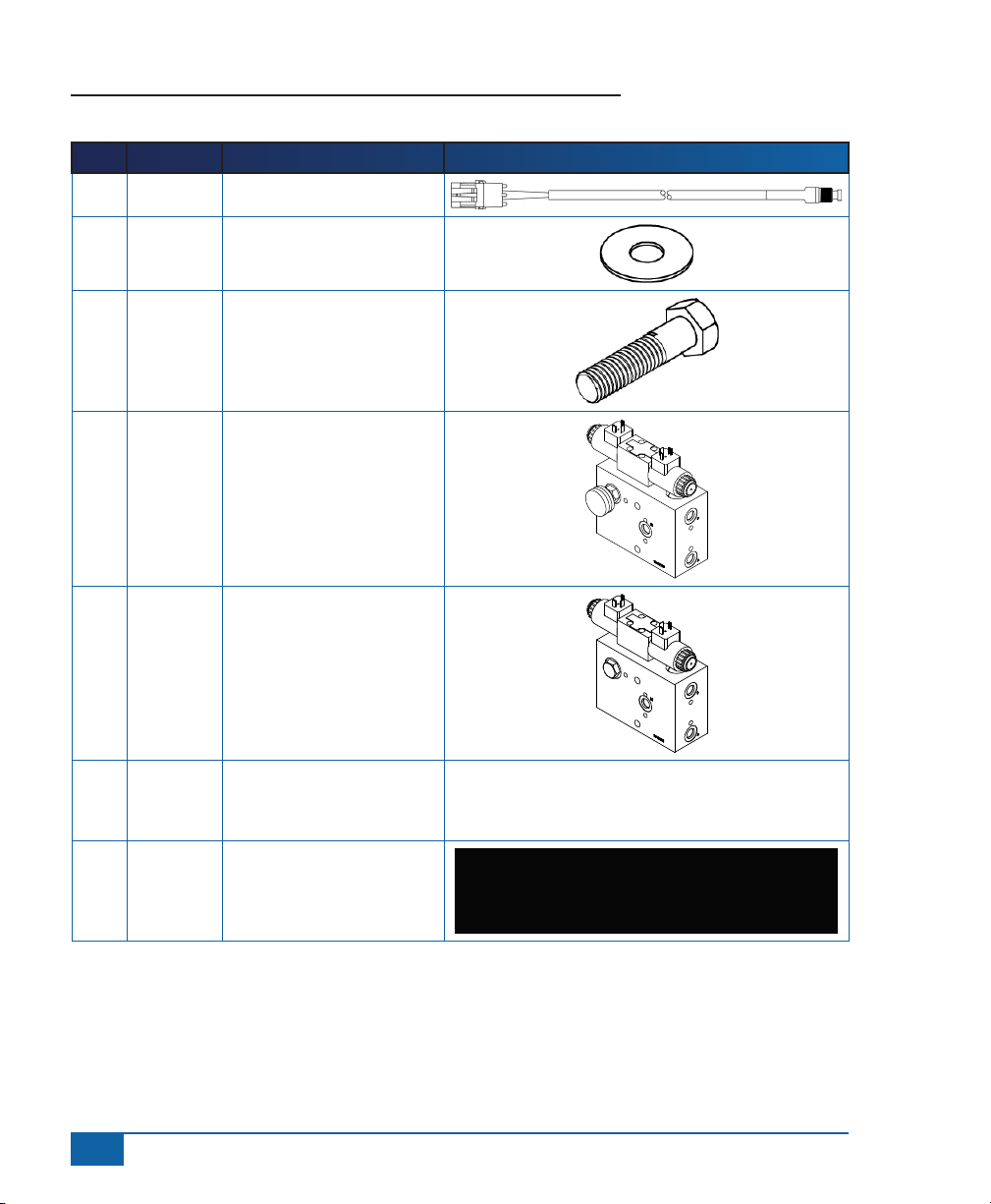
KIT CONTENTS
Unpack the installation kit and identify the required parts.
Item Part Number Description Quantity
A 32-04040 Switch, Engage/Disengage .....................................................................................1
B 350-0037 Washer, Flat, SST, 3/8 ............................................................................................2
C 60-04095 Bolt, Hex, SST, 3/8_16 x 1.5 ...................................................................................2
D* 35-02151 Valve, FieldPilot, CC LS ...........................................................................................1
D* 35-02180 Valve, FieldPilot, CC LS, PWM ................................................................................ 1
E 45-07703 Cable, SCM to Valve Interface Cable .....................................................................1
F 45-10103 Cable, Hydraulic Valve Interface .............................................................................1
G 60-04087 Bolt, Hex, SST, 3/8_16x3.25 ................................................................................... 2
H 60-07027 Nut, Hex, Nylock, SST, 3/8_16 ...............................................................................4
I 65-05176 Valve Bracket ..........................................................................................................1
J 68-01104 Hose, Hydraulic, 3/8x153″, 8 FORF-6FORF 90° ....................................................2
K 68-01105 Hose, Hydraulic, 3/8x20″, 6FORF-6FORF 90° .......................................................2
L 68-01106 Hose, Hydraulic, 1/4 x 18″, 6FORF-6FORF 90° .....................................................1
M 68-02012 Shuttle Tee Valve ....................................................................................................1
N 68-02071 6 ORFF Run Tee (F-M-M) ....................................................................................... 1
O 68-02072 6 MORFF - 90 - 6 FORFF .......................................................................................1
P 68-02073 6 MORB - 6 MORFF ...............................................................................................7
Q 68-02026 8 ORFF Run Tee (F-M-M) .......................................................................................2
R 68-02110 6 MORB - 6 FORFF ................................................................................................1
S 68-02118 M14 MORB - 6 MORFF .........................................................................................3
T 68-02119 John Deere Spacer ................................................................................................1
U 68-02120 John Deere Shuttle Disc .........................................................................................1
V 90-50013 Kit, Zip Ties (no pictured) ........................................................................................1
W 91-07011 Steering Wheel Switch Kit ......................................................................................1
®
* The valve included depends upon which vehicle kit was ordered.
www.teejet.com
3
Page 5
FieldPilot
Item Part # Description Illustration
A 32-04040 Switch, Engage/Disengage
B 350-0037 Washer, Flat, SST, 3/8
C 60-04095 Bolt, Hex, SST, 3/8_16 x 1.5
D* 35-02151 Valve, FieldPilot, CC LS
D* 35-02180 Valve, FieldPilot, CC LS,
®
PWM
E 45-07703 Cable, SCM to Valve
Interface Cable
F 45-10103 Cable, Hydraulic Valve
Interface
4
www.teejet.com
Page 6
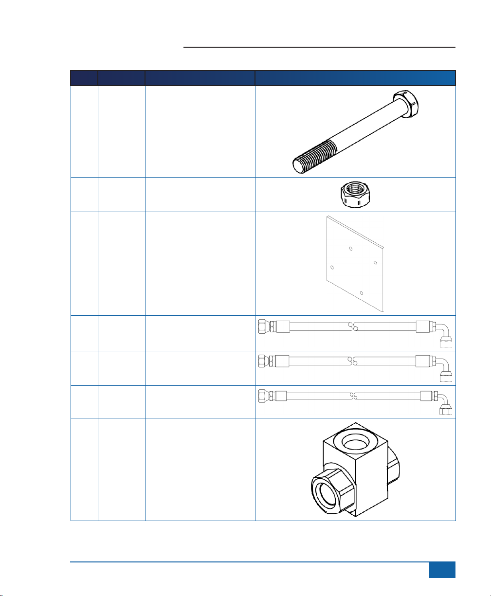
Item Part # Description Illustration
G 60-04087 Bolt, Hex, SST, 3/8_16x3.25
H 60-07027 Nut, Hex, Nylock, SST,
3/8_16
I 65-05176 Valve Bracket
FieldPilot
®
J 68-01104 Hose, Hydraulic, 3/8x153″, 8
FORF-6FORF 90°
K 68-01105 Hose, Hydraulic, 3/8x20″,
6FORF-6FORF 90°
L 68-01106 Hose, Hydraulic, 1/4 x 18″,
6FORF-6FORF 90°
M 68-02012 Shuttle Tee Valve
www.teejet.com
5
Page 7
FieldPilot
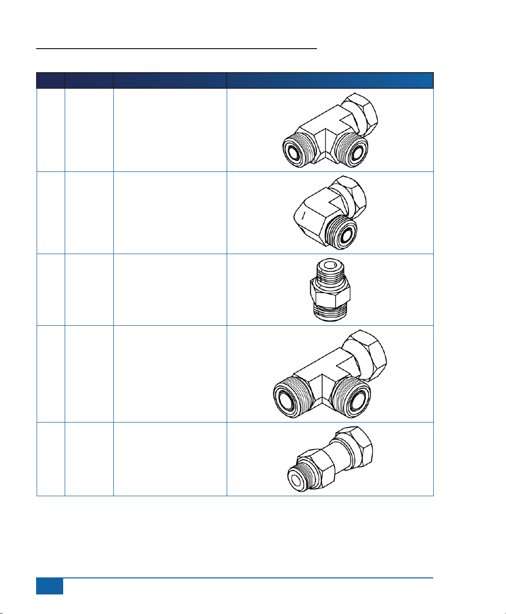
Item Part # Description Illustration
N 68-02071 6 ORFF Run Tee (F-M-M)
O 68-02072 6 MORFF - 90 - 6 FORFF
P 68-02073 6 MORB - 6 MORFF
®
Q 68-02026 8 ORFF Run Tee (F-M-M)
R 68-02110 6 MORB - 6 FORFF
6
www.teejet.com
Page 8

Item Part # Description Illustration
S 68-02118 M14 MORB - 6 MORFF
T 68-02119 John Deere Spacer
U 68-02120 John Deere Shuttle Disc
V 90-50013 Kit, Zip Ties (no pictured)
W 91-07011 Steering Wheel Switch Kit
* The valve included depends upon which vehicle kit was ordered.
FieldPilot
®
www.teejet.com
7
Page 9

FieldPilot
LS
P T B
A
LS
T
PB
P
P
Q Q R
R
L
P T B
A
LS
P
P
Q R Q
Q
®
Figure 1-1: Figure 1-2: Hydraulic Diagram
Replace plug with shuttle disc,
John Deere R196840 and
spacer John Deere RE58763
John Deere 8400 not using
power beyond option,
steering system installation,
Rev 0
FieldPilot
valve
Hydraulic
distribution block
on the rear of the
tractor
Steering
Unit
P T
8
www.teejet.com
Power Beyond
Pressure and
Load sense
John Deere 8400 using
beyond option, steering
system installation, Rev 0
Steering
Unit
FieldPilot
valve
LS
T
P T
Hydraulic
distribution block
on the rear of
the tractor
Page 10

FieldPilot
INSTALLATION
If there are questions concerning the installation of the FieldPilot system on this vehicle, or due to
the changes in component specications the parts supplied in the kit are not exactly as presented
in this document, please contact your dealer or TeeJet Customer service representative for
clarication before installation. TeeJet Technologies is not responsible for misuse or incorrect installation of
the system.
NOTE: BE VERY CAREFUL TO ABSOLUTELY SECURE ALL CABLES AND HOSES SO THAT THEY
DON’T INTERFERE WITH THE MANY MOVING PARTS OF THE MACHINE!
1. PREPARE THE FIELDPILOT VALVE BLOCK
Make sure the FieldPilot valve block is clean and free of dust. Work on a clean bench. Remove the plastic
plugs and install straight adapter (P) in the P, T, A, B, and LS ports. Take care not to damage the o-rings on
the adapters during this process.
Figure 1-2: Preparing FieldPilot Valve Block
®
P
P
www.teejet.com
9
Page 11

FieldPilot
®
2. MOUNT THE VALVE BRACKET ON THE VEHICLE
Find the two holes in the rear casting gusset plate on the right side of the tractor. Using the two bolts (G)
with nuts (H) and washers (B), attach the bracket (I) so that the mounting holes for the valve are up and to
the rear.
Figure 1-3: Mount the Valve Bracket
3. INSTALL FIELDPILOT VALVE ON MOUNTING BRACKET
Using the bolts and nuts (G) and (C) attach the FieldPilot valve to the bracket (I) so that Electronic actuator
is positioned to the rear and the manual adjust knob is positioned toward the center of the tractor.
Figure 1-4: Install Mounting Bracket on FieldPilot Valve
10
www.teejet.com
Page 12

FieldPilot
4. TRACTORS USING “POWER BEYOND” OPTION
NOTE: If vehicle is NOT using the John Deere “Power Beyond” option, skip to Step 6.
“Power Beyond” is accessed on the top of the rear valve block on the tractor. The load sense port will have
a run tee installed with one drop going to the power beyond load sense and the other going to the tank port
on top of the block. Where the tank line from the power beyond load sense enters the block, there is also an
orice plate. The pressure port is on the top of the valve block between the tank and the load sense ports. It
may have an additional line or it may be plugged, depending on whether or not the power beyond feature is
active on the tractor.
Figure 1-5: Power Beyond Option
Load sense Port
Pressure Port
Tank Port
®
www.teejet.com
11
Page 13

FieldPilot
®
5. MODIFYING THE POWER BEYOND INSTALLATION
It is necessary to install a shuttle tee valve (M) in the power beyond load sense port to allow either the
installed power beyond function or the FieldPilot valve (D) to trigger the load sense to the pump. Prepare the
shuttle tee valve by installing adapter (R) into the common port on the shuttle tee valve (M). Install two of
the adapters (P) into the other two ports of the shuttle tee value (M).
Figure 1-6: Shuttle Tee Valve
P P
M
R
Remove the run tee with the power beyond load sense and the tank return hose, from the adapter in the load
sense port on the tractor valve block. Connect adapter (R) previously installed on the common port of the
shuttle tee (M) on this adapter, in its place. Install the run tee that was removed to one port of the shuttle tee
valve (M) as shown. Remove the other end of the tank return hose from the elbow adapter in the tank return
port on the tractor valve block. Install a run tee (N) on the elbow adapter and install the power beyond tank
return hose to the end of the run tee.
NOTE: The “Power Beyond” tank return line has an orifice plate in it. Be sure this is still in place.
Remove the plug from the pressure port on top of the valve block and install adapter (S) in this opening.
Figure 1-7: Modifying Power Beyond Installation
Tank Return Hose
Adapter (S)
12
www.teejet.com
N
Tank Return Hose
Page 14

FieldPilot
6. TRACTORS NOT USING THE “POWER BEYOND” OPTION
If the tractor is not using the John Deere “Power Beyond” option, remove the plug from the load sense port
on the top of the rear tractor hydraulic valve block and install the John Deere shuttle disc R196840 (U) and
spacer RE58763 (T) into the port opening (threaded end up). Install one of the adapters (S) in the port.
Install the 90° adapter (O) on adapter (S) with the opening facing the right side of the tractor.
Remove the plug from the Tank port on top of the rear valve block and install an adapter (S) in this opening.
Remove the plug from the pressure port on top of the valve block and install an adapter (S) in this opening
as well.
Figure 1-8: Modifying without Power Beyond Installation
P Port
T
®
T Port
S
LS Port
S
O
U
www.teejet.com
13
Page 15

FieldPilot
®
7. PREPARING THE LEFT AND RIGHT STEERING CONNECTIONS
Underneath the tractor, just behind the front differential, nd the left and right steering cylinder hoses and
their connection point to the steel lines from under the cab.
Figure 1-9: Preparing the Left and Right Steering Connections
Uncouple the hoses from the steel lines (be sure to keep track of which hose is connected to which steel
line), and install Run Tees (Q) into the end of the steel lines. Then reattach the steering cylinder hoses to the
other ends of these run tees.
Figure 1-10: Uncouple the Hoses
14
www.teejet.com
Q
Page 16

FieldPilot
®
8. FIELDPILOT VALVE HOSE CONNECTIONS
The Pressure port of the FieldPilot Valve (D) will be connected to the pressure port on top of the rear tractor
hydraulic block using one hose (K). The T port from the FieldPilot Valve (D) will be connected to the open
tting on the tank return port on the top of the rear tractor hydraulic block using the second hose (K). The LS
port on the FieldPilot Valve (D) will be connected to the open tting at the load sense port on the top of the
rear tractor hydraulic block using hose (L). Refer to the hydraulic diagrams to understand how the FieldPilot
Valve (D) should t in the system.
Figure 1-11: Install FieldPilot Valve Hoses
K
L
9. INSTALL STEERING OUTPUT HOSES
Kit hoses (J) are rst connected to the A and B steering ports on the FieldPilot Valve (D).
Figure 1-12: Install Steering Output Hoses
J
www.teejet.com
15
Page 17

FieldPilot
Hoses (J) are routed forward under the cab to come out along the left side of the engine. It is best to remove
the engine cover on the left side of the tractor to allow easy access to this area.
Figure 1-13: Install Steering Output Hoses
®
Steering Hoses (J)
Finally, connect the end of the steering hoses (J) to the center drops of the run tees previously installed on
the steering cylinder hoses.
Figure 1-14: Install Steering Output Hoses (Continued)
This completes the hydraulic kit installation. Be sure all ttings are tight and all hoses are supported and
there are no chafe points in the hose runs.
16
www.teejet.com
Page 18

FieldPilot
®
10. INSTALL THE VALVE CONTROL CABLE
The valve control cable (F) will connect to the solenoids on the FieldPilot valve and will route into the rear of
the cab.
Figure 1-15: Control Cable Location
11. INSTALL STEERING DISENGAGE SENSOR (KIT 91-07011)
On the right hand side of the steering column in the cab, remove the lower bolt as indicated. Drill a hole in
the aluminum bracket from Kit 91-07011 for the bolt to t through. Install the aluminum bracket and bend it
as illustrated. Attach the magnets (included) to the steering shaft. The magnets may need to be cut in two.
If the magnets are labeled North and South, alternate between them. The more magnets installed, the more
sensitive the disengage feature. Install the sensor and adjust to 1/8″ clearance. Connect the sensor to the
cable labeled Steering Wheel Sense. Tie up the cable so it does not interfere with any moving parts.
Figure 1-16: Figure 1-16: Installing Steering Disengage Switch
Bolt to be removed
www.teejet.com
17
Page 19

FieldPilot
®
12. INSTALL THE ENGAGE/DISENGAGE SWITCH
Connect item (D) to the connector on the SCM harness labeled Remote Engage/Disengage. Install the push
button in a location that is easily accessible during operation of the machine. This switch (D) is not required
if the optional foot switch 32-04020 is used.
Figure 1-17: Engage/Disengage Switch
18
www.teejet.com
Page 20

FieldPilot
13. RECOMMENDED ELECTRONICS INSTALLATION
The Steering Control Module (SCM) should be mounted securely to the oor of the cab. The control console
can be mounted to the operator’s preference. The GPS antenna should be mounted as far forward as
possible on top of the cab on a metal surface of at least 4″ square.
Figure 1-18: Recommended Electronics Installation
®
www.teejet.com
19
Page 21

FieldPilot
®
14. VERIFY OPERATION OF HYDRAULICS
AND SET THE STEERING CONTROL RATE
Clean and pick up the area around the vehicle and make certain that it is safe to operate. Start the engine
and check hydraulic connections for leaks. Rotate the steering wheel from one extreme to the other and back
to center, check for leaks. While steering through the extremes of movement, check the cables and hoses for
wear points and strain, adjust as necessary.
If using a Matrix series console and PWM control, then the oil ow rate adjustment
is accomplished through the console. The target lock to lock time is 5 seconds.
Refer to the Matrix manual for further instructions.
If using a CL220 or CL230 console then refer to the following instructions for adjusting the oil ow rate.
Adjust the hydraulic oil ow control knob on the FieldPilot valve to a starting posi¬tion of 2½ turns
from completely closed. Adjust the oil ow by turning the knob clockwise to reduce ow (increase seconds)
and counter-clockwise to increase ow (decrease seconds).
Use the electronic steering control console to perform the left to right steering test, counting the seconds
to move the wheels from full left to full right and also in the opposite direction. It is a good idea to have the
vehicle moving forward very slowly during these tests so there is not excessive side pressure on the tires.
If you nd that the machine steers in the opposite direction from that being commanded in this steering test
sequence, switch the valve connectors at the FieldPilot valve coils.
Do this a number of times, adjusting the oil ow between tests, until a lock to lock steering response of
ap¬proximately 16 seconds is observed using a CenterLine® 220. Adjust to 12 seconds when using a
CenterLine® 230BP. Use the locking nut to secure this ow setting. The coils on the FieldPilot valve also
have manual push button overrides.
NOTE: To activate the manual overrides, a tool such as a small screwdriver or allen wrench must be inserted
into the end of the coil to depress the override button.
WARNING: PINCH POINT HAZARD! To prevent serious injury or death, avoid unsafe practice
while manually operating hydraulic steering circuits. Keep others away and stay clear of
mechanical steering linkages.
15. COMPLETE ELECTRONIC INSTALLATION
Refer to the owner’s manual supplied with the automated steering system to complete the electronic
installation and setup.
20
www.teejet.com
Page 22

F I E L D P I L O T®
U S E R M A N U A L
A series of equipment-specic hydraulic installation kits have been developed to
work in conjunction with your assisted steering system. This kit contains the necessary components and instructions to install assisted steering hydraulics on the John
Deere 8x00 and 8x10 Series wheel tractors. Please review this manual thoroughly
before beginning the installation process.
1801 Business Park Drive
Springeld, Illinois 62703 USA
Tel: (217) 753-8424 • Fax: (217) 753-8426
www.teejet.com
98-05117 R1
© TeeJet Technologies 2010
 Loading...