

Page 1

F I E L D P I L O T®
U S E R M A N U A L
Assisted Steering Hydraulic Installation Manual for
Vehicle Kit Number 91-02332
Fits Only Versatile 305,340,375,435,485,535 & 575
Page 2

Page 3

FieldPilot
®
FIELDPILOT®
Copyrights
© 2010 TeeJet Technologies. All rights reserved. No part of this document or the computer programs
described in it may be reproduced, copied, photocopied, translated, or reduced in any form or by any
means, electronic or machine readable, recording or otherwise, without prior written consent from TeeJet
Technologies.
Trademarks
Unless otherwise noted, all other brand or product names are trademarks or registered trademarks of their
respective companies or organizations.
Limitation of Liability
TEEJET TECHNOLOGIES PROVIDES THIS MATERIAL “AS IS” WITHOUT WARRANTY OF ANY KIND,
EITHER EXPRESSED OR IMPLIED. NO COPYRIGHT LIABILITY OR PATENT IS ASSUMED. IN NO EVENT
SHALL TEEJET TECHNOLOGIES BE LIABLE FOR ANY LOSS OF BUSINESS, LOSS OF PROFIT, LOSS
OF USE OR DATA, INTERRUPTION OF BUSINESS, OR FOR INDIRECT, SPECIAL, INCIDENTAL, OR
CONSEQUENTIAL DAMAGES OF ANY KIND, EVEN IF TEEJET TECHNOLOGIES HAS BEEN ADVISED
OF SUCH DAMAGES ARISING FROM TEEJET TECHNOLOGIES SOFTWARE.
www.teejet.com
1
Page 4
FieldPilot
®
PREPARATION
1. Before beginning the installation, thoroughly clean the vehicle to remove dirt and contaminants that might
get into the hydraulic circuit.
2. Park the vehicle on a clean, level oor with adequate clearance to work around.
3. Do not attempt to loosen any hydraulic ttings while the engine is running.
4. Allow the motor and the hydraulics to cool until it is no more than warm to the touch before proceeding.
5. Prior to loosening any hydraulic ttings, be sure to have the appropriate plugs and caps available in order
to limit loss of hydraulic uid from the open ttings.
PREVENT HYDRAULIC SYSTEM CONTAMINATION. It is essential to thoroughly clean hydraulic
system ttings and hose connections prior to disconnecting or removing them. Use a spray
cleaner such as “Brake Clean” to prevent hydraulic system contamination. Note that o-rings used
on ORB and ORFF type ttings may be damaged by solvent cleaners such as “Brake Clean”. If a tting is to
be cleaned internally, the o-ring should rst be removed and cleaned with a berless cloth.
IMPORTANT
WARNING: HOT, HIGH PRESSURE FLUID HAZARD. Hydraulic oil may be hot and under
extreme pressure. To prevent serious injury or death, relieve system pressure and allow the
system to cool before repairing or disconnecting. Wear proper hand and eye protection when
searching for leaks, using wood or cardboard instead of hands. Keep all hydraulic components in good
repair.
WARNING: PINCH POINT HAZARD! To prevent serious injury or death, avoid unsafe practice
while manually operating hydraulic steering circuits. Keep others away and stay clear of
mechanical steering linkages.
TO AVOID EXCESS LEAKAGE, DO NOT TURN THE STEERING WHEEL WHILE
THE FITTINGS ON THE MANUAL STEERING VALVE ARE DISCONNECTED.
2
www.teejet.com
Page 5

FieldPilot
KIT CONTENTS
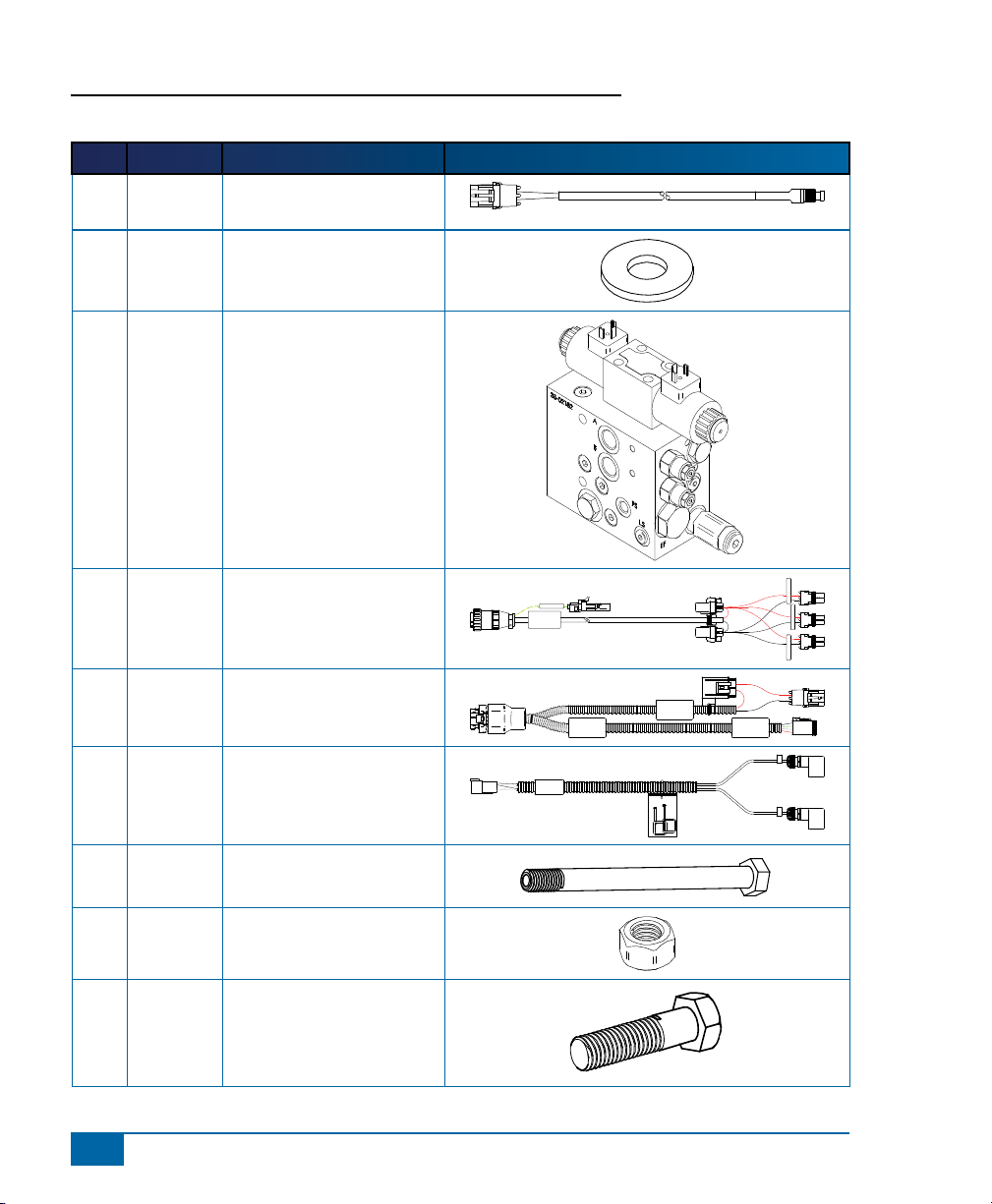
Unpack the installation kit and identify the required parts.
Item Part Number Description Quantity
A 32-04040 Switch, Engage/Disengage ......................................................................................1
B 350-0037 Washer, Flat - 3/8” SST ...........................................................................................3
C 35-02187 Valve, FieldPilot, PWM, 7.9GPM, CC ......................................................................1
D 45-05396 Cable, PWR 3 POS AMP To 3-2 POS WP ..............................................................1
E 45-07703 Harness, SCM .........................................................................................................1
F 45-10103 Harness, Valve .........................................................................................................1
G 60-04089 Bolt, Hex- 3/8-16 x 3-3/4” SST .................................................................................2
H 60-07027 Nut, NyLock 3/8-16, SST .........................................................................................3
I 60-04095 Bolt, Hex- 3/8-16 x 1-1/2” SST .................................................................................1
J 65-05162 Bracket, Hyd. Block Mount ......................................................................................1
K 68-01091 Hose, Hyd - 3/8” x 36”, #6FJIC x #6FJIC .................................................................1
L 68-01113 Hose, Hyd - 3/8” x 24”, #6FORF x #6FORF 90º ......................................................1
M 68-01233 Hose, Hyd - 1/2” x 52”, #12FORF x #8FJIC 90º ......................................................2
N 68-01234 Hose, Hyd - 1/2” x 17”, #12FORF x #12FJIC 90º ....................................................1
O 68-01235 Hose, Hyd - 1/2” x 50”, #12FORF x #8FJIC ............................................................1
P 68-02012 Shuttle Tee ...............................................................................................................1
Q 68-02017 Adapter, Hyd. - #12MJIC x #12MORB .....................................................................1
R 68-02019 Adapter, Hyd. - #6MJIC x #6MORB .........................................................................2
S 68-02033 Adapter, Hyd. Run Tee - #12 ORF ..........................................................................4
T 68-02073 Adapter, Hyd. - #6MORF x #6MORB .......................................................................1
U 68-02094 Adapter, Hyd. - #8MJIC x #8MORB .........................................................................3
V 68-02173 Adapter, Hyd. 90º EL - #6MJIC x #4MORB .............................................................1
W 90-50013 Cable Tie Kit, 15 ......................................................................................................1
X 90-02472 Kit, Patch Antenna EXT 10’ ......................................................................................1
Y 91-07011 Steering Wheel Switch Kit .......................................................................................1
Z 91-00022 Kit, Articulated Gyro Module ....................................................................................1
AA 98-05211 Installation Manual Versatile 305,340,375,435,485,535,575 ...................................1
®
www.teejet.com
3
Page 6
FieldPilot
Switched +12v
45-05396
DC: xx/xx
Power Cable
Power Cable
Power Cable
SCM Power I/O
45-07703
DC: xx/xx
Valve Output
Power
A
B
45-10103
DC:xx/xx
®
Item Part # Description Illustration
A 32-04040 Switch, Engage/Disengage,
Momentary
B 350-0037 Washer, Flat - 3/8” SST
C 35-02187 Valve, FieldPilot, PWM,
7.9GPM, CC
D 45-05396 Cable, PWR 3 POS AMP To
3-2 POS WP
E 45-07703 Harness, SCM
F 45-10103 Harness, Valve
G 60-04089 Bolt, Hex- 3/8-16 x 3-3/4”
SST
H 60-07027 Nut, NyLock 3/8-16, SST
I 60-04095 Bolt, Hex- 3/8-16 x 1-1/2"
SST
4
www.teejet.com
Page 7
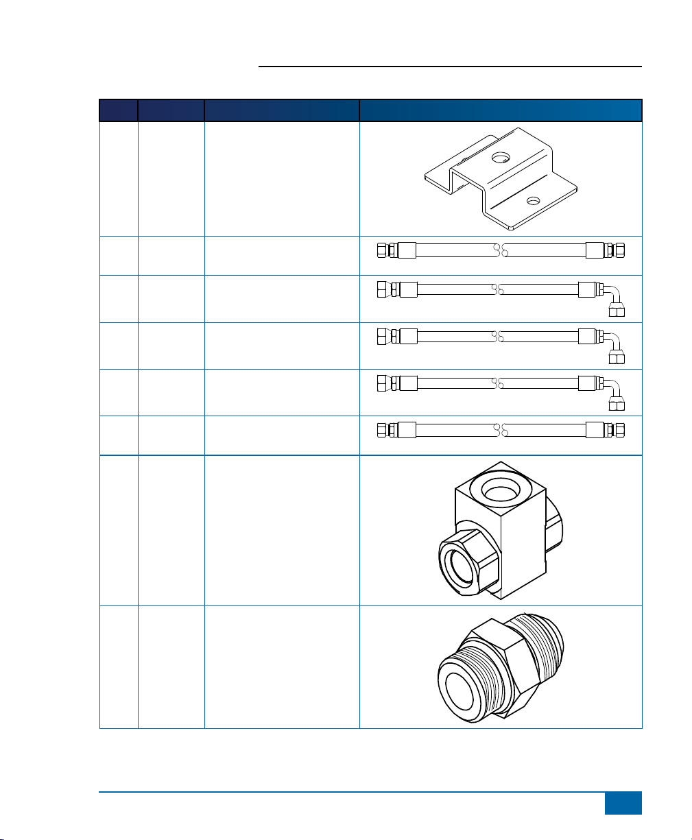
Item Part # Description Illustration
J 65-05162 Bracket, Hyd. Block Mnt
K 68-01091 Hose, Hyd - 3/8" x 36",
#6FJIC x #6FJIC
L 68-01113 Hose, Hyd - 3/8" x 24",
#6FORF x #6FORF 90º
M 68-01233 Hose, Hyd - 1/2" x 52",
#12FORF x #8FJIC 90º
N 68-01234 Hose, Hyd - 1/2" x 17",
#12FORF x #12FJIC 90º
O 68-01235 Hose, Hyd - 1/2" x 50",
#12FORF x #8FJIC
P 68-02012 Hyd Load Shuttle Tee-
#6FORB
FieldPilot
®
Q 68-02017 Adapter, Hyd. - #12MJIC x
#12MORB
www.teejet.com
5
Page 8
FieldPilot
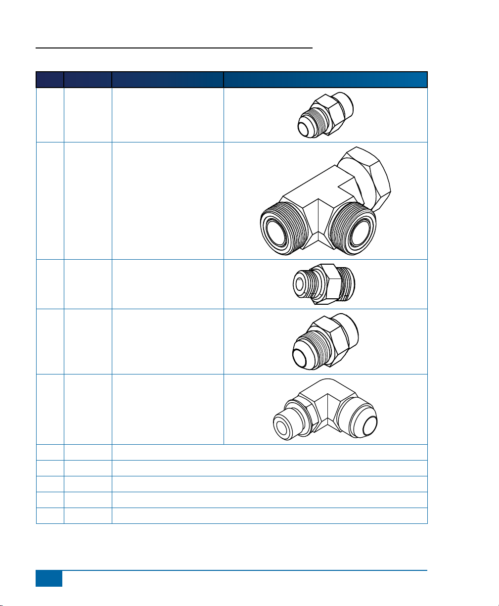
Item Part # Description Illustration
R 68-02019 Adapter, Hyd. - #6MJIC x
S 68-02033 Adapter, Hyd. Run Tee - #12
T 68-02073 Adapter, Hyd. - #6MORF x
U 68-02094 Adapter, Hyd. - #8MJIC x
®
#6MORB
ORF
#6MORB
#8MORB
V 68-02173 Adapter, Hyd. 90º - #6MJIC
x #4MORB
W 90-02472 Kit, Patch Antenna EXT 10’
X 90-50013 Cable Tie Kit, 15
Y 91-07011 Steering Wheel Switch Kit
Z 91-00022 Kit, Articulated Gyro Module
AA 98-05211 Installation Manual Versatile 305, 340, 375, 435, 485, 535, 575
6
www.teejet.com
Page 9
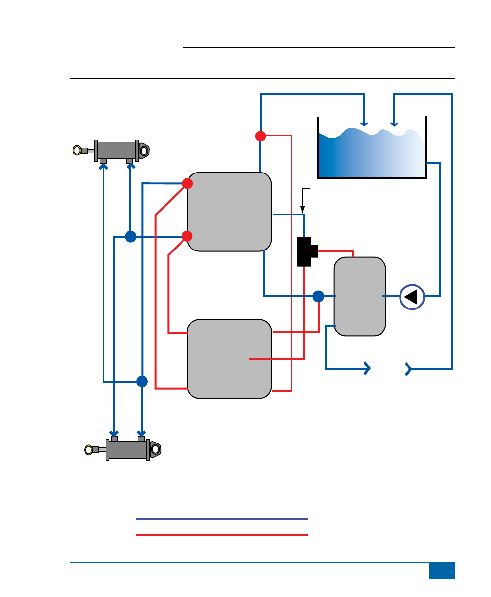
Figure 1-1: Hydraulic Diagram
Manual Steering
Valve
R
L
LS
FieldPilot
Tank
T
P
Hose disconnected from LS on
Priority Valve reattached to port of
Shuttle Tee Valve
P (Shuttle
Tee)
L
®
Existing Hoses
Hoses From Kit
LS
CF
M
B
LS
M
A
FieldPilot Valve
N
P
K
O
T
EF
Priority Valve
Auxiliary
Pump
P
all existing
plumbing
www.teejet.com
7
Page 10

FieldPilot
Matrix 840G
®
Figure 1-2: System Diagram
Matrix
FieldPilot
Optional Accessory
Power
Optional RXA-30 GPS Antenna
Kit, RAM Mount w/Suction Cup
90-02349 (Matrix 570G)
90-02700 (Matrix 840G)
16-00022: RealView Camera
45-07703
SCM Power I/O
SCM Power I/O
45-07703
DC: xx/xx
45-07708
SCM Harness
Valve Output
GPS In
COM 1
78-50187
65-05226
Kit, Bracket
RXA-30 Antenna
45-05615 4 Pos.
45-05765 8 Pos.
Speed/Sense Cable
78-08061
Steering Control
Module (SCM)
GPS Power
Seat Sensor
78-50155 GPS Patch Antenna
45-05786: 20’/6 m
45-05787: 30’/9 m
Antenna Cable
Matrix 570G
75-30055
75-30056 w/ClearPath
Camera
45-05617: 20'/6m
45-05618: 60'/18m
Camera Extension Cable
to RS-232
Steering
Wheel Sense
Speed Cable
5 Pos.
4 Pos.
8 Pos.
32-50008
Switch
+12V
RS-232
CAN
75-30070
75-30071 w/ClearPath
Power/DATA
45-05626
45-05626
Pwr/CAN/Data
Cable
(included with
FieldPilot and
BoomPilot kits)
CAN
POWER IN
8 Pos.
to TJ CAN
(Terminated)
3A Fuse
45-08117 CAN Extension Cable 20'/6m
Engage/Disengage
SCM COM 2
Remote
45-08101 CAN Terminator
8
www.teejet.com
45-10103
Harness
Steering
(A+B)
45-10103
DC: xx/xx
32-04040
Remote
Engage/
Disengage
Switch
Steering
Valve
32-04020
DC: xx/xx
Engage / Disengage
78-08073
Articulated Gyro Module (AGM)
32-04020
Optional
Footswitch
45-07716
Harness TGM
Tilt Gyro Module
CAN Harness
45-07716
DC: xx/xx
CAN Tee
45-05381
Battery 12'/3.5m
w/15 Amp Fuses
DC: xx/xx
45-05381
C
o
n
n
e
(
ct
+
1
o
2
t
v)
o
Page 11
FieldPilot
INSTALLATION
If there are questions concerning the installation of the FieldPilot system on this vehicle, or due to
the changes in component specications the parts supplied in the kit are not exactly as presented
in this document, please contact your dealer or TeeJet Customer service representative for
clarication before installation. TeeJet Technologies is not responsible for misuse or incorrect installation of
the system.
NOTE: BE VERY CAREFUL TO ABSOLUTELY SECURE ALL CABLES AND HOSES SO THAT THEY
DON’T INTERFERE WITH THE MANY MOVING PARTS OF THE MACHINE!
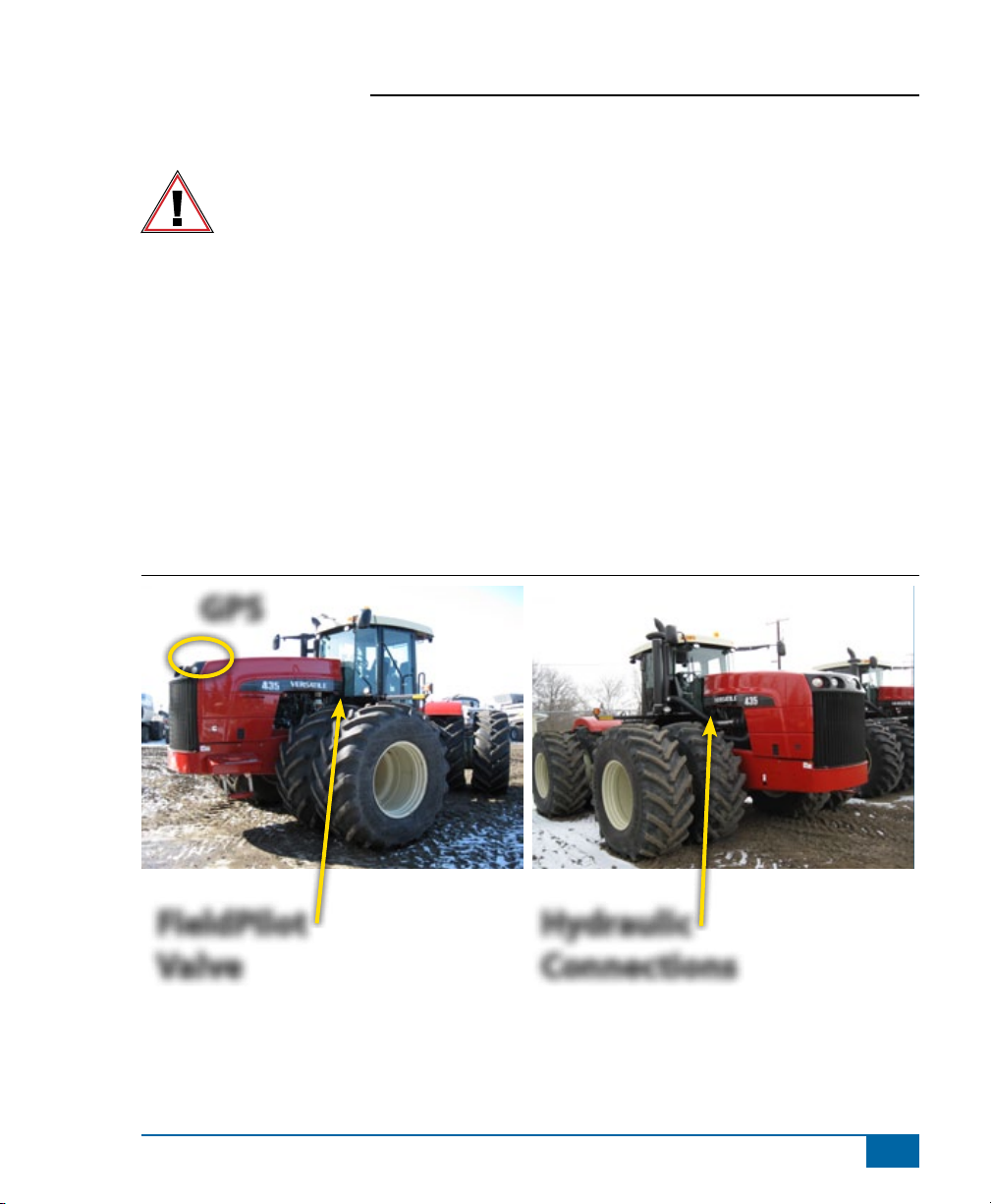
Overview of the Machine
• The FieldPilot valve will mount on the hood frame directly in front of the cab.
• Hydraulic connections will be made at the orbital and priority valve located just in front of the cab.
• The GPS antenna will mount on the hood.
• The cables will enter the bottom-right-rear of the cab
NOTE: All references to left and right are stated as if the user is seated in the driver’s seat.
Figure 1-3: Overview of the Machine
GPS
®
FieldPilot
Valve
Hydraulic
Connections
www.teejet.com
9
Page 12

FieldPilot
1. PREPARE THE FIELDPILOT VALVE
Install adapter (U) in the A, B, and T ports of the FieldPilot valve (C). Install adapter (V) in the LS port and
install adapter (Q) in the P port
Figure 1-4: Prepare the FieldPilot Valve
®
U
U
U
U
Q
V
V
U
U
Q
10
www.teejet.com
Page 13

FieldPilot
®
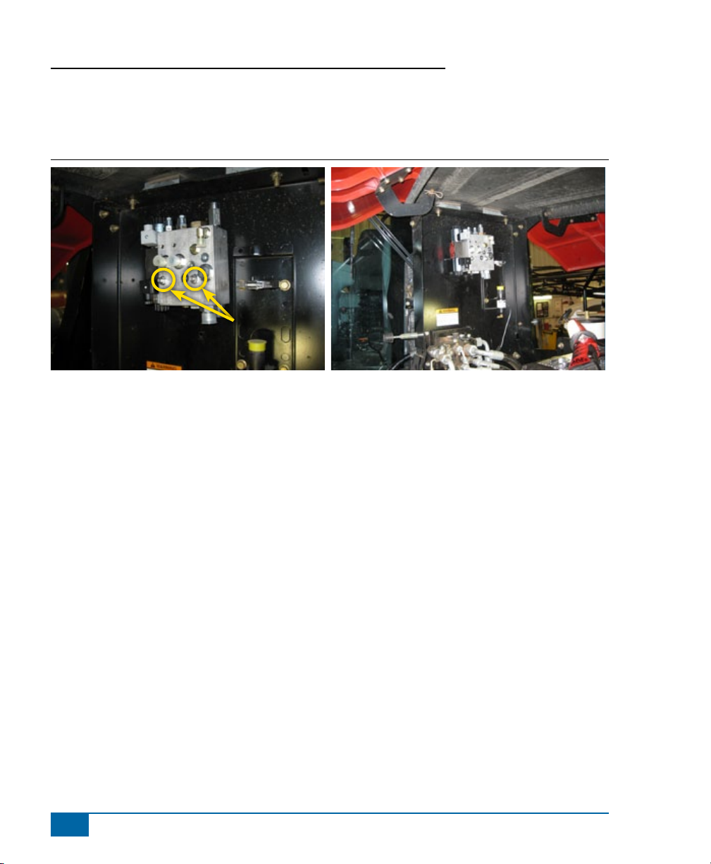
2. INSTALL THE FIELDPILOT VALVE BRACKET
Using the existing hole in the hood frame plate and parts (B, H, & I) to mount the bracket (J).The horn will
need to be relocated to another existing hole.
NOTE: It will be easier to the mount the FieldPilot valve if the bolts (G) are inserted in the bracket (J) before
it is installed.
Figure 1-5: Install Mounting Bracket for FieldPilot Valve
Move to here
J
www.teejet.com
11
Page 14
FieldPilot
®
3. MOUNT THE FIELDPILOT VALVE
Using parts (B, G, & H), mount the FieldPilot valve to the bracket. The P & T ports will face down.
Figure 1-6: Mount the FieldPilot Valve
B, G, H
12
www.teejet.com
Page 15

FieldPilot
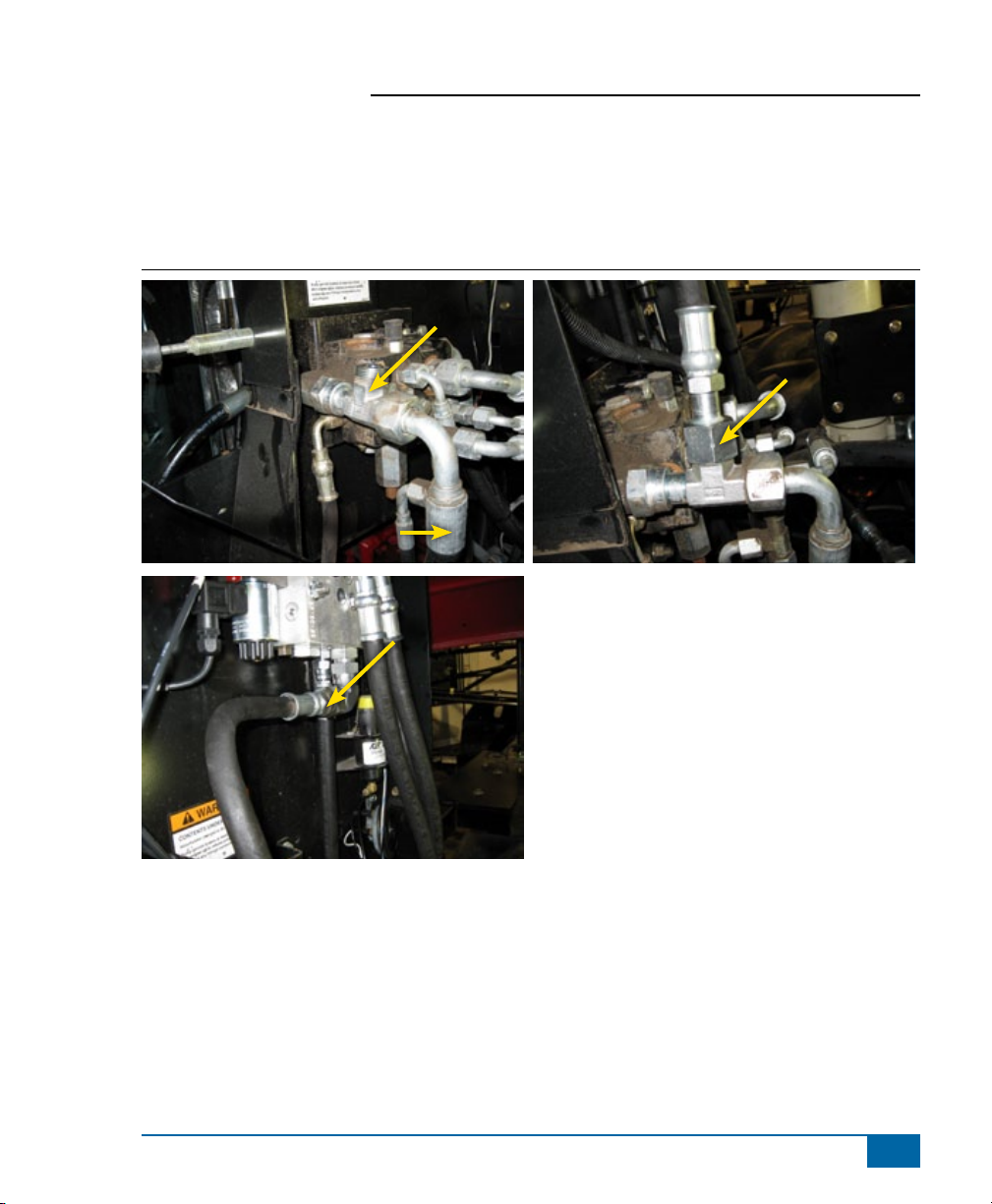
4. INSTALL THE SHUTTLE TEE
Install adapters (R & T) in the Shuttle tee (P) as shown. Disconnect the existing LS hose from the Priority
Valve and connect it to the prepared shuttle tee. Connect hose (L) from the shuttle tee to the open port
where the original LS hose connected. Then install hose (K) from the shuttle tee to the LS port of the
FieldPilot valve.
Figure 1-7: Install the Shuttle Tee and Adapters
®
T
Original LS
Hose
L
R
R
Disconnect
K
K
www.teejet.com
13
Page 16

FieldPilot
®
5. INSTALL THE TANK HOSE AND ADAPTERS
The tank hose will connect from a run tee at the orbital to the T port on the FieldPilot valve. Disconnect the
hose from the T port of the orbital and install run tee (S). Reconnect the original hose to the run of the tee.
Then connect hose (O) from the branch of run tee (S) to the T port of the FieldPilot valve.
Figure 1-8: Install The Tank Hose and Adapters
T Port
O
S
O
14
www.teejet.com
Page 17
FieldPilot
6. INSTALL PRESSURE HOSE AND ADAPTER
Disconnect the pressure hose from the Priority Valve as shown and install run tee (S). Reconnect the
original pressure hose to the run of the tee. Then connect hose (N) from the branch of run tee (S) to the P
port on the FieldPilot valve.
Figure 1-9: Install Pressure Hose and Adapter
S
N
Pressure Hose
®
N
www.teejet.com
15
Page 18
FieldPilot
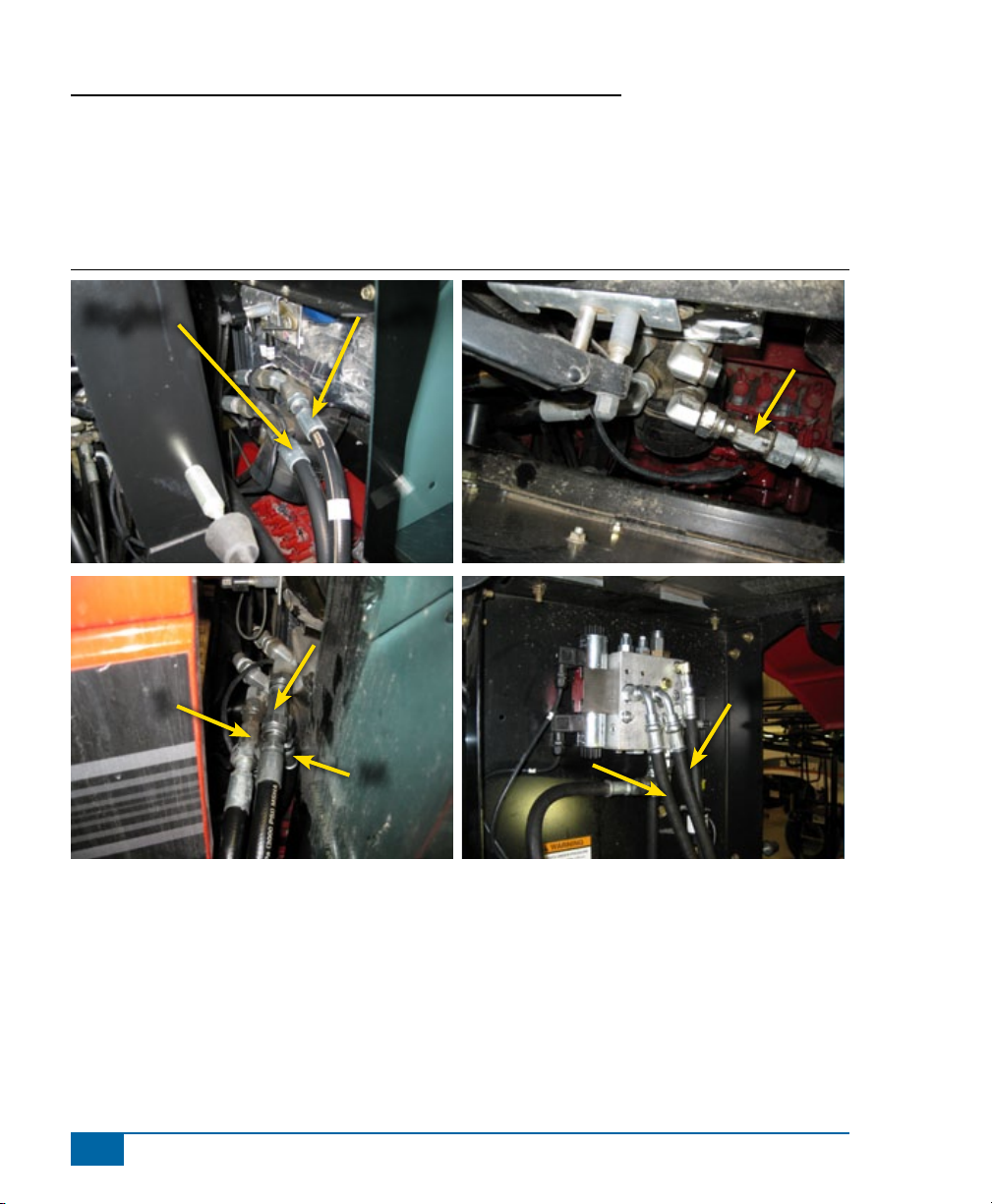
7. INSTALL STEER HOSES AND ADAPTERS
Disconnect the left and right steer hoses at the orbital and install run tees (S). (Be sure to label the steer
hoses before disconnecting them.) Reconnect the original steer hoses the run of the tees. Then connect
hoses (M) from the branch of the run tees to the A & B ports of the FieldPilot valve.
Figure 1-10: Install Steer Hoses and Adapters
®
Right Left
S
S
16
www.teejet.com
S
M
M
M
Page 19

FieldPilot
8. INSTALL THE VALVE CONTROL CABLE
The valve control cable (F) will connect to the FieldPilot valve and route to the back rear corner of the cab.
Figure 1-11: Install the Valve Control Cable
9. INSTALL STEERING DISENGAGE SWITCH KIT 9107011
The steering disengage kit (Z) is used to automatically disengage FieldPilot when the steering wheel is
turned. The magnets mount on the steering shaft or other rotating part of the steering wheel and the sensor
mounts so that there is a 1/8” clearance between the sensor and magnet.
®
Figure 1-12: Install Steering Disengage Switch (Kit 91-07011)
www.teejet.com
17
Page 20

FieldPilot
®
10. INSTALLATION OF ENGAGE/DISENGAGE SWITCH
Connect item (A) to the connector on the SCM harness labeled Remote Engage/Disengage. Install the push
button in a location that is easily accessible during operation of the machine. This switch (A) is not required
if the optional foot switch 32-04020 is used.
Figure 1-13: Engage/Disengage Switch
18
www.teejet.com
Page 21

FieldPilot
®
11. RECOMMENDED ELECTRONICS INSTALLATION
The Steering Control Module (SCM) should be mounted securely to the oor of the cab as far forward in the
cab as possible.
NOTE: There are wires under the floor mat so be sure that the SCM mounting does not damage them.
The control console can be mounted to the operator’s preference. The GPS antenna should be mounted
near the nose of the vehicle on a metal surface of at least 4” square.
The Articulated Gyro Module (AGM) should be mounted towards the rear of the vehicle on a at surface that
is horizontal to the ground. Plug the CAN extension cable to the AGM Harness (45-07716) as well as the
CAN terminator. Route the other end of the CAN extension cable towards the cab and connect to the CAN on
the SCM harness.
Figure 1-14: Recommended Electronics Installation
Console
GPS
SCM
AGM
www.teejet.com
19
Page 22

FieldPilot
®
12. VERIFY OPERATION OF HYDRAULICS AND SET THE STEERING
CONTROL RATE
Clean and pick up the area around the vehicle and make certain that it is safe to operate. Start the engine
and check hydraulic connections for leaks. Rotate the steering wheel from one extreme to the other and back
to center, check for leaks. While steering through the extremes of movement, check the cables and hoses for
wear points and strain, adjust as necessary.
The nal oil ow rate adjustment is accomplished through the Matrix console. The
target lock to lock time is 8-10 seconds and the valve frequency is 175. Refer to the
Matrix manual for further instructions.
NOTE: To activate the manual overrides, a tool such as a small screwdriver or allen wrench must be inserted
into the end of the coil to depress the override button.
WARNING: PINCH POINT HAZARD! To prevent serious injury or death, avoid unsafe practice
while manually operating hydraulic steering circuits. Keep others away and stay clear of
mechanical steering linkages.
13. COMPLETE ELECTRONIC INSTALLATION
Refer to the owner’s manual supplied with the automated steering system to complete the electronic
installation and setup.
20
www.teejet.com
Page 23

Page 24

F I E L D P I L O T®
U S E R M A N U A L
A series of equipment-specic hydraulic installation kits have been
developed to work in conjunction with your assisted steering system. This
kit contains the necessary components and instructions to install assisted
steering hydraulics on the Versatile 305,340,375,435,485,535,575. Please
review this manual thoroughly before beginning the installation process.
1801 Business Park Drive
Springeld, Illinois 62703 USA
Tel: (217) 747-0235 • Fax: (217) 753-8426
www.teejet.com
98-05211 R1
© TeeJet Technologies 2010
 Loading...