

Page 1

FIELDWARE® TOOLS
USER MANUAL
Utilities for Guidance Applications
Software Version 3.00a
Page 2

Table of Contents
MAP MANAGER 1
Base Maps .............................................................................................................................................................. 3
Color Prescription Maps ................................................................................................................................... 4
Object Information Query ............................................................................................................................... 5
The Map Manager Tool Bar.............................................................................................................................. 6
MENUES 8
The File Menu ....................................................................................................................................................... 8
The Layers Menu ................................................................................................................................................. 9
The View Menu .................................................................................................................................................. 10
The Edit Menu .................................................................................................................................................... 11
The Build Menu .................................................................................................................................................12
THE BUILD PROFILE APPLICATION 13
Customer Prole ...............................................................................................................................................13
Dealer .................................................................................................................................................................... 14
Product .................................................................................................................................................................15
Applicator ............................................................................................................................................................16
BUILDING AN APPLICATION REPORT 17
The Maps/File Dialog .......................................................................................................................................18
The Field Conditions Dialog ..........................................................................................................................19
The Product Setup Dialog .............................................................................................................................20
Running the Product Wizard ........................................................................................................................21
The Job Setup Dialog ...................................................................................................................................... 23
The Document Setup Dialog ........................................................................................................................ 23
CONVERTING FILES USING MAP MANAGER 25
The File Conversion Process .......................................................................................................................... 25
Step 1: Selecting The Source File ...................................................................................................25
Step 2: Selecting The Destination File .............................................................................................27
Step 3: Selecting The Type Of Objects To Convert .........................................................................27
Step 4: Selecting A Template ........................................................................................................... 28
Step 5: Converting The File .............................................................................................................29
FIELD TRANSFER TEMPLATES 30
Setting Up A Field Transfer Template ........................................................................................................32
Conguring A Field Transfer .........................................................................................................................33
Page 3

ABOUT FORM A SAMPLING PATTERN 35
QUICK START 36
THE SETUP PROCESS USING MENU PAGES 37
The Main Setup Page.......................................................................................................................................37
Client-Farm-Field Menu Fields ........................................................................................................37
Setup File Menu Field ......................................................................................................................37
Background File Menu Field ............................................................................................................37
Output File Menu Field ....................................................................................................................37
The Grid Setup Page ........................................................................................................................................38
Store Grid Menu Field ......................................................................................................................38
Store Points Menu Field ..................................................................................................................38
Sampling Pattern Menu Field ..........................................................................................................38
Cell Area Menu Field ........................................................................................................................................39
Cell Horizontal and Vertical Length Menu Fields .................................................................................. 39
Completing the Setup Process ....................................................................................................................40
Orienting the Sample Grid ............................................................................................................................ 40
Rotating the Grid ..............................................................................................................................................41
Rotating the grid by entering a rotation angle ..................................................................................41
Rotating the grid using the “Spin” buttons .......................................................................................42
Shifting the Grid ................................................................................................................................................ 42
Shifting the grid using the shift buttons ............................................................................................42
Shifting the grid using the mouse ....................................................................................................42
Completing the Grid Orientation................................................................................................................42
Positioning the Sample Points .....................................................................................................................43
Page 4
Fieldware
®
Tools
FIELDWARE TOOLS
Copyrights
© 2011 TeeJet Technologies. All rights reserved. No part of this document or the computer programs described
in it may be reproduced, copied, photocopied, translated, or reduced in any form or by any means, electronic or
machine readable, recording or otherwise, without prior written consent from TeeJet Technologies.
Trademarks
Unless otherwise noted, all other brand or product names are trademarks or registered trademarks of their
respective companies or organizations.
Limitation of Liability
TEEJET TECHNOLOGIES PROVIDES THIS MATERIAL “AS IS” WITHOUT WARRANTY OF ANY KIND, EITHER
EXPRESSED OR IMPLIED. NO COPYRIGHT LIABILITY OR PATENT IS ASSUMED. IN NO EVENT SHALL
TEEJET TECHNOLOGIES BE LIABLE FOR ANY LOSS OF BUSINESS, LOSS OF PROFIT, LOSS OF USE OR
DATA, INTERRUPTION OF BUSINESS, OR FOR INDIRECT, SPECIAL, INCIDENTAL, OR CONSEQUENTIAL
DAMAGES OF ANY KIND, EVEN IF TEEJET TECHNOLOGIES HAS BEEN ADVISED OF SUCH DAMAGES
ARISING FROM TEEJET TECHNOLOGIES SOFTWARE.
About Fieldware Tools
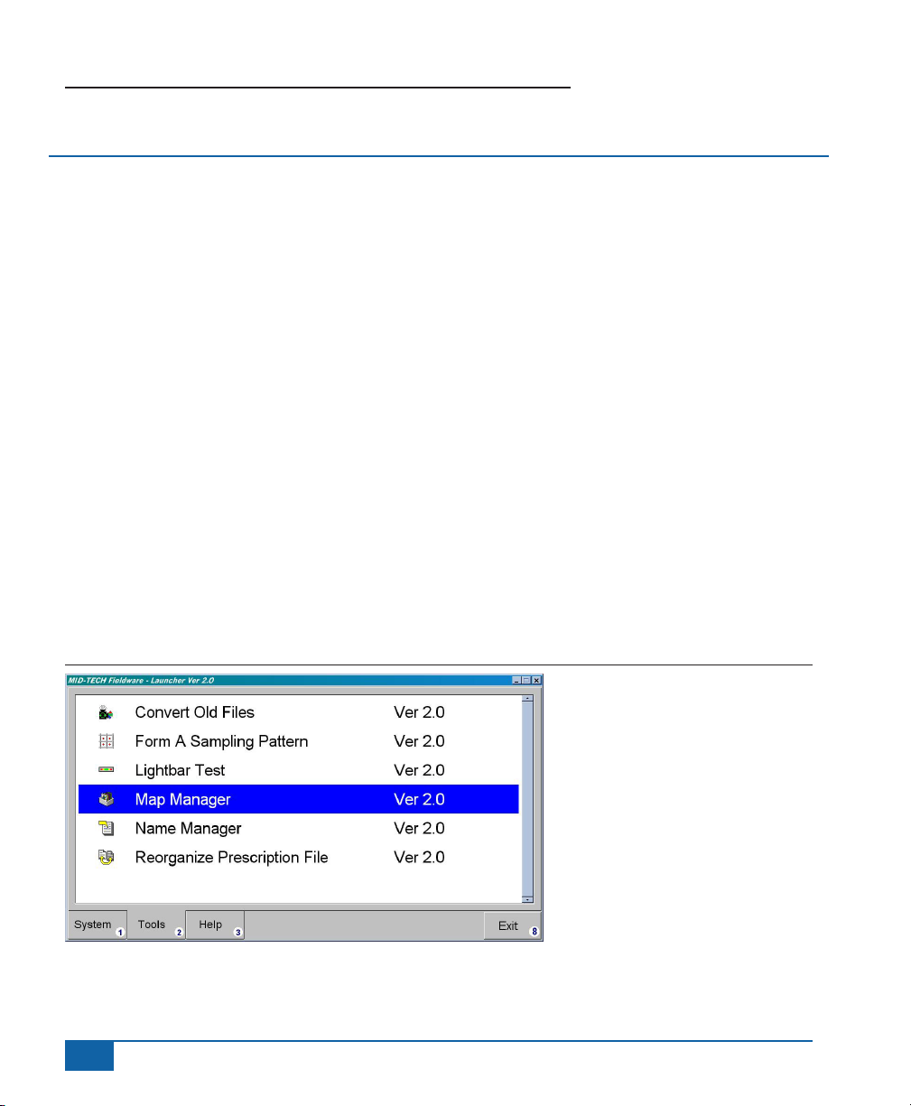
Fieldware Tools is a subset of TeeJet Technologies’ Fieldware suite. This chapter covers several utility
applications that will make your life a little bit easier. Currently Fieldware Tools consists of ve applications:
Convert Files, Form A Sampling Pattern, Map Manager, Name Manager, and Reorganize Prescription les. All
Fieldware Tools are accessed from the Fieldware Launcher Tools Menu.
Figure 1: Fieldware Tools Menu
iv
www.teejet.com
Page 5

Fieldware® Tools
MAP MANAGER
Map Manager is a data le viewing and conversion tool. The following Swath XL/GuideLine/Fieldware data les
can be viewed in the Map Manager:
• .GMF - General Mapping File
• .BND - Field Boundary File
• .RCD - Spray Trajectory and Application Rate Record File
• .RPT - Application Report File
• .GLN - Guideline File
The current version of Map Manager can view any combination of the above le types, as well as the following
les used only by Fieldware:
• .ARM - Prescription File
• .SPT - Marked Sample Points File
• .SHP - ESRI Shape File
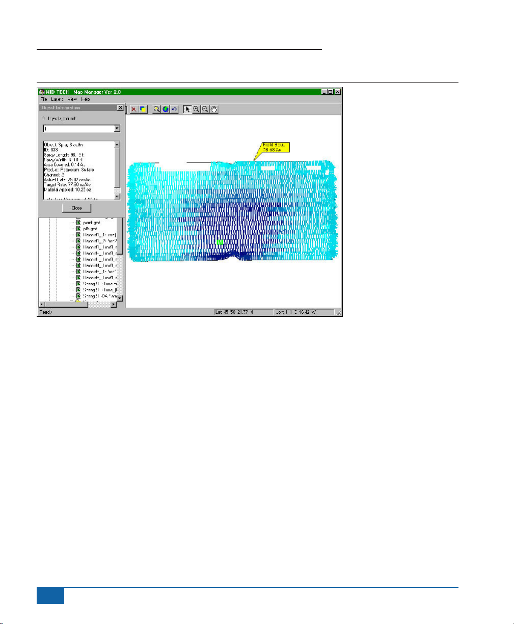
Map Manager also allows you to zoom, pan, and print the les displayed. (Figure 2) shows the a spray trajectory
record le, a boundary le, a hazard le, and the guideline le in a single Map Manager view. The left side of the
Map Manager window is the directory and le tree and the right side is the data viewing window. Data les are
loaded into the view window by double clicking on the le in the directory and le tree. You can view les from
different clients, farms, and elds within the same view window. Each map le that is loaded into the view page is
considered a single layer.
NOTE: Files created in fieldware programs are automatically given the “Client/Farm/field” format. Those created
in Swath XL & GuideLine products are not created in this format but can be stored that way using the
procedure described in Appendix A.
98-05048 R3
1
Page 6
Fieldware
Figure 2: Map Manager
®
Tools
2
www.teejet.com
Page 7
Fieldware® Tools
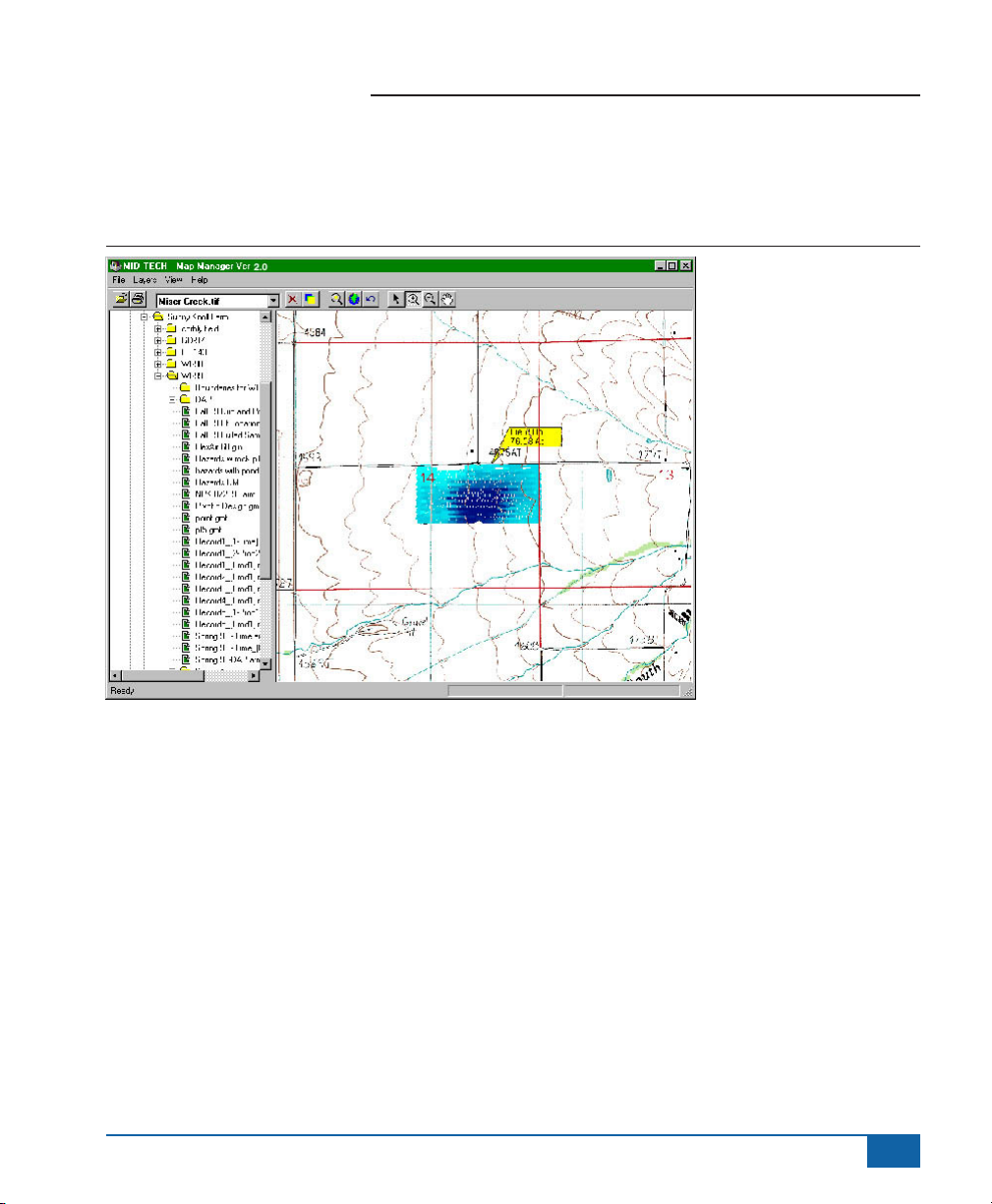
Base Maps
You can also view background base maps such as USGS topography maps in Geo-Tif formats. (Figure 3) shows
a base map behind an as-applied map.
Figure 3: Viewing Base Maps
98-05048 R3
3
Page 8
Fieldware
®
Tools
Color Prescription Maps
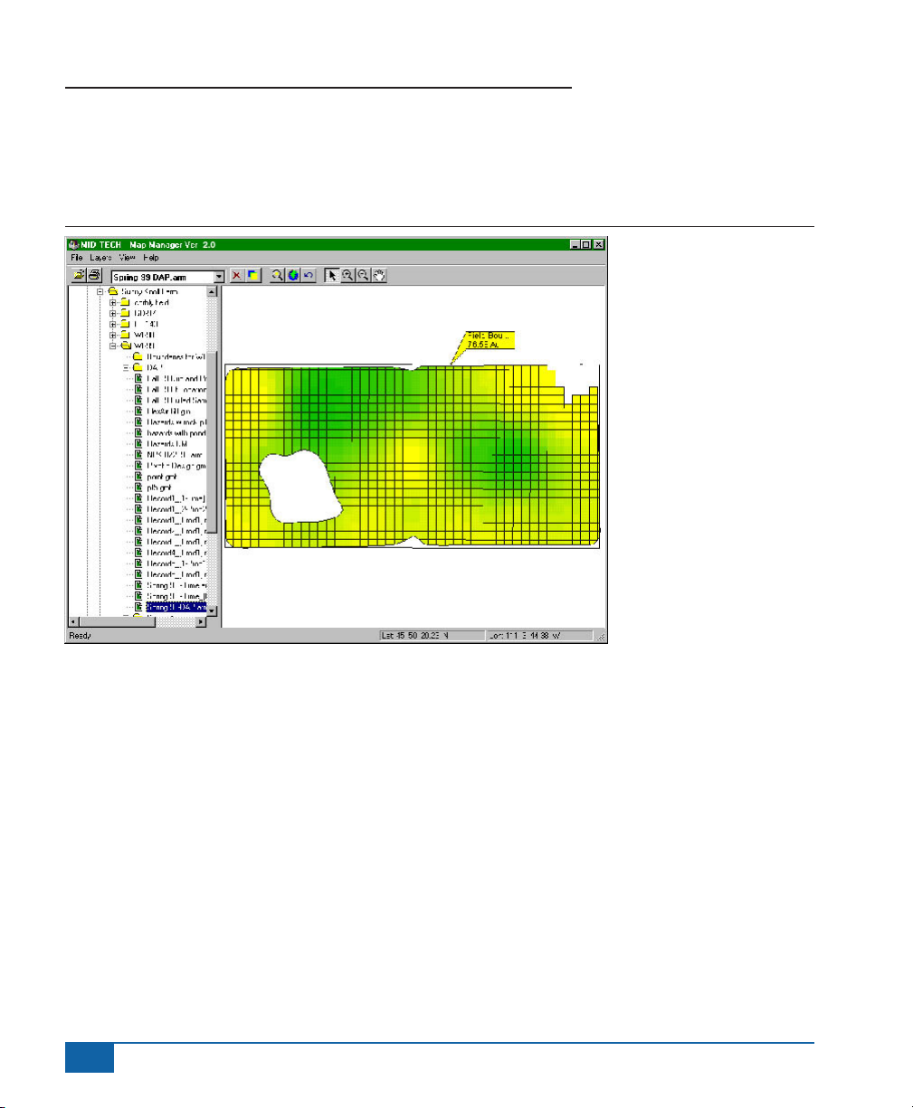
Map Manager now displays the Mid-Tech Application Rate Map (.ARM), a prescription map in color. (Figure 4)
shows an example of an (.ARM) prescription map displayed in Map Manager.
Figure 4: View of Prescription Map
4
www.teejet.com
Page 9
Fieldware® Tools
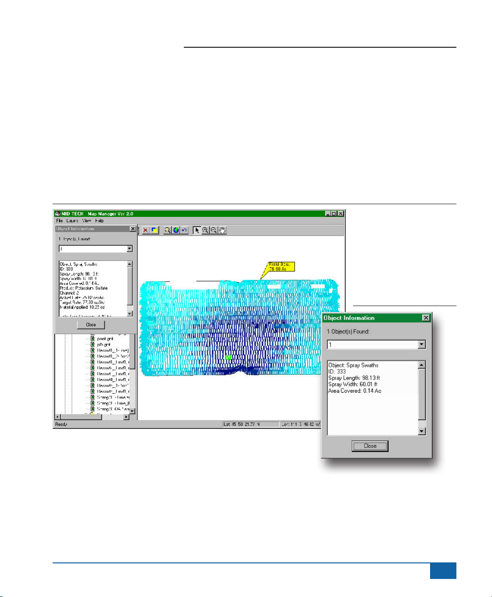
Object Information Query
It is possible to query any type of data that can be viewed in Map Manager. Using the pointer tool, select by
clicking on the area of the view you want to obtain information about. The area selected changes to a uorescent
green color and an “Object Information” dialog box appears on the left hand side of the Map Manager window.
The “Object Information” dialog box displays a variety of information about the object selected, such as position
and name. If the selected object is an application Record File (.RCD) you can query the individual polygons and
obtain information. (Figure 5) shows an information query on a Fieldware “as applied” map sprayed swath object.
(Figure 6) shows a close up of the “Object Information” dialog box for the sprayed swath query. If the area you
select has several objects layered one on top of the other, the “Object Information” dialog box displays the number
of objects selected as “Objects Found” and allows you to select and view information for each object.
Figure 5: Object Information Query Feature
Figure 6: Object Information
Dialog
98-05048 R3
5
Page 10
Fieldware
®
Tools
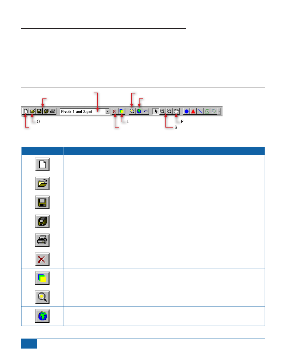
The Map Manager Tool Bar
The tool bar allows you to rapidly manipulate how the data is viewed in the window. Layers can be added and
removed from the view, as well as unloaded from the view. The current or active layer is considered to be the layer
that sits on top of all other layers. To remove or unload a layer, make it the current layer and click on the remove
current layer button. Only the current layer can be removed.
Figure 7: The Map Manager Tool Bar
Current (top) Layer Name Zoom to Current Layer Extents
File Saving Zoom to Extents
Open Existing File Layers On/Off Pan
New File (Layer) Remove Current Layer Select, Zoom
Table 1: Map Manager Tool Bar Button Descriptions
Button Description
New File (Layer) - creates an new le (layer) and places it at the current (top layer) in the
map view. You are prompted for the new le name.
Open Existing File (Layer) - you are prompted with an Open File dialog from which you can
select and open an existing le (Layer), which is placed at the top layer in the map view.
Drawing Tools
6
www.teejet.com
Save File (Layer) - save the current (top layer) in the map view.
Save All - saves all les (layers) displayed in the map view.
Print - prints the current map view with all visible layers.
Remove Layer - press to remove (not delete) current (top) layer from the view. This does
not delete the le.
Layers On/Off - brings up the layers On/Off dialog box. You can then turn layers on and off
from this dialog box.
Zoom to Current Layer - zooms to the data extents of the current (top) layer.
Zoom to Extent - zooms to the data extents which all visible layers are contained.
Page 11
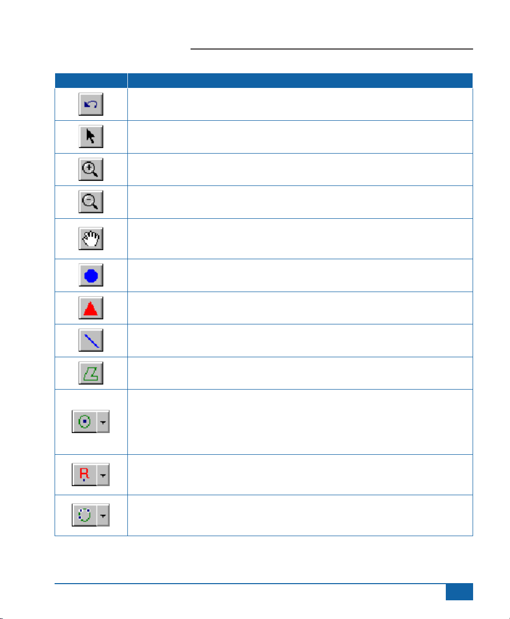
Button Description
Undo Zoom - returns to the previous zoom state.
Selection Arrow - activates the selection arrow (pointer).
Zoom In - enlarges (magnies) the map view. Two modes, drag box and point and click.
Zoom Out - increases area displayed in the map view. Two modes; drag box and point and
click.
Pan - select this button and then place hand in map view and hold down left mouse button.
Moving the hand with left mouse button depressed moves the contents of the map view in a
panning fashion.
Point Object - select this button and left click in the map view to place a point object in the
view.
Hazard Object - select this button and left click in the map view to place a hazard object in
the view. In real time applications the user is notied when approaching a hazard.
Fieldware® Tools
Polyline Object - select and draw a polyline in the map view. Double click the left mouse
button to stop drawing.
Polygon Object - select and draw a polygon object in the map view. Double click the left
mouse button to close and stop drawing the polygon.
Circle Tool (Drag Option) - select this and draw a circle by pressing and holding down the
left mouse button. Drag the mouse with left button depressed to create the desired radius,
release left mouse button to create circle object. Select and hold down left mouse button on
the circle tool and two other circle drawing options (Radius and 3-Point) appears in the drop
down tool.
Circle Tool (Radius Option) - select and click left mouse button at center location of desired
circle in the map view. A small Radius dialog box appears. Enter the desired circle radius
and click OK.
Circle Tool (3-Point Option) - select and click left mouse button on three different locations
you want the circle perimeter to intersect. Once the third point is selected, the circle is
drawn.
98-05048 R3
7
Page 12
Fieldware
®
Tools
MENUES
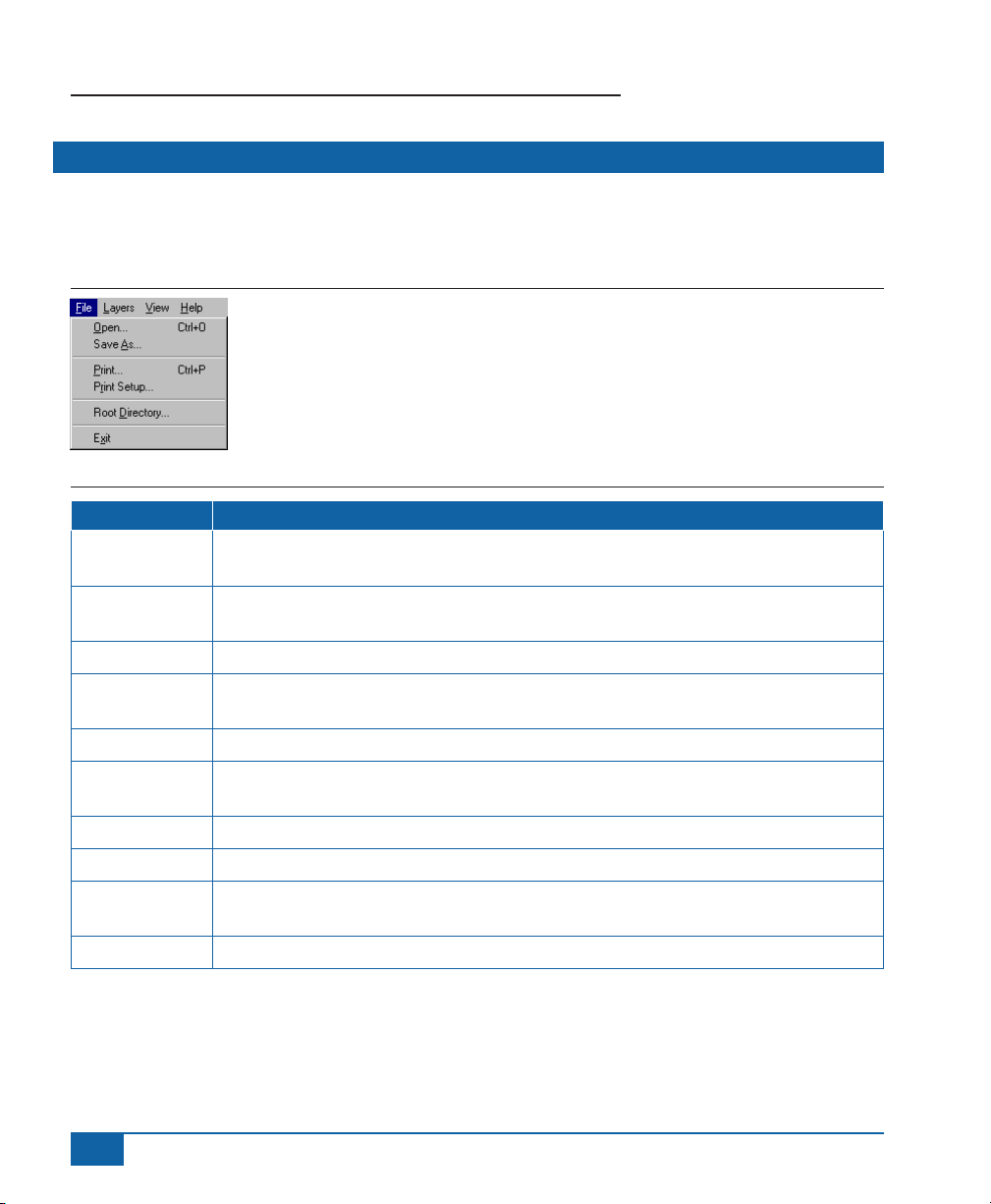
The File Menu
Almost all tool button functionality can be duplicated in one of the drop down menus. The File Menu allows you to
switch the root directory, print the view, set up the print view and exit the Map Manager tool (Table 2).
Figure 8: The File Menu
Table 2: Map Manager File Menu Item Descriptions
Menu Item File Menu Item Description
New
Open
Save Save File (Layer) - save the current (top layer) in the map view.
Save As
Save All Save All - saves all les (layers) displayed in the map view.
Convert
Print Prints the current map view with all visible layers.
Print Setup Sets up the print function.
Root Directory
Exit Select to Exit the Map Manager Program
New File (Layer) - creates an new le (layer) and places it at the current (top layer) in the
map view. You are prompted for the new le name.
Open Existing File (Layer) - you are prompted with an Open File dialog from which you can
select and open an existing le (Layer), which is placed at the top layer in the map view.
Saves current (top layer) le as a different le name. You are prompted with the Save As
dialog box.
Starts up the convert application which allows you to convert Fieldware data les to ESRI
shape les and vise-versa.
Select to change the root (highest level) folder displayed in the le tree on left hand side of
Map Manager.
8
www.teejet.com
Page 13
Fieldware® Tools
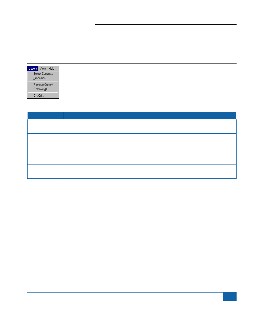
The Layers Menu
The Layers Menu allows you to manipulate and query information associated with a map layer in the map view
window (Table 3).
Figure 9: The Layers Menu
Table 3: The Layer Menu Item Descriptions
Menu Item Layer Menu Item Description
Select Current
Properties Activates the Layers Properties dialog box.
Remove Current
Remove All Removes all layers from the map view.
On/Off
Allows you to select the current (Top) layer. This can also be accomplished from the Tools
menu bar, see Table 1.
Removes current layer. This can also be accomplished from the Tools menu bar,
see Table 1.
Activates the Layers On/Off dialog box. This can also be accomplished from the Tools
menu bar, see Table 1.
98-05048 R3
9
Page 14
Fieldware
®
Tools
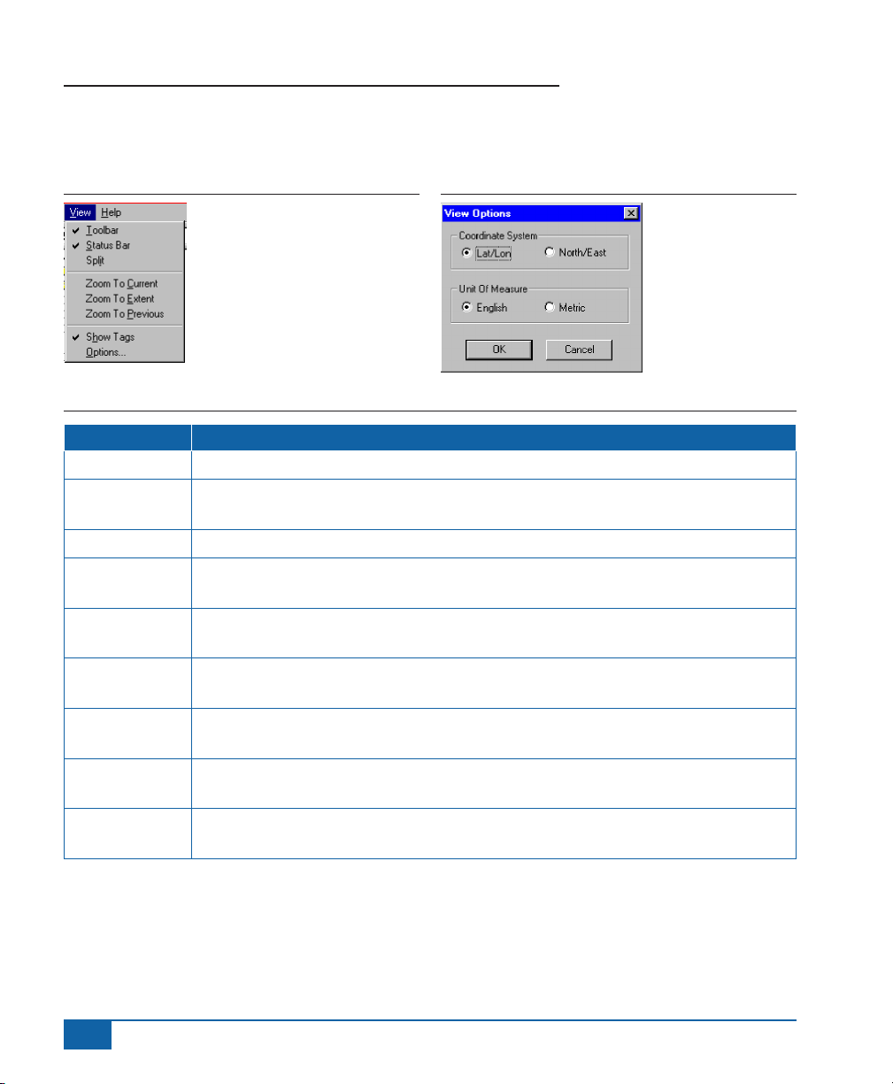
The View Menu
The View menu sets up the Map Manager window (Table 4).
Figure 10: The View Menu
Table 4: The View Menu Item Descriptions
Menu Item View Menu Item Description
Tool Bar Places or removes the Tool bar from the Map Manager window.
Status Bar
Split Activates the split screen function, allowing you to resize the map view and le tree.
Zoom to Current
Zoom to Extent
Zoom Previous
Show Tags
Options
Show All Files
Places or removes the Status bar from the bottom of the Map Manager window and
displays the current action as well as the real world coordinate position of the pointer.
Zooms to the current layers data extents. This can be accomplished from the tool bar,
see Table 1.
Zooms to the data extents which all visible layers are contained. This can be accomplished
from the tool bar, see Table 1.
Returns to the previous zoom state. This can be accomplished from the tool bar,
see Table 1.
Displays a small yellow tag next to each object in the map view. The tag contains
information about the object.
Brings up the Options dialog where the system units and coordinate system can be
changed, see (Figure 11).
When selected the le tree displays all le types. When de-selected, the le tree shows
only Fieldware le types.
Figure 11: The View Options Dialog
10
www.teejet.com
Page 15
Fieldware® Tools
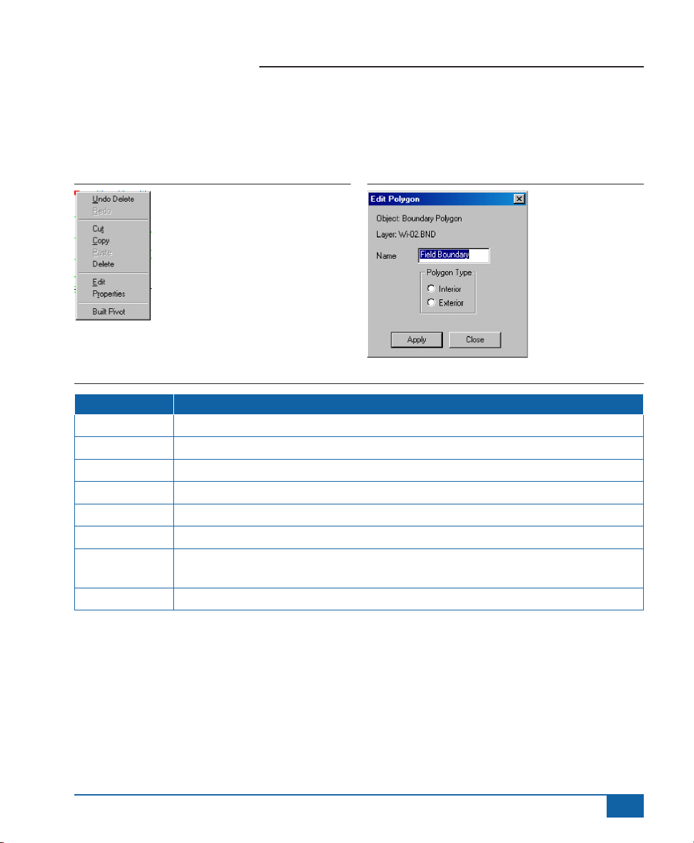
The Edit Menu
This drop down menu covers most graphical object editing functions such as cut, copy and paste (Table 5). Many
of the edit menu items can also be accessed by selecting an object in the map view and then pressing the right
mouse button.
Figure 12: The Edit Menu
Table 5: Edit Menu Item Descriptions
Menu Item Edit Menu Item Descriptions
Undo Delete Undoes a previously deleted object.
Redo Undoes a redo.
Cut Cuts a highlighted object from the view.
Copy Makes a copy of a highlighted object. To place the copy in the view, use paste.
Paste Pastes an object of a copy or cut object.
Delete Deletes a highlighted object.
Edit
Properties Displays the Object Information dialog, see (Figure 6).
Activates the Edit dialog box where object attributes such as object name can be modied.
(Figure 13) shows an edit dialog box for a boundary polygon object.
Figure 13: The Edit Box for a Boundary Polygon Object
98-05048 R3
11
Page 16

Fieldware
®
Tools
The Build Menu
This menu item activates the Prole Builder and the Report Builder. Build Proles allows you to construct various
data bases for Customer, Dealer, Applicator and Products. This data base information is used in the Build Report
application, see “The Build Prole Application” on page 16. The Build Report application allows you to generate an
application report based on an existing record (.RCD) le, see “Building an Application Report” on page 20.
Figure 14: The Build Menu Item
12
www.teejet.com
Page 17

Fieldware® Tools
THE BUILD PROFILE APPLICATION
The Build Prole application allows you to construct a set of small data bases specic to Dealer information,
Customer Information, Applicator information, and Product Information. These proles are used when building an
Application Report using the Build Report application.
Customer Prole
The Customer Prole allows you to enter customer information. This information can then be selected in Build
Report and printed as part of the Application report.
Table 6: Customer Profile Field Descriptions
Field Description
ID Customer Identication Code (Optional).
Name Customer Name (Required).
Address Customer Address (Required).
City/Town Customer City or Town Name (Required).
State/Prov Customer State or Province (Required).
Postal Code Customer Postal Code (Required).
Country Customer Country (Required).
Telephone # Customer Telephone Number (Required).
Contact Customer Contact Name (Optional)
Figure 15: The Customer Profile Dialog
98-05048 R3
13
Page 18

Fieldware
®
Tools
Dealer
The Dealer prole allows you to build a prole containing all of your dealer information. This information is then
used in the Build Report application.
Table 7: Dealer Profile Field Descriptions
Field Description
ID Dealer Identication Code (Optional).
Name Dealer Name (Required).
Address Dealer Address (Required).
City/Town Dealer City or Town Name (Required).
State/Prov Dealer State or Province (Required).
Postal Code Dealer Postal Code (Required).
Country Dealer Country (Required).
Telephone # Dealer Telephone Number (Required).
Contact Dealer Contact Name (Optional)
Figure 16: Dealer Profile Dialog
14
www.teejet.com
Page 19

Fieldware® Tools
Product
Fieldware Map Manager comes with a complete Product prole, approximately 4625 products. Each entry
includes the Product Name, Common Name, Formulation, EPA Registration # and Manufacturer. It is unlikely that
you will need to add any additional products to this prole. Prior to adding a new product to this prole, make sure
it is not already included. Updated Product Proles are available from Midwest Technologies Illinois, LLC. See
their web site for more information.
Table 8: Product Profile Field Descriptions
Field Description
Product Name The Name of the Product (Required).
EPA Reg # EPA Registration Number (Required).
Manufacturer The name of the product manufacturer (Optional).
Common Name The common name of the product (Required).
Formulation The product formulation, typically Liquid, Dry or Granular (Optional).
Figure 17: The Product Profile Dialog
98-05048 R3
15
Page 20

Fieldware
®
Tools
Applicator
The Applicator prole allows you to build a prole for each of your drivers. This information is then used in the
Build Report application.
Table 9: Applicator Profile Field Descriptions
Field Description
Employee ID Employee Identication Code (Optional).
Last Name Applicator’s last name (Required).
First Name Applicator’s First Name (Required).
SS# (SIN#) Applicator’s Social Security Number (SIN#) (Optional).
Drivers License Applicator’s drivers license number (Optional).
Applicators
License
Expiration date The expiration date of the Applicator’s license (Optional).
Supervisor The applicator’s supervisor (Optional).
Figure 18: Applicator Profile Dialog
Applicator’s applicator’s license number (Required).
16
www.teejet.com
Page 21

Fieldware® Tools
BUILDING AN APPLICATION REPORT
You can build an Application Report based on an existing record le (.RCD). The Build Report application utilizes
existing Customer, Dealer, Product and Applicator proles generated by the Build Proles application.
To build an application report it is recommended that you rst select and view the record le (.RCD) the report is
based on. You can also select and view the associated eld boundary (.BND) le. Viewing the (.RCD) and (.BND)
les are not required, but it is very useful to view this data prior to generating a report to ensure that they are the
correct les (Figure 19).
Once you have the data displayed in the map view window (right side) of Map Manager, select Report - Swath XL
/ GuideLine 3.0 from the Build menu located in the Map Manager menu bar, see “The Build Menu” on page 15.
Once selected, the Report Generation dialog appears.
Figure 19: Viewing Data Prior to Building an Application Report
The Report generation dialog contains ve tabbed setup dialogs, Maps/Files, Field Conditions, Product Setup, Job
Setup, and Document Setup. Building a report is easy if you select each tab in order starting from the left (Maps/
Files) and ending at the right most tab (Document Setup). Each tabbed dialog is described in more detail below.
98-05048 R3
17
Page 22

Fieldware
®
Tools
The Maps/File Dialog
In this report dialog you select the data les you want to base the report on. Each report is based on a single
record le. Therefore you can select one record le (.RCD), one boundary le (.BND) and several general
mapping les (.GMF).
Select the folder where the data is located using the Browse button. Relevant data les are displayed in the
Include in Report or Don’t Include windows in the dialog (Figure 20). To move a le between these two windows,
highlight the le you want to move and then press the direction of movement arrow located between the two
windows. A preview of the le is displayed to the right in the preview window. Once you have the desired les you
want to base the report on in the Include in Report window, you are ready to move to the Field Conditions dialog.
To move to the Field Conditions dialog, select the Field Conditions tab with the mouse.
Figure 20: The Build Report Maps/Files Dialog
18
www.teejet.com
Page 23

Fieldware® Tools
The Field Conditions Dialog
The Field Conditions dialog allows you to enter Weather, Soil, Crop, and Growth Stage information in the report
(Figure 21). Enter or select the appropriate Field Conditions. You can move from one data eld to the next by
pressing the Tab key on your keyboard. None of the Field Condition information is required to generate a report.
Once the desired Field Condition information has been selected, you are ready to move to the Product Setup
dialog. You do this by clicking on the Product Setup Tab.
Figure 21: The Build Report Field Conditions Dialog
98-05048 R3
19
Page 24

Fieldware
®
Tools
The Product Setup Dialog
The Product Setup dialog (Figure 22) allows you to enter information about the product(s) that were applied and
represented in the record (.RCD) le. In order to enter the appropriate product information, you must run the
Product Wizard. To start the Product Wizard, press the Product Wizard button located in the Product Setup dialog
(Figure 22).
Figure 22: The Build Report Product Setup Dialog
20
www.teejet.com
Page 25

Running the Product Wizard
Select the type of application you are doing
(Figure 23). Press the Green forward to move to the
next wizard page.
Figure 23: Product Wizard Application Type
Next select the number of products used in the
application (Figure 24).
Figure 24: Product Wizard Number of Products
Fieldware® Tools
Figure 26: Product Wizard Product Unit
Next enter the Product Application Rate, Total Amount
of product applied, or both (Figure 27)
Figure 27: Product Wizard Application Rate
Select the Product Name (Figure 25). This is the list of
products found in the Product Prole. You can press
the NEW button to go directly to the Prole Builder.
From there you can add or edit a product.
Figure 25: Product Wizard Product Name
Once the product name has been selected, press the
Green arrow and select the Product Unit (Figure 26).
If you have selected more than one product, the
Product Wizard cycles back through Product Name,
Unit, and Application Rate until all products are
identied. After all product information is entered,
the next Wizard page is based on the Application
Type selected in the rst Wizard page (Figure 23).
In this example a Liquid (Wet) product was selected.
Therefore the next Wizard page is Water Unit (Figure
28). If a dry application type was selected the water
(carrier) Wizard pages would not appear.
Figure 28: Product Wizard Water Unit
98-05048 R3
21
Page 26

Fieldware
Next enter the Water Application Rate, Total Amount of
Water applied, or both (Figure 29).
Figure 29: Product Wizard Water Rate
The Product Wizard is now complete. Press the Finish
bottom to return to the Product Setup dialog. You
should see your new product information displayed in
the table of this dialog (Figure 30).
Figure 30: Report Generation Product Setup
Completed
®
Tools
22
www.teejet.com
Page 27

Fieldware® Tools
The Job Setup Dialog
The Job Setup dialog (Figure 31) is where you can select Job related information you want included in the
Application Report. Dealer, Customer, and Application names are stored in their associated proles. If you need to
create or edit any of these elds, press the NEW button to launch the Build Prole application.
Figure 31: The Build Report Job Setup Dialog
The Document Setup Dialog
The last Build Report dialog is Document Setup (Figure 32). In this dialog you can select a Dealer logo (JPEG
& BMP formats) that will be included in the application report. The Build Report As button will let you name the
report and save it where you like, much like a Save As option in any Windows program. The Build Report button
(recommended) builds the report based on the name of the record (.RCD) le and save it in the same folder
that the record (.RCD) le is stored. The name of the report and where it will be saved is displayed in the Save
Path window. After one of the Build buttons is pressed, the Report View dialog is displayed showing you the nal
Application Report. From this dialog you can zoom and pan as well as print the report.
98-05048 R3
23
Page 28

Fieldware
Figure 32: The Build Report Document Setup Dialog
Figure 33: The Report View Dialog
®
Tools
24
www.teejet.com
Page 29

Fieldware® Tools
CONVERTING FILES USING MAP MANAGER
Map Manager contains a le option named Convert, which provides a means of transferring data between
Fieldware data les and ESRI Shape les. Convert was designed to be both exible and simple. It allows
beginning users to perform conversions in ve simple steps, while offering advanced users full control over the
data transfer process. To better understand how the Convert option works, we will examine the steps required to
convert a le. Later we will show how Convert may be used to perform custom data transfers.
The File Conversion Process
The le conversion process can be broken into the following 5 steps:
1. Select the le you wish to convert (the source).
2. Select the le you wish to convert to (the destination).
3. Select the type of objects you wish to transfer between the source and destination.
4. Select a template describing how the objects should be transferred.
5. Convert the le.
Each of these steps is discussed in greater detail below.
Step 1: Selecting The Source File
The source le contains data you would like to convert to a different format. Select the source le from Map
Manager’s main window. To select a source le, simply open the le using Map Manager’s “File|Open” option
or Map Manager’s le tree. You may open/view Swath XL/GuideLine les, Fieldware les or Shape les (.shp)
within Map Manager. Shape les must be in NAD83 or WGS84 Lat/Long coordinates. No
other projections or datums are supported. ESRI shape les consist of .shp, .shx, and
.dbf les, all sharing the same le name. Shape les appear as simple line drawings in the Map
Manager Map. If you choose to open multiple les, the current le (layer) is used as the source le. After selecting
a source le, choose the “File|Convert” option. In (Figure 34), a prescription le named Spring 99-DAP.arm has
been selected as the source le and the “File|Convert” option is being selected. When the “File|Convert” option
is chosen, the Convert dialog is presented. Your source le’s name appears in the dialog’s Source group and the
source le’s image appears in the dialog’s Map (see Figure 35).
98-05048 R3
25
Page 30

Fieldware
Figure 34: Selecting Convert from File Menu
Figure 35: The Convert Dialog
®
Tools
Source File
Source File Image
26
www.teejet.com
Page 31

Fieldware® Tools
Step 2: Selecting The Destination File
The destination le holds objects and data converted from the source le. Unlike the source le, it is selected
from within the Convert dialog. To select a destination le, press the Save As button in the Destination group. A
standard Save As dialog appears. Specify the full name and extension of the destination le in the Save As dialog.
The destination must be a new le with one of the Save as types. Therefore, existing les may not be selected.
Once you have entered a lename, press the Save button. The destination le you specied appears in the
Destination group. In addition, the “Object Combo” box and Template group are activated. In (Figure 36) we have
selected Spring 99-DAP.arm as the destination le. As can be seen, the “Object Combo” box and Template group
are no longer grayed out.
Step 3: Selecting The Type Of Objects To Convert
Both Shapeles and Fieldware les contain objects such as Points, Polylines, and Polygons. Where Fieldware
les such as the GMF or BND le can contain several object types per le, Shapeles are limited to just one type
per le. Therefore, when we convert Fieldware les to or from Shapeles, we must convert one object type at
a time. For example, suppose we have a BND le containing Boundary Polygons, Polylines, and Points. Let’s
assume that we wish to convert this le to a Shapele. Given that the Shapele can only hold one type of object,
we must specify whether we want to pass it Boundary Polygons, Polylines, or Points. We select which type of
object to transfer via the “Object Combo” box. The “Object Combo” box provides a list of available Fieldware le
objects for us to choose from. If the source le is a Fieldware le, the “Object Combo” box contains the list of
objects in the Fieldware le. If the Fieldware le is the destination le, the “Object Combo” box contains the list of
objects accepted by the Fieldware le which may be attained from the Shapele. When you select a destination
le, the “Object Combo” box activates and presents you with a default object type. If the type is not acceptable,
select one of the other object types from the “Object Combo” box’s list. When you select a new object type, the
template list is updated to reect the list of available templates matching the type. In (Figure 36), we have chosen
to accept the default (and only available) object type: Prescription.
98-05048 R3
27
Page 32

Fieldware
Figure 36: Completed Convert Dialog
File Destination
Object Combo Box
Template Group
®
Tools
Step 4: Selecting A Template
A template is essentially a set of instructions for transferring the selected object type to, or creating the selected
object type from a Shapele. The Convert Dialog provides us with a list of available templates for the conversion
we have selected and allows us to manage the templates using the New, Delete, and Edit buttons (when
converting a .shp le for the rst time you are required to create a template.) In the next
section,“Field Transfer Templates” on page 34, we will discuss templates in greater detail. However, for now, let’s
just accept that we must select a template from the provided list. In (Figure 36) we have selected the Prescription
To SHP template.
28
www.teejet.com
Page 33

Fieldware® Tools
Step 5: Converting The File
Before converting the le, we should discuss the “Remove Layer From Map” check box located in the Source
group and the “Add Layer To Map” check box located in the Destination group. These settings determine what
happens to the source and destination les after the conversion has completed and the Convert dialog is removed
from the screen. The “Remove Layer From Map” check box species whether the source le (the current layer)
should be removed from the Map Manager map. The “Add Layer To Map” check box species whether the
destination le should be added to the Map Manager Map. If both boxes are checked, as in (Figure 36), the
source le is replaced by the destination le as Map Manager’s current layer.
You are now ready to press the Convert button and set the data transfer in motion. Once the button is pressed,
the Info bar begins displaying status information. If a problem is encountered, an error message is presented. If no
error occurs, the Convert dialog is removed from the screen and the Map Manager map is updated. (Figure
37) shows: (a) Spring 99-DAP.arm was converted to Spring 99-DAP.shp; (b) Spring 99-DAP.arm was removed
from the Map Manager map; (c) Spring 99-DAP.shp was added to the Map Manager map.
Figure 37: The Converted Spring 99-DAP.SHP Map
98-05048 R3
29
Page 34

Fieldware
®
Tools
FIELD TRANSFER TEMPLATES
As was mentioned earlier, a template contains the information required to transfer an Fieldware le object to
an object in a Shapele, or create an Fieldware le object from an object in a Shapele. To better understand
templates, we must rst understand the data which makes up an Fieldware le or Shapele object. An object
(Polygon, Polyline, Point) is just a shape (one or more positions) with an associated set of attributes or elds. The
shape’s elds specify information about the shape such as its name or ID. The shapes stored in a Fieldware le
and Shapele objects are essentially the same. However, the elds associated with the shapes are different. In
order to transfer the contents of an Fieldware le object to or from a Shapele object we must specify how the
Fieldware le object’s elds are mapped or transferred to the Shapele object’s elds. It is the template which
stores these eld transfers. Fieldware les can contain one or more object types where .shp
les can only be a point, a polyline, or a polygon. To convert a .gmf le to .shp where the .gmf le
contains points and polygons, you would run the conversion twice, once to make the point shapele and again to
make the polygon shape le.
Figure 38: Converting To A Shape File
If you experiment with the Convert dialog, you will notice that different templates are displayed for different
combinations of the source le, destination le, and object type. This is because the elds for each Fieldware
object type of Shapele are unique. The Convert dialog only displays templates which make sense for the
selected les and object type. Under some circumstances, no templates are displayed because none of the
existing templates contain appropriate eld transfers. You may have discovered that the a template named < None
> is often included in the Template list (see (Figure 38)). This template is exactly what its name implies, a template
30
www.teejet.com
Page 35

Fieldware® Tools
that doesn’t contain any eld transfers. When a le is converted using this template, only the shape portion of
objects is passed between the source and destination les. No attribute or eld information is transferred. If
you want to create a prescription le (.arm), do not use the <NONE> template. Convert
dialog does not allow the <None> template to be deleted or edited.
Sooner or later you will probably run across a situation which requires you to create or modify a template.
Templates are managed using the New, Delete, and Edit buttons located in Convert dialog’s Template group (see
(Figure 38)). To create a new template press the New button. You are presented with the Field Transfer Template
dialog (see “Setting Up A Field Transfer Template” on page 36). To delete the current template (the template
whose name appears above the list) press the Delete button. You are presented with a message box that asks
you to conrm the delete. If you are sure you want to delete the template, press the Yes button. Otherwise press
No. If you wish to edit the current template, press the Edit button. You are presented with the Field Transfer
Template dialog (see “Setting Up A Field Transfer Template” on page 36).
Figure 39: The Field Transfer Template
Field Transfer List
98-05048 R3
31
Page 36

Fieldware
®
Tools
Setting Up A Field Transfer Template
In (Figure 39) we see the “Field Transfer Template”
dialog. This dialog is used to set up a eld transfer
template. At the top of the dialog is the “Template
Name” edit box. Templates should be given a unique
name which identies the type of conversion they are
meant to handle. In (Figure 39), the template has been
named “Point to SHP”, identifying that this template
should be used for Fieldware Point object to Shapele
object conversions.
Below the “Template Name” edit box is the Field
Transfer list. This list contains the eld transfers or
mappings that will be performed between the given
source le and destination le objects. The elds of the
source le object are presented in the list’s left-hand
column and the elds of the destination le object are
presented in the list’s right-hand column. In (Figure 39),
we are mapping the Fieldware Point object’s NAME
eld to the Shapele object’s SHP_NAME eld and
the Fieldware Point object’s ELEVATION eld to the
Shapele object’s ALTITUDE eld.
The New, Edit, and Delete buttons to the right of the
Field Transfer List are used to change the entries in
the list. To create a new eld transfer, press the New
button. You are presented with the Field Transfer dialog
(see “Conguring A Field Transfer” on page 37). To
delete the current eld transfer (the transfer currently
highlighted in the list), press the Delete button. You are
presented with a message box that asks you to conrm
the delete. If you are sure you want to delete the
transfer, press the Yes button. Otherwise press No. If
you wish to edit the current eld transfer, press the Edit
button. You are presented with the Field Transfer dialog
(see “Conguring A Field Transfer” on page 37).
Several buttons in the Field Transfer Template dialog
only appear if you are transferring elds from an
Fieldware le to a Shapele. The Up/Down Arrow
buttons allow you to change the order of eld transfers
in the list. The order of the transfers determines the
order in which elds are written to the Shapele. In
(Figure 39), the SHAPE_NAME eld precedes the
ALTITUDE eld in the resulting Shapele. The Copy All
button copies all the elds in the Fieldware le object to
the Shapele object. Press this button if you want your
Shapele object to contain an exact copy of the elds
in the Fieldware le object.
Figure 40: The Field Transfer Dialog
32
www.teejet.com
Page 37

Conguring A Field Transfer
In (Figure 40) we see the Field Transfer dialog. This
dialog is used to congure a single eld transfer.
The left-hand portion of the dialog denes a source
eld which will be transferred to the destination eld,
dened to the right. Each eld setting on the left is
followed by an arrow button and a matching eld
setting on the right. When active, the arrow button may
be used to transfer the contents of the left setting to
the right. Pressing the Copy button at the bottom of the
screen is equivalent to pressing all of the active (not
grayed out) arrow buttons.
The top pair of settings are used to dene the names
of the elds. These settings may take the form of a
combo box or an edit box. If a combo box is present,
you may select one of the names from its list. The
list contains all the names located in or compatible
with the eld. If an edit box is present you must type
in the name of the eld. In (Figure 40), we selected
ELEVATION as the source eld’s name and entered
ALTITUDE as the destination eld’s name.
The second pair of settings dene the eld’s types.
These settings take the form of either a combo box or
a text box (can’t edit). If a combo box is present, you
may select the type you wish to associate with the
eld. This affect how the eld is written to the le when
the conversion is performed. If a specic TYPE
is listed in the box on the left it is best to
chose the same for the box on the right.
In (Figure 40), we selected Double as the destination
eld’s type.
Fieldware® Tools
Figure 41: The Build A Unit Of Measure Dialog
The nal pair of settings assign units of measure to
the elds. These settings take the form of either a
combo box or a text box (can’t edit). If a combo box
is present, you may select the unit of measure the
eld is (or will be) stored in. Take care in selecting a
unit of measure. If the eld denes a name or some
other non-numeric value, specify <None> for the
unit of measure. If you don’t know the eld’s unit
of measure, select <Unknown>. When the eld is
transferred, all necessary unit of measure conversions
are automatically performed. Therefore, it is important
that the source eld’s and destination eld’s units
of measure are compatible. If you have entered
incompatible units of measure, you are presented
with an error when you press OK. In (Figure 40), we
selected feet as the destination eld’s unit of measure.
If the Unit Of Measure setting has a Browse button to
its right, you may opt to build a unit of measure for the
eld. Pressing the button brings up the Build Unit Of
Measure dialog (see (Figure 41)). This dialog allows
you to select or compose a UOM (unit of measure)
from a long list of options. If you wish to select a UOM
from the list, you may type the UOM’s name in the
“Unit Of Measure” edit box or nd the UOM in the list.
98-05048 R3
33
Page 38

Fieldware
®
Tools
You can compose new compound UOMs (such as
pounds/acre) by separating UOMs in the list with a ‘/’.
Pressing the “/ (Per)” button adds the ‘/’ for you. If you
make a mistake, you can simply click the Clear button
or erase the text in the “Unit Of Measure” edit box.
When you select OK, your UOM is passed to the Unit
Of Measure setting.
Figure 42: User Defined Fields
Under some circumstances, the Field Transfer
dialog’s appearance undergoes some changes. One
such circumstance arises when we set the source
eld’s name to <CONSTANT> or <COUNTER>.
<CONSTANT> and <COUNTER> are special
user-dened elds. They do not exist in the source
le object. If you set the source eld name to
<CONSTANT>, the source eld’s Type setting is
replaced by a Value setting, (Figure 42). The Value
setting is a string or number that is passed to the
specied destination eld for each object written to
le. If you set the source eld name to <COUNTER>,
the source eld’s Type setting is replaced by a First
Number setting. As its name implies, the First Number
setting represents the counter’s starting value. Each
time the counter value is transferred to the specied
destination eld, it increments by one. For example,
if we were to set the First Number to 2, the specied
destination eld would receive a 2 for the 1st object, a
3 for the 2nd object, a 4 for the 3rd object and so on.
The Field Transfer Dialog also undergoes a change
when dealing with Fieldware prescription elds. As can
be seen in (Figure 43), two additional settings must
be congured for prescription elds. The two extra
settings are Product Type and Product Name. Product
Type takes the form of either a combo box or a text box
(can’t edit). If a combo box is present, you may select
the type of product being applied. Product Name takes
the form of either an edit box or a text box (can’t edit).
If an edit box is present, you may enter the name of the
product being applied.
Templates are a complex, yet powerful tool. Creating
templates takes some practice. However, once you get
the hang of it, you should be able to perform an almost
limitless array of Fieldware/Shapele conversions.
Figure 43: Prescription Map Conversion In Field
Transfer Dialog
34
www.teejet.com
Page 39

Fieldware® Tools
ABOUT FORM A SAMPLING PATTERN
The Form a Sampling Pattern program allows you to create, align, and rotate a sampling grid layer over
any existing data collected with Mid-Tech Fieldware software, such as a eld boundary. Once the grid is
properly oriented over the background data, sample point locations can be included with the grid based
on several sample pattern options. This grid and point information can then be used in conjunction with the
Fieldware - Sample & Waypoint Navigation and Fieldware - Field Mapping, Swath XL and GuideLine products.
Figure 44: Starting Form A Sampling Pattern From The Launcher
98-05048 R3
35
Page 40

Fieldware
QUICK START
Select Form a Sampling Pattern from the Program Launcher Tools menu, or double click
on the Form a Sampling Pattern icon in the Windows Explorer. The Receiver Process is not
required for this program.
From the Main menu in the Setup page, enter the appropriate Client, Farm and Field
information. For fast entry you may select the default Client, Farm, Field information that is
presented. Save this information in a Setup le.
Enter a background le name in the Background le menu eld. Typically this is the
boundary le (.BND) for the eld that you are creating a sampling pattern for.
Enter the output le name in the Output File menu eld. The grid and associated point
positions will be stored in this le.
Move to the Grid Menu page by pressing the GRID tab.
Store Grid menu eld, enter YES if you want the nal grid stored in the output data le.
Enter NO if you do not want to store the grid.
Store Points menu eld, enter YES if you want to store the sample points in the output le.
Enter NO if you do not want to store any points
Select the type of point sampling pattern.
Enter the grid cell size, either by area or height and width.
To save this information in the Setup le, press the SAVE button. To continue to the next
step press the NEXT button.
Orient the sampling grid using the rotation buttons and the shifting arrows.
Once the sampling grid is in the desired rotation, press the NEXT button to move to the
Sample points page.
®
Tools
36
www.teejet.com
In the Sample Points page, edit, add, or delete any points. Once satised with sampling
pattern press the FINISH button.
Page 41

Fieldware® Tools
THE SETUP PROCESS USING MENU PAGES
There are two Setup menu pages associated with this program, the Main page and the Grid page. It is important
to understand each menu item in each page in order to fully utilize this program. Each Setup page is identied by
the page tab located at the bottom of the Setup menu window. To move from one page to another, press the page
tab using the associated Function key or the mouse. There are three additional buttons located at the bottom right
of the Setup menu window: EXIT, SAVE and NEXT. EXIT returns you to the program launcher or the Windows
desktop. SAVE saves all menu page information in the Setup le that you select on the Main menu page. NEXT
brings you to the Orient Sample Grid page.
Navigation through all of the menu items is accomplished using the up and down arrow keys located on your
computer keyboard, or via a mouse.
The Main Setup Page
The main setup page contains seven menu elds all pertaining to le information required to properly
run this program.
Client-Farm-Field Menu Fields
As mentioned in the Map Manager introduction section of this user’s guide, les and data adhere to the Client/
Farm/Field pattern. The rst three menu elds relate to this pattern, allowing you to better manage and organize
your data. (Figure 45) shows the Main setup page with all menu elds selected. Once the Client-Farm-Field menu
elds are selected, the next menu eld entry is the Setup le.
Setup File Menu Field
The Setup File eld contains the name of a le that will hold all menu item entries for the two menu pages, Main
and Grid. A suggestion for naming the setup le is by the task being performed. As an example, in (Figure 45),
the task is building a sampling pattern for the Fall 1999 sampling campaign. Therefore the Setup and Output
le names are “Sample Pattern 99.d” and “Sample Pattern 99.gmf”. When adopting this naming convention, it
becomes easier to identify which Setup le was used for which task.
Background File Menu Field
The Background File menu eld should contain the data set that you want to design a sampling pattern on.
Typically this would be the boundary le (.BND) for the eld.
Output File Menu Field
The Output le is the le that will contain the sampling pattern data that you design. Typically this would be the
sample point locations and the sampling grid. The Output le must be a new le each time you build a sampling
pattern. If you enter the name of an existing le, you will not be allowed to store a sampling pattern in that le.
98-05048 R3
37
Page 42

Fieldware
Figure 45: Main Setup Page
®
Tools
The Grid Setup Page
Pressing the GRID tab brings up the Grid Setup page. The Grid Setup page allows you to customize
the sample pattern design, by selecting the type of pattern as well as the sample grid cell size.
Store Grid Menu Field
This menu item allows you to include the sampling grid in the Output le, by selecting YES. If NO is selected, then
the sampling grid is not stored in the Output data le.
Store Points Menu Field
Similar to the previous menu eld, you can elect to store the sample points in the Output le by setting this eld
to YES. If you select NO in this menu eld, the sample points are not stored in the Output data le. Typically you
would store sample points in the Output data le. If you are interested in only generating a sample grid with out
sample points then you would set this menu eld to NO.
Sampling Pattern Menu Field
The Sampling Pattern menu eld allows you to select a point distribution pattern from several sampling pattern
options: Regular, Staggered, and Unaligned. The pattern that you select directly affects where a sample point is
positioned within a grid cell. If the pattern REGULAR is selected, then a sample point is positioned at the center
of each sample grid cell. A STAGGERED pattern positions points in an alternating fashion, centering a point in
one cell and in the next cell positioning a point in the center of the lower cell boundary. The UNALIGNED pattern
38
www.teejet.com
Page 43

Fieldware® Tools
positions points in a random fashion across a gridded eld boundary ensuring that a point falls within each cell.
(Figure 46) shows the “Sampling Pattern” selection box. This menu eld is only active if the Store Points menu
eld is set to YES. Notice the pattern selected in (Figure 47) is Regular.
Figure 46: Sample Pattern Selection Box.
Cell Area Menu Field
The Cell Area menu eld allows you to enter the size of a sample grid cell. The cell area unit is based on the
System Unit of Measure selected in the System Setup menu. If the System Unit of Measure is ENGLISH (US
English), then the cell area unit is Acres. If the System Unit of Measure is METRIC, then the cell area unit is
Hectares. In the example shown in, the System Unit of Measure is ENGLISH, and therefore the Cell Area value is
5.00 Acres. As you enter a cell area value you will notice that the two additional Cell menu elds (Cell Horizontal
and Vertical Length) adjusts accordingly.
NOTE: Grid cells created using this menu field generate square sample grids only. To create non-square grid
cells, use the following two menu fields.
Cell Horizontal and Vertical Length Menu Fields
These two menu elds allow you to create non-square grid cells by entering the horizontal and vertical lengths.
The unit of length is based on the System Unit of Measure set in the Program Launcher System menu page. If
ENGLISH is selected, then the lengths are in Feet, and if METRIC is selected then the length unit is Meters.
98-05048 R3
39
Page 44

Fieldware
Figure 47: The Grid Setup Page
®
Tools
Completing the Setup Process
Once all of the appropriate menu elds have been entered or selected, the
next step is to save these entries. To save all of the setup menu entries
press the SAVE button at the bottom of the setup menu page. When SAVE
is pressed, all of the menu items are stored in the Setup le found in the Main Setup page. If you need to exit the
program process at anytime or you want to resume generating a sample pattern with the same menu items
selected, you may select the appropriate existing Setup le name and all of the menu items are lled in with the
appropriate data.
At this point you may exit the Setup process by pressing the EXIT button or you may go to the Sample Grid
Placement page by pressing the NEXT button.
Orienting the Sample Grid
Once the Setup menu pages have been properly entered, then next step is to orient the sample grid
over the background data. To begin this step press the NEXT button at the bottom of the Setup
menu Page.
Pressing NEXT brings up the Orient Sample Grid page which should show the background le with a sample grid
placed over the top, (Figure 48). This page allows you to rotate and shift the sample grid prior to positioning the
sample points within the sample grid.
40
www.teejet.com
Page 45

Figure 48: The Orient Sample Grid Page
Background data
of eld boundary
Sampling Grid
Grid shift buttons
Rotation angle
Grid rotation
buttons
Fieldware® Tools
Rotating the Grid
The sample grid can be rotated by either of two methods. The rst method is to enter the desired rotation angle
and the second method is to “spin” the grid in a left or right direction to the desired rotation angle. The point of
rotation for the grid is located at the center of the background data set.
Rotating the grid by entering a rotation angle
To rotate the grid by entering a rotation angle, press the button shown to the left. Once pressed, a
“Rotation Angle” dialog box appears. Enter the desired angle and press Enter. The grid rotates in a
clockwise direction from North, or straight up the page. To reset the grid, enter a rotation angle of 0.
(Figure 49) shows the “Grid Rotation” dialog box.
Figure 49: The Grid Rotation Dialog Box.
98-05048 R3
41
Page 46

Fieldware
®
Tools
Rotating the grid using the “Spin” buttons
A second method to rotate the grid is to spin it using the two SPIN buttons shown in the
column to the left. This method works best when you are attempting to visually line the
grid up with a feature in the background data le such as the edge of the eld
boundary. Pressing either of these buttons rotates the grid in the direction indicated by the arrow on the button. As
you press one of these buttons, the grid spins and the rotation angle is displayed in the information bar located
near the bottom of the page.
Shifting the Grid
Orientating the grid also includes shifting the grid. You may like the orientation angle of the grid but need to align
a row or column of grid cells along an edge of a eld boundary. There are two methods to shift the grid, using the
shift buttons or by using a mouse.
Shifting the grid using the shift buttons
You can shift the grid by using the four Shift buttons located to the right and bottom of the Orient Grid
page. These buttons, shown to the left, can be activated by pressing the arrow keys located on your
computer keyboard, or by pressing them with a mouse. As you press these buttons the grid moves in
the direction indicated by the blue arrow located on the button.
Shifting the grid using the mouse
To shift the grid using a mouse, move the mouse pointer over the grid. Hold the left mouse button down and drag
the grid to the desired position.
Completing the Grid Orientation
Once you have oriented the sample grid to your satisfaction, the next step is to position the sample
point locations based on the sample pattern selected in the setup process. To move to the Position
Points page, press the NEXT button.
This completes the grid orientation process.
42
www.teejet.com
Page 47

Fieldware® Tools
Positioning the Sample Points
After the grid orientation process is complete, the next step is to position the sample points within the grid.
Pressing the NEXT button in the Grid Orientation page brings you to the Position Points page (Figure 50).
Figure 50: The Position Sample Points Page
Sampling Grid
Sample Points
Editing Cursor
Field Boundary
Button Bar
The sample points are distributed within the sample grid based on the Grid Setup menu selections. In (Figure 50),
the grid menu selections were 5.0 Acre square grids and the point sample pattern was REGULAR. The grid had
been oriented to align with the South and West edges of the eld boundary.
The Position Point page allows you to perform some basic point editing tasks such as deleting and adding points.
You can also select a point and enter a specic point name as an attribute. Points can be selected by positioning
the Red editing cursor over a point. The editing cursor can be positioned using the arrow keys located on your
computer keyboard, or by using the mouse. To add a point, position the editing cursor over the desired location
and press the ADD button. To delete a point, position the editing cursor over the point you want to delete and
press the DELETE button.
Once you are satised with the sample point distribution with in the sample grid, press the FINISH button to
complete the Form a Sampling Pattern process.
98-05048 R3
43
Page 48

FIELDWARE® TOOLS
USER MANUAL
1801 Business Park Drive
Springeld, Illinois 62703 USA
Tel: (217) 747-0235 • Fax: (217) 753-8426
www.teejet.com
98-05048 R3
© TeeJet Technologies 2011
 Loading...