

Page 1
98-05112 R4
Page 2

TABLE OF CONTENTS
CHAPTER 1 INTRODUCTION ................................................................................................................................................3
System Conguration .......................................................................................................................................................4
Installation - Guidance ......................................................................................................................................................4
Installation - SmartCable..................................................................................................................................................5
CHAPTER 2 SETUP ...................................................................................................................................................................7
Power Up Sequence ..........................................................................................................................................................7
Area Reset ..............................................................................................................................................................................8
Setup Mode ..........................................................................................................................................................................8
Initial Setup Screen ..........................................................................................................................................8
Delay On .......................................................................................................................................................... 8
Delay Off .......................................................................................................................................................... 9
Overlap ............................................................................................................................................................ 9
Number Of Boom Sections .............................................................................................................................. 9
Boom Section Widths ...................................................................................................................................... 9
Boom Offset Direction ....................................................................................................................................10
Boom Offset Distance .................................................................................................................................... 10
Assisted Steering Setup Mode .................................................................................................................................... 10
Steering ......................................................................................................................................................... 10
Look Ahead .....................................................................................................................................................11
Aggressiveness ..............................................................................................................................................11
Valve Gain ......................................................................................................................................................11
Sensitivity ........................................................................................................................................................11
Valve Test ...................................................................................................................................................... 12
Tilt Gyro Setup Mode ..................................................................................................................................................... 12
Tilt Gyro ......................................................................................................................................................... 12
Antenna Height .............................................................................................................................................. 13
Level One ...................................................................................................................................................... 13
Level Two ....................................................................................................................................................... 13
Final Tilt Calibration Screen ........................................................................................................................... 13
Display Setup Mode........................................................................................................................................................ 13
Display Setup Screen .................................................................................................................................... 13
Display Brightness ......................................................................................................................................... 13
Display Contrast ............................................................................................................................................ 14
Display Background ....................................................................................................................................... 14
LED Spacing .................................................................................................................................................. 14
COM Port Setup ........................................................................................................................................... 14
GPS Setup ..................................................................................................................................................... 14
CenterLine 230BP
98-05112 R4
i
Page 3

CHAPTER 3 OPERATION ..................................................................................................................................................... 15
Power Up Sequence ....................................................................................................................................................... 15
CL230BP Operation Reference Screens ................................................................................................................... 15
Navigation Screen - Mark A-B ....................................................................................................................... 15
Navigation Screen - Operation ...................................................................................................................... 16
Guidance Screen - Map Page ....................................................................................................................... 16
Auto Boom Section Control Screen ............................................................................................................... 16
Bounded Area Screen .................................................................................................................................... 16
Applied Area Screen ...................................................................................................................................... 16
Operation Function Keys ...................................................................................................................................... 17
Operations Screens ......................................................................................................................................................... 17
Guidance Operation - Modes ...................................................................................................................................... 17
Headland Circuit Guidance .......................................................................................................................................... 18
Straight A-B Guidance .................................................................................................................................................... 18
Curved A-B Guidance ..................................................................................................................................................... 19
Circle Pivot Guidance ..................................................................................................................................................... 20
Compass View/Return To Point ................................................................................................................................... 21
All Booms On Mode ........................................................................................................................................................ 21
A+ Nudge Feature ........................................................................................................................................................... 21
Table of Contentsii
Page 4
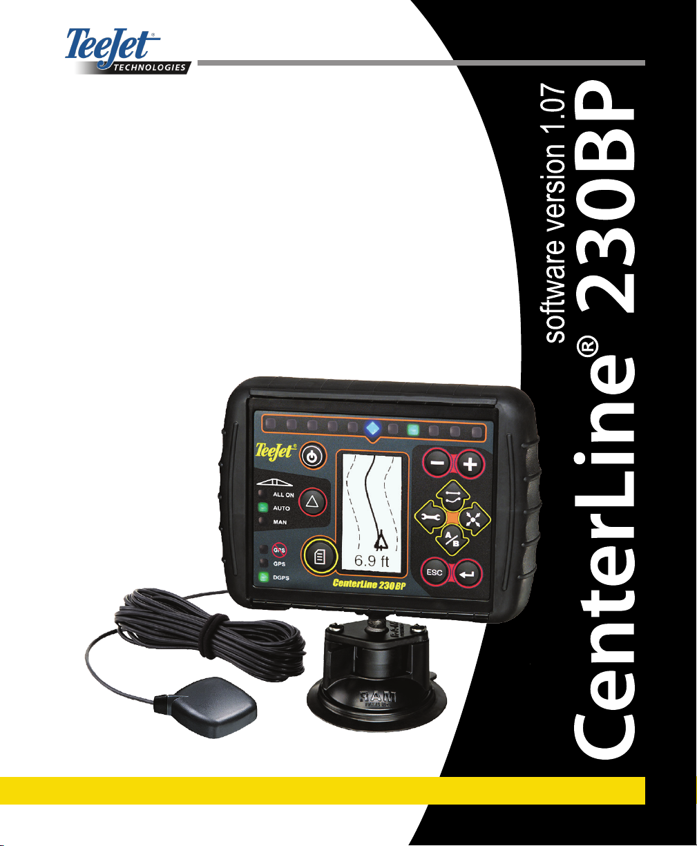
CHAPTER 1 INTRODUCTION
This User Guide provides information for software version
1.07.
The CenterLine 230BP software 1.07 provides the following enhancements to the system:
Applied area now includes only the area under the ac-•
tive boom sections and acre counters will accurately
represent applied area. Prior calculations counted all
area under the entire boom, regardless of whether
individual sections were on or off.
Unapplied area is now considered “untreated” and •
can be treated at a later time.
Boundary area is calculated and displayed as a re-•
sult of a headland perimeter pass in headland circuit
mode. This value is held in memory through the next
power cycle and is erased when the user chooses
to clear the memory and begin application of a new
area.
When a eld boundary is created in headland circuit •
mode, a “No Spray” zone is created outside of that
eld boundary. This boundary and “No Spray” zone is
held in memory through the next power cycle.
Area information and as-applied data are now up-•
dated and saved with greater frequency.
Drive Sensitivity (LED spacing on the lightbar) can •
now be changed in the system Setup menu.
A section width of “0.0” can now be entered.•
Contrast is now adjustable with the +/- keys during •
the startup splash screen. Once GPS is attained, the
+/- revert back to adjustment of screen Brightness.
A system setting for “GPS Source” allowing a devoted •
external source has been added. The default GPS
source is the internal GPS receiver.
DGPS LED activation will now cycle through a 2 min-•
ute delay for the purpose of stabilizing DGPS performance. It is recommended guidance mode operation
begin after the DGPS LED is active.
Tilt Gyro compensation is now available as an up-•
grade to the CL230BP For part numbers and pricing, please consult your regional TeeJet Technologies
representative.
The upgrade includes the support of FieldPilot As-•
sisted Steering. Connection to the SCM is now via
CAN. Existing FieldPilot 220 customers upgrading to
FieldPilot 230 must arrange to exchange their SCM.
Headland Circuit mode has been improved.•
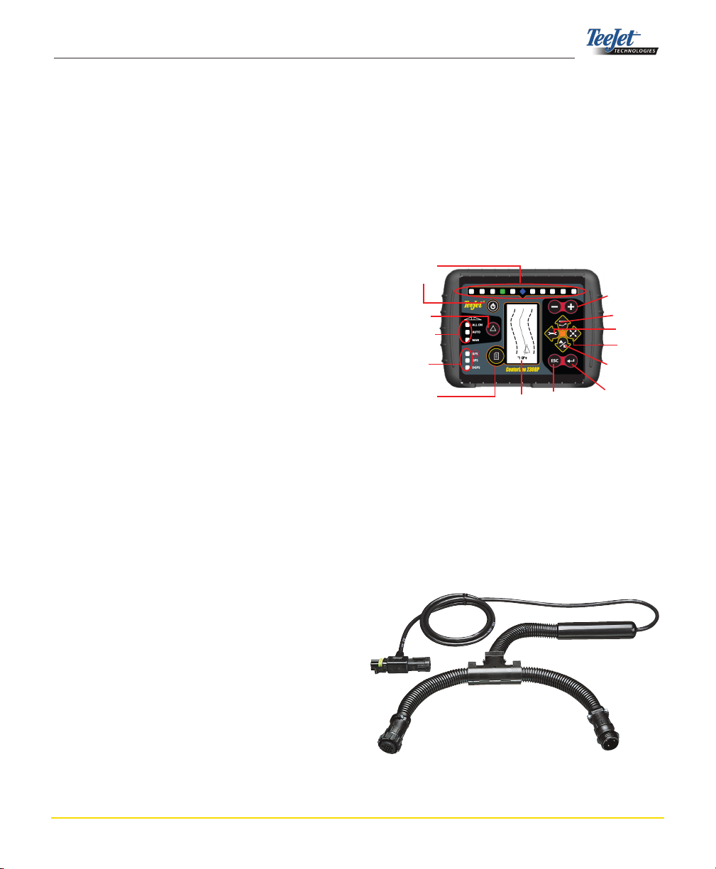
Lightbar
Power
Swath Status
(Selects Mode)
Swath Status Lights
GPS Status Lights
Change Page
Display
Escape
Increase/Decrease
Guidance Mode
Setup Mode
Return to Point
Mark A-B Line
Enter
SMART CABLE - The Smart Cable is the link between
the CL230BP, the existing rate controller, and the boom
section valves. It allows the CL230BP to control the
boom sections automatically.
CenterLine 230BP
98-05112 R4
3
Page 5
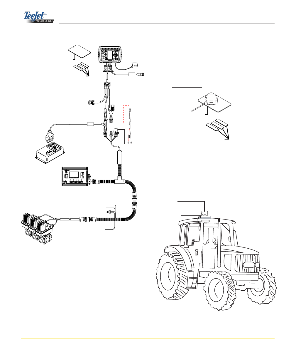
System Conguration
Metal Mounting Plate
65-05179
TM
60-10081 Velcro
External GPS Receiver Input/
Output
GGA 5 Hz
VTG 5 Hz
19200 Baud rate
78-08057
Optional Tilt Gyro Module
TeeJet 844-E
Rate Controller
Valves
RS-232
CAN
TeeJet
CAN
Battery
GPS Antenna
GPS Speed Output
401-0016 Optional
Power Cable
Console
Power
SmartCable
Adapter
Harness
45-05573
Rate
Controller
Harness
Speed Cable
Pow
401-0016
D
C:xx/xx
er
C
a
ble
W
D
A
IRECTL
R
NINGCONN
Y
TOB
A
EC
T.
T
CAUTION
+12VONLY
Remote Swath
Status Switch
(Optional)
Installation - Guidance
Avoid mounting the antenna close to other electrical installations (air conditioning equipment, radio antennas, etc.).
Avoid coiling excess antenna cable - congure it in a “gure 8” shape and keep the cable at least 1.5 feet (45.72
cm) from possible sources of electrical interference.
GPS Antenna
Metal Mounting Plate
65-05179
TM
60-10081 Velcro
Position the GPS antenna in the center of the vehicle at
the highest point with a clear view of the sky. If the tractor
cab is non-metallic, mount the metal plate in the center of
the vehicle at the highest point with the VelcroTM strips and
place the antenna on the plate. Route the antenna cable
carefully to avoid damage and possible electrical interference.
Antenna
Metal plate
Chapter 1 - Introduction4
Page 6
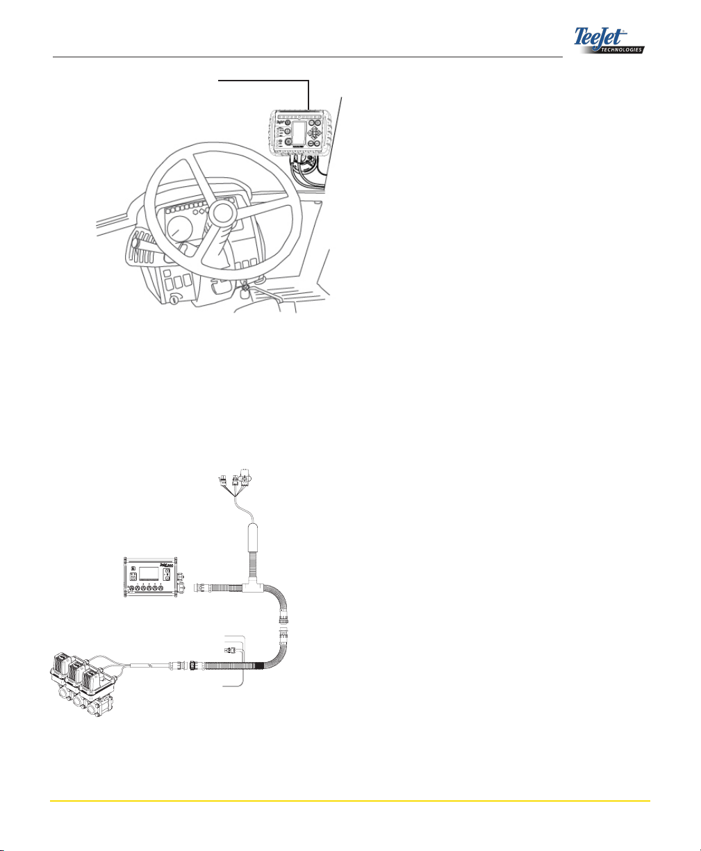
Use the suction cup to mount the console
to the window
Installation - SmartCable
Install the SmartCable between the rate controller and the
harness.
The rate controller Master Switch must be set to the “On”
position and the individual boom section control switches
must be set to the “Off” position.
Valves
TeeJet 844-E
Rate Controller
Master Switch “On”
Boom Section Switches “Off”
Remote Master
RADAR Power
+12 sw
Battery
SmartCable
Adapter Harness
45-05573
Rate Controller Harness
CenterLine 230BP
98-05112 R4
5
Page 7

Chapter 1 - Introduction6
Page 8
CHAPTER 2 SETUP
The CenterLine 230BP is congured to work with Automatic Boom Section Control (ABSC) through the use of
a SmartCable or Section Driver Module (SDM). It is also
congured to work with Assisted Steering through the use
of a Steering Control Module (SCM). A Tilt Gyro Module
is available as a standard feature when a SCM is in use.
It is also able to be used as an add-on feature if no SCM
is present.
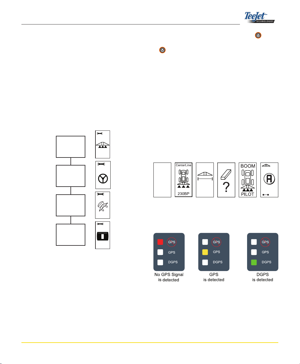
Setup Flow Overview:
Setup
(standard)
Power up the system by pressing the Power button.
Power down the system by pressing and holding the Power button for approximately four (4) seconds. At power
up, the CL230BP will perform the following steps:
Display copyright and software version screen for •
three (3) seconds.
Display the splash screen for two (2) seconds.•
Detect if GPS data are present (this occurs simulta-•
neously within the display screen sequence).
Display the current swath width for three (3) sec-•
onds.
The Area Reset screen will be displayed.•
The splash screen is displayed until the (D)GPS LED •
is illuminated or Setup mode is entered. Once the
console begins receiving (D)GPS positions, the Operation screen will be displayed.
Assisted
Steering
(if present)
Tilt
(if present)
Display
Setup
(standard)
Power Up Sequence
Before starting the CL230BP, make sure the spray controller is powered up, the Master Switch is set to the “On” position, and the individual boom section switches are turned
“Off”.
NOTE: For information regarding the use of
FieldPilot 230, refer to document
# 98-05137 R0.
CL230
BP
V1.07
TeeJet
© 2008
Copyright
Software
Version Screen
Splash
Screen
29.
Swath Width
Screen
+0
5
Area Reset
Screen
Displayed while
waiting for
(D)GPS
6.0 MPH
GPS detected
Operation
Screen
CenterLine 230BP
98-05112 R4
7
Page 9

Area Reset
During the CL230BP power up sequence, the Area Reset
window will be displayed:
Area Reset retains existing bounded and
applied areas and A-B guidelines. This
option allows the bounded and applied
areas and guidelines to be reset before
starting on a new eld or continuing an
existing eld. To reset the bounded and
applied areas and guidelines, press the
Enter key. If the previous application
is being resumed, press the Escape
key to continue to Operation or Setup
mode. This screen is only available upon
CL230BP power up. It cannot be ac-
cessed during normal operation.
Setup Mode
Press the Setup Mode key to enter into CL230BP Setup Mode. The initial CL230BP Setup Mode Screen will be
displayed.
Press the Enter • key to save the setting and ad-
vance the screen.
Press the Escape • key to exit from Setup Mode
without saving any changes.
After 10 seconds of inactivity, Setup Screens will time •
out (changes will be saved). The CL230BP will return
to Operation Mode.
INITIAL SETUP SCREEN
This is the initial CL230BP Setup Screen.
Press the Enter
Delay On screen. Setup screens will
time out after 10 seconds of inactivity
(changes will be saved). After time out,
the screen will go back to Operation
Mode. Press the Escape key to exit
from Setup Mode without saving any
changes.
key to advance to the
NOTE: If a SmartCable or SDM is not connected
to the system, Delay On, Delay Off,
Overlap, Number of Boom Sections, and
Boom Section Width screens will not be
displayed.
DELAY ON
Delay On functions as a “look ahead” for
Setup screens are numbered sequentially
for ease of operation.
timing the boom section valves to switch
on exactly when entering an area that
has not been applied. Delay On time
is established in seconds and tenths of
seconds. If the boom turns on too soon
when entering an un-applied area, decrease the Delay On setting. If the boom
turns on too late when entering an unapplied area, increase the Delay On setting. Use the Plus and Minus keys
to adjust the value. The Delay On Time
range is 0.0 - 10.0 seconds. Press the
Enter key to accept the changes and
advance to the Delay Off setting.
NOTE: To increase the time setting (make On or
Off happen sooner), increase Delay On/
Off respectively. To decrease the time
setting (make On or Off happen later),
decrease Delay On/Off respectively.
Chapter 2 - Setup8
Page 10

DELAY OFF
Delay Off functions as a “look ahead” for
timing the boom section valves to turn
off exactly when entering an area that
has been applied. If the boom turns off
too soon when entering an applied area,
decrease the Delay Off setting. If the
boom turns off too late when entering
an applied area, increase the Delay Off
setting. Delay Off time is established in
seconds and tenths of seconds. Use the
Plus and Minus keys to adjust the
value. The Delay Off Time range is 0.0 -
10.0 seconds. Press the Enter key to
accept the changes and advance to the
Overlap setting.
NUMBER OF BOOM SECTIONS
The number of available boom sections
is 1 to 6 or 1 to 15 depending upon which
SmartCable is detected. Enter the number of boom sections that are active in
the system (1 to 15 sections). Use the
Plus and Minus keys to adjust the
value. Press the Enter key to accept
the changes and advance to the Boom
Section Widths setting.
NOTE: If a SmartCable or SDM is not connected
to the system, one Boom Width can be
entered. The Boom Width entered should
be the total of the entire boom - from 0 to
1969 inches (0 cm to 50 m).
OVERLAP
Overlap determines the amount of over-
lap that is allowed when the boom sections are turned on and off. Select the
percent of overlap from three pre-determined settings (0%, 50%, and 100%)
using the Plus and Minus keys.
Press the Enter key to accept the
changes and advance to the Number of
Boom Sections setting.
BOOM SECTION WIDTHS
Enter the width for EACH boom section
5
in inches (cm). Use the Plus and Minus keys to adjust the value. Press
the Enter key to advance to the next
Boom Section Width setting. When facing forward, the boom sections are ordered from left to right along the boom.
The boom section width range is 0 to
1969 inches (0 cm to 50 m). The minimum recommended width is 39 inches (1
m). Press the Enter key to accept the
changes to the last boom section and advance to the Boom Offset Direction setting. Individual boom section widths can
be set to different widths.
CenterLine 230BP
98-05112 R4
9
Page 11

BOOM OFFSET DIRECTION
A BACKWARD selection (as shown) in-
BOOM OFFSET DISTANCE
Dene the distance from the GPS anten-
Once the nal setting has been entered and saved, the
screen will return to the initial CL230BP Setup Screen. If
no additional changes are required, press the Escape
key to exit to Operation Mode.
6
dicates the boom is located behind the
GPS antenna as the vehicle moves in a
forward direction. A FORWARD selection
indicates the boom is located in front of
the GPS antenna as the vehicle moves
in a forward direction. Use the Plus
and Minus keys to adjust between
Forward or Backward. Press the Enter
key to accept the changes and advance to the Boom Offset Distance setting.
7
na to the boom in decimal feet (decimal
meters). The boom offset distance range
is 0 to 164 decimal feet (0 to 50 decimal
meters). In the example shown, 19.5 feet
equals 19 feet 6 inches. Use the Plus
and Minus keys to change the value.
Press the Enter key to accept the
changes.
Assisted Steering Setup Mode
NOTE: If a Steering Control Module (SCM) is not
connected to the system, Assisted Steering Setup Mode will not be displayed.
Proceed to the next section.
Press the Setup Mode key until the initial Assisted
Steering Setup Mode screen is displayed.
Press the Enter key to save the set-
ting and advance the screen. Press the
Escape key to exit from Setup Mode
without saving any changes. After 10
seconds of inactivity, Setup Screens will
time out (changes will be saved). The
CL230BP will return to Operation Mode.
NOTE: If an SCM is connected to the CL230BP
after it is powered on, the connection will
not be detected. Power must be cycled.
STEERING
Steering allows the Assisted Steer func-
tion to be turned on and off. Use the Plus
or Minus keys to toggle the setting
to “On” or “Off”. Press the Enter key to
accept the changes and advance to the
Look Ahead setting.
v1.00
A checked box activates the Steering
Control system.
v1.00
Chapter 2 - Setup10
Page 12

LOOK AHEAD
Look-ahead
Too High
Look-ahead
Too Low
Look-ahead
Just Right
Increase
Aggressiveness
Decrease
Aggressiveness
Increase
Valve Gain
Decrease
Valve Gain
Decrease
Sensitivity
Increase
Sensitivity
In STRAIGHT mode, ne tune the Look
Ahead by conducting several approaches to the guideline. If the vehicle is overshooting the guideline when approaching, increase the value. If the vehicle
does not overshoot the guideline but instead takes too long to get to the guideline, decrease the Look Ahead value.
Use the Plus or Minus keys to adjust the value
range of 0.0 to 10.0 (default is 4.0 seconds). Press the
Enter key to accept the changes and advance to the
Aggressiveness setting.
AGGRESSIVENESS
Typically, adjust this value while in
CURVED GUIDANCE mode. If the vehicle cuts corners, decrease this value in
increments of one. If the vehicle drives
outside of corners, increase this value.
Use the Plus or Minus keys to increase or decrease the value - range is 1
to 100 (default is 25). Press the Enter
key to accept the changes and advance
to the Valve Gain setting.
VALVE GAIN
If the vehicle is drifting away from the
line or not approaching it fast enough,
increase the Valve Gain setting in increments of one. Decrease the value if the
vehicle is oscillating rapidly or overshooting the guideline. Use the Plus or Minus keys to increase or decrease the
value - range is 1 to 100 (default is 25).
Press the Enter key to accept the
changes and advance to the Sensitivity
setting.
SENSITIVITY
Decrease this value if the steering is too
5
choppy or too responsive. Increase the
value if the vehicle remains consistently
off the guideline. As the value is decreased, stability will increase but so will
a steady state error. Use the Plus or
Minus keys to increase or decrease
the value - range is 0 to 9 (default is 9).
Press the Enter key to accept the
changes and advance to the Valve Test
setting.
CenterLine 230BP
98-05112 R4
11
Page 13

VALVE TEST
Valve Test is used to verify if the steering is directed correctly and to determine the amount of time required to
move the steering wheels from fully left to fully right. Use
the Plus or Minus keys to adjust the left, right, and
off values. The Plus key turns to the right, the Minus
key turns to the left, and pressing either one again will stop
the turn. Press the Enter key to accept the changes and
advance to the Display Setup Mode.
NOTE: If a Tilt Gyro Module is connected but
an SCM is not, the following screen will
be displayed instead of the standard Tilt
Gyro screens. The screen will display the
software version.
Tilt corrected GPS positions provide
improved guidance performance in hilly
terrain. To provide accurate tilt correction, the operator must calibrate the
Steering Control Module (SCM). The
CL230BP will detect if an SCM is connected. If connected, tilt calibration can
be performed.
Once the nal setting has been entered and saved, the
screen will return to the initial CL230BP Assisted Steering
Screen. If no additional changes are required, press the
Escape key to exit to Operation Mode.
WARNING: PINCH POINT HAZARD! To pre-
vent serious injury or death, avoid unsafe
practice while manually operating hydraulic
steering circuits. Keep others away and stay
clear of mechanical steering linkages.
Tilt Gyro Setup Mode
NOTE: If a Steering Control Module (SCM) or a
Tilt Gyro Module are not connected to the
system, Tilt Compensation Setup Mode
will not be displayed. Proceed to the next
section.
Press the Setup Mode
tion Setup Mode screen is displayed.
Press the Enter key to save the set-
ting and advance the screen. Press the
Escape key to exit from Setup Mode
without saving any changes. After 10
seconds of inactivity, Setup Screens will
time out (changes will be saved). The
CL230BP will return to Operation Mode.
TILT GYRO
The Tilt Gyro Module allows for tilt cor-
rection. A Tilt Correction On/Off page
will be displayed. If the page displays
an empty checkbox, the Tilt Calibration
screens will not be available. If the box is
checked, the Tilt Calibration screens will
be accessed. If the box is checked and a
calibration has already been performed,
press the Escape key to avoid performing an additional calibration procedure.
key until the initial Tilt Calibra-
Chapter 2 - Setup12
Page 14

Check/Uncheck the box by using the
Plus
or Minus keys. The Plus
key selects (checks) the box. The Minus
key deselects (unchecks) the box.
Press the Enter key to accept the
changes and advance to the Antenna
Height setting.
ANTENNA HEIGHT
Measure the height of the antenna from
12.5
2
the ground. Enter the antenna height (in
feet and tenths of feet) (meters) on the
antenna height page using the Plus
and Minus keys. Press the Enter
key to accept the changes and advance
to the Level One setting.
FINAL TILT CALIBRATION SCREEN
The Final Tilt Calibration Screen will be
5
displayed. This will show that Tilt Calibration has been completed. After 5 seconds
the screen will time out and return to the
Operation screen.
Display Setup Mode
Press the Setup Mode key until the initial Display Setup
Mode screen appears.
DISPLAY SETUP SCREEN
LEVEL ONE
Position the vehicle on a level surface.
LEVEL TWO
Turn the vehicle 180 degrees and repo-
3
Press the Enter key to advance to the
next Level screen.
4
sition the vehicle at the same location.
Press the Enter key to record the
level position.
This is the initial Display Setup Screen.
Setup screens will time out after 10 seconds of inactivity (changes will be saved).
After time out, the screen will go back to
Operation Mode. Pressing the Escape
key will also exit the user from Setup Mode without saving any changes.
Press the Enter key to advance to the
Display Brightness setting.
DISPLAY BRIGHTNESS
The Plus and Minus keys can be
used to change the brightness levels of
the display screen. Press the keys until
the desired brightness is established.
Press the Enter key to advance to the
Display Contrast setting.
CenterLine 230BP
98-05112 R4
13
Page 15

DISPLAY CONTRAST
The Plus and Minus keys can be
used to change the contrast levels of the
display’s background. Press the Enter
key to advance to the Display Back-
ground setting.
NOTE: The Plus and Minus keys control
console brightness levels during Operations modes. However, if GPS signal is
not being received, the Plus and
Minus keys will control the contrast
level.
DISPLAY BACKGROUND
The Plus and Minus keys toggle
between light and dark backgrounds.
Press the keys until the desired background is established. Press the Enter
key to accept the changes.
COM PORT SETUP
The COM Port can be customized to
send DGPS data out or accept external
DGPS. “0” means the console is accepting external DGPS data. “1” means the
console is using internal DGPS and is
transmitting out. Use the Plus and
Minus keys to toggle the COM Port
number. Press the Enter key to accept the changes.
Power must be cycled to the console if
this setting is changed.
GPS SETUP
GPS Setup can be customized to accept
“ANY” available source transmission (either uncorrected or differential), “GPS”
source transmissions (only uncorrected
ANY
signals), or “DGPS” source transmissions (only differentially corrected signals). Use the Plus key to select
“ANY,” “GPS,” or “DGPS” and the Minus
key to revert backward. Press the Enter key to accept the changes. Power
must be cycled to the console if this setting is changed.
LED SPACING
The distance illustrated by the illuminat-
ed LEDs can be customized. The default
setting is 1.5 feet (.46 meters). Use the
Plus and Minus keys to adjust the
spacing as required for individual preference. Press the Enter key to accept
the changes.
Chapter 2 - Setup14
Once the nal setting has been entered, the screen will
return to the initial Display Setup Mode screen. If no additional changes are required, press the Escape key and
exit to Operation Mode or press the Setup Mode
again to enter into CL230BP Setup Mode.
key
Page 16

CHAPTER 3 OPERATION
The CenterLine 230BP is congured to work with Automatic Boom Section Control (ABSC) through the use of
a SmartCable or Section Driver Module (SDM). It is also
congured to work with Assisted Steering through the use
of a Steering Control Module (SCM). A Tilt Gyro Module
is available as a standard feature when a SCM is in use.
It is also able to be used as an add-on feature if no SCM
is present.
Power Up Sequence
Power up the system by pressing the Power button.
Power down the system by pressing and holding the Power button approximately four (4) seconds.
CL230
BP
V1.07
TeeJet
© 2008
Copyright
Software
Version Screen
Splash
Screen
29.
Swath Width
Screen
+0
5
Area Reset
Screen
Displayed while
waiting for
(D)GPS
6.0 MPH
GPS detected
Operation
Screen
At power up, the CenterLine 230BP will perform the following steps:
Display copyright and software version screen for •
three (3) seconds.
Display the splash screen for two (2) seconds.•
Detect if GPS data are present (this occurs simulta-•
neously within the display screen sequence).
Display the current swath width for three (3) sec-•
onds.
The Area Reset screen will be displayed.•
The splash screen is displayed until the (D)GPS LED •
is illuminated or Setup mode is entered. Once (D)GPS
is locked, the Operation screen will be displayed.
CenterLine 230BP Operation
Reference Screens
Navigation Screen - Mark A-B
+0
Guidance Mode
Straight A-B Guidance
Curved A-B Guidance
Circle Pivot Guidance
Headland Circuit
Swath Number
+ to the right of the A-B baseline
- to the left of the A-B baseline
Action Indicator (currently
Mark Point A)
Vehicle Speed
Return to Point Indicator
indicates a point is stored
CenterLine 230BP
98-05112 R4
15
Page 17

Navigation Screen - Operation
This icon located in the
upper left corner of the
screen indicates that
Assisted Steering is engaged.
Direction to main guideline
Guidance Mode
Straight A-B Guidance
Curved A-B Guidance
Circle Pivot Guidance
Headland Circuit
+1
1.5
Guidance Screen - Map Page
This icon located in the
upper left corner of the
screen indicates that
Assisted Steering is engaged.
Next guideline to the left
6.0 Ft
Swath Number
+ to the right of the A-B baseline
- to the left of the A-B baseline
Distance to main guideline
Vehicle Speed
Center guideline
Next guideline to the right
Distance from
center guideline
Bounded Area Screen
NOTE: If a SmartCable is not connected to the sys-
tem, the console cannot be placed in “Auto”
mode. However, acreage can be bounded.
Bounded Area
Indicates a bounded area has been completed
1435.00
Acres (Hectares) Bounded
Indicates the number of hectares (acres) bounded
by Headland
Circuit
Applied Area Screen
NOTE: This screen will not be displayed if a Smart-
Cable or SDM is not installed in the system.
Applied Area 1
The highlighted area indicates
which Applied Area is selected
for reset.
1
1200.0
May be used to display the accumulated total
of applied area (in acres/hectares) of the CUR-
RENT eld (user preference).
Auto Boom Section Control Screen
NOTE: This screen will not be displayed if a Smart-
Cable or SDM is not installed in the system.
Mode Indicator
ALL - All On mode overrides
the controller boom section
status and turns all boom
sections on. The Swath Sta-
tus key must be held the
entire duration of operating
in ALL ON mode.
AUTO - Auto mode allows
the CenterLine 230BP to automatically control the boom
sections.
MAN - Manual mode dis-
ables automatic boom section control. The operator
controls the boom sections
via the rate controller boom
switches.
Chapter 3 - Operation16
AUTO
6.0
MPH
Vehicle Speed
Individual Boom Section Status
The CenterLine 230BP can control up
to 15 boom sections. Hollow triangles
indicate the boom section is “off”. Solid
triangles indicate the section is “on”.
Example:
Boom
Section
Off
Boom
Section
On
2
Applied Area 2
May be used to display the accumu-
lated total area of all elds applied
(user preference).
33200.0
Acres
To reset an existing area counter, while on the Applied
Area Screen, press the Enter key to highlight Applied
Area 1. Press and hold the Minus key for approximately
3 seconds to reset the total in Applied Area 1. If the area
counter was reset by mistake, press the Plus key again
to restore the existing total.
Highlight Applied Area 2 by pressing the Enter key.
Press and hold the Minus key for approximately 3 seconds to reset the total in Applied Area 2. If the area counter was reset by mistake, press the Plus key again to
restore the existing total. Pressing the Escape key will
deselect the highlighted area.
Page 18

NOTE: Once the Applied Area Screen is exited,
the area reset will become permanent. The
restore feature cannot be used after the
screen has been exited.
To exit the Applied Area screen, select the Change Page
key. The CenterLine 230BP will advance to the Navi-
gation screen.
Operations Screens
Several screens are displayed during vehicle operation.
They are consistent throughout the application and appear
as follows.
To change the view of any screen during Operations mode,
press the Change Page
key.
NOTE: If the system is not connected to a Smart-
Cable, Applied Area will not be accumulated. The Applied Area screen will not be
displayed.
Operation Function Keys
There are several functions that can be performed during
operation. Most of these functions are initiated by the four
arrow keys, located on the keypad.
Guidance Mode
Setup Mode
This key exits OPERATION and
enters SETUP mode.
Mark A-B Line
This key allows the operator to establish a
new A-B line.
NOTE: The Plus and Minus keys control
console brightness levels during Operations modes. However, if GPS is not being
received, the Plus and Minus keys
will control the contrast level.
This key selects the desired guidance mode:
Straight A-B Guidance
Curved A-B Guidance
Circle Pivot Guidance
Headland Circuit
Return to Point
This key allows the operator to establish a
point in memory so CenterLine 230BP can
navigate the vehicle back to that point.
+2
1.5
6.0 MPH
Navigation
Screen
6.0 Ft
Map Page
AUTO
6.0
MPH
Auto Boom Screen
Completed Circuit -
Calculated Area
1
1200.0
2
33200.0
Acres
Applied Area
Screen
Guidance Operation - Modes
Guidance capabilities include Straight A-B, Curved A-B,
Circle Pivot, and Headland Circuit.
7.5 ft (2.3 m)
4.5 ft (1.4 m)
6.0 ft (1.8 m)
lights illuminated on the right of the
lightbar require a steering adjustment
to the left
lights illuminated on the left of the
lightbar require a steering adjustment
to the right
1.5 ft (.45 m)
Center
3.0 ft (.9 m)
NOTE: LED spacing can be customized for user
preference. Refer to page 14 for information on adjusting LED spacing.
CenterLine 230BP
98-05112 R4
17
Page 19

Headland Circuit Guidance
Headland Circuit guidance is used to establish a perimeter
around the application area. The CenterLine 230BP will
collect and store bounded area once the Headland Circuit
is closed. The CenterLine 230BP will allow two passes
around the perimeter of the eld - the original perimeter
pass and one additional pass. Guidance is applied during
the second pass, after the rst pass has been completed.
NOTE: Booms will not operate outside of the
bounded area once it is established.
5. Drive to the desired headland location of Point A. With
the vehicle in motion, press the Mark A-B
key to
establish Point A. Drive around the perimeter of the
eld. The CenterLine 230BP will automatically close
the boundary when the vehicle is within one boom
width of Point A. The Completed Circuit (hourglass)
will be briey displayed as the perimeter is closed.
Guidance Points A and B can be established at any
time during Headland Circuit mode. These points can
be used as reference for Straight or Curved A-B guidance (used during interior application). To mark Points
A and B, press the Guidance Mode
key to select
either Straight, or Curved A-B mode and mark the
points at the desired locations using the Mark A-B
key. The points will be stored for future reference.
NOTE: Steps 1 - 3 are not applicable if a SmartCa-
ble or SDM is not installed on the system.
1. Turn the controller master switch to the “On” position.
The individual boom section switches should remain
in the “Off” position.
2. To activate automatic boom section control, press the
Swath Status Switch key until Auto Mode is illuminated on the console.
ALL ON
AUTO
MAN
3. In areas where application is not desired, manually
turn “Off” the rate controller master switch to shut off
the booms. Turn the master switch “On” to resume
application.
4. Use the Guidance Mode
key to select Headland
Circuit guidance.
Return to Headland Circuit view by pressing the Guid-
ance Mode
key until the Headland Circuit Mode
screen is once again displayed.
The CenterLine 230BP will provide navigation infor-
mation to complete a second headland circuit pass.
If Guidance Points A and B were not marked during
Headland Circuit, select a new Guidance Mode and
establish an A-B line to complete the interior application.
6. Use the Change Page key to advance the screen
views as illustrated on page 17.
Straight A-B Guidance
Straight A-B guidance provides straight line guidance
based on a reference (A-B) line. The original A-B line is
used to calculate all other parallel guidelines.
B
A
Chapter 3 - Operation18
Page 20

NOTE: Steps 1 - 3 are not applicable if a SmartCa-
ble or SDM is not installed on the system.
1. Turn the controller master switch to the “On” position.
The individual boom section switches should remain
in the “Off” position.
Curved A-B Guidance
Curved A-B Guidance is similar to Straight A-B Guidance
except that the reference line is curved.
B
2. To activate automatic boom section control, press the
Swath Status Switch key until Auto Mode is illuminated on the console.
ALL ON
AUTO
MAN
3. In areas where application is not desired, manually
turn “Off” the rate controller master switch to shut off
the booms. Turn the master switch “On” to resume
application.
4. Use the Guidance Mode
key to select Straight
A-B guidance.
5. Drive to the desired location of Point A. While the
vehicle is in motion, press the Mark A-B
key to
establish Point A. Point B will be displayed on the
screen. Drive to the location of Point B and press
the Mark A-B
key again to establish the A-B line.
The CenterLine 230BP will immediately begin providing navigation information with the lightbar and
Navigation Screen.
+0
+0
+0
0.0
A
NOTE: Curved Guidance is recommended not to
exceed 300 within the A-B guideline.
NOTE: Steps 1 - 3 are not applicable if a SmartCa-
ble or SDM is not installed on the system.
1. Turn the controller master switch to the “On” position.
The individual boom section switches should remain
in the “Off” position.
2. To activate automatic boom section control, press the
Swath Status Switch key until Auto Mode is illuminated on the console.
ALL ON
AUTO
MAN
3. In areas where application is not desired, manually
turn “Off” the rate controller master switch to shut off
the booms. Turn the master switch “On” to resume
application.
4. Use the Guidance Mode
key to select Curved A-B
guidance.
Establish
Point A
Establish
Point B
Navigation
Screen
6. Use the Change Page key to advance the screen
views.
5. Drive to the desired location of Point A. While the
vehicle is in motion, press the Mark A-B
key to
establish Point A. Point B will be displayed on the
screen. Drive to the location of Point B and press the
Mark A-B
key again to establish the A-B line. The
CenterLine 230BP will begin providing navigation information with the lightbar and Navigation Screen.
CenterLine 230BP
98-05112 R4
19
Page 21

6. Use the Change Page
views.
Establish
Point A
+0
Establish
Point B
+0
0.0
Navigation
Screen
key to advance the screen
+0
5. Drive to the desired location of Point A. With the vehicle in motion, press the Mark A-B
key to establish
Point A. Point B will be displayed on the screen. Drive
to the location of Point B and press the Mark A-B
key again to establish the A-B line. Point B must be
at least 1/2 of the way around the circle to complete
the circle pivot. Once Point B has been established,
the CenterLine 230BP will begin providing navigation
information with the lightbar and Navigation Screens.
+0
+0
+0
Circle Pivot Guidance
Circle Pivot guidance provides guidance around a central
location that radiates outward.
A
B
NOTE: Steps 1 - 3 are not applicable if a SmartCa-
ble or SDM is not installed on the system.
1. Turn the controller master switch to the “On” position.
The individual boom section switches should remain
in the “Off” position.
2. To activate automatic boom section control, press the
Swath Status Switch key until Auto Mode is illuminated on the console.
ALL ON
AUTO
MAN
3. In areas where application is not desired, manually
turn “Off” the rate controller master switch to shut off
the booms. Turn the master switch “On” to resume
application.
Establish
Point A
Establish
Point B
6. Use the Change Page
0.0
Navigation
Screen
key to advance the screen
views.
Compass View/Return to Point
Press the Return to Point key to establish a point in memory. Normal guidance will continue uninterrupted during
this process.
To navigate back to the established
6.0 MPH
point, press the Return to Point
again. The Compass View screen will
be displayed and will provide navigation
assistance to return to the established
point.
Push the Return to Point
time to erase the stored point and return
to the navigation screens.
key
key a third
4. Use the Guidance Mode
guidance.
Chapter 3 - Operation20
key to select Circle Pivot
Page 22

All Booms On Mode
The CenterLine 230BP provides the option of turning all
booms on at the same time, regardless of vehicle position
or guidance mode. To turn all booms on, while the vehicle
is moving, press and hold the Swath Status Switch key
until All On Mode is illuminated on the console. Release
the Swath Status Switch key to turn off the booms.
ALL ON
AUTO
MAN
A+ Nudge Feature
The A+ Nudge feature allows the existing A-B guideline to
be shifted to the vehicle’s current location. Press the Mark
key immediately followed by pressing the Plus
A-B
key.
Pressing the Minus key after pressing the Plus key
will abort the nudge feature and the guideline will remain
the same.
CenterLine 230BP
98-05112 R4
21
Page 23

Chapter 3 - Operation22
Page 24

CenterLine 230BP
98-05112 R4
23
Page 25

Chapter 3 - Operation24
Page 26

1801 Business Park Drive
Springeld, Illinois 62703 USA
(217) 753-8424
www.teejet.com
 Loading...