

Page 1
CenterLine
U s e r G u i d e
98-05054
Page 2

Page 3

CenterLine
Software Version 2.00
CenterLine v2.00 Table of Contents
Introduction........................................................................................................................2
About CenterLine ..........................................................................................................2
Straight or Curved Guidance ...................................................................................2
Wireless Remote Control Unit.................................................................................2
Lightbar Shows you the Information You Want .....................................................2
What’s new in Version 2.00 ....................................................................................3
Menu Items and Pick List Text ...............................................................................4
Menu Items Next and To Start.................................................................................5
Software Components..............................................................................................5
Wireless Remote Control.........................................................................................6
General Operation....................................................................................................6
FCC Statement.........................................................................................................6
CenterLine Lightbar.................................................................................................7
Lightbar Specifications ............................................................................................7
CenterLine Quick Start-up ...............................................................................................8
General Start-up Sequence.............................................................................................8
First Time Start-up Sequence ........................................................................................8
CenterLine Product Kits ...................................................................................................9
CenterLine Kit without DGPS Receiver........................................................................9
CenterLine Kit with RX 360p WAAS DGPS Receiver ..............................................10
CenterLine Kit with RX 350p WAAS DGPS Receiver ..............................................11
CenterLine with RX 400p DGPS Receiver .................................................................12
CenterLine Setup .............................................................................................................13
Guidance Setup ............................................................................................................14
Swath Manager 5 ..................................................................................................15
% Overlap ............................................................................................................. 16
Sections..................................................................................................................16
Width 1-5 ...............................................................................................................16
Delay .....................................................................................................................17
Entering Applied Zone ..........................................................................................17
Exiting Applied Zone ............................................................................................17
Width ....................................................................................................................18
Ahead .....................................................................................................................18
Antenna .................................................................................................................19
Direction ................................................................................................................19
Distance .................................................................................................................20
Height.....................................................................................................................20
Status......................................................................................................................21
Alarm .................................................................................................................... 22
GPS Type...............................................................................................................23
CenterLine v2.00 Table of Contents
1
Page 4

CenterLine
Software Version 2.00
1 Hz Msg................................................................................................................24
Lightbar Setup..............................................................................................................25
Spacing...................................................................................................................25
Mode ......................................................................................................................26
Text 1 and Text 2 ...................................................................................................26
Text 1 27
Text 2 .....................................................................................................................28
Steer Bar ................................................................................................................29
System Setup................................................................................................................30
Units.......................................................................................................................30
Language................................................................................................................31
CenterLine Setup Flow Diagram....................................................................................32
Tools ..................................................................................................................................33
Receiver .......................................................................................................................34
Lightbar........................................................................................................................34
e-Dif .............................................................................................................................34
e-Dif Info .....................................................................................................................35
Demo............................................................................................................................35
Next..............................................................................................................................35
To Start ........................................................................................................................35
CenterLine Real-Time Operation ..................................................................................36
Starting Real-time Operation .......................................................................................36
New? Resume? ......................................................................................................36
Real-time Operation.....................................................................................................37
Real-time Menu .....................................................................................................37
Apply On/Off.........................................................................................................37
Marking A and B Locations...................................................................................38
Switching between Guidance Modes.....................................................................38
A+ Feature .............................................................................................................39
Area Determination................................................................................................39
Return to Point .......................................................................................................40
Exiting Real-time Operation ..................................................................................40
Headland Guidance Operation.....................................................................................41
Reference Guideline ..............................................................................................41
Headland Pattern Example.....................................................................................41
Switching from Headland to Straight-line Mode...................................................43
Headland Mode Lightbar Graphics........................................................................45
Straight-line Guidance Operation ................................................................................47
Curve AB Guidance Operation....................................................................................49
Applied Area Detection ...............................................................................................51
Detecting A Previously Applied Area ...................................................................51
Detecting Neighboring Swath................................................................................52
Lightbar Index .................................................................................................................53
2
CenterLine v2.00 Table of Contents
Page 5

CenterLine
Software Version 2.00
Swath Manager 5 Operation...........................................................................................57
Starting Swath Manager 5............................................................................................57
Installation .............................................................................................................57
Swath Manager 5 Auto Boom Engage: ................................................................58
Swath Manager 5 Auto Boom Disengage..............................................................58
CenterLine v2.00 Table of Contents
3
Page 6

CenterLine
Software Version 2.00
4
CenterLine v2.00 Table of Contents
Page 7
CenterLine
A lightbar guidance system with wireless remote control.
Software Version 2.00
CenterLine
MENU
ESC
CenterLine
CenterLine
UP
DOWN
CenterLine
Midwest Technologies IL, LLC
CenterLine
Page 8

CenterLine
Software Version 2.00
Introduction
About CenterLine
CenterLine is a low-cost lightbar guidance system, controlled by a wireless remote. CenterLine
provides accurate straight-line and cur ved gu ida nce, for use in spraying, seeding, and other
related jobs at a cost that rivals foam markers. The CenterLine product comes with a combination
Beacon/WAAS or W AAS only DGPS receiver, providing sub-meter, p ass to pass, positioning accuracy. The wireless remote control is used to set-up and operate the system through menus and
options displayed on the lightbar.
CenterLine’s attractive design combines a compact size with easy to see LEDs that are fully
adjustable. Using dedicated buttons on the wireless r emote, the lightbar can be dimmed to efficiently run at night and brightened to be easily seen in full sunlight.
Straight or Curved Guidance
CenterLine guides along swaths of all kinds with sub-meter, pass to pass, accuracy. Select the
driving pattern and CenterLine determines the closest swath to follow. There’s no need to decide a
guidance pattern ahead of time, or to commit to a pattern for the entire job. Centerline allows the
switching of patterns in real-time, determining when a new pattern is being used and keeping the
operator informed of the current status.
Wireless Remote Control Unit
CenterLine’s ergonomic, handheld, remote control is easier to use than most TV remotes. Seven
easy to read keys allow the scrolling of menus displayed on the lightbar. The remote keypad is
backlit for night-time operation, and 3 AAA batteries (included) powers the unit for an entire season.
The small, powerful, remote permits mounting the weather-resistant lightbar outside on the hood
or in the cab. When mounted outside, wireless communication permits easy operation while the
cab stays clean and sealed from dust and contaminants.
Lightbar Shows you the Information You Want
A text display on the lightbar reports a choice of gu idance in fo rma tion. It also wa rns wh en an area
of the field is entered that has already been applied. Guidance text information can be turned off, if
preferred. Choose two of these guidance messages to monitor progress in real-time:
• Cross-Track Error,
• Current Swath Number,
• Vehicle Speed,
• Applied Area,
• Vehicle course on the ground.
2 CenterLine
Introduction
Page 9

CenterLine
Software Version 2.00
What’s new in Version 2.00
• “A +” feature to Straight and Curved AB guidance modes.
• Swath Manager 5 support
• Larger Christmas tree for Headland and Curved AB guidance.
• Spanish, Italian, French, Portuguese, German, Dutch, and Danish ha ve been updated to
include Swath Manager 5
CenterLine 3
Introduction
Page 10
CenterLine
Software Version 2.00
Menu Items and Pick List Text
Throughout this user’s guide, menu item text is displayed between the <> characters, For example, <START>. Keys on the remote (See Figure 4 on page 6) are denoted in bold italics, such as
Enter.
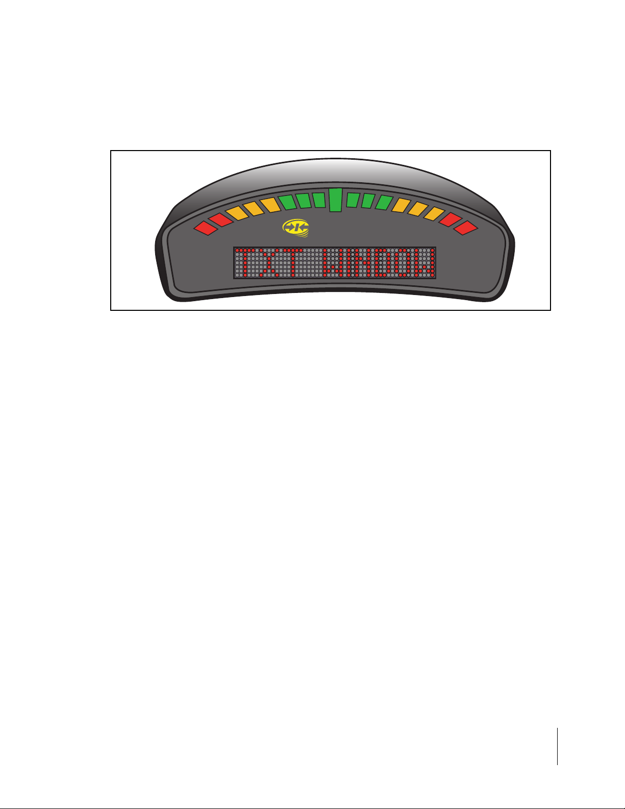
Most of the figures in this user’s guide are of menu items that are displayed in the text window of
the lightbar (See Figure 5 on page 7). This text represents either a menu item, such as <GUIDANCE> or a pick-list item, such as <METRIC>. The lightbar text window can display a single line
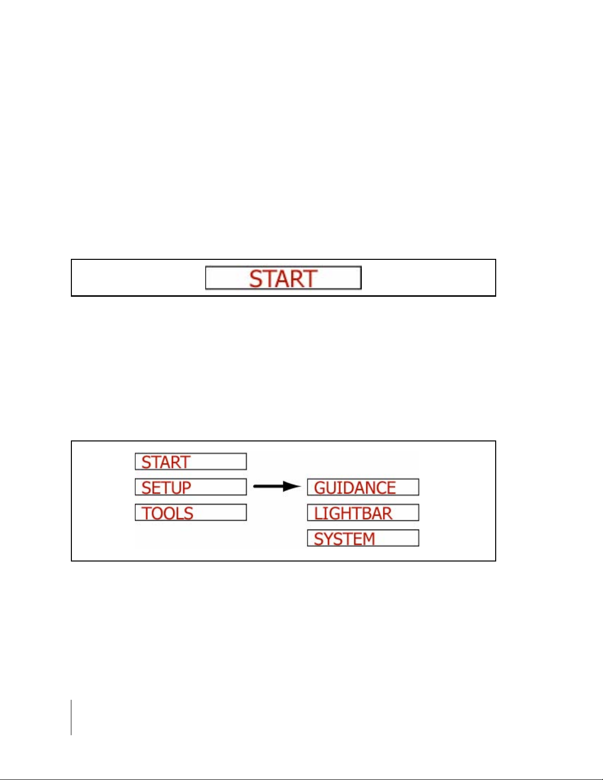
of text up to ten characters long. Figure 1 shows an example of a single text line that would be di splayed on the lightbar.
Figure 1: Example of Text Displayed on Lightbar
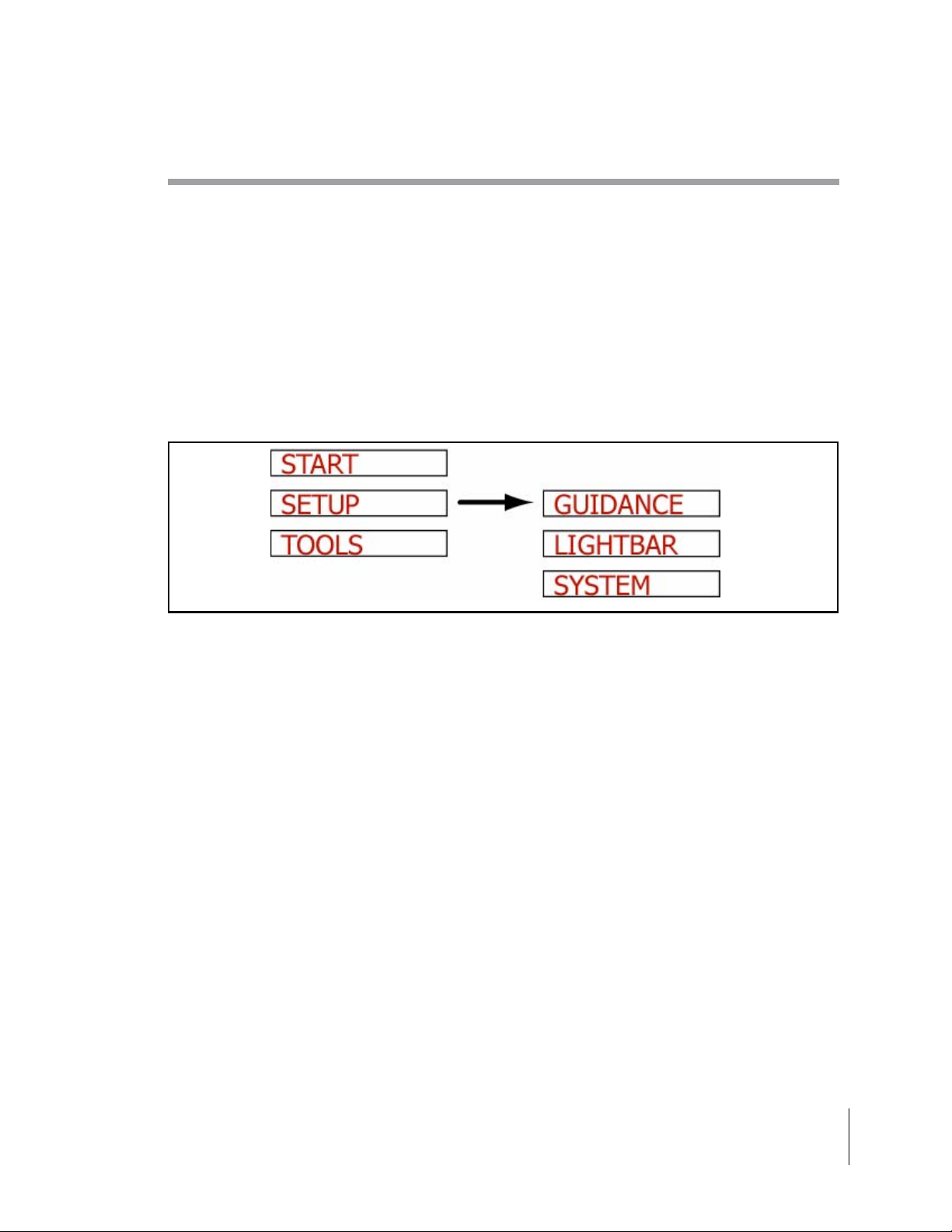
Figures with multiple menu items are depicting the menu items that are above, below, left, and
right of the text line currently in view. Figure 2 shows several menu items. The current menu item
in view is <SETUP> and is denoted with a black arrow to the right side of the text. This figure is
showing that the Up and Down arrow keys can be used to scroll between <START>, <SETUP>,
and <TOOLS>. If the Enter key on the remot e is pres sed, t he displ ay move s to the <GUIDA NCE>
setup menu item. This figure also shows that, from the <GUIDANCE> menu item, it is possible to
scroll between the <GUIDANCE>, <LIGHTBAR>, and <SYSTEM> setup menus using the Up and
Down arrow keys.
Figure 2: Displaying Multiple Text Lines
4 CenterLine
Introduction
Page 11
CenterLine
Software Version 2.00
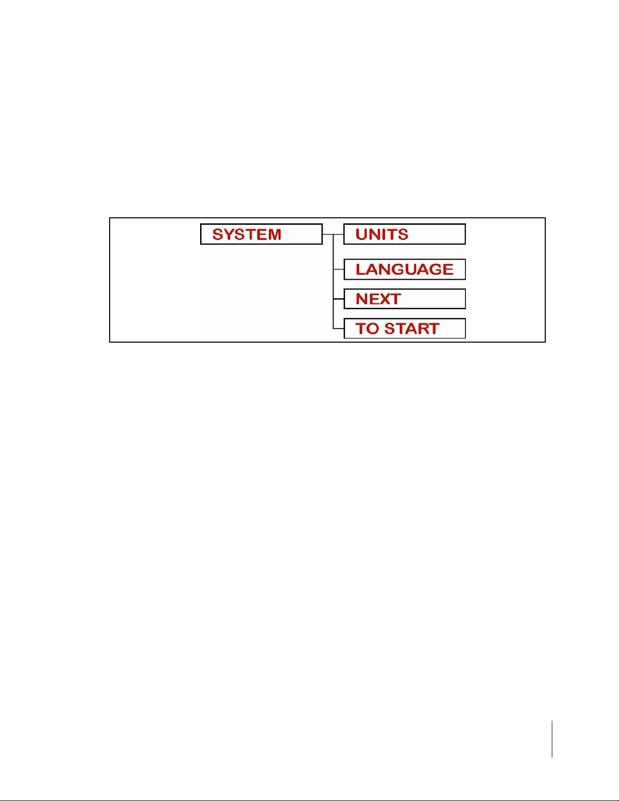
Menu Items Next and To Start
There are two additional menu items that are found in almost every menu; <NEXT> and <TO
START>. Figure 3 shows the <NEXT> and <TO START> menu items in the System Setup menu
list. Pressing Enter at <NEXT> brings up the next menu heading. As an example, pressing Enter
at <NEXT>, while in Lightbar setup, brings up <SYSTEM>. In the same example, pressing ESC at
<NEXT> brings up the <LIGHTBAR> menu Item. Selecting <TO START> automatically goes back
to the <ST ART> menu. From here real-time guid ance can be started. Using <T O START> is useful
when it is necessary to quickly change one setting and then go right back into real-time operation.
Figure 3: Next and To Start Menu Items
Software Components
CenterLine software can be broken into three components: Setup (See “CenterLine Setup” on
page 13), Real-Time (See “CenterLine Real-Time Operation” on page 36), and Tools (See “Tools”
on page 33). Setup allows the configuring of the Cente rLine to best suit the current needs, and th e
Real-Time component handles all of the real-time guidance operations. The Tools component provides basic diagnostics for the lightbar and the attached GPS receiver.
CenterLine 5
Introduction
Page 12
CenterLine
Software Version 2.00
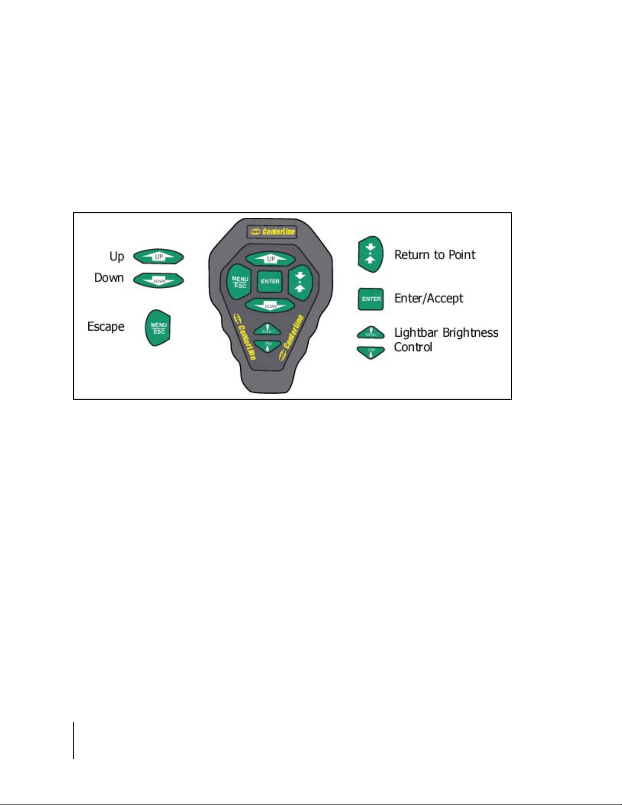
Wireless Remote Control
General Operation
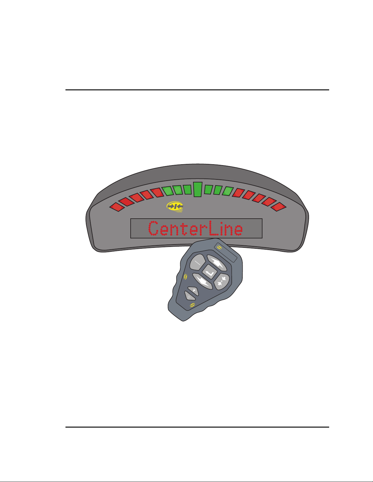
Operation of CenterLine software is via remote ke ypad input and menu items displayed in the text
display area (See Figure 5) of the CenterLine lightbar. The Up and Down arrow keys are used to
scroll through menus, sub-menus, and pick lists. The Enter key is used to enter menus and submenus, and accept a desired pick-list entry. The ESC key acts as cancel.
Figure 4: The Wireless Remote Control Unit
FCC Statement
This device complies with part 15 of the FCC Rules. Operation is subject to the following two conditions: (1) This device may not cause harmful interference, and (2) this device must accept any
interference received, including interference that may cause undesired operation.
QS7CL7850094
QS7CL7850107
TR19JN96.008
Changes or modifications to the product, not expressly approve d by Midwest Technologies Illinois,
LLC, could void the user's authority, as granted under Part 15 of the FCC Rules, to operate the
equipment.
6 CenterLine
Introduction
Page 13
CenterLine
Software Version 2.00
CenterLine Lightbar
TM
CenterLine
Figure 5: The CenterLine Lightbar
Lightbar Specifications
Housing Material: ABS/Poly carbonate alloy construction.
Dimensions: 3.70”H x 9.40”W x 3.80”D (95 mm x 240 mm x 100 mm)
Weight: 0.8 lbs (0.36 kg)
Processor: Intel StrongARM
MEMORY: 16 MB Ram, 2 MB Flash
LEDs: High-lumen red, yellow, and green radial light pattern and 10 character
LED alpha-numeric text display. Full brightness control adjustment using
wireless remote.
Operating Voltage: 10-14 VDC
Operating Temp: 32 to 160 F (0 to 70 C)
Storage Temp: -40 to 185 F (-40 to 85 C)
I/O to DGPS: 1 asynchronous RS 232
I/O to Control Unit: Wireless link operating at 433 MHz. FCC part 15 and Industry Canada
RSS-210 certified. Other certifications pending.
Mounting: Mounting bracket supplied. Magnetic and suction mounts are optional.
CenterLine 7
Introduction
Page 14

CenterLine
Software Version 2.00
CenterLine Quick Start-up
The following section assumes that your CenterLine hardware has been properly set up. See
“CenterLine Product Kits” on page 9 - 12 for information on how to configure the system.
General Start-up Sequence
• Apply power to CenterLine.
• Lightbar performs a start-up sequence.
• Lightbar displays current software version.
• Lightbar displays <START>.
• <START> display should remain until Enter is pressed to start real-time guidance or the Start
menu is scrolled, using Up or Down to move to another menu option; <SETUP> or <TOOLS>.
First Time Start-up Sequence
• Apply power to CenterLine.
• Lightbar performs a start-up sequence.
• Lightbar displays current software version.
• Lightbar displays <START>.
• Using Up or Down, scroll until <SETUP> is displayed on the lightbar. Press Enter.
• Set up the CenterLine system by choosing the proper selections found in the three setup submenus <GUIDANCE>, <LIGHTBAR>, and <SYSTEM>. It is important to have the correct
swath width entered.
• Return to the <START> location and press Enter to begin real- time guidance.
8 CenterLine
CenterLine Quick Start-up
Page 15
CenterLine
Software Version 2.00
CenterLine Product Kits
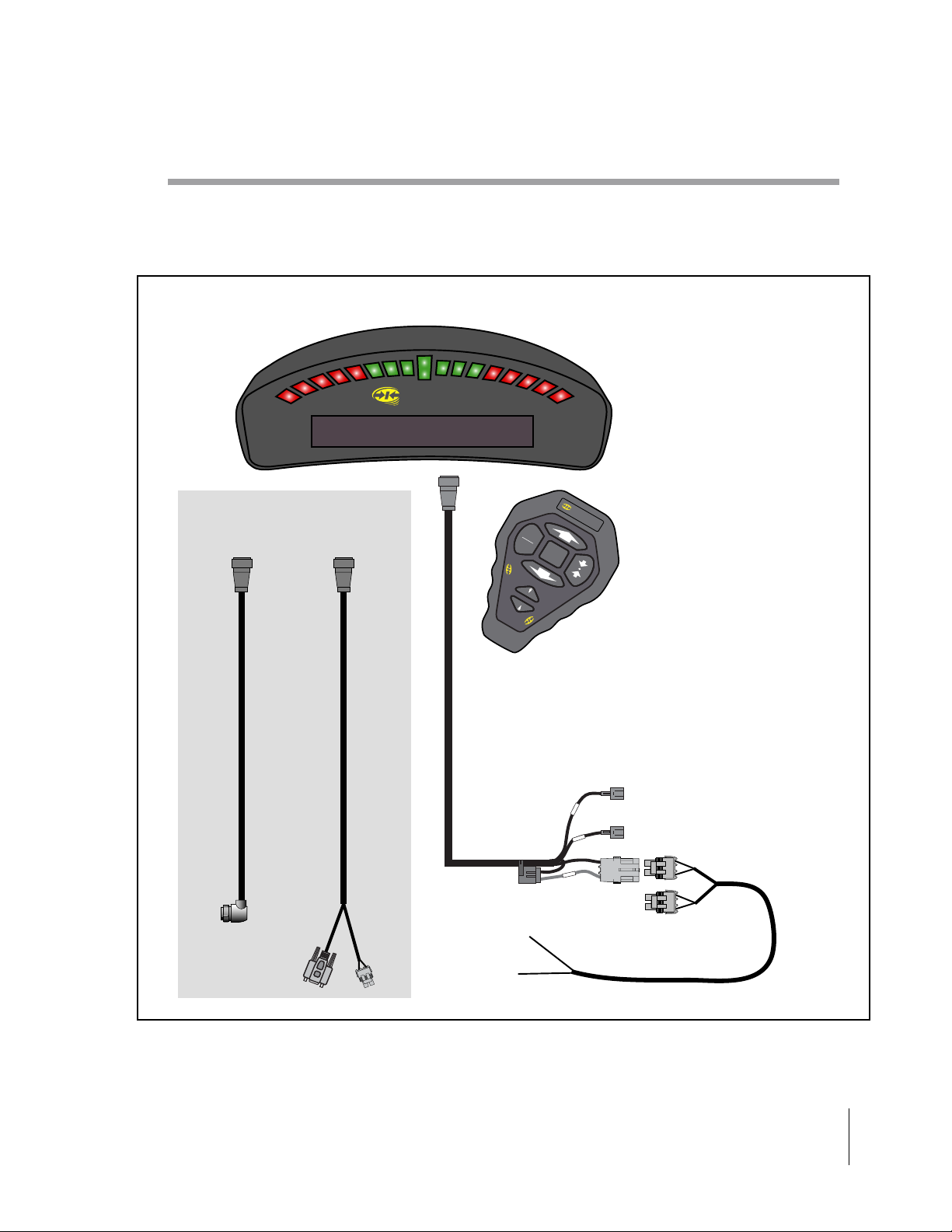
CenterLine Kit without DGPS Receiver
CenterLine Lightbar
CenterLine
A GPS data cable is
required but not provided in kit.
M
EN
U
ESC
DOWN
CenterLine
BRIGHT
DIM
CenterLine
CenterLine
Power Cable
12'
5 Amp
To
Battery
CenterLine
UP
CenterLine
Wireless Remote
Boom Sense -
e
ns
e
S
Acc
t
a
B
+12V when booms are ON
Ignition Sense -
+12V when ignition is ON
Power Cable
12'
Figure 6: CenterLine without DGPS Receiver
CenterLine 9
CenterLine Product Kits
Page 16
CenterLine
Software Version 2.00
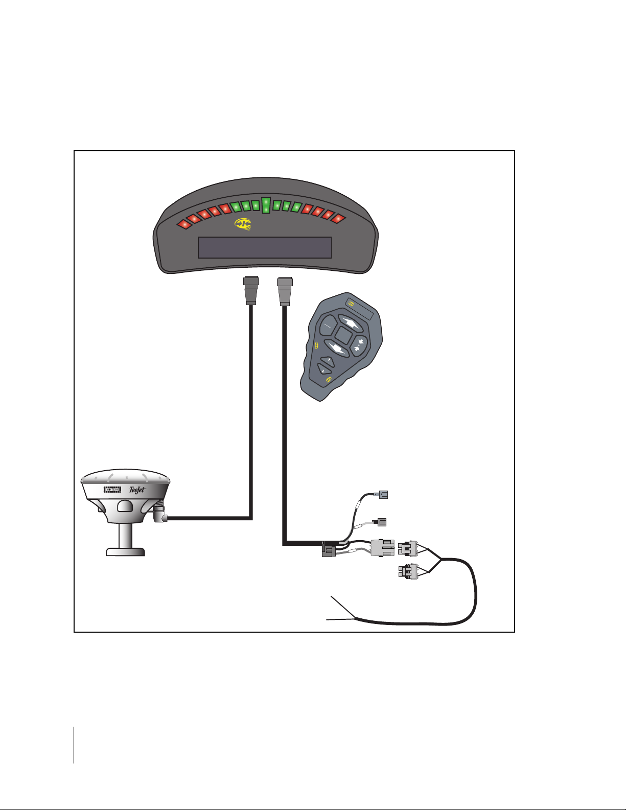
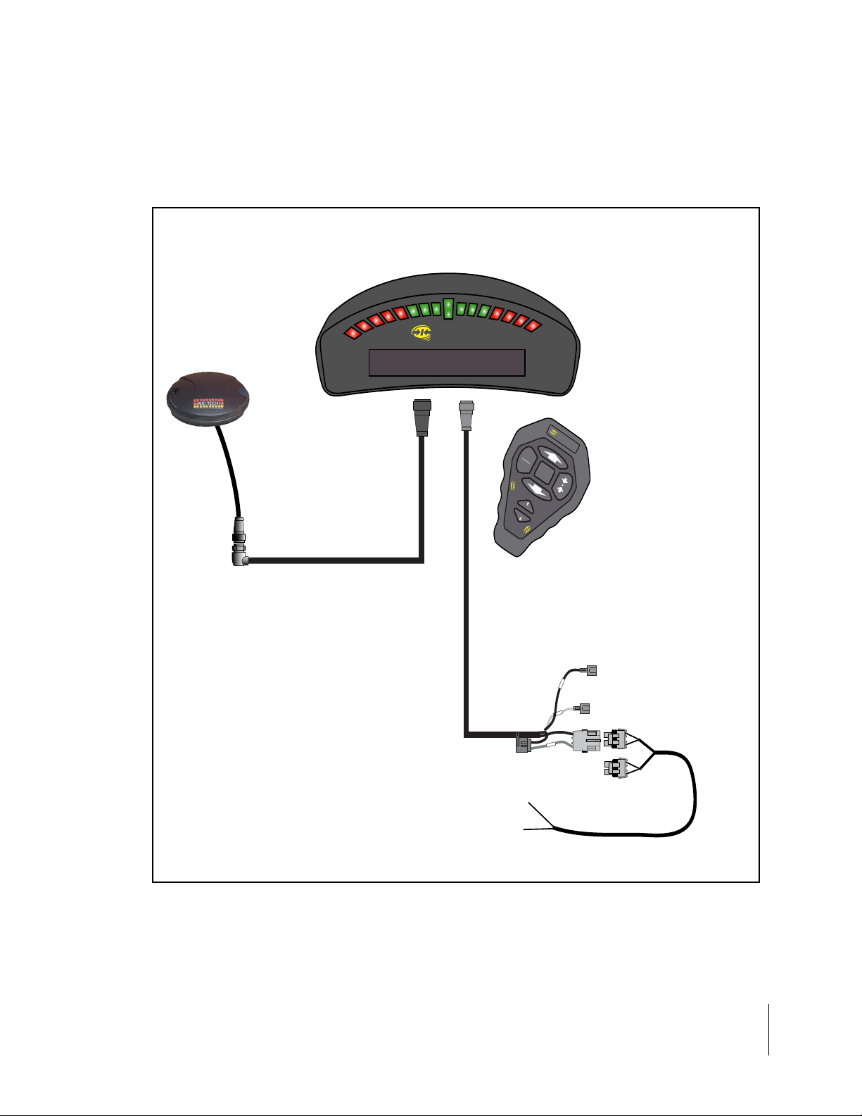
CenterLine Kit with RX 360p WAAS DGPS Receiver
CenterLine Lightbar
CenterLine
CenterLine
MENU
UP
ESC
DOWN
CenterLine
CenterLine
GPS Data Cable
16'
BRIGHT
DIM
CenterLine
CenterLine
Wireless Remote
RX 360p
GPS Receiver
Figure 7: CenterLine Kit with RX360p WAAS DGPS Receiver
CenterLine
Power Cable
12'
5 Amp
To
Battery
Boom Sense -
e
s
n
e
S
Acc
Bat
+12V when booms are ON
Ignition Sense -
+12V when ignition is ON
Power Cable
12'
10 CenterLine
CenterLine Product Kits
Page 17
CenterLine
Software Version 2.00
CenterLine Kit with RX 350p WAAS DGPS Receiver
CenterLine Lightbar
RX 350p
GPS Receiver
CenterLine
GPS Data Cable
16'
CenterLine
CenterLine
Power Cable
12'
M
ESC
CenterLine
BRIGHT
DIM
CenterLine
UP
ENU
D
O
W
N
CenterLine
CenterLine
Wireless Remote
e
s
n
e
S
S
Acc
t
a
B
Boom Sense +12V when booms are ON
Ignition Sense +12V when ignition is ON
5 Amp
To
Power Cable
Battery
Figure 8: CenterLine with RX 350p WAAS DGPS Receiver
CenterLine Product Kits
12'
CenterLine 11
Page 18
CenterLine
Software Version 2.00
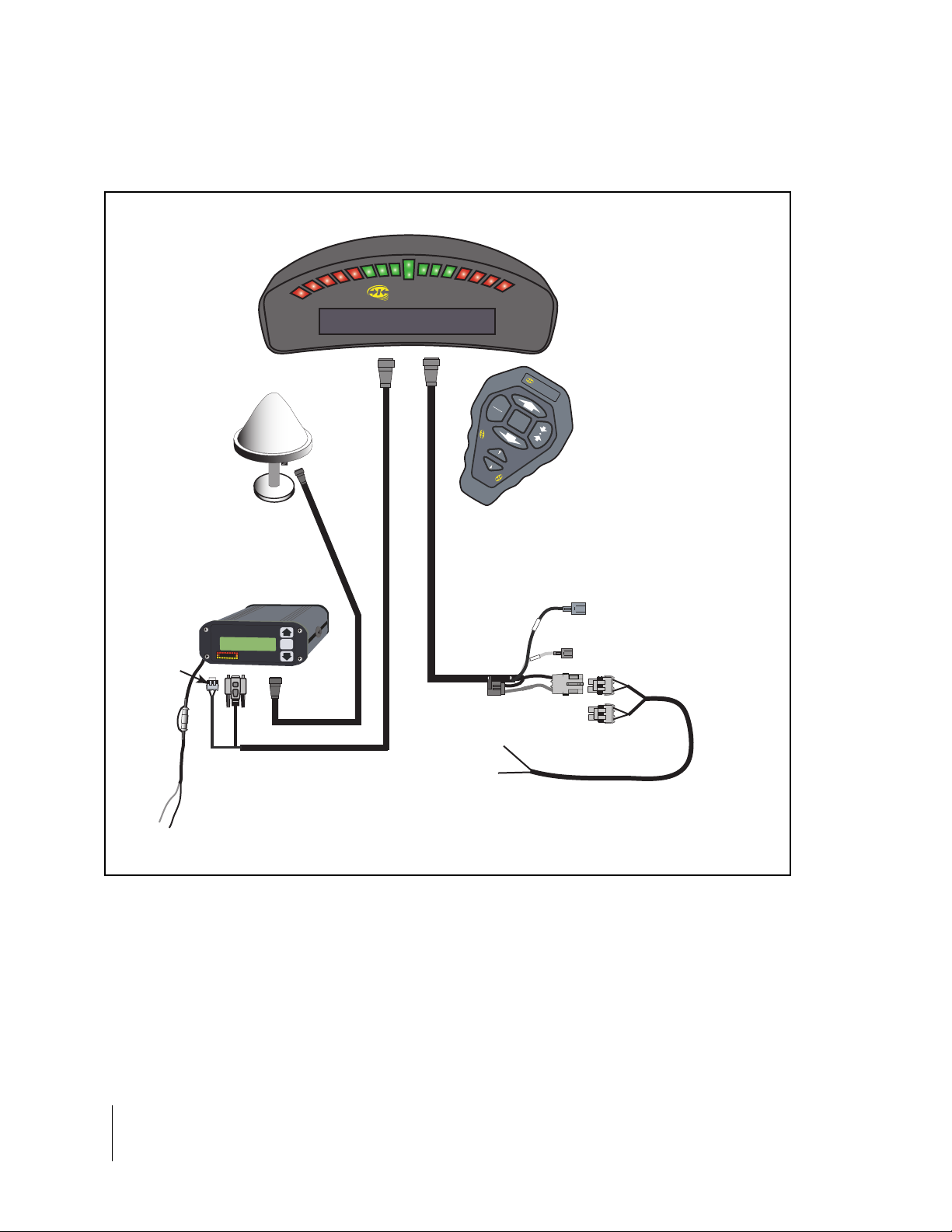
CenterLine with RX 400p DGPS Receiver
CenterLine Lightbar
CenterLine
MENU
ESC
D
O
CenterLine
W
N
BRIGH
T
D
IM
CenterLine
Wireless Remote
CenterLine
UP
CenterLine
Power lead
not used
Inline Fuse
11/2 Amp
+
Red
Flying Leads
GPS Receiver
& Antenna
RX 400p
RX 400p
Lat 5100.120 N+
Lon 11
MID-TECH
-
Blk
RX 400p
CenterLine
Power Cable
12'
se
en
H
igh
A
ccu
D
iffere
ntia
l G
P
202.250 WH
Midwest Technologies, Inc.
racy
S
R
e
ceiver
ENTER
S
cc
A
t
a
B
5 Amp
To
CenterLine
Battery
GPS Data Cable
15'
Figure 9: CenterLine with RX 400p DGPS Receiver
Boom Sense +12V when booms are ON
Ignition Sense +12V when ignition is ON
Power Cable
12'
12 CenterLine
CenterLine Product Kits
Page 19
CenterLine
Software Version 2.00
CenterLine Setup
CenterLine Setup allows the configuring of the CenterLine product to best suit the current guidance and mapping needs. For the complete overview of the Setup process see the "CenterLine
Setup Flow Diagram,” on page 32. CenterLine Setup has three sub-menus: <GUIDANCE>,
<LIGHTBAR>, and <SYSTEM>. Each is described in detail below. Figure 10 shows the Setup
flow.
The top level of CenterLine software has three menus to choose from: <START>, <SETUP>, and
<TOOLS>. To enter the setup menus, use Up or Down to scroll until <SETUP> is visible and press
Enter. When in Setup, scroll through the setup menu list, <GUIDANCE>, <LIGHTBAR>, and
<SYSTEM>, and select the desired setup menu by pressing Enter (See Figure 10).
Figure 10: CenterLine Setup Flow
CenterLine 13
CenterLine Setup
Page 20
CenterLine
Software Version 2.00
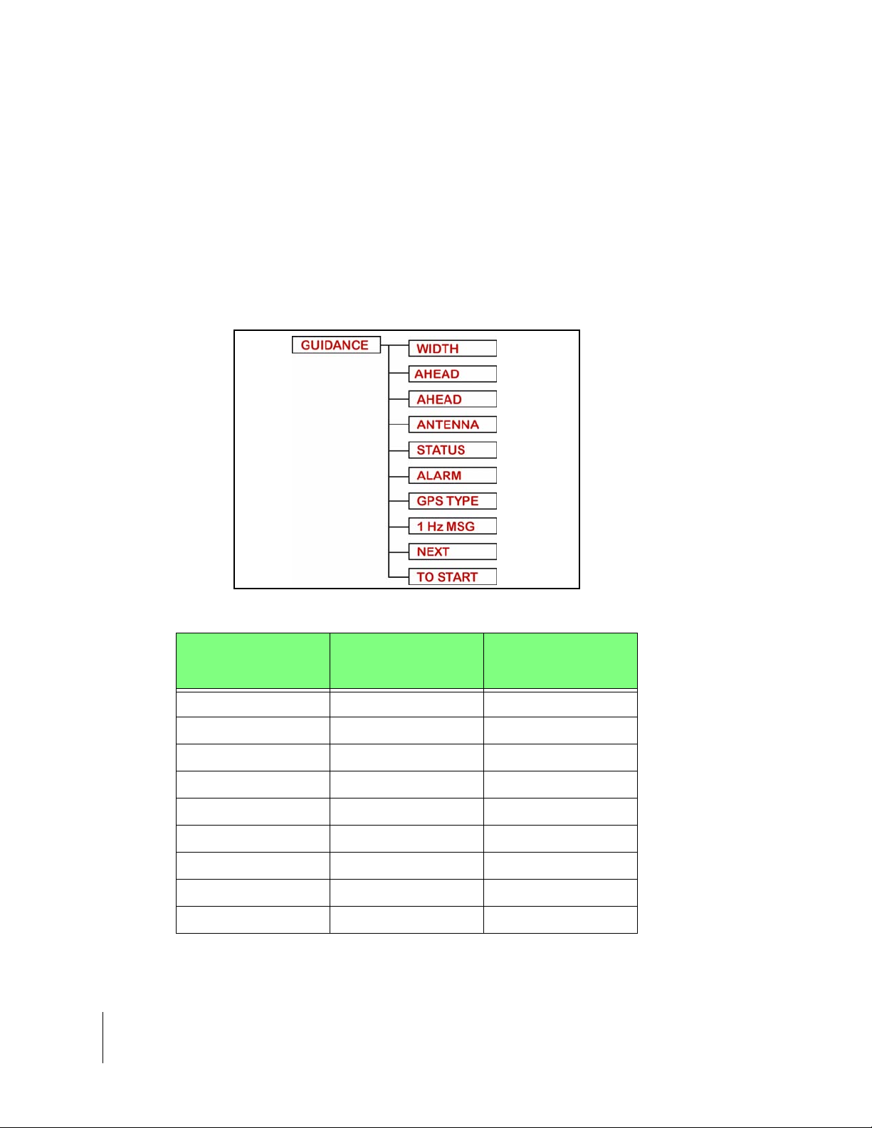
Guidance Setup
Guidance setup allows the setup of several parameters that pertain to guidance functionality. Currently there are four guidance settings (se e Figu re 11).
To access Guidance setup from the Setup menu, scroll until the text window displays <GUIDANCE>, and press Enter. Menu item <WIDTH> should be displayed in the text window . Use Up or
Down to scroll through the list of Guidance setup menu items.
If the first menu item displayed is <SWATH MAN> a Swath Manager 5 has been detected on the
system. See “Swath Manager 5” on page 15 to setup your swath manger 5.
Figure 11: Guidance Setup Flow
Setting Name Default Value
Width 30.0 feet (10 meters) Required
Ahead 1.5 seconds Optional
Antenna -Direction None Recommended
Antenna - Distance 0.0 ft. Recommended
Antenna - Height 9.8 ft. Recommended
Status Detect Off Optional
Alarm Off Recommended
GPS Type DGPS Re commended
1Hz MSG YES Not Recommended
Table 1: Guidance Menu Item De fa ul t Set ti ng s
Change at 1st
Time Start Up
14 CenterLine
CenterLine Setup
Page 21

CenterLine
Software Version 2.00
Swath Manager 5
The Guidance setup parameter Swath Man is only an option when a Swath Manager 5 is connected to the system. If a Swath Manager 5 is not being used ignore this section and continue to
“Width” on page 18.
To adjust the Swath Man setting, go to <GUIDANCE>, scroll with Up or Down until <SWATH
MAN> is displayed, and press Enter. Within the Swath Man menu there are four parameters,
%Overlap, Sections, Width 1-5, and Delay.
Figure 12: Swath Manager 5 Setup
Setting Description
% Overlap
Boom Sections are activated and deactivated based on a percentage of boom in an applied area setting (0%, 50%, 100%).
Sections Enter the number of section 1-5 active on the system.
Width 1-5 Enter the width for each boom 1-5.
Delay
Set a delay in seconds. This will act as a look ahead to turn booms
off and on when entering and exiting an applied zone
Table 2: Swath Man Menu Options
Figure 13: Swath Manager 5 Menu Options
.
CenterLine 15
CenterLine Setup
Page 22

CenterLine
Software Version 2.00
% Overlap
Set the % overlaps to best fit your application 100% overlap will eliminate all skips.
Figure 14: %Overlap Settings
Figure 15: %Overlap Illustration
Sections
Enter the number of sections 1-5.
Figure 16: Number of Sections
Width 1-5
Enter the Width in ft for Boom section 1 and repeat for the remainder of the sections.
NOTE: The total width of all boom sections is NOT the width that will be used for guidance.See “Width” on page 18 to enter the total guidance width.
Figure 17: Boom Section Width
16 CenterLine
CenterLine Setup
Page 23

CenterLine
Software Version 2.00
Delay
Set a delay in seconds. This will act as a look ahead to turn booms off and on when entering and
exiting an applied zone
.
Entering Applied Zone
When entering an applied zone the boom width based on the %overlap must be in the applied
zone the seconds entered in the Delay setup before the boom will be shut off.
Exiting Applied Zone
When exiting an applied zone this setting acts as a look ahead and turns the boo m on prior to exiting an applied zone based on the seconds entered in Delay Setup.
Figure 18: Delay
CenterLine 17
CenterLine Setup
Page 24

CenterLine
Software Version 2.00
Width
The Guidance setup parameter Width is the distance between guidelines. This width is typically
the vehicle implement width or spread width. Setting this width slightly smaller than the actual
width reduces skips. Setting this width slightly larger than the actual width reduces overlap.
To adjust the Width setting, go to <GUIDANCE>, scroll with Up or Down until <WIDTH> is displayed, and press Enter. To increase the width press Up; to decrease the width press Down.
Press Enter when the desired width is set. The width value increments in 0.1 ft. intervals.
Figure 19: Setting the Guidance Width Value
Ahead
The Look Ahead value is the number of seconds ahead of the vehicle you would like the software
to calculate the cross track error. Based on the vehicles speed and trajectory and this look ahead
value, CenterLine can determine where the vehicle will be with respect to the current guideline.
This setting will vary based on the vehicle operators driving ability and preference. This value is
only used with the guidance pattern Parallel. It is not used in Headland curved guidance or the Circle Pivot pattern. A Look Ahead value that fits the operator best will result in smoother guidance
operations. Typically this value is set to 1.5 or 2 seconds
18 CenterLine
CenterLine Setup
Figure 20: Setting the Guidance Ahead Value
Page 25

CenterLine
Software Version 2.00
Antenna
The Antenna sub-menu defines the spatial relati onship between the GPS an tenna a nd the vehicle
implement or delivery point. The GPS antenna should always be mounted along the vehi cle center
line (See Figure 24). The two Antenna menu settings are Direction and Distance.
To enter the Antenna sub-menu, go to <GUIDANCE>, scroll until <ANTENNA> is displayed in the
text window, and press Enter. As mentioned, there are two settings under Antenna: <DIREC-
TION> <DISTANCE> or <HEIGHT>. The text window should display <DIRECTION>. Use Up or
Down to move between the <DIRECTION> <DISTANCE> and <HEIGHT> settings. Press Enter
when the desired setting is in the text window.
Figure 21: Accessing the Antenna Sub-Menu
Direction
The Direction setting is the direction from the GPS antenna to the swath or de livery point (See Figure 24).
To change the Direction setting, go to the Antenna sub-menu of Guidance setup, scroll until
<DIRECTION> is displayed in the text window, and press Enter. Using Up or Down scroll through
the direction pick list (See Figure 22) until the desired direction is displayed in the text window.
Press Enter to save the setting and return to the Guidance setup menu.
DIRECTION BEHIND
FORWARD
Figure 22: Setting the Direction to Swath
Setting Description
Back The swath or delivery point is behind the GPS receiver on
the vehicle along the vehicle center line.
Forward The swath or delivery point is in front of the GPS receiver on
the vehicle along the vehicle center line.
Table 3: Direction to Swath Settings
CenterLine Setup
CenterLine 19
Page 26

CenterLine
Software Version 2.00
Distance
The Distance setting is the distance from the GPS antenna to the swath or delivery location (See
Figure 24).
To adjust the Distance setting, go to the Antenna sub-menu of Guidance setup and press Enter.
Scroll until <DIST ANCE> is displayed in the text window and press Enter. To increase the distance
press Up; to decrease the distance press Down. Press Enter when the desired distance is displayed.
Figure 23: Setting the Distance to the Swath
Height
The Height setting is the From from the GPS antenna to the ground surface.
To change the Height setting, go to the Antenna sub-menu of Guidance setup, scroll until
<HEIGHT> is displayed in the text window , and press Enter. Using Up or Down to enter the height
value until the desired distance is displayed in the text window . Press Enter to save the setting and
return to the Guidance setup menu.
20 CenterLine
CenterLine Setup
Figure 24: Direction and Distance to Swath from DGPS Receiver
Figure 25: Setting the Height of Antenna Value
Page 27

CenterLine
Software Version 2.00
Status
If using a Swath Manager 5 the <STATUS> setting will be removed from the menu setup.
The <ST ATUS> setting is used to auto detect implement status. When the status detect is properly
implemented, the CenterLine detects whether product delivery is on or off, based on the vehicles
product on/off switch. See “CenterLine Product Kits” on page 9 -12 for location of status connect
(boom sense) wiring.
NOTE: When <STATUS> is set to <ON>, +12V must be supplied to the boom sense wire
when booms are on. If this is NOT done applied area detection will NOT work. Reference
the CenterLine wiring tips document 98-01095.
To adjust the Status setting, go to Guidance setup, scroll with Up or Down until <STATUS> is displayed in the text window, and press Enter. Using Up or Down, scroll between the <ON> and
<OFF> settings until the desired setting is displayed in the text window. Press Enter to save the
setting and return to the Guidance setup menu.
Figure 26: Selecting the Status Setting
Setting Description
OFF No Status Detect implemented. Default setting.
ON Status detect assumes a single swath centered on the vehi-
cle.
Table 4: Status Settings
CenterLine 21
CenterLine Setup
Page 28

CenterLine
Software Version 2.00
Alarm
The <ALARM> setting, when set to ON, notifies the operator when entering a previously applied
area. The text window displays <APPLIED> when the implement swath is in a previously applied
area of the field.
To adjust the Alarm setting, go to Guidance setup, scroll until <ALARM> is displayed in the text
window, and press enter. Using Up or Down, scroll between the <ON> and <OFF> settings until
the desired setting is displayed in the text window. Press Enter to save the setting and return to
the Guidance setup menu.
Figure 27: Setting the Alarm
Setting Description
Off No applied area detection.
On Applied are a detection alarm.
Table 5: Status Detect Settings
22 CenterLine
CenterLine Setup
Page 29

CenterLine
Software Version 2.00
GPS Type
GPS Type indicates to the CenterLine system whether the GPS receiver is differentially corrected
or not.
To adjust the GPS Type, go to Guidance setup, scroll until <GPS TYPE> is displayed in the text
window, and press enter. Using Up or Down, scroll between the <DGPS> and <GPS> settings
until the desired setting is displayed in the text window. Press Enter to save the setting and return
to the Guidance setup menu.
Figure 28: Selecting the GPS Type
Setting Description
GPS GPS receiver with no di fferential correction - capable of pro-
viding positioning accuracy of around 10 meters.
DGPS GPS receiver with differential correction - capable of provid-
ing sub-meter positioning accuracy.
Table 6: GPS Types
CenterLine 23
CenterLine Setup
Page 30

CenterLine
Software Version 2.00
1 Hz Msg
A 1 Hz data rate is not recommended for vehicle guidance, so a “GPS Slow” message is sent to
the lightbar to notify the operator if the GPS receiver is set to a 1 Hz data rate. However, there are
some areas where the 1 Hz rate is used. For those areas, we provide the ability to disable the
“GPS Slow” message.
To turn the “GPS Slow” me ssage on or off, go to Guidance setup, scroll until <1 Hz Msg> is displayed in the text window, and press enter. Using Up or Down, scroll between the <YES> and
<NO> settings until the desired setting is displayed in the text window . Press Enter to sa ve the setting and return to the Guidance setup menu.
1 Hz MSG
YES
NO
Figure 29: Selecting the GPS Type
Setting Description
Yes When the data rate of the GPS receiver is set to 1 Hz, a
“GPS Slow” message is sent to the lightbar, and the guidance function is disabled.
No When the data rate of the GPS receiver is set to 1 Hz, a
“GPS Slow” message is sent to the lightbar when you first
enter real-time operation, but guidance is allowed.
Table 7: 1 Hz Msg
24 CenterLine
CenterLine Setup
Page 31

CenterLine
Software Version 2.00
Lightbar Setup
Lightbar setup allows the selection of several parameters related to the lightbar. There are five
lightbar settings: Drive Sensitivity <SPACING>, Display Mode <MODE>, two selectable messages: <TEXT 1> and <TEXT 2>, and <STEER BAR?> (See Figure 30 and Table 8).
Figure 30: The Lightbar Setup Flow
Setting Name Default Value
Spacing 1.5 ft. O ptional
Mode Swath Optional
Text 1 X-Track Error Optional
Text 2 Applied Area Optional
Steer bar? No Optional
Table 8: Lightbar Menu Item Default Settings
Change at 1st
Time Start up
Spacing
The Sp acing setting allo ws the selection of th e dist ance that a single light on the lightbar LEDs represents.
To change the Spacing setting, go to Lightbar setup, scroll until <SPACING> is displayed in the
text window, and press Enter. To increase the spacing distance press UP; to decrease the spacing
press Down. Press the Enter key when the desired spacing is set. The Spacing range is 0.5 ft. to
9.5 ft., in 0.5’ increments.
CenterLine 25
CenterLine Setup
Page 32

CenterLine
Software Version 2.00
Figure 31: Setting the LED Spacing
Mode
The Mode setting defines how the row of LEDs are interpreted. The center stack of Green LEDs
can represent either the current guideline or the vehicle (See Table 9).
To change the Mode setting, go to Lightbar setup, scroll until <MODE> is displayed in the text window, and press Enter. Using Up or Down, scroll through the Mode pick list until the desired setting
is displayed in the text window. Press the Enter key to save the setting an d return to the <TEXT 1>
menu item.
Figure 32: Setting the Mode
Setting Description
Swath When Display Mode is set to Swath, the center stack of Green LEDs represents the cur-
rent guideline. In this mode, steer the vehicle to bring the moving LED back to center
Vehicle When Display Mode is set to Vehicle, the center stack of Green LEDs represents the
vehicle’s position. In this mode, steer the vehicle to bring the center lights towards the
moving LED.
Table 9: Display Mode Settings
Text 1 and Text 2
The Text 1 and Text 2 settings allow you to select text message s from a set of predetermined guidance information messages. These messages are displayed in the lightbar text window for 15 seconds when first enabled, and cycled through during guidance operations. A maximum of two text
messages can be displayed.
26 CenterLine
CenterLine Setup
Page 33

CenterLine
Software Version 2.00
Text 1
To select the Text 1 setting, go to Lightbar setup, scroll using Up or Down until <TEXT 1> is displayed in the text window, and press Enter. Using Up or Down scroll through the Text 1 pick list
until the desired message is displayed in the text window. Press Enter to save the setting and
advance to the <TEXT 2> menu item.
Figure 33: Selecting the Text 1 Message
Message Description
X-Track Displays the error (in distance) between the current guideline and the vehicle position.
Swath # Displays the current guideline number.
Ground Speed Displays the vehicle ground speed.
Area Applied Displays the amount of area covered, sprayed, or spread, in acres or hectares.
COG Course on Ground, displays the vehicle heading in degrees.
Off When Off is selected, no message is displayed in this message slot.
Table 10: Text 1 Options
CenterLine 27
CenterLine Setup
Page 34

CenterLine
Software Version 2.00
Text 2
To select the Text 2 setting, go Lightbar setup, scroll using Up or Down until <TEXT 2> is displayed in the text window, and press Enter. Using Up or Down scroll through the Text 2 pick list
until the desired message is displayed in the text window. Press Enter to save the setting and
advance to the STEER BAR? menu item.
Figure 34: Selecting the Text 2 Message
Message Description
X-Track Displays the error (in distance) between the current guideline and the vehicle position.
Swath # Displays the current guideline number.
Ground Speed Displays the vehicle ground speed.
Area Applied Displays the amount of area covered, sprayed, or spread, in acres or hectares.
COG Course on Ground, displays the vehicle heading in degrees.
Off When Off is selected, no message is displayed in this message slot.
Table 11: Text 2 Message Options
28 CenterLine
CenterLine Setup
Page 35

CenterLine
Software Version 2.00
Steer Bar
The Steer Bar setting determines how the LED steering display appears. The LEDs, representing
the vehicle track in relation to the current guideline, can be shown as a single LED or a solid bar
(See Table 12).
To change the Steer Bar setting, go to Lightbar setup, scroll until <STEER BAR?> is displayed in
the text window, and press Enter. Using Up or Down, scroll through the Steer Bar pick list until the
desired setting is displayed in the text window. Press the Enter key to save the setting and return
to the <SYSTEM> menu item.
Figure 35: Setting the Steer Bar Option
Setting Description
Off
On
The LEDs, representing the vehicle track in relation to the cur rent guideline, are
shown as a single LED.
The LEDs, representing the vehicle track in relation to the cur rent guideline, are
shown as a solid bar.
Table 12: Steer Bar Settings
CenterLine 29
CenterLine Setup
Page 36

CenterLine
Software Version 2.00
System Setup
System setup allows the selection of settings that effect the entire CenterLine product. There are
only two settings: Units and Language (See Table 13).
Figure 36: System Setup
Setting Name Default Value
Unit US Optional
Language English Optional
Table 13: System Menu Item Default Settings
Change at 1st
Time Start Up
Units
System Units allows the selection of either US and Metric units (See Table 14).
To change the System Units, enter System Setup, scroll through the sub-menu list until <UNITS>
appears in the text window, and press Enter. Next scroll between the two units choices, <METRIC> and <US>. When the desired unit is displayed, press the Enter key. The software should
bring you back to <UNITS>.
Figure 37: Setting System Units
30 CenterLine
CenterLine Setup
Page 37

CenterLine
Software Version 2.00
Pick List Description
US All units are entered and displayed in Feet, Miles, and Acres. This is the default setting.
Metric All units are entered and displayed in Meters, Kilometers, and Hectares.
Table 14: The Unit Menu Item Settings
Language
CenterLine comes pre-loaded with several languages. To change the system language, enter System Setup, scroll through the sub-menu list until <LANGUAGE> appears in the text window, and
press Enter. Next scroll to the desired language using Up or Down. When the desired language is
displayed, press the Enter key. The software should return to <NEXT>
Figure 38: Setting the System Language
CenterLine 31
CenterLine Setup
Page 38

CenterLine
Software Version 2.00
CenterLine Setup Flow Diagram
START
SETUP
TOOLS
GUIDANCE WIDTH
AHEAD
AHEAD
30.0 (Default)
1.5 (Default)
1.5 (Default)
ANTENNA DIRECTION
ALARM
GPS TYPE
1 Hz MSG
NEXT
TO START
LIGHTBAR SPACING
MODE
TEXT 1
TEXT 2
STEER BAR
NEXT
TO START
SYSTEM UNITS
NEXT
TO START
LANGUAGE
NEXT
TO START
DISTANCE
HEIGHT
NEXT
OFFSTATUS
ON
OFF
ON
DGPS
GPS
YES
NO
1.5 (Default)
VEHICLE
SWATH
X-TRACK
SWATH#
SPEED
AREA
COURSE
OFF
NO
YES
METRIC
US
FORWARD
BACK
0.0 (Default)
9.8 (Default)
ENGLISH
SWEDISH
DANISH
DUTCH
GERMAN
FRENCH
ITALIAN
PORTUGUESE
SPANISH
POLISH
32 CenterLine
CenterLine Setup
Figure 39: CenterLine Setup Flow Diagram
Page 39

CenterLine
Software Version 2.00
Tools
The Tools menu contains several functions to provide some basic system diagnostics (See Table
15).
To access Tools from the Setup menu, scroll until the text window displays <TOOLS>, and press
Enter. <RECEIVER> should be displaye d in the text window. Use Up or Down to scroll through
the Tools menu.
Figure 40: The Tools Menu Flow
Menu Item Description
Receiver Checks the status of a connected GPS receiver.
Lightbar Tests the functionality of the CenterLine Lightbar LEDs and
text window.
e-DIf Only appears if an e-Dif GPS receiver is detected by the
CenterLine system. Re-calibrates the e-Dif receiver.
e-Dif Info Only appears if an e-Dif GPS receiver is detected by the
CenterLine system. Displays current position information.
Demo Activates a simulated CenterLine session.
Next Advances to the next Setup menu item.
To Start Returns the operator to the Start point of the menu.
Table 15: Tools Menu Items
CenterLine 33
Tools
Page 40

CenterLine
Software Version 2.00
Receiver
The Receiver diagnostic test queries the attached GPS receiver an d returns its current configuration and status. This information is displayed in the text window on the lightbar.
To start the Receiver check, go to the T ools menu, scroll until <RECEIVER> is displayed in the text
window, and press Enter. The lightbar displays the diagnostic messages shown in Table 16.
Diagnostic Description
GPS Status If the lightbar is not receiving GPS data, the text window message
appears as <NO GPS>. If the lightbar is receiving GPS data but no
differentially corrected GPS data, the text window message appears
as <GPS>.
DGPS Status If the lightbar is receiving differential corrected GPS data, the text win-
dow message appears as <DGPS>.
NMEA Strings Returns the name of each NMEA string currently being received from
the receiver. As an example if the NMEA GPGGA string is being
received from the receiver then the text window displays <GGA>.
Data Rate Returns the current receiver data rate. This is typically 5 Hz. The rate
is displayed in the text window, e.g. <5 HZ> is displayed for the 5
Hertz data rate.
Table 16: Receiver Diagnostic Messages
Lightbar
The Lightbar diagnostic test initiates an illumination sequence of all of the LEDs and the text window, followed by a brightness control sequence. This allows the verification that all lights on the
CenterLine lightbar are working properly.
To start the Lightbar check, go to <TOOLS> and press Enter. Scroll with Up or Down until
<LIGHTBAR> is displayed in the text window and press Enter. The illumination sequence should
start. When test is completed the lightbar displays <END>.
e-Dif
The accuracy of the position information provided by the e-Dif GPS receiver slowly deteriorates
with time since the last calibration. Because of this, it is recommended that the e-Dif receiver be
recalibrated about every 1 to 2 hours, to maintain the accuracy of the position information. The eDif tool allows the operator to re-calibrate the e-Dif receiver by coming to a stop and selecting e-Dif
in the Tools menu or the Real time menu.
To re-calibrate the e-Dif receiver, go to <TOOLS> and press Enter. Scroll with Up or Down until
<E-DIF> is displayed in the text window and press Enter. The text window displays <WAIT> until
the receiver re-calibration is complete. The lightbar then displays <READY>.
34 CenterLine
Tools
Page 41

CenterLine
Software Version 2.00
e-Dif Info
The “e-Dif Info” function only appears when the CenterLine system detects that an e-Dif GPS
receiver is present and calibrated. This receiver diagnostic test queries the attached e-Dif GPS
receiver and displays current position information being gen erated. This information is displayed in
the text window on the lightbar.
To start the e-Dif diagnostic test, go to the Tools menu, scroll until <E-DIF INFO> is displayed in
the text window, and press Enter. The lightbar displays the diagnostic messages shown in Table
17.
Diagnostic Description
Number of
Satellites
E Correction Age Displays the time since the last re-calibration.
Current Last
Position
Displays the number of satellites that are providing a reliable signal to
the GPS receiver.
Displays the latitude and longitude and height of the last re-calibration
position.
Table 17: e-Dif Receiver Diagnostic Messages
Demo
The Demo mode displays simulated guidance information on the lightbar. This is used primarily by
sales personnel to domonstrate the capabilities of the CenterLine system.
Next
The Next selection saves the setup information and returns the operator to the Start point on the
CenterLine menu.
To Start
The Start selection saves the setup information and returns the operator to the Start point on the
CenterLine menu.
CenterLine 35
Tools
Page 42

CenterLine
Software Version 2.00
CenterLine Real-Time Operation
Starting Real-time Operation
This section assumes that the setup section (See “CenterLine Setup” on page 13) has been read
and the CenterLine lightbar properly set up.
Start real-time operation by pressing Enter when <START> is displayed in the text window. The
<START> menu item is at the highest menu level. <START> can be easily reached from most
menu levels by scrolling to <TO START> and pressing Enter. This jumps to the <START> location
from anywhere in the menu structure (See Figure 39).
Figure 41 is a flow diagram of the CenterLine real-time operation a nd menu.
START
TOOLS
NEW?
RESUME?SETUP
PATTERN
NEW AB MARK A MARK B
A+
AREA
E-DIF WAIT
EXIT
APPLY OFF? APPLY ON?
HEADLAND
RIGHT
LEFT
STRAIGHT
CLOSE
CURVED
Real-time Menu
Figure 41: Real-Time Operation Flow Diagram
New? Resume?
When Enter has been pressed at the <START> location, a prompt to start a new field or resume
working in the current field appears. During real-time operation, CenterLine stores the vehicle’s
trajectory data. This allows the operator to stop working in a field before finished and return at a
later time, continuing where they left off. Only the current field is stored.
Use Up or Down to scroll between the <NEW?> and <RESUME?> menu items. Selecting
<NEW?> clears the current field trajectory data and starts a new field in memory. Selecting
<RESUME?> retains the current field trajectory data and allows the start of guidance using the
existing data.
36 CenterLine
CenterLine Real-Time Operation
Page 43

CenterLine
Software Version 2.00
Real-time Operation
Real-time guidance begins when <NEW?> or <RESUME?> is selected. At this point, the GPS receiver should
be properly connected to the CenterLine lightbar and running. See Figures 7-9 for diagrams showing how the
DGPS receiver should be connected. The default guidance mode is Straight-Line Guidance and the current
guidance mode is displayed in reverse video. The current guideline information is stored in memory, along
with the field’s trajectory data, is lost when <NEW?> is selected, and retained when <RESUME?> is selected.
Only information for a single guideline is stored. While in Headland mode, A and B points can be marked for
Straight-Line or Curved AB guidance.
Real-time Menu
During real-time operation, a real-time menu (See Figure 41 on page 36) is available that allows
you to switch between guidance patterns, mark A and B points for straight-line or Curved AB guidance, start a new A-B line, and exit. The real-time men u is accessed by p ressing Up or Down during guidance operation. When either of these keys is pressed, the guidance messages displayed
in the text window are replaced by the real-time menu (See Figure 41 on page 36). Use Up and
Down to scroll through the menu and press Enter to select an item. The real-time menu times out
when 5 seconds have passed and no arrow keys have been pressed.
Apply On/Off
If no switchbox or boom sense cable is being used and the <GUIDANCE><STATUS> setting (See
“St atus” on page 21) is set to off, Apply On/Off information must be provided to the CenterLine system manually. To toggle the Apply On/Off status, scroll the real-time menu (See Figure 41 on
page 36) until <Apply on> or <Apply off> appears in the text window. Pressing Enter switches to
the status displayed.
NOTE: This does not turn the application on and off. It only notifies the CenterLine system
of the application status. <Apply on> and <Apply off> do not appear if <GUIDANCE><STATUS> is set to ON.
CenterLine 37
CenterLine Real-Time Operation
Page 44

CenterLine
Software Version 2.00
Marking A and B Locations
The Straight-lin e and Curve AB guid ance mode s require a reference guideline to g uide the vehicle
along. Establishing a guideline involves marking two points along the reference guideline. To
establish this reference guideline using the real-time menu, use Up or Down to scroll in the menu
until <NEW AB?> is displayed on the lightbar (See Figure 42), and press Enter. The menu item
<MARK A> is displayed. Mark the A location by pressing Enter when the desired location is
passed. The menu item <MARK B> is now displayed. To mark the B location, press Enter when
the desired location is passed. The reference guideline is now establishe d an d the lightb ar displays guidance information. See the underlined caution under “
page 49, when establishing AB guideline for Curve AB operation.
Curve AB Guidance Operation” on
NEW AB? MARK A MARK B
Figure 42: The Mark A Mark B Sequence
Switching between Guidance Modes
There may be situations where it is necessary to switch between guidance modes. Typically an
operator makes one or more passes around the field’s headland area in the Headland guidance
mode. While driving the headlands, the operator may mark the A and B guideline points to be used
when switching modes. When the headlands are completed, the operator switches to the Straightline or Curve AB mode, and completes the field in a back and forth fashion.
To switch between guidance modes, scroll the real-time menu (See Figure 41 on page 36) until <HEADLAND>, <STRAIGHT>, or <CURVE AB> appears in the text window. When the desired mode is displayed,
press Enter to make it active.
38 CenterLine
CenterLine Real-Time Operation
Page 45

CenterLine
Software Version 2.00
A+ Feature
At any time after a guideline is created, the guidance line can be shifte d to the current position by
activating the “A+” feature. The heading (and shape, if in curved mode) of the original guideline is
maintained, but the A/B line is shifted to the vehicle location. Scroll the real-time menu until <A+>
is displayed and Press Enter to activate the shift.
A+
Figure 43: Area Determination Flow Diagram
Area Determination
The area of the current job or field is important information. CenterLine allows the determination of
the area of a field by driving the perimeter of the field. This can be conveniently done while driving
the first headland circuit in Headland mode.
To deter mine the are a of a field, scr oll th e re al- tim e men u un til <AREA> is displayed (See
Figure 4 4 on page 39) and Press Enter. The lightbar displays <LEFT> or <RIGHT>. Using Up or
Down, select the side of the swath or implement that is closest to the field boundary. Press Enter
to start area calculation. The lightbar displays <
close the boundary, scroll the real-time menu (Figure 41) until <CLOSE> is displayed. Press Enter
to close the boundary and determine the area. Pressing <CLOSE> insert s a line between the st arting location and the current location and uses that shape to determine area.
The area is automatically determined when the vehicle drives within 4.5 meters (15 feet) of the
starting point.
The bounded area is displayed on the lightbar as a p art of the guidance message stream for three
minutes and when stopped in an “applied” area.
If a bounded area has already been determined, the <VIEW> menu item is present. Pressing
Enter at the <VIEW> level displays the current bounded area value.
Map BND> or <Map BND
>. When ready to
Figure 44: Area Determination Flow Diagram
CenterLine Real-Time Operation
CenterLine 39
Page 46

CenterLine
Software Version 2.00
Return to Point
CenterLine allows the operator to mark a point in the field to return to later in time. Typically the Return to Point feature is used to mark a location when stopping guidance and
wanting to start in the same location and in the same direction at a later time. This Return
to Point location is stored with the field’s trajectory data, is lost when <NEW?> is selected,
and retained when <RESUME?> is selected.
There is a specific Return to Point key located on the wireless remote, see Figure 4. This key
works in toggle fashion; press it once to mark the point (the lightbar displays <ÎÍ>), press it
again to navigate back to the point. Stop the navigation process by pressing ESC. When Return
to Point is pressed again (third time) the old location is replaced with the current vehicle location.
While operating in the Return to Point mode, no active text messages are displayed except error
messages. If the vehicle enters an area that has already been applied, the display alternates
between the Return To Point distance and <Applied!>.
Exiting Real-time Operation
To exit guidance, press Esc or scroll with Up or Down in the real-time menu until <EXIT?> is displayed (Figure 45) in the text window and Pres s Enter. <BYE> appears in the text window, realtime operation stops, and the display returns to the main menu.
40 CenterLine
CenterLine Real-Time Operation
Figure 45: Exit in Display
Page 47

CenterLine
Software Version 2.00
Headland Guidance Operation
This section describes how to operate CenterLine in the Headland guidance mode. The Headland
mode is used when the operator wants to drive several circuits around the field boundary and be
guided around all circuits that occur after the first. When several headland circuits have been completed, the operator has the option of switching to the Straight-line mode. The Headland pattern is
also used when a user wants to do product application on terraced fields. In the Headland curved
guidance pattern, the operator can pull along side any previous applied swath and be guided parallel to that swath by the X-Track guidance display.
To select the Headland guidance mode, scroll with Up or Down in the real-time menu until
<HEADLAND> is displayed. If <HEADLAND> is not displayed in reverse video, press Enter. This
switches the guidance mode to Headland. If <HEADLAND> is displayed in reverse video, the system is already in Headland mode.
Reference Guideline
While operating in the Headland mode, the user has the option to mark the A and B points of the
reference guideline used in the Straight-line or Curve AB Guidance mode. This feature makes it
easier for the operator to Mark the A and B points while in Headland mode applying the headlands.
It is always best to mark the A and B points for the Straight-line or Curve AB mode while driving
along a straight edge of a field. See the underlined caution under “
on page 49, when establishing AB guideline for Curve AB operation. For more detail on how to
establish a reference guideline see “Marking A and B Locations” on page 38.
Curve AB Guidance Operation”
The operator remains in the Headland mode until the guidance mode is changed using the realtime menu (see “Switching between Guidance Modes” on page 38). The reference guideline can
be used for Straight-line and Curve AB mode.
Headland Pattern Example
In this example the operator wants to apply two headland passes to the field and then switch to
Straight-line mode and apply the remainder of the field with straight-line parallel swath guidance.
After the first headland circuit the operator pulls parallel to the first circuit swath and begins applying the second circuit while being guided parallel to the first circuit.
Figure 4 6 on page 42 shows the operator just finishing the first headland circuit. When the operator pulls along side the first headland circuit, curved guidance automatically st art s . The ope rator is
now able to drive the second headland circuit parallel to the first circuit by following the guidance
information displayed on the lightbar.
Figure 47 on page 42 shows the operator being guided along side the initial headland circuit. The
lightbar automatically supplies guidance information. For more details on how to interpret curved
guidance information on the lightbar (See “Headland Mode Lightbar Graphics” on page 45).
Figure 4 8 on page 43 shows the operator continuing to drive around the second headland circuit.
CenterLine 41
CenterLine Real-Time Operation
Page 48

CenterLine
Software Version 2.00
Figure 46: Completing the First Headland Circuit
42 CenterLine
CenterLine Real-Time Operation
Figure 47: Starting the Second Headland Pass
Page 49

CenterLine
Software Version 2.00
Figure 48: Continuing Around the Second Circuit.
Switching from Headland to Straight-line Mode
When the operator has completed the desired number of headland circuits, two circuits in our current example, the system is switched to Straight-line Guidance mode to apply the r emainder of the
field in a straight back and forth fashion.
To switch from the Headland Pattern to another pattern, see “Switching between Guidance Modes”
on page 38. If the operator is being guided along a curved path when th e pattern is switched, the
lightbar no longer guides them along the curved path.
If a reference guideline was established while in the Headland Guidance mode, CenterLine automatically guides the vehicle along the closest parallel line as soon as the operator switches to the
Straight-line mo de. If a reference guideline was not established during the Headland mode, then
the operator must mark the A B points. The lightbar displays the <MARK A> message, indicatin g
that no reference guideline exists.
Figure 49 shows the operator applying product in Straight-line mode. Because a reference guideline was established during the curved guidance process, the user can immediately start straightline guidance as soon as the guidance mode button is pressed.
CenterLine 43
CenterLine Real-Time Operation
Page 50

CenterLine
Software Version 2.00
Figure 49: Switched from Headland Mode to Straight-line Mode.
Figure 50: Completed Field App lic at io n
Figure 50 shows the completed field. Notice that there are several areas of the field where the
operator turned spray off to avoid double application on previously applied areas.
44 CenterLine
CenterLine Real-Time Operation
Page 51

CenterLine
Software Version 2.00
Headland Mode Lightbar Graphics
CenterLine’s Headland mode guidance techniq ue employs a lightbar text displa y graphic that aids
the operator when navigating parallel to a curved swath. The X-Track LED functionality that is
employed in Straight-line and Curve AB modes is also employed when driving in Headland mode.
A projected swath-path graphic is displayed in the text display area of the lightbar (See Figure 51).
This projected path is made up of four horizontal bars. The bottom bar represents the path closest
to the vehicle and the top bar is the path furthest away. The width of the bar s decrease as they
move away from the vehicle to add a perspective view to the path ahead of the vehicle. The projected distance of the first bar from the front of the vehicle is ba sed on the vehicle speed. The ligh tbar in Figure 51 informs the user to drive straight, and there are no turns approach ing. In Figure 52
the lightbar indicates the vehicle is approaching a turn to the right. Th e X-Track LEDs indicate that
the vehicle is slightly to the right of the guideline. Ligh tbar X-T rack LEDs are set up in Swath mode .
Therefore the user must correct to the left to get back on line. The X-Track LEDs do not provide
any information relating to the curved path ahead of the vehicle, they only indicate where the vehicle is with respect to the guideline at the current vehicle location. The lightba r displays a “hollow”
path during the first headland pass to indicate that no guidance information is available yet (The
first pass must be completed before a parallel path can be established) (See Figure 53).
CenterLine 45
CenterLine Real-Time Operation
Page 52

CenterLine
Software Version 2.00
Figure 51: Curved Guidance Lightbar Graphics
46 CenterLine
CenterLine Real-Time Operation
Figure 52: Right-Hand Turn Ahead
TM
CenterLine
Figure 53: Hollow Path
Page 53

CenterLine
Software Version 2.00
Straight-line Guidance Operation
The Straight-line guidance mode provides vehicle guidance along straight lines, based on a reference guideline. The first step is to establish the reference guideline. This reference guideline is
used to calculate all other parallel guidelines. See “Marking A and B Loca tions” on page 38 for
more detail on how to establish a reference guideline.
To mark the initial point A, begin driving along the first swath path. Typica lly this is alon g a straight
edge of a field boundary. While the vehicle is driving along the initial swath, the lightbar displays
<MARK A>. As the vehicle passes over the desired A location, press Enter to establish the guide-
line point A.
The lightbar now displays <MARK B>. The next step is to establish guideline point B. To do this,
press Enter as the vehicle passes over the desired B location. This establishes the reference
guideline. The lightbar starts displaying X-Track guidance information as well as any user selected
messages defined in Lightbar setup (See “Lightbar Setup” on page 25). If the vehicle is too far
from the previously applied area to determine guidance information, a “Hollow” path is displayed
(See Figure 53 on page 46).
When the reference guideline is established, the oper ator can begin driving stra ight-line guidan ce.
The CenterLine software detects which guideline is closest to the centerline of the vehicle and pr ovides guidance information with respect to that line. As the vehicle moves across the field (Figure
54) new guidelines, parallel to the reference guideline, are established based on the swath width
value entered in Guidance setup.
Figure 54: Working a Field in the Straight-line Guidance Mode
CenterLine Real-Time Operation
CenterLine 47
Page 54

CenterLine
Software Version 2.00
When making a turn at the end of the field, the lightbar displays the dist ance to the next swath ( see
Figure 55).
CenterLine
30.0 FT
CenterLine
27.2 FT
CenterLine
14.7 FT
Figure 55: Distance to Next Straight Swath
48 CenterLine
CenterLine Real-Time Operation
Page 55

CenterLine
Software Version 2.00
Curve AB Guidance Operation
The Curve AB guidance mode works similar to Straight-Line mode except it provides vehicle guidance along curved lines, based on a curved reference guideline. The first step is to establish the
reference guideline. This reference guideline is used to calculate all other parallel guidelines. See
See “Marking A and B Locations” on page 38 for more detail on how to establish a reference
guideline.
To mark the initial point A, begin driving along the first swath path (See Figure 56). It is recom-
mended that the reference guideline be established along the longest side of the field, if
possible, because the curved guidelines do not extend beyond the A and B poin ts (See Figure 57). Beyond the A and B points straight-line guidance will be implemented. While the
vehicle is driving along the initial swath, the lightbar displays <MARK A>. As the vehicle passes
over the desired A location, press Enter to establish the guideline point A.
Figure 56: Marking AB Line in Curved Guidance
Figure 57: Curve AB Mode guideline limitations
CenterLine Real-Time Operation
CenterLine 49
Page 56

CenterLine
Software Version 2.00
The lightbar now displays <MARK B>. The next step is to establish guideline point B. To do this,
press Enter as the vehicle passes over the desired B location. This establishes the reference
guideline. The lightbar starts displaying X-Track guidance information as well as any user selected
messages defined in Lightbar setup (See “Lightbar Setup” on page 25). If the vehicle is too far
from the previously applied area to determine guidance information, a “Hollow” path is displayed
(See Figure 53 on page 46).
When the reference guideline is established, the operator can begin driving Curve AB guidance.
The CenterLine software detects which guideline is closest to the centerline of the vehi cle and provides guidance information with respect to that line. As the vehicle moves across the field (Figure
56) new guidelines, parallel to the reference guideline, are established based on the swath width
value entered in Guidance setup. When making a turn at the end of the field, the lightbar displays
the distance to the next swath (see Figure 58).
CenterLine
30.0 FT
CenterLine
27.2 FT
CenterLine
14.7 FT
Figure 58: Distance to Next Curved Swath
50 CenterLine
CenterLine Real-Time Operation
Page 57

CenterLine
Software Version 2.00
Applied Area Detection
CenterLine allows the detection of a previously applied area. To use applied area detection, the
Lightbar Setup - Alarm menu field must be set up prior to starting guidance. See “Alarm” on page
22 of this User Guide for more details on how to set up this menu field.
Detecting A Previously Applied Area
Figure 59 shows how previously applied area detection works. As the vehicle enters a previously
applied area, the lightbar displays the message APPLIED, even if the application is turned off.
When the vehicle exits the previously applied area, the APPLIED message stops displaying.
Figure 59: Applied Area Detection in Headlands
CenterLine Real-Time Operation
CenterLine 51
Page 58

CenterLine
Software Version 2.00
Detecting Neighboring Swath
Applied area detection notifies the user when the vehicle crosses into a previously applied neighboring swath. Figure 60 shows an Applied Area Overlap example. The vehicle can overlap up to
25% of the Swath Width without being notified. Once the edge of the vehicle swath overlaps 25%
or more into a neighboring swath, the lightbar displays <APPLIED>.
Figure 60: Applied Area Overlap in Neighboring Swath
52 CenterLine
CenterLine Real-Time Operation
Page 59

CenterLine
Software Version 2.00
Lightbar Index
The CenterLine lightbar is capable of displaying a considerable amount of information to the user.
This information can be represented as text in the display window, illuminated cross track LEDs, or
a combination of text and lights. Information displayed on the lightbar depends on both user
defined settings and system warnings not controlled by the user. Table 18 describes each possible
lightbar state and possible information that could be displayed.
Lightbar State Description
Mark A: Displayed when establishing the guidance point
A of the reference guideline.
Mark B: Displayed when establishing the guidance point
B of the reference guideline.
Swath #: A user selected lightbar message. When not
on the initial guideline the first character is either L or R
for Left and Right of the initial guideline. The number
identifies how many lines left or right of the initial guideline.
X-Track Error: A user defined lightbar message. This
cross track error message is displayed when the vehicle
is on the guideline and there is no error.
X-Track Error: A user defined lightbar message. In this
example the operator should steer to the left 2.3 ft.
(Assuming that System Units is set to US and Lightbar
is set to Swath mode.)
Table 18: CenterLine Lightbar Index
CenterLine 53
Lightbar Index
Page 60

CenterLine
Software Version 2.00
Lightbar State Description
Ground Speed: A user defined lightbar message indicating the vehicle speed in Miles per Hour (MPH). System
Units is set to US.
Ground Speed: A user defined lightbar message indicating the vehicle speed in Kilometers per Hour (KPH).
System is Units set to Metric.
Course on Ground (COG): A user defined lightbar message indicating the vehicles heading in degrees 0 to
359. The example to the left indicates the vehicle’s
course on the ground is due South (180 degrees).
Area Applied: A user defined lightbar message indicating the current amount of area applied in Acres. System
Units is set to US.
Area Applied: A user defined lightbar message indicating the current amount of area applied in Hectares. System Units is set to Metric.
Applied Area Detection: This message is displayed
when the vehicle is within a previously applied area.
Note that the Red stop light (far ri ght light) is illu minated.
See “Applied Area Detection” on page 51.
Table 18: CenterLine Lightbar Index
54 CenterLine
Lightbar Index
Page 61

CenterLine
Software Version 2.00
Lightbar State Description
Curved guidance information graphics. The four horizontal bars in the text display represent a perspective
view of the swath ahead of the vehicle. The bars skew
left or right to represent the curved path ahead.
Curved guidance information graphics. The path in the
text display represents a perspective view of the swath
ahead of the vehicle. The “hollow path” indicates that
the vehicle is making the first headland pass and no
guidance information is available yet. The path skews
left or right to represent the curved path ahead. This is
also displayed when in guidance mode but the vehicle is
not moving.
Mapping Boundary: This message is displayed when
the user is mapping the field boundary. The arrow symbol on the left indicates the field boundary is on the left
side of the vehicle.
CenterLine
NO GPS
Mapping Boundary: This message is displayed when
the user is mapping the field boundary. The arrow symbol on the right indicates the field boundary is on the
right side of the vehicle.
System Warning: The message is displayed when there
is loss of differential GPS corrections. Guidance calculations are stopped until differential corrections resume.
System Warning: This message is displayed when there
is a complete loss of GPS signal to the GPS receiver or
Smartpad. Guidance calculations are stopped until
DGPS signal resumes.
Table 18: CenterLine Lightbar Index
CenterLine 55
Lightbar Index
Page 62

CenterLine
Software Version 2.00
Lightbar State Description
Ver 1.07
Lightbar Version Message: This message is displayed
when the user starts up CenterLine or runs the Lightbar
Test. This number varies and is based on lightbar version and model.
CenterLine
Table 18: CenterLine Lightbar Index
56 CenterLine
Lightbar Index
Page 63

CenterLine
Software Version 2.00
Swath Manager 5 Operation
Starting Swath Manager 5
This section assumes that the setup section (See “Swath Manager 5” on page 15) has been read
and the CenterLine lightbar is properly set up.
Star t by reviewin g the installation diagrams below to make sure the system is pr ope rly connected.
Make sure the controller and Swath Manager 5 switches are all in the proper location See “Swath
Manager 5 Auto Boom Engage:” on page 58.
Create a boundary to lock the area of application. If a boundary is created and closed and the Auto
Boom switch is set to engaged the system will NOT apply outside of the boundary. See “A+ Feature” on page 39 to learn how to create a boundary.
Installation
Not Used
GPS IN
MASTER
ON
OFF
ON
P
RO
AUTO MAN
CenterLine
SM5 to CenterLine
45-05461
54321
BOOM CONTROL
Swath Manager 5
78-08065
Rate Controller
Cable
SPRAYER CONTROL
DISENGAGE
AUTO
BOOM
ENGAGE
Swath Manager 5
844-x
Automated Boom
Section Control
Power
Cable
45-05324
IGN Sense
GPS IN
Not Used
Existing switches or switchbox
SM5 Controller Harness
TeeJet - 45-05462
Raven - 45-05463
Existing
Controller Harness
Status Detect
(Not used)
Valves
Figure 61: Installation of Swath Manager 5
MASTER
CenterLine
Cable
SM5 to CenterLine
45-05461
54321
BOOM CONTROL
Swath Manager 5
78-08065
AUTO
BOOM
ENGAGE
Swath Manager 5
Automated Boom
Section Control
DISENGAGE
Wire Splice
50-10097
Power
Cable
45-05324
IGN Sense
Status Detect
(Not used)
SM5 Harness,
Exsisting Switches or Switchbox
45-05467
To Ac c. Pow er
or Battery
Valves
CenterLine 57
Swath Manager 5 Operation
Page 64

CenterLine
Software Version 2.00
Swath Manager 5 Auto Boom Engage:
• Rate Controller section switches must be OFF.
• Rate Controller section switches in the ON position override the Swath Manager 5.
• Rate Controller master switch must be in the ON position.
• Rate Controller master switch in the OFF position overrides the Swath Manager 5.
• Swath Manager 5 master switch and section switches must be in the ON position.
• Swath manager 5 auto boom switch must be set to engage.
Swath Manager 5 Auto Boom Disengage
• Both switches for a particular section (the one on the controller and the one on the
Swath Manager 5) must be off in order for that section to be off.
• Swath manager 5 auto boom switch must be set to Disengaged.
• Section Status is still passed to the Centerline when Auto Boom has been
disengaged.
Rate Controller
Swath Manager 5
MASTER
BOOM CONTROL
Master & Boom Sections ON
Figure 62: Switch Settings to Engage Swath Manager 5
54321
AUTO
BOOM
ENGAGE
Swath Manager 5
DISENGAGE
Auto Boom
Engaged
Automated Boom
Section Control
RO
P
Hold 2 sec.
Auto
Man
Press to DEFAULT
Hold to CLEAR
MASTER
Master ON
AUTO
CAL
P
TeeJet VisiFlo color coding only. For other tips see manual.
12345
Boom Sections OFF
®
Tee et
J
58 CenterLine
Swath Manager 5 Operation
Page 65

Page 66

Midwest Technologies
2864 Old Rochester Road
Springfield, IL 62703
 Loading...