

Page 1
CenterLine
U s e r G u i d e
98-05054
Page 2

Page 3

USER GUIDE
Software Version 1.05
98-05054
R2
Page 4

CenterLine
Software Version 1.05
Copyrights
© 2002 Midwest Technologies Illinois, LLC. All rights reserved. No part of this document or the computer
programs described in it may be reproduced, copied, photocopied, translated or reduced in any form or by
any means, electronic or machine readable, recording or otherwise, without prior written consent from Midwest Technologies.
Trademarks
Unless otherwise noted, all other brand or product names are trademarks or registered trademarks of their
respective companies or organizations.
Limitation of Liability
MIDWEST TECHNOLOGIES ILLINOIS, LLC PROVIDES THIS MATERIAL “AS IS” WITHOUT WARRANTY OF ANY KIND, EITHER EXPRESSED OR IMPLIED. NO COPYRIGHT LIABILITY OR
PATENT IS ASSUMED. IN NO EVENT SHALL MIDWEST TECHNOLOGIES BE LIABLE FOR ANY
LOSS OF BUSINESS, LOSS OF PROFIT, LOSS OF USE OR DATA, INTERUPTION OF BUSINESS, OR
FOR INDIRECT, SPECIAL, INCIDENTIAL, OR CONSEQUENTIAL DAMAGES OF ANY KIND,
EVEN IF MIDWEST TECHNOLOGIES HAS BEEN ADVISED OF SUCH DAMAGES ARISING FROM
TEEJET SOFTWARE.
ii
Page 5

CenterLine
Software Version 1.05
Table of Contents
Introduction........................................................................................................................2
About CenterLine ..........................................................................................................2
What’s new in Version 1.05 ..........................................................................................3
Corrections to the Ver. 1.0 User Guide .........................................................................3
About this User‘s Guide ................................................................................................4
Wireless Remote Control...............................................................................................6
CenterLine Lightbar.......................................................................................................7
CenterLine Quick Start-up ...............................................................................................8
General Start-up Sequence.............................................................................................8
First Time Start-up Sequence ........................................................................................8
CenterLine Product Kits ...................................................................................................9
CenterLine Kit without DGPS Receiver........................................................................9
CenterLine Kit with RX 360p WAAS DGPS Receiver ..............................................10
CenterLine Kit with RX 350p WAAS DGPS Receiver ..............................................11
CenterLine with RX 400p DGPS Receiver .................................................................12
CenterLine Setup .............................................................................................................13
Guidance Setup ............................................................................................................14
Lightbar Setup..............................................................................................................19
System Setup................................................................................................................24
CenterLine Setup Flow Diagram .................................................................................26
Tools ..................................................................................................................................27
Receiver .......................................................................................................................27
Lightbar........................................................................................................................28
CenterLine Real-Time Operation ..................................................................................29
Starting Real-time Operation .......................................................................................29
Real-time Operation.....................................................................................................30
Real-time Menu ...........................................................................................................30
Return to Point .............................................................................................................33
Exiting Real-time Operation ........................................................................................33
Headland Guidance Operation.....................................................................................34
Straight-line Guidance Operation ................................................................................40
Applied Area Detection ...............................................................................................41
Lightbar Index .................................................................................................................43
iii
Page 6

CenterLine
Software Version 1.05
iv
Page 7
CenterLine
A lightbar guidance system with wireless remote control.
Software Version 1.05
CenterLine
MENU
ESC
CenterLine
CenterLine
UP
DOWN
CenterLine
Midwest Technologies IL, LLC
CenterLine
Page 8

CenterLine
Software Version 1.05
Introduction
About CenterLine
CenterLine is a low-cost lightbar guidance system, controlled by a wireless remote. CenterLine
provides accurate straight-line and curved guidance, for use in spraying, seeding, and other
related jobs at a cost that rivals foam markers. The CenterLine product comes with a combination
Beacon/WAAS or WAAS only DGPS receiver, providing sub-meter, pass to pass, positioning accu
racy. The wireless remote control is used to set-up and operate the system through menus and
options displayed on the lightbar.
CenterLine‘s attractive design combines a compact size with easy to see LEDs that are fully
adjustable. Using dedicated buttons on the wireless remote, the lightbar can be dimmed to effi
ciently run at night and brightened to be easily seen in full sunlight.
Straight or Curved Guidance
CenterLine guides along swaths of all kinds with sub-meter, pass to pass, accuracy. Select the
driving pattern and CenterLine determines the closest swath to follow. There‘s no need to decide a
guidance pattern ahead of time, or to commit to a pattern for the entire job. Centerline allows the
switching of patterns in real-time, determining when a new pattern is being used and keeping the
operator informed of the current status.
-
-
Wireless Remote Control Unit
CenterLine‘s ergonomic, handheld, remote control is easier to use than most TV remotes. Seven
easy to read keys allow the scrolling of menus displayed on the lightbar. The remote keypad is
backlit for night-time operation, and 3 AAA batteries (included) powers the unit for an entire sea
son.
The small, powerful, remote permits mounting the weather-resistant lightbar outside on the hood
or in the cab. When mounted outside, wireless communication permits easy operation while the
cab stays clean and sealed from dust and contaminants.
-
Lightbar Shows you the Information You Want
A text display on the lightbar reports a choice of guidance information. It also warns when an area
of the field is entered that has already been applied. Guidance text information can be turned off, if
preferred. Choose two of these guidance messages to monitor progress in real-time:
• Cross-Track Error,
• Current Swath Number,
• Vehicle Speed,
• Applied Area,
• Vehicle course on the ground.
2
CenterLine
Introduction
Page 9

CenterLine
Software Version 1.05
What‘s new in Version 1.05
• The lightbar is now 15% brighter. This makes the lightbar display easier to read in bright sunlight.
• A new lightbar display option has been added. The Steer Bar option makes the LED steering
display easier to see (See —Lightbar Setup“ on page 19).
• All text messages (not warnings, alarms, or guidance info) are now displayed for 15 seconds
when first enabled (See —Text 1 and Text 2“ on page 20).
• The Applied! message is displayed when crossing into an applied area, even if application is
turned off (See —Applied Area Detection“ on page 41).
• The Bounded Area is now displayed when stopped in an applied area (See —Area Determination“ on page 31).
• Í©È now appears in the lightbar text display to confirm that the —Return To Point“ button
was pressed (See —Return to Point“ on page 33).
• In —Return to Point“ mode, no active text messages are displayed (only error messages) (See
—Return to Point“ on page 33).
• —Return To Point“ mode now works in swath mode as well as headland mode.
•The Exit? message is now displayed to confirm desire to exit the guidance function (See —Exit-
ing Real-time Operation“ on page 33).
• A —Hollow“ path is now displayed:
• in Headland Mode, during the first headland pass, to indicate that no guidance information
is available yet (See —Headland Guidance Operation“ on page 34).
• during Straight Mode when the distance to the previously applied area is too far to deter-
mine a guidance path (See —Straight-line Guidance Operation“ on page 40).
• X-Track information is now displayed in Headland Mode (See —Headland Guidance Operation“
on page 34).
Corrections to the Ver. 1.0 User Guide
• Clarification of the connection of the Implement Status line (See —Status“ on page 17).
• Corrected Setup Flow Diagram (Added —Steer Bar) (See —CenterLine Setup Flow Diagram“ on
page 26).
• Correction of the Receiver GPS Status messages (See —Receiver“ on page 27).
• Corrected Real-Time Operation Flow Diagram ( Corrected default mode to —Straight“, changed
—Boundary“ label to —Area“, added —Apply Off?“ and —Apply On?“) (See Figure 30 on page 29).
• Clarification of default guidance mode (See —Real-time Operation“ on page 30).
• Added description of —Apply On/Off (See —Apply On/Off“ on page 30).
CenterLine
Introduction
3
Page 10
CenterLine
Software Version 1.05
About this User’s Guide
This is revision 2 of the CenterLine user‘s guide and covers CenterLine software versions 1.05 to
1.99. Some software versions may come with a supplement to this user‘s guide.
Menu Items and Pick List Text
Throughout this user‘s guide, menu item text is displayed between the <> characters, For example, <START>. Keys on the remote (See Figure 4 on page 6) are denoted in bold italics, such as
Enter.
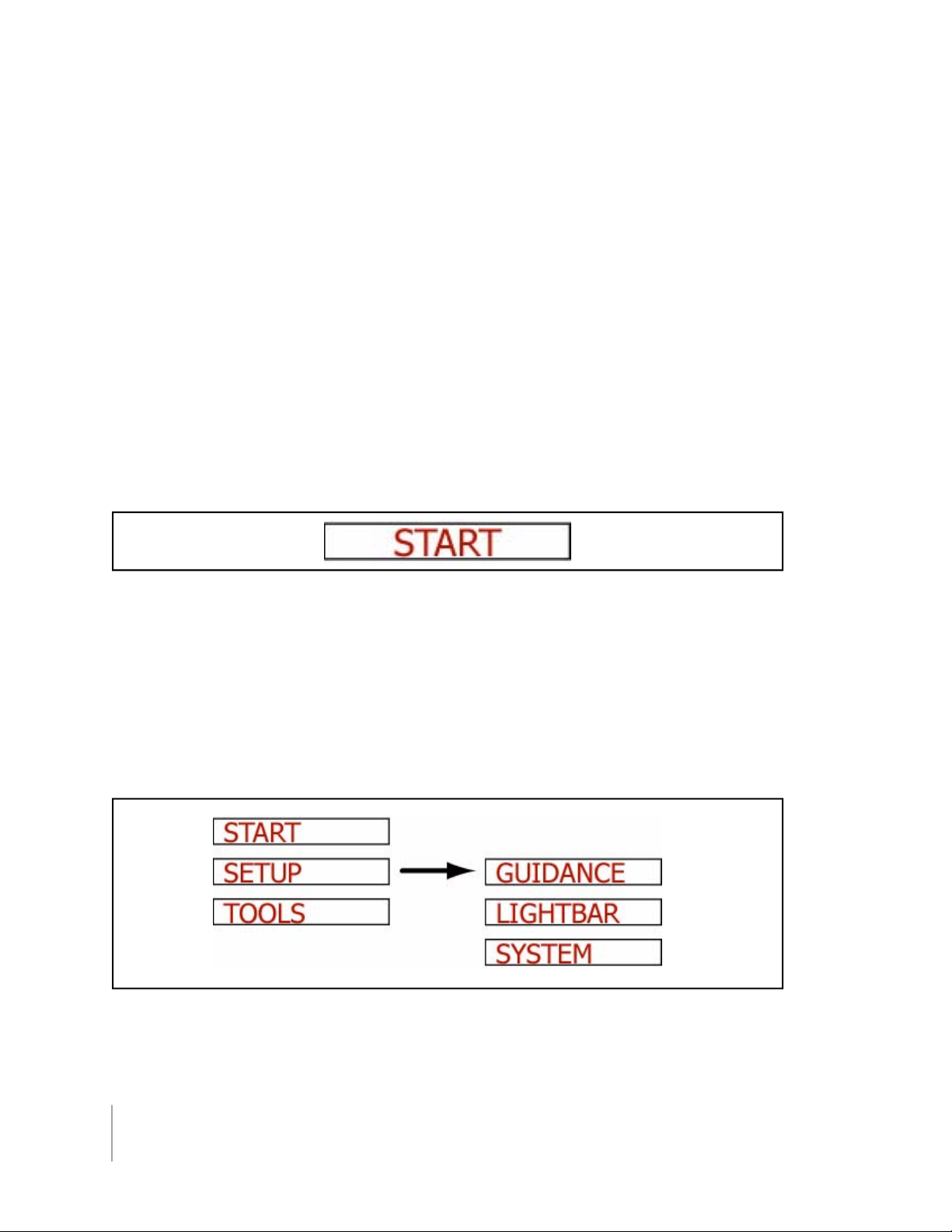
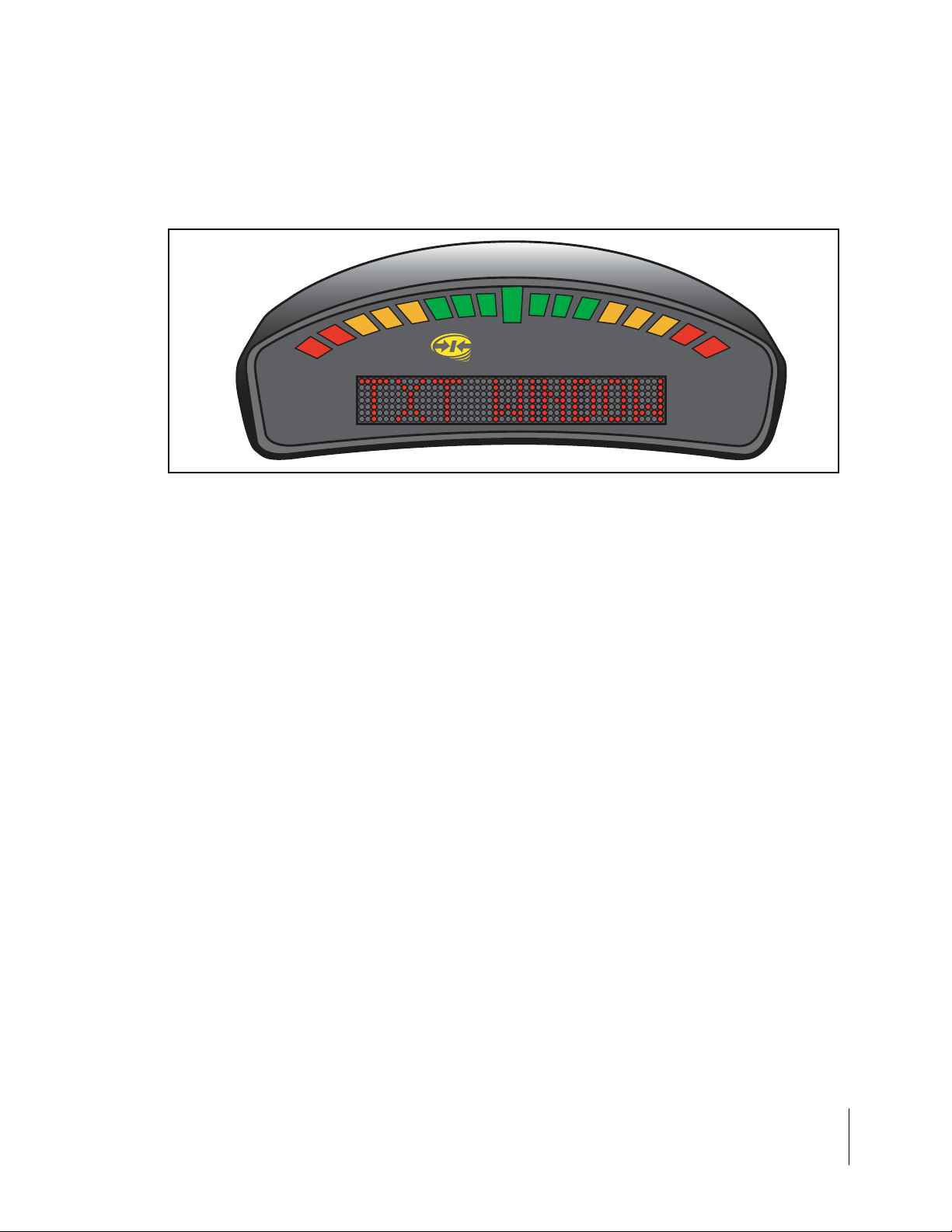
Most of the figures in this user‘s guide are of menu items that are displayed in the text window of
the lightbar (See Figure 5 on page 7). This text represents either a menu item, such as <GUID
ANCE> or a pick-list item, such as <METRIC>. The lightbar text window can display a single line
of text up to ten characters long. Figure 1 shows an example of a single text line that would be dis
played on the lightbar.
-
-
Figure 1: Example of Text Displayed on Lightbar
Figures with multiple menu items are depicting the menu items that are above, below, left, and
right of the text line currently in view. Figure 2 shows several menu items. The current menu item
in view is <SETUP> and is denoted with a black arrow to the right side of the text. This figure is
showing that the Up and Down arrow keys can be used to scroll between <START>, <SETUP>,
and <TOOLS>. If the Enter key on the remote is pressed, the display moves to the <GUIDANCE>
setup menu item. This figure also shows that, from the <GUIDANCE> menu item, it is possible to
scroll between the <GUIDANCE>, <LIGHTBAR>, and <SYSTEM> setup menus using the Up and
Down arrow keys.
Figure 2: Displaying Multiple Text Lines
4
CenterLine
Introduction
Page 11
CenterLine
Software Version 1.05
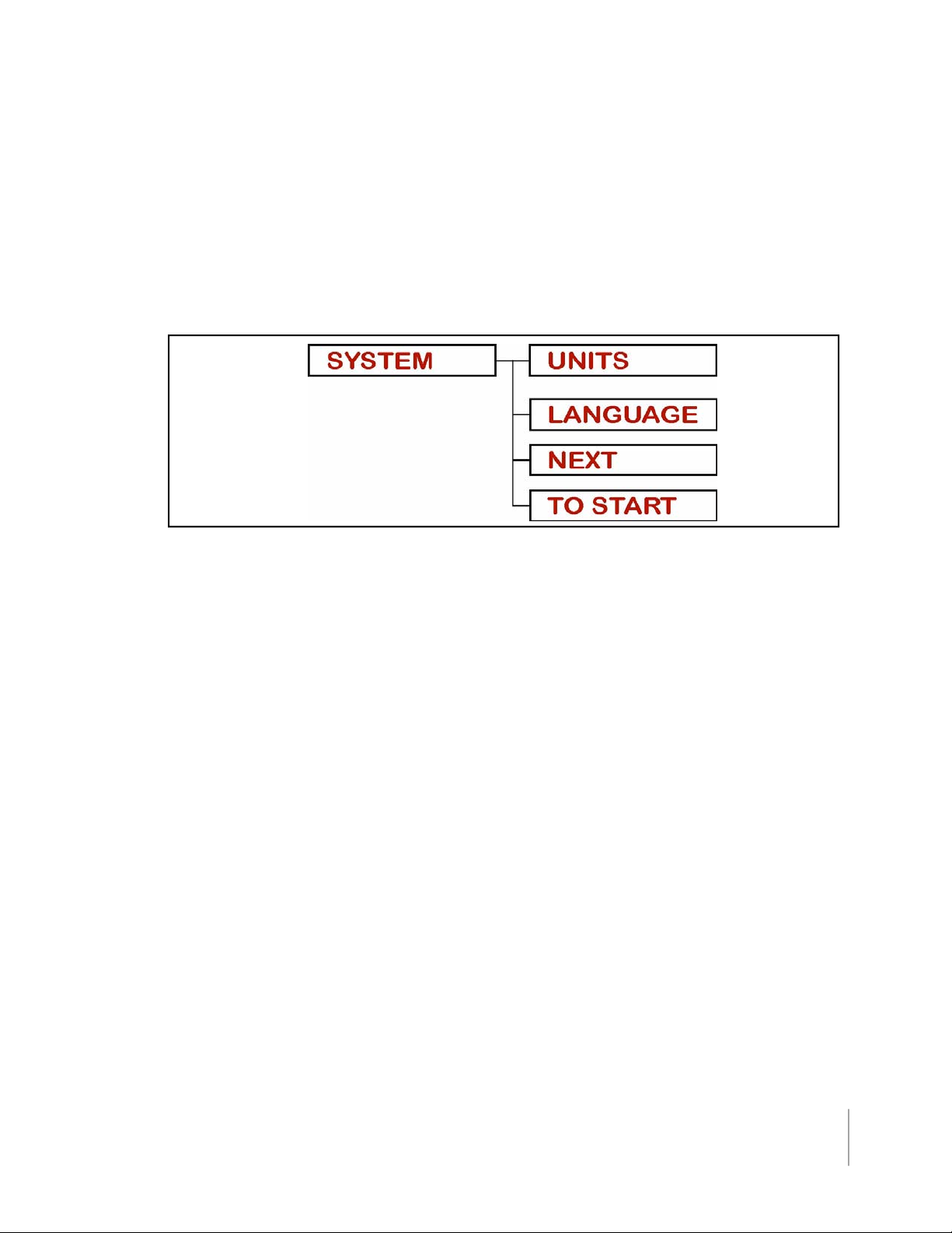
Menu Items Next and To Start
There are two additional menu items that are found in almost every menu; <NEXT> and <TO
START>. Figure 3 shows the <NEXT> and <TO START> menu items in the System Setup menu
list. Pressing Enter at <NEXT> brings up the next menu heading. As an example, pressing Enter
at <NEXT>, while in Lightbar setup, brings up <SYSTEM>. In the same example, pressing ESC at
<NEXT> brings up the <LIGHTBAR> menu Item. Selecting <TO START> automatically goes back
to the <START> menu. From here real-time guidance can be started. Using <TO START> is useful
when it is necessary to quickly change one setting and then go right back into real-time operation.
Figure 3: Next and To Start Menu Items
Software Components
CenterLine software can be broken into three components: Setup (See —CenterLine Setup“ on
page 13), Real-Time (See —CenterLine Real-Time Operation“ on page 29), and Tools (See —Tools“
on page 27). Setup allows the configuring of the CenterLine to best suit the current needs, and the
Real-Time component handles all of the real-time guidance operations. The Tools component pro
vides basic diagnostics for the lightbar and the attached GPS receiver.
-
CenterLine
Introduction
5
Page 12
CenterLine
Software Version 1.05
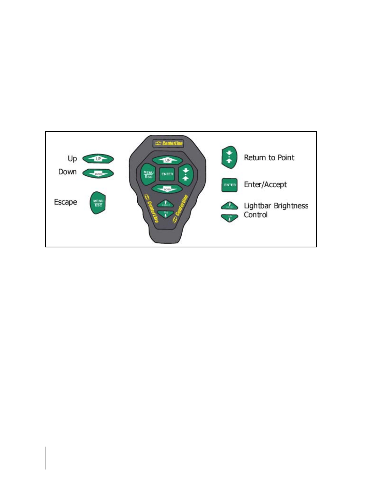
Wireless Remote Control
General Operation
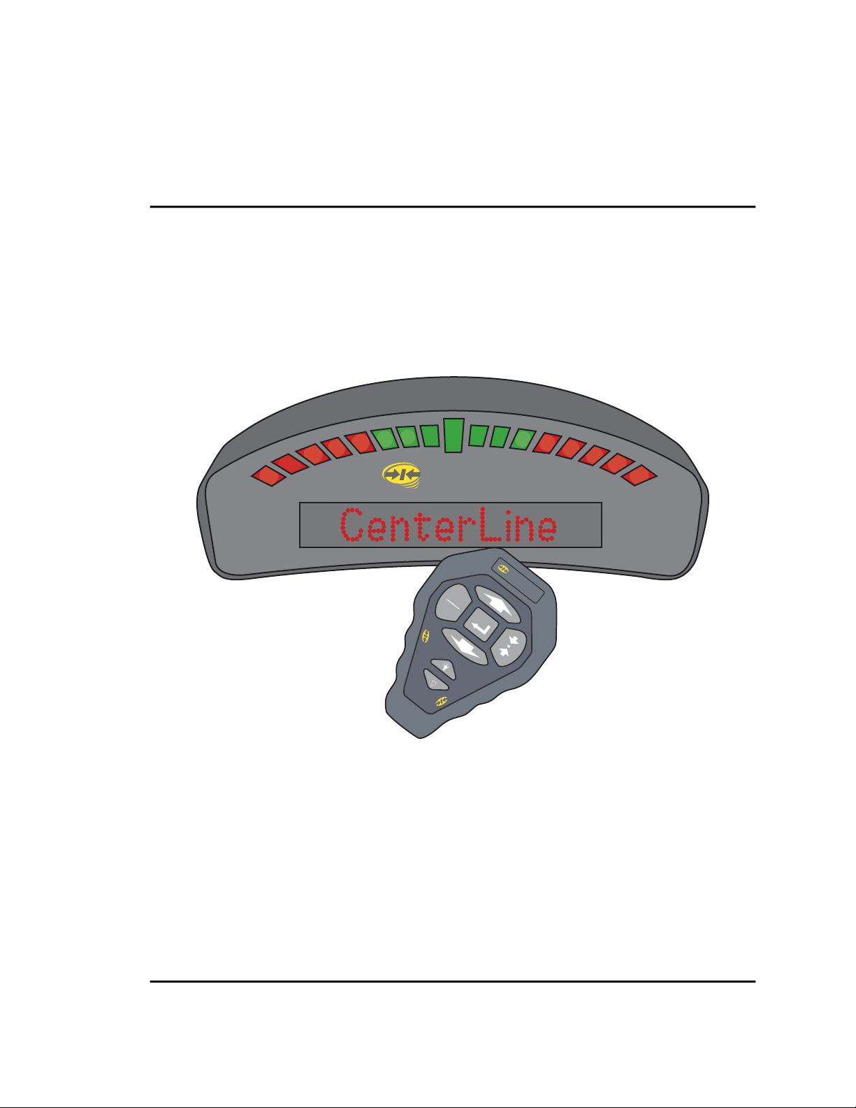
Operation of CenterLine software is via remote keypad input and menu items displayed in the text
display area (See Figure 5) of the CenterLine lightbar. The Up and Down arrow keys are used to
scroll through menus, sub-menus, and pick lists. The Enter key is used to enter menus and sub
menus, and accept a desired pick-list entry. The ESC key acts as cancel.
-
Figure 4: The Wireless Remote Control Unit
FCC Statement
This device complies with part 15 of the FCC Rules. Operation is subject to the following two conditions: (1) This device may not cause harmful interference, and (2) this device must accept any
interference received, including interference that may cause undesired operation.
QS7CL7850094
QS7CL7850107
TR19JN96.008
Changes or modifications to the product, not expressly approved by Midwest Technologies Illinois,
LLC, could void the user's authority, as granted under Part 15 of the FCC Rules, to operate the
equipment.
6
CenterLine
Introduction
Page 13
CenterLine
Software Version 1.05
CenterLine Lightbar
TM
CenterLine
Figure 5: The CenterLine Lightbar
Lightbar Specifications
Housing Material: ABS/Poly carbonate alloy construction.
Dimensions: 3.70“H x 9.40“W x 3.80“D (95 mm x 240 mm x 100 mm)
Weight: 0.8 lbs (0.36 kg)
Processor: Intel StrongARM
MEMORY: 16 MB Ram, 2 MB Flash
LEDs: High-lumen red, yellow, and green radial light pattern and 10 character
LED alpha-numeric text display. Full brightness control adjustment using
wireless remote.
Operating Temp: 32 to 160 F (0 to 70 C)
Storage Temp: -40 to 185 F (-40 to 85 C)
I/O to DGPS: 1 asynchronous RS 232
I/O to Control Unit: Wireless link operating at 433 MHz. FCC part 15 and Industry Canada
RSS-210 certified. Other certifications pending.
Mounting: Mounting bracket supplied. Magnetic and suction mounts are optional.
CenterLine 7
Introduction
Page 14

CenterLine
Software Version 1.05
CenterLine Quick Start-up
The following section assumes that your CenterLine hardware has been properly set up. See
—CenterLine Product Kits“ on page 9 - 12 for information on how to configure the system.
General Start-up Sequence
• Apply power to CenterLine.
• Lightbar performs a start up sequence.
• Lightbar displays current software version.
• Lightbar displays <START>.
• <START> display should remain until Enter is pressed to start real-time guidance or the Start
menu is scrolled, using Up or Down to move to another menu option, <SETUP> or <TOOLS>.
First Time Start-up Sequence
• Apply power to CenterLine.
• Lightbar performs a start up sequence.
• Lightbar displays current software version.
• Lightbar displays <START>.
• Using Up or Down, scroll until <SETUP> is displayed on the lightbar. Press Enter.
• Run through the three setup sub-menus <GUIDANCE>, <LIGHTBAR>, and <SYSTEM>. It is
important to have the correct swath width entered.
• Return to the <START> location and press Enter to begin real-time guidance.
8
CenterLine
CenterLine Quick Start-up
Page 15
CenterLine
Software Version 1.05
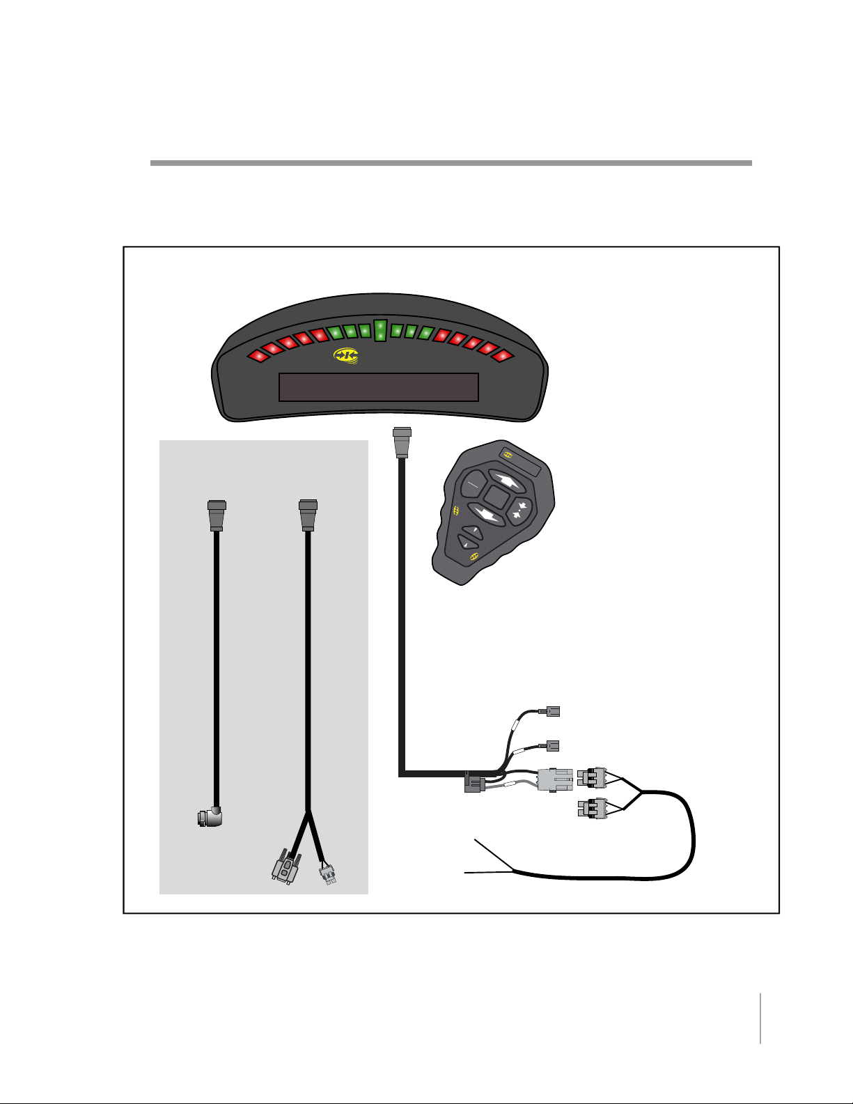
CenterLine Product Kits
CenterLine Kit without DGPS Receiver
CenterLine Lightbar
CenterLine
A GPS data cable is
required but not provided in kit.
M
EN
U
ESC
DOWN
CenterLine
BRIGHT
DIM
CenterLin
CenterLine
Power Cable
12'
5 Amp
To
Battery
CenterLine
UP
e
CenterLine
Wireless Remote
Boom Sense -
e
s
n
e
S
Acc
t
a
B
+12V when booms are ON
Ignition Sense -
+12V when ignition is ON
Power Cable
12'
Figure 6: CenterLine without DGPS Receiver
CenterLine
CenterLine Product Kits
9
Page 16
CenterLine
Software Version 1.05
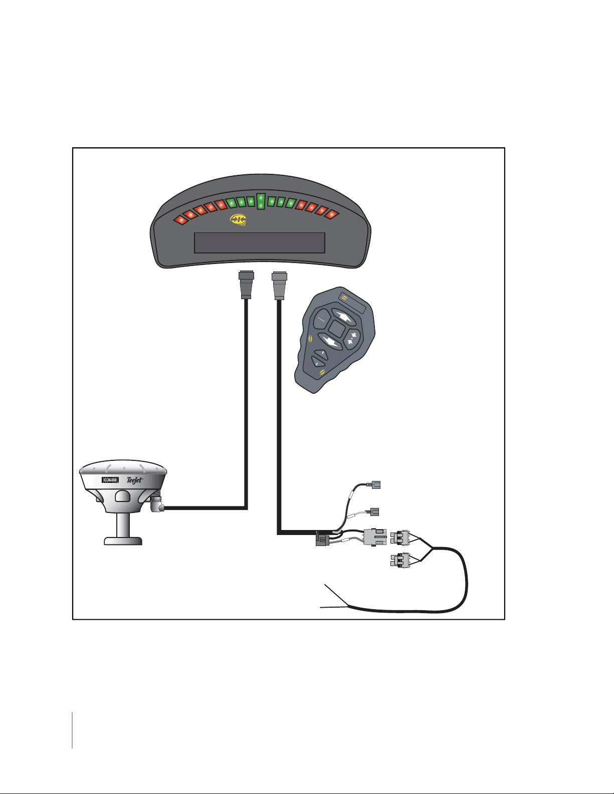
CenterLine Kit with RX 360p WAAS DGPS Receiver
CenterLine Lightbar
CenterLine
CenterLine
MENU
UP
ESC
DOWN
CenterLine
CenterLine
GPS Data Cable
16'
BRIGHT
DIM
CenterLine
CenterLine
Wireless Remote
RX 360p
GPS Receiver
Figure 7: CenterLine Kit with RX360p WAAS DGPS Receiver
CenterLine
Power Cable
12'
5 Amp
To
Battery
Boom Sense -
e
s
n
e
S
Acc
Bat
+12V when booms are ON
Ignition Sense -
+12V when ignition is ON
Power Cable
12'
10
CenterLine
CenterLine Product Kits
Page 17
CenterLine
Software Version 1.05
CenterLine Kit with RX 350p WAAS DGPS Receiver
CenterLine Lightbar
CenterLine
RX 350p
GPS Receiver
CenterLin
MENU
ESC
e
UP
1 Amp
10'
6'
6'
CenterLine GPS
Data Cable
15'
DOWN
CenterLine
BRIGHT
DIM
CenterLin
CenterLine
Power Cable
12'
5 Amp
To
Battery
e
CenterLine
Wireless Remote
Boom Sense -
e
s
n
e
S
S
Acc
t
a
B
+12V when booms are ON
Ignition Sense -
+12V when ignition is ON
Power Cable
12'
Figure 8: CenterLine with RX 350p WAAS DGPS Receiver
CenterLine Product Kits
CenterLine
11
Page 18

CenterLine
Software Version 1.05
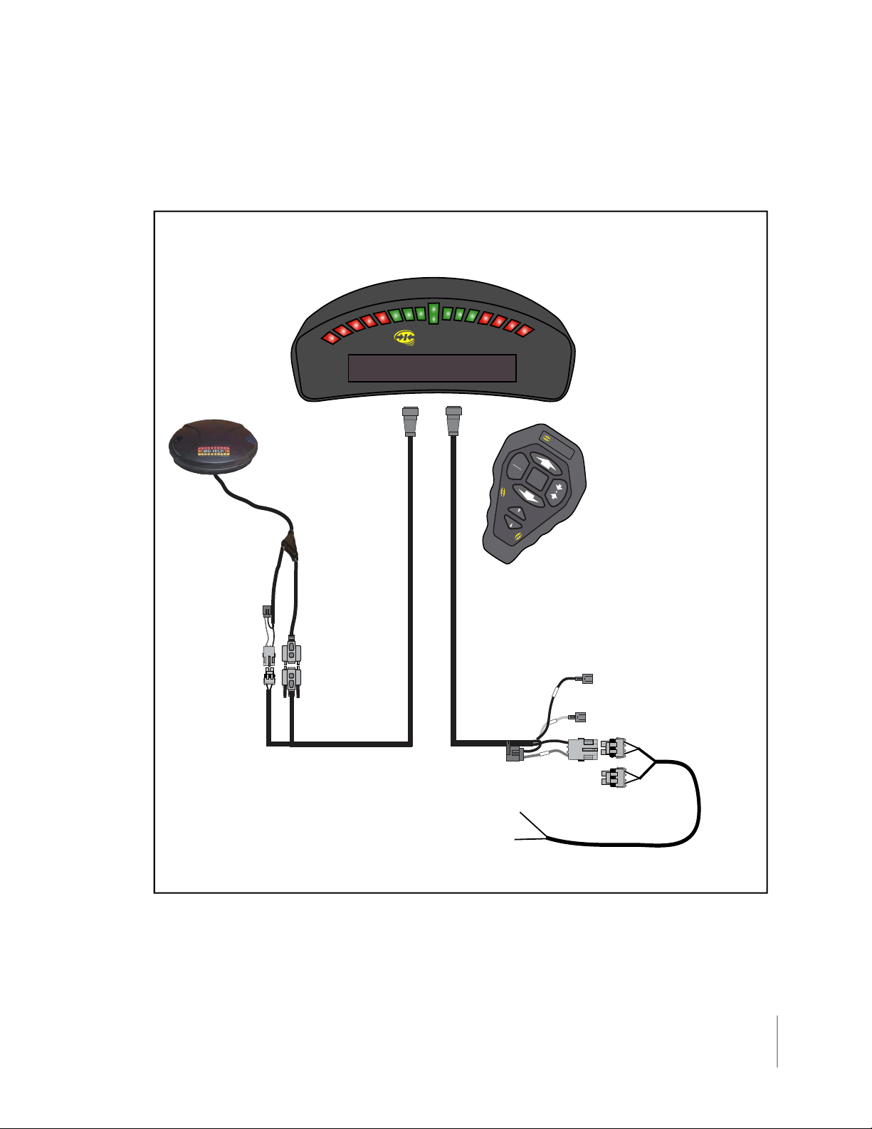
CenterLine with RX 400p DGPS Receiver
CenterLine Lightbar
CenterLine
M
UP
EN
U
ESC
D
OW
CenterLine
N
BRIGHT
DIM
CenterLine
Wireless Remote
CenterLine
CenterLine
Power lead
not used
Inline Fuse
11/2 Amp
+
Red
Flying Leads
RX 400p
GPS Receiver
& Antenna
RX 400p
RX 400p
Lat 5100.120 N+
Lon 1
M
ID-TECH
-
Blk
CenterLine
Power Cable
12'
se
en
H
igh
D
iffe
rentia
1
202.250 WH
Midwest Technologies, Inc.
A
ccu
ra
c
y
l G
P
S
R
ece
ive
r
ENTER
S
cc
A
t
a
B
5 Amp
To
CenterLine
Battery
GPS Data Cable
15'
Figure 9: CenterLine with RX 400p DGPS Receiver
Boom Sense +12V when booms are ON
Ignition Sense +12V when ignition is ON
Power Cable
12'
12
CenterLine
CenterLine Product Kits
Page 19

CenterLine
Software Version 1.05
CenterLine Setup
CenterLine Setup allows the configuring of the CenterLine product to best suit the current guidance and mapping needs. For the complete overview of the Setup process see "CenterLine Setup
Flow Diagram,“ on page 26. CenterLine Setup has three sub-menus: <GUIDANCE>, <LIGHT
BAR>, and <SYSTEM>. Each is described in detail below. Figure 10 shows the Setup flow.
The top level of CenterLine software has three menus to choose from: <START>, <SETUP>, and
<TOOLS>. To enter the setup menus, use Up or Down to scroll until <SETUP> is visible and press
Enter. When in Setup, scroll through the setup menu list, <GUIDANCE>, <LIGHTBAR>, and
<SYSTEM>, and select the desired setup menu by pressing Enter (See Figure 10).
-
Figure 10: CenterLine Setup Flow
CenterLine
CenterLine Setup
13
Page 20

CenterLine
Software Version 1.05
Guidance Setup
Guidance setup allows the set up of several parameters that pertain to guidance functionality. Currently there are four guidance settings (see Figure 11).
To access Guidance setup from the Setup menu, scroll until the text window displays <GUIDANCE>, and press Enter. Menu item <WIDTH> should be displayed in the text window. Use Up or
Down to scroll through the list of Guidance setup menu items.
Figure 11: Guidance Setup Flow
Setting Name Default Value
Width 30.0 feet (10 meters) Required
Antenna -Direction None Recommended
Antenna - Distance 0.0 ft. Recommended
Status Detect Off Optional
Alarm Off Recommended
Table 1: Guidance Menu Item Default Settings
The Guidance menu item <ANTENNA> is a sub-menu of Guidance. The <DIRECTION> and
<DISTANCE> menu items are listed under this Antenna sub-menu. The offset distance and direc
tion (See Figure 16) can be set from these menu items.
Change at 1st
Time Start Up
-
14
CenterLine
CenterLine Setup
Page 21

CenterLine
Software Version 1.05
Width
The Guidance setup parameter Width is the distance between guidelines. This width is typically
the vehicle implement width or spread area. Setting this width slightly smaller than the actual width
reduces skips. Setting this width slightly larger than the actual width reduces overlap.
To set the Width setting, go to <GUIDANCE>, scroll with Up or Down until <WIDTH> is displayed,
and press Enter. To increase the width press Up; to decrease the width press Down. Press Enter
when the desired width is set. The width value increments in 0.5 ft. intervals.
Figure 12: Setting the Guidance Width Value
Antenna
The Antenna sub-menu defines the spatial relationship between the GPS antenna and the vehicle
implement or delivery point. The GPS antenna should always be mounted along the vehicle center
line (See Figure 16). The two Antenna menu settings are Direction and Distance.
To enter the Antenna sub-menu, go to <GUIDANCE>, scroll until <ANTENNA> is displayed in the
text window, and press Enter. As mentioned there are two settings under Antenna: <DIRECTION>
and <DISTANCE>. The text window should display <DIRECTION>. Use Up or Down to move
between the <DIRECTION> and <DISTANCE> settings. Press Enter when the desired setting is
in the text window.
Figure 13: Accessing the Antenna Sub-Menu
Direction
The Direction setting is the direction from the GPS antenna to the swath or delivery point (See Figure 16).
To change the Direction setting, go to the Antenna sub-menu of Guidance setup, scroll until
<DIRECTION> is displayed in the text window, and press Enter. Using Up or Down scroll through
the direction pick list (See Figure 14) until the desired direction is displayed in the text window.
Press Enter to save the setting and return to the Guidance setup menu.
CenterLine
CenterLine Setup
15
Page 22

CenterLine
Software Version 1.05
DIRECTION BEHIND
Setting Description
Back The swath or delivery point is behind the GPS receiver on
Forward The swath or delivery point is in front of the GPS receiver on
FORWARD
Figure 14: Setting the Direction to Swath
the vehicle along the vehicle center line.
the vehicle along the vehicle center line.
Table 2: Direction to Swath Settings
Distance
The Distance setting is the distance from the GPS antenna to the swath or delivery location (See
Figure 16).
To set the Distance setting, go to the Antenna sub-menu of Guidance setup and press Enter.
Scroll until <DISTANCE> is displayed in the text window and press Enter. To increase the distance
press Up; to decrease the distance press Down. Press Enter when the desired distance is displayed.
Figure 15: Setting the Distance to the Swath
16
CenterLine
CenterLine Setup
Page 23

CenterLine
Software Version 1.05
Figure 16: Direction and Distance to Swath from DGPS Receiver
Status
The <STATUS> setting is used to auto detect implement status. When the status detect is properly
implemented, the CenterLine detects whether product delivery is on or off, based on the vehicles
product on/off switch. See —CenterLine Product Kits“ on page 9 - 12 for location of status connect
(boom sense) wiring.
To set the Status setting, go to Guidance setup, scroll with Up or Down until <STATUS> is displayed in the text window, and press Enter. Using Up or Down, scroll between the <ON> and
<OFF> settings until the desired setting is displayed in the text window. Press Enter to save the
setting and return to the Guidance setup menu.
Figure 17: Selecting the Status Setting
CenterLine
CenterLine Setup
17
Page 24

CenterLine
Software Version 1.05
Setting Description
OFF No Status Detect implemented. Default setting.
ON Status detect assumes a single swath centered on the vehi-
cle.
Table 3: Status Settings
Alarm
The <ALARM> setting, when set to ON, notifies the operator when entering a previously applied
area. The text window displays <APPLIED> when the implement swath is in a previously applied
area of the field.
To set the Alarm setting, go to Guidance setup, scroll until <ALARM> is displayed in the text window, and press enter. Using Up or Down, scroll between the <ON> and <OFF> settings until the
desired setting is displayed in the text window. Press Enter to save the setting and return to the
Guidance setup menu.
18
Figure 18: Setting the Alarm
Setting Description
Off No applied area detection.
On Applied area detection alarm.
Table 4: Status Detect Settings
CenterLine
CenterLine Setup
Page 25

CenterLine
Software Version 1.05
Lightbar Setup
Lightbar setup allows the selection of several parameters related to the lightbar. There are five
lightbar settings: Drive Sensitivity <SPACING>, Display Mode <MODE>, two selectable mes
sages: <TEXT 1> and <TEXT 2>, and <steer bar?> (See Figure 19 and Table 5).
-
Figure 19: The Lightbar Setup Flow
Setting Name Default Value
Spacing 1.5 ft. Optional
Mode Vehicle Optional
Text 1 X-Track Error Optional
Text 2 Applied Area Optional
Steer bar? No Optional
Table 5: Lightbar Menu Item Default Settings
Change at 1st
Time Start up
Spacing
The Spacing setting allows the selection of the distance that a single light on the lightbar LEDs represents.
To change the Spacing setting, go to Lightbar setup, scroll until <SPACING> is displayed in the
text window, and press Enter. To increase the spacing distance press UP; to decrease the spacing
press Down. Press the Enter key when the desired spacing is set. The Spacing range is 0.5 ft. to
9.5 ft., in 0.5‘ increments.
CenterLine
CenterLine Setup
19
Page 26

CenterLine
Software Version 1.05
Figure 20: Setting the LED Spacing
Mode
The Mode setting defines how the row of LEDs are interpreted. The center stack of Green LEDs
can represent either the current guideline or the vehicle (See Table 6).
To change the Mode setting, go to Lightbar setup, scroll until <MODE> is displayed in the text window, and press Enter. Using Up or Down, scroll through the Mode pick list until the desired setting
is displayed in the text window. Press the Enter key to save the setting and return to the <TEXT 1>
menu item.
Figure 21: Setting the Mode
Setting Description
Swath When Display Mode is set to Swath, the center stack of Green LEDs represents the cur-
rent guideline. In this mode, steer the vehicle to bring the moving LED back to center
Vehicle When Display Mode is set to Vehicle, the center stack of Green LEDs represents the
vehicle‘s position. In this mode, steer the vehicle to bring the center lights towards the
moving LED.
Table 6: Display Mode Settings
Text 1 and Text 2
The Text 1 and Text 2 settings allow you to select text messages from a set of predetermined guidance information messages. These messages are displayed in the lightbar text window for 15 seconds when first enabled, and cycled through during guidance operations. A maximum of two text
messages can be displayed.
20
CenterLine
CenterLine Setup
Page 27

CenterLine
Software Version 1.05
Text 1
To set the Text 1 setting, go to Lightbar setup, scroll using Up or Down until <TEXT 1> is displayed
in the text window, and press Enter. Using Up or Down scroll through the Text 1 pick list until the
desired message is displayed in the text window. Press Enter to save the setting and advance to
the <TEXT 2> menu item.
Figure 22: Selecting the Text 1 Message
Message Description
X-Track Displays the error (in distance) between the current guideline and the vehicle position.
Swath # Displays the current guideline number.
Ground Speed Displays the vehicle ground speed.
Area Applied Displays the amount of area covered, sprayed, or spread, in acres or hectares.
COG Course on Ground, displays the vehicle heading in degrees.
Off When Off is selected, no message is displayed in this message slot.
Table 7: Text 1 Options
Text 2
To set the Text 2 setting, go Lightbar setup, scroll using Up or Down until <TEXT 2> is displayed in
the text window, and press Enter. Using Up or Down scroll through the Text 2 pick list until the
desired message is displayed in the text window. Press Enter to save the setting and advance to
the STEER BAR? menu item.
CenterLine
CenterLine Setup
21
Page 28

CenterLine
Software Version 1.05
Figure 23: Selecting the Text 2 Message
Message Description
X-Track Displays the error (in distance) between the current guideline and the vehicle position.
Swath # Displays the current guideline number.
Ground Speed Displays the vehicle ground speed.
Area Applied Displays the amount of area covered, sprayed, or spread, in acres or hectares.
COG Course on Ground, displays the vehicle heading in degrees.
Off When Off is selected, no message is displayed in this message slot.
Table 8: Text 2 Message Options
Steer Bar
The Steer Bar setting determines how the LED steering display appears. The LEDs, representing
the vehicle track in relation to the current guideline, can be shown as a single LED or a solid bar
(See Table 9).
To change the Steer Bar setting, go to Lightbar setup, scroll until <STEER BAR?> is displayed in
the text window, and press Enter. Using Up or Down, scroll through the Steer Bar pick list until the
desired setting is displayed in the text window. Press the Enter key to save the setting and return
to the <SYSTEM> menu item.
22
CenterLine
CenterLine Setup
Page 29

CenterLine
Software Version 1.05
Figure 24: Setting the Steer Bar Option
Setting Description
Off
On
The LEDs, representing the vehicle track in relation to the current guideline, are
shown as a single LED.
The LEDs, representing the vehicle track in relation to the current guideline, are
shown as a solid bar.
Table 9: Steer Bar Settings
CenterLine
CenterLine Setup
23
Page 30

CenterLine
Software Version 1.05
System Setup
System setup allows the selection of settings that effect the entire CenterLine product. There are
only two settings: Units and Language (See Table 10).
Figure 25: System Setup
Setting Name Default Value
Unit US Optional
Language English Optional
Table 10: System Menu Item Default Settings
Change at 1st
Time Start Up
Units
System Units allows the selection of either US and Metric units (See Table 11).
To change the System Units, enter System Setup, scroll through the sub-menu list until <UNITS>
appears in the text window, and press Enter. Next scroll between the two units choices, <MET
RIC> and <US>. When the desired unit is displayed, press the Enter key. The software should
bring you back to <UNITS>.
Figure 26: Setting System Units
-
24
CenterLine
CenterLine Setup
Page 31

CenterLine
Software Version 1.05
Pick List Description
US All units are entered and displayed in Feet, Miles, and Acres. This is the default setting.
Metric All units are entered and displayed in Meters, Kilometers, and Hectares.
Table 11: The Unit Menu Item Settings
Language
CenterLine comes pre-loaded with several languages. To change the system language, enter System Setup, scroll through the sub-menu list until <LANGUAGE> appears in the text window, and
press Enter. Next scroll to the desired language using Up or Down. When the desired language is
displayed, press the Enter key. The software should return to <LANGUAGE>
Figure 27: Setting the System Language
CenterLine
CenterLine Setup
25
Page 32

CenterLine
Software Version 1.05
CenterLine Setup Flow Diagram
26
Figure 28: CenterLine Setup Flow Diagram
CenterLine
CenterLine Setup
Page 33

CenterLine
Software Version 1.05
Tools
The Tools menu is intended to provide some basic system diagnostics. Tools contains two diagnostic tools: Receiver and Lightbar (See Table 12).
To access Tools from the Setup menu, scroll until the text window displays <TOOLS>, and press
Enter. <RECEIVER> should be displayed in the text window. Use Up or Down to scroll through
the Tools menu.
Figure 29: The Tools Menu Flow
Menu Item Description
Receiver Checks the status of a connected GPS receiver.
Lightbar Tests the functionality of the CenterLine Lightbar LEDs and
text window.
Table 12: Tools Menu Items
Receiver
The Receiver diagnostic test queries the attached GPS receiver and returns its current configuration and status. This information is displayed in the text window on the lightbar.
To start the Receiver check, go to the Tools menu, scroll until <RECEIVER> is displayed in the text
window, and press Enter. The lightbar displays the diagnostic messages shown in Table 13.
CenterLine
Tools
27
Page 34

CenterLine
Software Version 1.05
Diagnostic Description
GPS Status If the lightbar is not receiving GPS data, the text window message
DGPS Status If the lightbar is receiving differentialy corrected GPS data, the text
NMEA Strings Returns the name of each NMEA string currently being received from
Data Rate Returns the current receiver data rate. This is typically 5 Hz. The rate
appears as <NO GPS>. If the lightbar is receiving GPS data but no
differentialy corrected GPS data, the text window message appears
as <GPS>.
window message appears as <DGPS>.
the receiver. As an example if the NMEA GPGGA string is being
received from the receiver then the text window displays <GPGGA>.
is displayed in the text window, e.g. <5 HZ> is displayed for the 5
Hertz data rate.
Table 13: Receiver Diagnostic Messages
Lightbar
The Lightbar diagnostic test initiates an illumination sequence of all of the LEDs and the text window, followed by a brightness control sequence. This allows the verification that all lights on the
CenterLine lightbar are working properly.
To start the Lightbar check, go to <TOOLS> and press Enter. Scroll with Up or Down until
<LIGHTBAR> is displayed in the text window and press Enter. The illumination sequence should
start. When test is completed the lightbar displays <END>.
28
CenterLine
Tools
Page 35

CenterLine
Software Version 1.05
CenterLine Real-Time Operation
Starting Real-time Operation
This section assumes that the setup section, —CenterLine Setup“ on page 13, has been read and
the CenterLine lightbar properly set up.
Start real-time operation by pressing Enter when <START> is displayed in the text window. The
<START> menu item is at the highest menu level. <START> can be easily reached from most
menu levels by scrolling to <TO START> and pressing Enter. This jumps to the <START> location
from anywhere in the menu structure (See Figure 28).
Figure 30 is a flow diagram of the CenterLine real-time operation and menu.
Figure 30: Real-Time Operation Flow Diagram
New? Resume?
When Enter has been pressed at the <START> location, a prompt to start a new field or resume
working in the current field appears. During real-time operation, CenterLine stores the vehicle‘s
trajectory data. This allows the operator to stop working in a field before finished and return at a
later time, continuing where they left off. Only the current field is stored.
Use Up or Down to scroll between the <NEW?> and <RESUME?> menu items. Selecting
<NEW?> clears the current field trajectory data and starts a new field in memory. Selecting
<RESUME?> retains the current field trajectory data and allows the start of guidance using the
existing data.
CenterLine
CenterLine Real-Time Operation
29
Page 36

CenterLine
Software Version 1.05
Real-time Operation
When <NEW?> or <RESUME?> is selected, real-time guidance begins. At this point, the GPS receiver
should be properly connected to the CenterLine lightbar and running.
page 9 - 12 for diagrams showing how the DGPS receiver should be connected.
ance mode is Straight-Line Guidance (See note below). The current guideline information is stored, along
with the field‘s trajectory data, and is lost when <NEW?> is selected and retained when <RESUME?> is
selected. Only information for a single guideline is stored. While in Headland mode, A and B points can be
marked for Straight-Line guidance.
NOTE: When the display shows <HEADLAND?>, it is asking if you want to switch to Headland mode
from Straight-Line. When the display shows <STRAIGHT?>, it is asking if you want to switch to
Straight-Line mode from Headland.
See —CenterLine Product Kits“ on
The default guid-
Real-time Menu
During real-time operation, a real-time menu (See Figure 30 on page 29) is available that allows
you to switch between guidance patterns, mark A and B points for straight-line guidance, start a
new A-B line, and exit. The real-time menu is accessed by pressing Up or Down during guidance
operation. When either of these keys is pressed, the guidance messages displayed in the text win
dow are replaced by the real-time menu (See Figure 30 on page 29). Use Up and Down to scroll
through the menu and press Enter to select an item. The real-time menu times out when 5 sec
onds have passed and no arrow keys have been pressed.
-
-
Apply On/Off
If no switchbox or boom sense cable is being used and the <GUIDANCE><STATUS> setting (See
—Status“ on page 17) is set to off, Apply On/Off information must be provided to the CenterLine sys
tem manually. To toggle the Apply On/Off status, scroll the real-time menu (See Figure 30 on
page 29) until <Apply on> or <Apply off> appears in the text window. Pressing Enter switches to
the status displayed.
NOTE: This does not turn the application on and off. It only notifies the CenterLine system
of the application status. <Apply on> and <Apply off> do not appear if <GUIDANCE><STATUS> is set to ON.
Marking A and B Locations
The Straight-line guidance mode requires a reference guideline to guide the vehicle along. Establishing a guideline involves marking two points along the reference guideline. To establish this reference guideline using the real-time menu, use Up or Down to scroll in the menu until <NEW
AB?> is displayed on the lightbar (See Figure 31), and press Enter. The menu item <MARK A> is
displayed. Mark the A location by pressing Enter when the desired location is passed. The menu
item <MARK B> is now displayed. To mark the B location, press Enter when the desired location is
passed. The reference guideline is now established and the lightbar should display <NEW AB?>.
-
30
CenterLine
CenterLine Real-Time Operation
Page 37

CenterLine
Software Version 1.05
NEW AB?
MARK A
Figure 31: The Mark A Mark B Sequence
MARK B NEW AB?
Switching between Guidance Modes
There may be situations where it is necessary to switch between guidance modes. Typically an
operator makes one or more passes around the field‘s headland area in the Headland guidance
mode. While driving the headlands, the operator may mark the A and B guideline points to be used
when switching modes. When the headlands are completed, the operator switches to the Straightline mode, and completes the field in a back and forth fashion.
To switch between guidance modes, scroll the real-time menu (See Figure 30 on page 29) until <HEADLAND?> or <STRAIGHT?> appears in the text window. When the desired mode is displayed, press Enter to
make it active.
Area Determination
The area of the current job or field is important information. CenterLine allows the determination of
the area of a field by driving the perimeter of the field. This can be conveniently done while driving
the first headland circuit in Headland mode.
To determine the area of a field, scroll the real-time menu until <AREA> is displayed (See
Figure 32 on page 32) and Press Enter. The lightbar displays <LEFT> or <RIGHT>. Using Up or
Down, select the side of the swath or implement that is closest to the field boundary. Press Enter
to start area calculation. The lightbar displays <!
close the boundary, scroll the real-time menu Figure 30 until <CLOSE> is displayed. Press Enter
to close the boundary and determine the area. Pressing <CLOSE> inserts a line between the starting location and the current location and uses that shape to determine area.
Map BND> or <Map BND #>. When ready to
The area is automatically determined when the vehicle drives within 4.5 meters (15 feet) of the
starting point.
The bounded area will be displayed on the lightbar as a part of the guidance message stream for
three minutes and when stopped in an —applied“ area.
If a bounded area has already been determined, the <VIEW> menu item is present. Pressing
Enter at the <VIEW> level displays the current bounded area value.
CenterLine
CenterLine Real-Time Operation
31
Page 38

CenterLine
Software Version 1.05
Figure 32: Area Determination Flow Diagram
32
CenterLine
CenterLine Real-Time Operation
Page 39

CenterLine
Software Version 1.05
Return to Point
CenterLine allows the operator to mark a point in the field to return to later in time. Typically the Return to Point feature is used to mark a location when stopping guidance and
wanting to start in the same location and in the same direction at a later time. This Return
to Point location is stored with the field‘s trajectory data, is lost when <NEW?> is selected,
and retained when <RESUME?> is selected.
There is a specific Return to Point key located on the wireless remote, see Figure 4. This key
works in toggle fashion; press it once to mark the point (the lightbar displays <Í©È>), press it
again to navigate back to the point. Stop the navigation process by pressing ESC. When Return
to Point is pressed again (third time) the old location is replaced with the current vehicle location.
While operating in the Return to Point mode, no active text messages are displayed except error
messages. If the vehicle enters an area that has already been applied, the display alternates
between the Return To Point distance and <Applied!>.
Exiting Real-time Operation
To exit guidance, press Esc or scroll with Up or Down in the real-time menu until <EXIT?> is displayed (Figure 33) in the text window and Press Enter. This stops real-time operation and returns
to the main menu.
Figure 33: Exit in Display
CenterLine
CenterLine Real-Time Operation
33
Page 40

CenterLine
Software Version 1.05
Headland Guidance Operation
This section describes how to operate CenterLine in the Headland guidance mode. The Headland
mode is used when the operator wants to drive several circuits around the field boundary and be
guided around all circuits that occur after the first. When several headland circuits have been com
pleted, the operator has the option of switching to the Straight-line mode. The Headland pattern is
also used when a user wants to do product application on terraced fields. In the Headland curved
guidance pattern, the operator can pull along side any previous applied swath and be guided par
allel to that swath by the X-Track guidance display.
To select the Headland guidance mode, scroll with Up or Down in the real-time menu until
<HEADLAND?> or <STRAIGHT?> is displayed on the lightbar. If <STRAIGHT?> is displayed then
Headland mode is already active. If <HEADLAND?> is displayed, press Enter. This switches the
guidance mode from Straight-Line to Headland.
NOTE: When the display shows <HEADLAND?>, it is asking if you want to switch to Headland mode
from Straight-Line. When the display shows <STRAIGHT?>, it is asking if you want to switch to
Straight-Line mode from Headland.
Reference Guideline
-
-
While operating in the Headland mode, the user has the option to mark the A and B points of the
reference guideline used in the Straight-line Guidance mode. This feature makes it easier for the
operator to Mark the A and B points while in Headland mode applying the headlands. It is always
best to mark the A and B points for the Straight-line mode while driving along a straight edge of a
field. For more detail on how to establish a reference guideline see —Marking A and B Locations“
on page 30.
The operator remains in the Headland mode until the guidance mode is changed using the realtime menu (see —Switching between Guidance Modes“ on page 31). The reference guideline is
only required for the Straight-line mode.
Headland Pattern Example
In this example the operator wants to apply two headland passes to the field and then switch to
Straight-line mode and apply the remainder of the field with straight-line parallel swath guidance.
After the first headland circuit the operator pulls parallel to the first circuit swath and begins apply
ing the second circuit while being guided parallel to the first circuit.
Figure 34 on page 35 shows the operator just finishing the first headland circuit. When the operator pulls along side the first headland circuit, curved guidance automatically starts. The operator is
now able to drive the second headland circuit parallel to the first circuit by following the guidance
information displayed on the lightbar.
Figure 35 on page 36 shows the operator being guided along side the initial headland circuit. The
lightbar automatically supplies guidance information. For more details on how to interpret curved
guidance information on the lightbar (See —Headland Mode Lightbar Graphics“ on page 38).
-
34
Figure 36 on page 36 shows the operator continuing to drive around the second headland circuit.
CenterLine
CenterLine Real-Time Operation
Page 41

CenterLine
Software Version 1.05
Figure 34: Completing the First Headland Circuit
CenterLine
CenterLine Real-Time Operation
35
Page 42

CenterLine
Software Version 1.05
Figure 35: Starting the Second Headland Pass
36
Figure 36: Continuing Around the Second Circuit.
CenterLine
CenterLine Real-Time Operation
Page 43

CenterLine
Software Version 1.05
Switching from Headland to Straight-line Mode
When the operator has completed the desired number of headland circuits, two circuits in our current example, the system is switched to Straight-line Guidance mode to apply the remainder of the
field in a straight back and forth fashion.
To switch from the Headland Pattern to another pattern ,see —Switching between Guidance Modes“
on page 31. If the operator is being guided along a curved path when the pattern is switched, the
lightbar no longer guides them along the curved path.
If a reference guideline was established while in the Headland Guidance mode, CenterLine automatically guides the vehicle along the closest parallel line as soon as the operator switches to the
Straight-line mode. If a reference guideline was not established during the Headland mode, then
the operator must mark the A B points. The lightbar displays the <MARK A> message, indicating
that no reference guideline exists.
Figure 37 shows the operator applying product in Straight-line mode. Because a reference guideline was established during the curved guidance process, the user can immediately start straightline guidance as soon as the guidance mode button is pressed.
Figure 37: Switched from Headland Mode to Straight-line Mode.
CenterLine Real-Time Operation
CenterLine
37
Page 44

CenterLine
Software Version 1.05
Figure 38: Completed Field Application
Figure 38 shows the completed field. Notice that there are several areas of the field where the
operator turned spray off to avoid double application on previously applied areas.
Headland Mode Lightbar Graphics
CenterLine‘s Headland mode guidance technique employs a lightbar text display graphic that aids
the operator when navigating parallel to a curved swath. The X-Track LED functionality that is
employed in Straight-line mode is also employed when driving in Headland mode.
A projected swath-path graphic is displayed in the text display area of the lightbar (See Figure 39).
This projected path is made up of four horizontal bars. The bottom bar represents the path closest
to the vehicle and the top bar is the path furthest away. The width of the bars decrease as they
move away from the vehicle to add a perspective view to the path ahead of the vehicle. The pro
jected distance of the first bar from the front of the vehicle is based on the vehicle speed. The lightbar in Figure 39 informs the user to drive straight, and there are no turns approaching. In Figure 40
the lightbar indicates the vehicle is approaching a turn to the right. The X-Track LEDs indicate that
the vehicle is slightly to the right of the guideline. Lightbar X-Track LEDs are set up in Swath mode.
Therefore the user must correct to the left to get back on line. The X-Track LEDs do not provide
any information relating to the curved path ahead of the vehicle, they only indicate where the vehi
cle is with respect to the guideline at the current vehicle location. The lightbar displays a —hollow“
path during the first headland pass to indicate that no guidance information is available yet (The
first pass must be completed before a parallel path can be established) (See Figure 41).
-
-
38
CenterLine
CenterLine Real-Time Operation
Page 45

CenterLine
Software Version 1.05
.
Figure 39: Curved Guidance Lightbar Graphics
Figure 40: Right-Hand Turn Ahead
CenterLine
TM
Figure 41: Hollow Path
CenterLine Real-Time Operation
CenterLine
39
Page 46

CenterLine
Software Version 1.05
Straight-line Guidance Operation
The Straight-line guidance mode provides vehicle guidance along straight lines, based on a reference guideline. The first step is to establish the reference guideline. This reference guideline is
used to calculate all other parallel guidelines. See —Apply On/Off“ on page 30 for more detail on
how to establish a reference guideline.
To mark the initial point A, begin driving along the first swath path. Typically this is along a straight
edge of a field boundary. While the vehicle is driving along the initial swath, the lightbar displays
<MARK A>. As the vehicle passes over the desired A location, press Enter to establish the guide
line point A.
The lightbar now displays <MARK B>. The next step is to establish guideline point B. To do this,
press Enter as the vehicle passes over the desired B location. This establishes the reference
guideline. The lightbar starts displaying X-Track guidance information as well as any user selected
messages defined in Lightbar setup (See See —Lightbar Setup“ on page 19). If the vehicle is too far
from the previously applied area to determine guidance information, a —Hollow“ path is displayed
(See Figure 41 on page 39).
When the reference guideline is established, the operator can begin driving straight-line guidance.
The CenterLine software detects which guideline is closest to the centerline of the vehicle and pro
vides guide information with respect to that line. As the vehicle moves across the field (Figure 42)
new guidelines, parallel to the reference guideline, are established based on the swath width value
entered in Guidance setup.
-
-
40
Figure 42: Working a Field in the Straight-line Guidance Mode
CenterLine
CenterLine Real-Time Operation
Page 47

CenterLine
Software Version 1.05
Applied Area Detection
CenterLine allows the detection of a previously applied area. To use applied area detection, the
Lightbar Setup - Alarm menu field must be set up prior to starting guidance. See —Alarm“ on page
18 of this User Guide for more details on how to set up this menu field.
Detecting A Previously Applied Area
Figure 43 shows how previously applied area detection works. As the vehicle enters a previously
applied area, the lightbar displays the message APPLIED, even if the application is turned off.
When the vehicle exits the previously applied area, the APPLIED message stops displaying.
Figure 43: Applied Area Detection in Headlands
Detecting Neighboring Swath
Applied area detection notifies the user when the vehicle crosses into a previously applied neighboring swath. Figure 44 shows an Applied Area Overlap example. The vehicle can overlap up to
25% of the Swath Width without being notified. Once the edge of the vehicle swath overlaps 25%
or more into a neighboring swath, the lightbar displays <APPLIED>.
CenterLine
CenterLine Real-Time Operation
41
Page 48

CenterLine
Software Version 1.05
Figure 44: Applied Area Overlap in Neighboring Swath
42
CenterLine
CenterLine Real-Time Operation
Page 49

CenterLine
Software Version 1.05
Lightbar Index
The CenterLine lightbar is capable of displaying a considerable amount of information to the user.
This information can be represented as text in the display window, illuminated cross track LEDs, or
a combination of text and lights. Information displayed on the lightbar depends on both user
defined settings and system warnings not controlled by the user. Table 14 describes each possible
lightbar state and possible information that could be displayed.
Lightbar State Description
Mark A: Displayed when establishing the guidance point
A of the reference guideline.
Mark B: Displayed when establishing the guidance point
B of the reference guideline.
Swath #: A user selected lightbar message. When not
on the initial guideline the first character is either L or R
for Left and Right of the initial guideline. The number
identifies how many lines left or right of the initial guideline.
X-Track Error: A user defined lightbar message. This
cross track error message is displayed when the vehicle
is on the guideline and there is no error.
X-Track Error: A user defined lightbar message. In this
example the operator should steer to the left 2.3 ft.
(Assuming that System Units is set to US and Lightbar
is set to Swath mode.)
Table 14: CenterLine Lightbar Index
CenterLine
Lightbar Index
43
Page 50

CenterLine
Software Version 1.05
Lightbar State Description
Ground Speed: A user defined lightbar message indicating the vehicle speed in Miles per Hour (MPH). System
Units is set to US.
Ground Speed: A user defined lightbar message indicating the vehicle speed in Kilometers per Hour (KPH).
System is Units set to Metric.
Course on Ground (COG): A user defined lightbar message indicating the vehicles heading in degrees 0 to
359. The example to the left indicates the vehicle‘s
course on the ground is due South (180 degrees).
Area Applied: A user defined lightbar message indicating the current amount of area applied in Acres. System
Units is set to US.
Area Applied: A user defined lightbar message indicating the current amount of area applied in Hectares. System Units is set to Metric.
Applied Area Detection: This message is displayed
when the vehicle is within a previously applied area.
Note that the Red stop light (far right light) is illuminated.
See —Applied Area Detection“ on page 41.
Table 14: CenterLine Lightbar Index
44
CenterLine
Lightbar Index
Page 51

CenterLine
Software Version 1.05
Lightbar State Description
Curved guidance information graphics. The four horizontal bars in the text display represent a perspective
view of the swath ahead of the vehicle. The bars skew
left or right to represent the curved path ahead.
Curved guidance information graphics. The path in the
text display represents a perspective view of the swath
ahead of the vehicle. The —hollow path“ indicates that
the vehicle is making the first headland pass and no
guidance information is available yet. The path skews
left or right to represent the curved path ahead.
Mapping Boundary: This message is displayed when
the user is mapping the field boundary. The arrow symbol on the left indicates the field boundary is on the left
side of the vehicle.
CenterLine
NO GPS
Mapping Boundary: This message is displayed when
the user is mapping the field boundary. The arrow symbol on the right indicates the field boundary is on the
right side of the vehicle.
System Warning: The message is displayed when there
is loss of differential GPS corrections. Guidance calculations are stopped until differential corrections resume.
System Warning: This message is displayed when there
is a complete loss of GPS signal to the GPS receiver or
Smartpad. Guidance calculations are stopped until
DGPS signal resumes.
Table 14: CenterLine Lightbar Index
CenterLine
Lightbar Index
45
Page 52

CenterLine
Software Version 1.05
Lightbar State Description
Lightbar Version Message: This message is displayed
when the user starts up CenterLine or runs the Lightbar
Test. This number varies and is based on lightbar ver
sion and model.
Table 14: CenterLine Lightbar Index
-
46
CenterLine
Lightbar Index
Page 53

Page 54

Midwest T echnologies
2864 Old Rochester Road
Springfield, IL 62703
 Loading...