

Page 1
MID-TECH
MIDWEST TECHNOLOGIES, INC.
ARC-6000
LIQUID/GRANULAR
APPLICATION CONTROL SYSTEM
USER GUIDE
PN - 98-05017
Rev . - 1
®
CE & STANDARD VERSION
Flow
RATE
.
Gal./
MID-TECH
MIDWEST TECHNOLOGIES, INC.
®
-Ac
ARC-6000
Automatic
Rate Controller
12345 67 89
BOOMS
ON OPERATE INC.
OFF SET- UP DEC.
%Rate
Product Vol.
Total Area
Field Area
Speed
Scan
Test
Speed
DISPLAY SELECTOR
Application Rate
Total Applied
Impl.Width
Distance
Prime
Midwest Technologies, Inc. of Illinois
Springfield, IL 62703
Page 2

ARC 6000
CHANGE LOG
98-05017
DATE: DATE CODE: PAGES AFFECTED: SW VERSION
05/15/00 00136 New Manual - CE Certified Console 2.03
Rev.- 1
Mid-T ech, Auto-Range, & T ASC ar e all registered trademarks of Midwest Technologies, Inc.
II
CE & STANDARDVERSION
Page 3

ARC 6000
98-05017
Rev.- 1
TABLE OF CONTENTS
CHANGE LOG ..................................................................................................................................................................... II
TABLE OF CONTENTS ...................................................................................................................................................... III
1.0. SWITCHES AND CONTROLS ................................................................................................................................... 1-1
1.1. POWER SWITCH ................................................................................................................................................ 1-1
1.2. MODE SELECTOR “OPERATE / SETUP” SWITCH ......................................................................................... 1-1
1.3. INC / DEC SWITCH ............................................................................................................................................ 1-1
1.4. DISPLAY SELECTOR......................................................................................................................................... 1-2
1.4.1. DISPLAY SELECTOR FUNCTIONS -OPERATE MODE (LIQUID APPLICATION) ............................... 1-2
1.4.2. DISPLAY SELECTOR FUNCTIONS -SET UP MODE (LIQUID APPLICATION) .................................... 1-3
1.4.3. DISPLAY SELECTOR FUNCTIONS-OPERATE MODE (GRANULAR APPLICATION) ........................ 1-4
1.4.4. DISPLAY SELECTOR FUNCTIONS-SET UP MODE (GRANULAR APPLICATION) ............................ 1-5
1.5. BOOM SECTION “ON/OFF” INDICATORS ...................................................................................................... 1-6
1.6. NOT USED ........................................................................................................................................................... 1-6
1.7.--STATUS SWITCH .............................................................................................................................................. 1-6
1.8. GROUND SPEED OVERRIDE (GSO) SWITCH .................................................................................................. 1-6
2.0. CALIBRATION AND SET UP .................................................................................................................................... 2-1
2.1. CHANGING THE APPLICATION PROGRAM ................................................................................................... 2-1
2.2. ENGLISH, METRIC OR METRISH UNITS ........................................................................................................ 2-1
2.2.1. UNITS FOR EACH POSITION (LIQUID APPLICATOR ONLY) .............................................................. 2-1
2.2.2. CHANGING UNITS (LIQUID APPLICATOR ONLY) .............................................................................. 2-2
2.3. SETTING APPLICATION RATE ......................................................................................................................... 2-2
2.4. SETTING THE % RATE CHANGE ..................................................................................................................... 2-2
2.5. SETTING BOOM WIDTHS ................................................................................................................................. 2-2
2.6. APPLICATION RATE SENSOR CALIBRATION ................................................................................................ 2-3
2.6.1. CALIBRATING THE LIQUID APPLICATION .......................................................................................... 2-3
2.6.1.1. DETERMINING THE FLOWMETER INITIAL CALIBRATION NUMBER ................................. 2-3
2.6.1.2. DETERMINING THE PRESSURE SENSOR INITIAL CALIBRATION NUMBER ....................... 2-4
2.6.1.3. PRESSURE SENSOR HIGH/LOW CALIBRATION ....................................................................... 2-4
2.6.1.4. FINE TUNING THE FLOW SENSOR CALIBRATION NUMBER ................................................. 2-5
2.6.1.5. SETTING THE CORRECTION FACTOR (Psi Mode) .................................................................... 2-7
2.6.2. CALIBRATING THE GRANULAR APPLICATION ................................................................................. 2-7
2.6.2.1. SETTING THE PRODUCT DENSITY............................................................................................. 2-7
2.6.2.2. CALCULATING THE INITIAL CALIBRATION NUMBER .......................................................... 2-7
2.6.2.3. RATE SENSOR CALIBRATION .................................................................................................... 2-8
2.7. DISTANCE CALIBRATION, GROUND SPEED SENSOR .................................................................................. 2-9
2.7.1. GENERAL CONSIDERATIONS AND INITIAL CALIBRATION NUMBERS ......................................... 2-9
2.7.2. DISTANCE CALIBRATION PROCEDURE .............................................................................................. 2-9
2.8. SETTING THE "HOLD/CLOSE" RESPONSE OF THE FLOW CONTROL VALVE ......................................... 2-10
2.8.1. STATUS SWITCH ................................................................................................................................... 2-10
2.8.2. ALL BOOMS "OFF" ................................................................................................................................ 2-10
2.9. SETTING THE GROUND SPEED OVERRIDE (GSO) VALUE. ......................................................................... 2-11
2.10. SETTING THE FIELD AREA ALARM ........................................................................................................... 2-11
2.11. PRODUCT VOLUME (FULL LOAD CAPACITY) ........................................................................................... 2-11
2.11.1. SETTING THE FULL LOAD CAPACITY ............................................................................................. 2-11
2.11.2. RECALLING THE FULL LOAD CAPACITY ....................................................................................... 2-12
2.11.3. SETTING A LOAD CAPACITY LESS THAN FULL LOAD ................................................................. 2-12
2.12. SETTING AUTO POWER DOWN TIME ......................................................................................................... 2-12
3.0. OPERATION ............................................................................................................................................................... 3-1
3.1. NORMAL START UP AND OPERATION ........................................................................................................... 3-1
3.2. CHANGING ACTIVE BOOM SECTIONS ........................................................................................................... 3-1
3.3. CHANGING APPLICATION RATE ..................................................................................................................... 3-2
3.4. PRIMING THE MAIN PUMP AND BOOM (LIQUID APPLICATION) .............................................................. 3-2
3.5. RAPID UNLOAD USING THE CONVEYOR (GRANULAR APPLICATION) ................................................... 3-3
3.6. GROUND SPEED OVERRIDE (GSO) .................................................................................................................. 3-3
III
CE & S
TANDARD VERSION
Page 4

98-05017
ARC 6000
Rev.- 1
4.0. MAINTENANCE ........................................................................................................................................................ 4-1
4.1. FLUSHING AND CLEANING ............................................................................................................................. 4-1
4.2. CONTROL CONSOLE ........................................................................................................................................ 4-1
4.3. GROUND SPEED SENSOR ................................................................................................................................. 4-1
4.4. FLOW SENSOR (LIQUID APPLICATION) ........................................................................................................ 4-2
4.5. CONVEYOR RATE SENSOR (GRANULAR APPLICATION) ........................................................................... 4-2
4.6. FLOW CONTROL VALVE (LIQUID APPLICATION) ........................................................................................ 4-2
4.7. WIRING HARNESS ............................................................................................................................................. 4-2
5.0. TROUBLE SHOOTING THE ARC SYSTEM ............................................................................................................. 5-1
5.1. ERROR MESSAGE “Err.”, INVALID SETUP PROCEDURE ............................................................................... 5-1
5.2. ERROR MESSAGE “Err E”, INVALID MEMORY .............................................................................................. 5-1
5.3. ERROR MESSAGE “Err 0”, INVALID CONSTANT SET TO ZERO .................................................................. 5-1
5.4. ERROR MESSAGE “Err-1, 2, 3, 4, & 5,” INVALID OPERATION ....................................................................... 5-2
5.4.1. ERROR MESSAGE “Err-1”....................................................................................................................... 5-2
5.4.2. ERROR MESSAGE “Err-2”....................................................................................................................... 5-2
5.4.3. ERROR MESSAGE “Err-3”....................................................................................................................... 5-2
5.4.4. ERROR MESSAGE “Err 4” ....................................................................................................................... 5-2
5.4.5. ERROR MESSAGE "Err 5" ........................................................................................................................ 5-3
5.5. ERROR MESSAGE “OFLO”, NUMERIC OVERFLOW ..................................................................................... 5-3
5.6. ERROR MESSAGE “Err L”, LOW VOLTAGE ..................................................................................................... 5-3
5.7. ERROR MESSAGES “Err C, n, hook (backward 7)”, INTERNAL DIAGNOSTICS............................................ 5-3
6.0. EMERGENCY OPERATIONS.................................................................................................................................... 6-1
6.1. GROUND SPEED SENSOR FAILURE ................................................................................................................ 6-1
6.2. FLOW CONTROL VALVE FAILURE (LIQUID APPLICATOR) .......................................................................... 6-1
6.3. FLOWMETER FAILURE (LIQUID APPLICATOR) ............................................................................................ 6-2
A-0. APPENDIX A - DRAWINGS .......................................................................................................................................A-1
A-1 ARC FLOW/PRESSURE BASED - WIRING DIAGRAM ....................................................................................A-2
A-2 ARC FLOW/PRESSURE BASED - PLUMBING DIAGRAM ..............................................................................A-3
A-3 ARC SERVICE FORM ........................................................................................................... .............................A-4
B.0. INTRODUCTION .......................................................................................................................................................B-2
B.1. HOW THE ARC CONTROLS APPLICATION RATE ......................................................................................... B-2
B.2. ARC SYSTEM COMPONENT PARTS ............................................................................................................... B-3
B.2.1. THE ARC SYSTEM CONTROL CONSOLE ...........................................................................................B-3
B.2.2. APPLICATION RATE SENSOR ...............................................................................................................B-3
B.2.2.1. LIQUID APPLICATION ..................................................................................................................B-3
B.2.2.2. LIQUID OR GRANULAR APPLICATION ..................................................................................... B-4
B.2.3. FLOW CONTROL VALVE ........................................................................................................................B-4
B.2.4. GROUND SPEED SENSOR ...................................................................................................................... B-4
B.2.5. BOOM INTERFACE .................................................................................................................................B-4
C.0. INSTALLATION .........................................................................................................................................................C-2
C.1. CONTROL CONSOLE INSTALLATION ............................................................................................................ C-2
C.1.1. CONSOLE MOUNTING ...........................................................................................................................C-2
C.1.2. CONSOLE CABLE ROUTING .................................................................................................................C-3
C.2. INSTALLING APPLICATION RATE SENSORS ................................................................................................C-4
C.2.1. FLOWMETER/PRESSURE SENSOR (FLOW SENSOR) INSTALLATION ............................................C-4
C.2.2. RATE SENSOR INSTALLATION .............................................................................................................C-5
C.3. FLOW CONTROL VALVE INSTALLATION ...................................................................................................... C-5
C.4. GROUND SPEED SENSOR INSTALLATION .................................................................................................... C-5
C.5. BOOM CONTROL SWITCHES AND INTERFACE ...........................................................................................C-6
C.5.1. BOOM INTERFACE CABLE ................................................................................................................... C-6
C.5.2. BOOM CONTROL SWITCHES AND INTERFACE .................................................................................C-6
SHADED TOPICS RELATE TO GRANULAR APPLICATION ONLY!
CE & STANDARD VERSION
IV
Page 5
ARC 6000
1.0. SWITCHES AND CONTROLS
98-05017
Rev.- 1
Flow
RATE
.
Gal./
MID-TECH
MIDWEST TECHNOLOGIES, INC.
4
ARC-6000
-Ac
¨
Automatic
Rate Controller
1
123456789
BOOMS
2
ON OPERATE INC.
OFF SET- UP DEC.
%Rate
Product Vol.
Total Area
Field Area Impl.Width
Speed
Scan
Test
Speed
DISPLAY SELECTOR
3
Application Rate
Total Applied
Distance
Prime
5
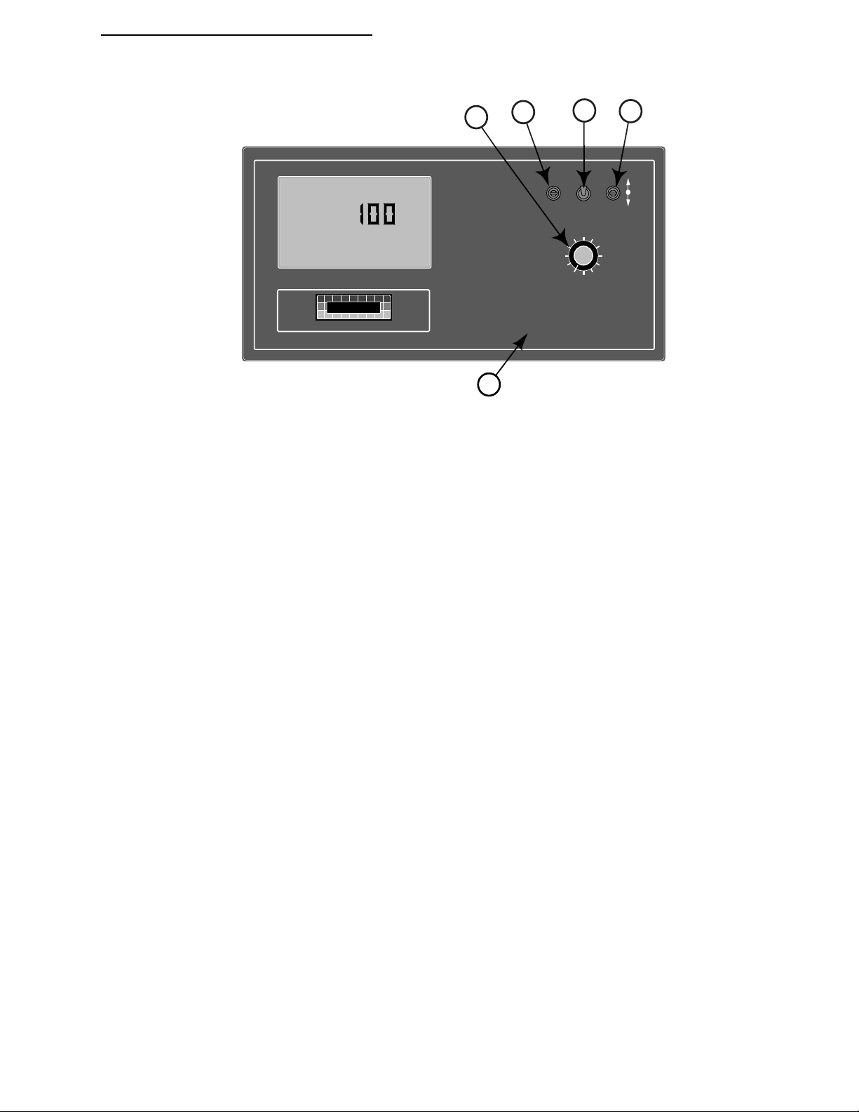
1.1. POWER SWITCH
The power switch controls power to the console. The console has an "Auto Power Down" feature which powers the console
off after an operator selectable time (default is 30 min) has elapsed. The console has a nonvolatile memory so it "remembers"
the constants and data previously entered, even if the power is removed.
NOTE: The “Auto Power Down Feature is only available on the CE version of the console (CE designation label on back of
console).
1.2. MODE SELECTOR “OPERATE / SETUP” SWITCH
The Mode Selector switch (upper right center) is used to switch between the OPERATE and SETUP modes of the control
console. When applying materials, this switch must be in the “OPERATE” position. The “SET- UP” position is used for
entering information into the console. In the SETUP Mode an “Err” message will appear if a position which can not be
programmed has been selected.
1.3. INC / DEC SWITCH
The INC/DEC switch (upper right corner) is used to change the values appearing in the display. The INC/DEC switch is
usable in either the OPERATE or SETUP Mode.
This switch is also used to zero the accumulated areas, distance, and total applied by selecting the desired display and
holding this switch in the “DEC” position until the display resets to zero, (approximately 3 sec.).
Use this switch to reset the full load condition while displaying Product Vol. in the operate mode. Holding the switch in the
"INC" position until the display shows the programmed, full load value.
1-1
CE & S
TANDARD VERSION
Page 6

98-05017
123456789
%Rate
DISPLAY SELECTOR
Speed
Field Area Impl.Width
Distance
Test
Speed
Prime
Total Applied
Application Rate
Scan
Total Area
Product Vol.
BOOMS
OFF SET- UP
ON OPERATE
Rev.- 1
1.4. DISPLAY SELECTOR
The Display Selector (right center) is used to select and display the various console functions.
OPERATE
ARC 6000
Flow
RATE
.
Gal./
Product Vol.
Total Area
MID-TECH
Field Area Impl.Width
MIDWEST TECHNOLOGIES, INC.
Speed
DISPLAY SELECTOR
¨
Scan
-Ac
%Rate
Test
Speed
ARC-6000
Automatic
Rate Controller
Application Rate
Total Applied
Distance
Prime
ON OPERATE INC.
SET- UP
OFF SET- UP DEC.
%Rate
Product Vol.
Application Rate
Total Area
Field Area Impl.Width
Speed
Scan
Prime
Test
Speed
DISPLAY SELECTOR
123456789
BOOMS
Total Applied
Distance
1.4.1. DISPLAY SELECTOR FUNCTIONS -OPERATE MODE (LIQUID APPLICATION)
SPEED: The current vehicle speed in tenths of a Mile per Hour.
FIELD AREA: Accumulated Area, in hundredths of an Acre.*
TOTAL AREA: Accumulated Area, in Acres.*
PRODUCT V OL.: Amount of product aboard the vehicle. Resets to a pre-programmed, full load by holding the INC
switch up with ground speed zero. Ground speed zero also allows setting any value using the INC/DEC switch. Value
counts down as the product is applied, an alarm sounds with ten percent left aboard.**
% RATE: The percent of programmed application rate at which the product is being applied. This percentage can be
changed up or down a preset amount by operating the INC/DEC switch.***
APPLICATION RATE: The desired application rate can be set with the INC/DEC switch when the ground speed is zero
or all booms are OFF.** Once application has commenced, and metered discharge is established, the actual measured
application rate will be displayed here. Also used to set the controlvalve to manual operation.
TOTAL APPLIED: The actual volume applied, as measured by the flowmeter or pressure sensor.*
IMPL. WIDTH: The active boom width in tenths of Feet. Depends on the actual boom sections selected “ON”.
DISTANCE: The accumulated distance in Feet, Miles after 5,280 Ft.*
PRIME: This position is used to lock the control valve open during main pump priming on a liquid system. Initially the
display will show a series of five dashes. Hold INC switch up for three seconds to lock the control valve fully open. The
display will read OPEN. Switching away from PRIME will cause the control valve to drive CLOSED. When operating
in the pressure based (Psi) mode, the current boom pressure is displayed here.
TEST SPEED: The speed the console will use for stationary tests of the sprayer. Use the INC/DEC switch to change this
value.**
SCAN: The display will scan SPEED, FIELD AREA, PRODUCT VOLUME, APPLICATION RATE, TOTAL APPLIED,
and, if in pressure based mode, BOOM PRESSURE. The display will hold at each position for approximately two
seconds before automatically cycling to the next.
NOTES: * Totals can be zeroed in this mode.
** Values are programmable in this mode.
CE & STANDARD VERSION
***Values changeable by a % increase or decrease.
1-2
Page 7

ARC 6000
12345678
%Rate
DISPLAY SELECTOR
Speed
Field Area Impl.Width
Distance
Test
Speed
Prime
Total Applied
Application Rate
Scan
Total Area
Product Vol.
BOOMS
OFF SET- UP
ON OPERATE
98-05017
Rev.- 1
OPERATE
Flow
RATE
Gal./
Product Vol.
Total Area
MID-TECH
Field Area Impl.Width
MIDWEST TECHNOLOGIES, INC.
Speed
ARC-6000
Automatic
-Ac
Rate Controller
.
%Rate
Test
Speed
Application Rate
Total Applied
Distance
Prime
¨
Scan
ON OPERATE INC.
SET- UP
OFF SET- UP DEC.
%Rate
Application Rate
Product Vol.
Total Area
Field Area Impl.Width
Speed
Prime
Scan
Test
Speed
DISPLAY SELECTOR
123456789
BOOMS
Total Applied
Distance
DISPLAY SELECTOR
1.4.2. DISPLAY SELECTOR FUNCTIONS -SET UP MODE (LIQUID APPLICATION)
SPEED: Ground Speed Override Value (GSO), in tenths of a MPH. Use the INC/DEC switch to change.**
FIELD AREA: Select area alarm. For example; if the alarm is set (using the INC/DEC switch) to 10.00, then
the display will flash and the console will beep when each increment of ten acres is reached. The display will
react for about three seconds and then stop until the next increment is reached.**
TOTAL AREA: Err, No function in the SETUP mode.
PRODUCT V OLUME: Use the INC/DEC switch to set the full tank capacity of the vehicle.**
% RATE: The percent of change in the application rate for each actuation of the INC/DEC switch, when
application operations are underway. Use the INC/DEC switch to change.**
APPLICATION RATE: A pressure sensor correction factor which is used when applying products with a specific
gravity different from that of water (see chart on page 2-7). The correction factor is only visible in Psi mode. Reads ERR
when in STnrd L or rEFLO L modes. Use the INC/DEC switch to change. Maximum is 1.50, minimum is 0.50**
TOTAL APPLIED: This is the pressure sensor or flowmeter calibration number. Use the INC/DEC switch to
change. Note: Must have all booms ON when in the REFLOW Mode.**
WIDTH: Individual boom section widths in inches. The display will cycle through the individual boom sections in
order, unless a particular boom switch is activated while the boom master switch is ON. Use the INC/DEC switch to
change.**
DISTANCE: The current Distance Calibration Number. Use the INC/DEC switch to change.**
PRIME: Holding the INC switch up for over ten seconds establishes LIQUID operation, either STnrd (standard), PSi
(Pressure) or rEFLO (reflow). Holding the DEC switch down for over ten seconds establishes GRANULAR operation,
either STnrd (standard) or SPLit (split drive). Current setting is shown in the display, Pump L is liquid, Pump C is
granular.
TEST SPEED: The current Test Speed in tenths of a Miles per Hour. Use the INC/DEC switch to change this value.**
SCAN: Err, No function in the SETUP mode.
NOTES: * Totals can be zeroed in this mode.
** Values are programmable in this mode.
***Values changeable by a % increase or decrease.
1-3
CE & S
TANDARD VERSION
Page 8

98-05017
123456789
%Rate
DISPLAY SELECTOR
Speed
Field Area Impl.Width
Distance
Test
Speed
Prime
Total Applied
Application Rate
Scan
Total Area
Product Vol.
BOOMS
OFF SET- UP
ON OPERATE
Rev.- 1
ARC 6000
OPERATE
Flow
RATE
.
Gal./
Product Vol.
Total Area
MID-TECH
Field Area Impl.Width
MIDWEST TECHNOLOGIES, INC.
Speed
DISPLAY SELECTOR
¨
Scan
-Ac
%Rate
Test
Speed
ARC-6000
Automatic
Rate Controller
Application Rate
Total Applied
Distance
Prime
ON OPERATE INC.
SET- UP
OFF SET- UP DEC.
%Rate
Application Rate
Product Vol.
Speed
Scan
Test
Speed
DISPLAY SELECTOR
Prime
Total Applied
Distance
Total Area
Field Area Impl.Width
123456789
BOOMS
1.4.3. DISPLAY SELECTOR FUNCTIONS-OPERATE MODE (GRANULAR APPLICATION)
SPEED: The current vehicle speed in tenths of a Mile per Hour.
FIELD AREA: Accumulated Area, in hundredths of an Acre.*
TOTAL AREA: Accumulated Area, in tenths of an Acre.*
PRODUCT V OL.: Amount of product aboard the vehicle. Resets to a pre-programmed, full load by holding theINC
switch up with ground speed zero. Also allows setting any value using the INC/DEC switch. Value counts down as the
product is applied, an alarm sounds with ten percent left aboard.**
% RATE: The percent of programmed application rate at which the product is being applied. This percentage can be
changed up or down a preset amount by operating the INC/DEC switch.***
APPLICATION RATE: The desired application rate can be set with the INC/DEC switch when the ground speed is zero
or all booms are OFF.** Once application has commenced, and metered discharge is established, the actual measured
application rate will be displayed here. Also used to set the control valve to manual operation.
TOTAL APPLIED: The actual volume applied, as measured by the rate sensor. Rounds to tons after accumulating
19,999 pounds.*
IMPL. WIDTH: The active boom width in tenths of Feet. Depends on the actual boom sections selected “ON”.
DISTANCE: The accumulated distance in Feet, Miles after 5,280 Ft. (Accumulates only when selector switch is in this
position or when applying product)*
PRIME: This position is used to lock the control valve open. It can be used in a granular application to unload the
vehicle at its maximum discharge rate. Initially the display will show a series of five dashes. Hold INC switch up for
three seconds to lock the control valve fully open. The display will read OPEN. Switching away or toggling the DEC
switch will cause the valve to CLOSE.
TEST SPEED: The speed the console will use for stationary tests of the sprayer. Use the INC/DEC switch to change this
value.**
SCAN: The display will scan SPEED, FIELD AREA, PRODUCT VOLUME, APPLICATION RATE and TOTAL
APPLIED. The display will hold at each position for approximately two seconds before automatically cycling to the
next.
NOTES: * Totals can be zeroed in this mode.
CE & STANDARD VERSION
** Values are programmable in this mode.
***Values changeable by a % increase or decrease.
1-4
Page 9

ARC 6000
12345678
%Rate
DISPLAY SELECTOR
Speed
Field Area Impl.Width
Distance
Test
Speed
Prime
Total Applied
Application Rate
Scan
Total Area
Product Vol.
BOOMS
OFF SET- UP
ON OPERATE
98-05017
Rev.- 1
OPERATE
Flow
RATE
.
Gal./
Product Vol.
Total Area
MID-TECH
Field Area Impl.Width
MIDWEST TECHNOLOGIES, INC.
Speed
¨
Scan
-Ac
%Rate
Test
Speed
ARC-6000
Automatic
Rate Controller
Application Rate
Total Applied
Distance
Prime
ON OPERATE INC.
SET- UP
OFF SET- UP DEC.
%Rate
Application Rate
Product Vol.
Speed
Scan
Test
Speed
DISPLAY SELECTOR
Total Applied
Prime
Total Area
Field Area Impl.Width
123456789
BOOMS
Distance
DISPLAY SELECTOR
1.4.4. DISPLAY SELECTOR FUNCTIONS-SET UP MODE (GRANULAR APPLICATION)
SPEED: Ground Speed Override (GSO) Value, in tenths of a MPH, INC/DEC switch changes.**
FIELD AREA: Select area alarm. For example; if the alarm is set (using the INC/DEC switch) to 10.00, then the display
will flash "FIELD AREA" and the console will beep when each increment of ten acres is reached. The display will
react for about three seconds and then stop until the next increment is reached.**
TOTAL AREA: Err, No function in the SETUP mode.
PRODUCT V OLUME: Use the INC/DEC switch to set the full load capacity of the vehicle.**
% RATE: The percent of change in the application rate for each actuation of the INC/DEC switch, when application
operations are underway. Use the INC/DEC switch to change the value.**
APPLICATION RATE: Product density. The default value is 65.0. Use the INC/DEC switch to set the measured
product density.**
TOTAL APPLIED: This is the rate sensor calibration number. Calculate and use the number of sensor pulses per cubic
foot as the initial setting. Use the INC/DEC switch to change. Must have all booms ON when in the SPLIT Drive
Mode**
WIDTH: Individual boom section widths in inches. The display will cycle through the individual boom sections in
order, unless a particular boom solenoid switch is activated. Use the INC/DEC switch to change.**
DISTANCE: The current Distance Calibration Number. Use the INC/DEC switch to change.**
PRIME: Holding the DEC switch down for over ten seconds establishes GRANULAR operation, either STnrd (standard)
or SPLit (split drive). Holding the INC switch up for over ten seconds establishes LIQUID operation, either STnrd
(standard) or rEFLO (reflow). Current setting is shown in the display, Pump L is liquid, Pump C is granular.
TEST SPEED: The current Test Speed in tenths of a Mile per Hour. Use the INC/DEC switch to change this value.**
SCAN: Err, No function in the SETUP mode.
** Values are programmable in this mode.
***Values changeable by a % increase or decrease.
NOTES: * Totals can be zeroed in this mode.
1-5
CE & S
TANDARD VERSION
Page 10

98-05017
ARC 6000
Rev.- 1
1.5. BOOM SECTION “ON/OFF” INDICATORS
The boom section on/off indicators (lower right, labeled “BOOMS”), indicate which boom sections have been selected by
the operator. When a boom has been selected, its indicator will light. Boom position number 1 is to the left. There is a
maximum of nine boom sections available.
1.6. NOT USED
1.7.--STATUS SWITCH
A status switch can be used to override the ARC control. The switch must present a positive voltage (+12.0 VDC) status on
the green (or white) wire of the Boom Interface Cable. So long as this condition is present, the control console will operate
normally. If the voltage is interrupted, the control console will automatically stop controlling. At the same time, the control
console will either "HOLD" or "CLOSE" the control valve, depending on the response selected by the operator. (See Section
2.9.1).
The intent of this feature is to allow the operator to control the operation of the control valve through the normal operation of
the vehicle. The Status switch input may be used to sense the "ON"/"OFF" condition of the main vehicle pump switch, a
separate Status switch, or, an external switch may sense an implement "UP"/"DOWN" condition. The Status switch can
often be used to lessen the operator's work load.
1.8. GROUND SPEED OVERRIDE (GSO) SWITCH
If the ARC system was purchased with an optional MID-TECH boom switch box, the Ground Speed Override switch is
already installed. If a MID-TECH switch box is not used to control the booms, an optional externally mounted Ground
Speed Override switch can be used to temporarily operate the sprayer (or spreader) using a pre-selected Minimum "(GSO)
Speed" rather than the actual speed registered by the Ground Speed Sensor. The override feature is used to bring the
applicator on line quickly when starting from a dead stop or to maintain an adequate application pattern when the vehicle is
maneuvering at very low ground speeds. It can also be used to allow the operator to flush or empty the vehicle from the cab,
while stopped.
The control console operates normally so long as the Ground Speed Override switch condition is open (OFF). Whenever the
Override switch is closed (ON) and the actual ground speed is less than "GSO Speed", the control console automatically
selects the "GSO Speed" value to control application rate. As soon as the switch reverts to its normally open (OFF) condition, or the actual ground speed increases above the preset "GSO Speed", the control console will adjust the rate on the basis
of the actual ground speed.
CAUTION: Controlling application rates based on "GSO Speed" is not as accurate as using the actual ground speed.
When Ground Speed Override is being used and the true ground speed is less than the "GSO Speed", the console will
sound a warning beep and the display will flash a "Too Slow" message to warn the operator of over application.
CE & STANDARD VERSION
1-6
Page 11

ARC 6000
2.0. CALIBRATION AND SET UP
NOTE: PLEASE READ THROUGH THE FOLLOWING SECTIONS COMPLETELY BEFORE YOU BEGIN
CALIBRATION!
The control console needs to be calibrated and programmed with certain information before it is ready to be used. First, the console
needs to be programmed with the specific details of your applicator (i.e. Application Rates, Boom Widths, Test Speed, etc.). Next,
the rate sensor (flowmeter) and ground speed sensors both need to be calibrated. The calibration and set up processes are not
difficult, however; they must be followed precisely in order to get the maximum available accuracy out of the system.
First, BE SURE THE CONSOLE IS SELECTED TO THE APPLICATION PROGRAM YOU WANT. The Choices are;
Liquid Pressure, Liquid standard, Liquid reflow, Granular standard, and Granular split drive.
2.1. CHANGING THE APPLICATION PROGRAM
To view the program currently selected, set the Mode switch to "SETUP" and the Display Selector to "PRIME".
Pump L PSi is LIQUID PRESSURE application (normal pressure based spraying)
Pump L STnrd is STANDARD LIQUID application (normal flow based spraying)
Pump L rEFLO is LIQUID REFLOW application (for use on some European sprayers)
Pump C STnrd is standard GRANULAR application (single conveyor spreaders)
Pump C SPLit is GRANULAR SPLIT DRIVE application (dual conveyor spreaders, air delivery spreaders)
98-0501
Rev.- 1
To change programs, hold the INC switch up to set LIQUID and cycle between standard, reflow, and pressure. Hold the DEC
switch down to set GRANULAR and cycle between standard and split drive. The application remaining in the display when the
INC/DEC switch is released is the program selected. If you have a question about which application to use, check with your
supplier or call MID-TECH Customer Service.
2.2. ENGLISH, METRIC OR METRISH UNITS
When operating as a LIQUID applicator the control console is capable of displaying three separate units of measure, English,
Metric and Metrish. Metrish is the same as Metric, except area is measured in Acres, thus the term Metrish. Operating as a
granular applicator, the display is limited to English units of measurement.
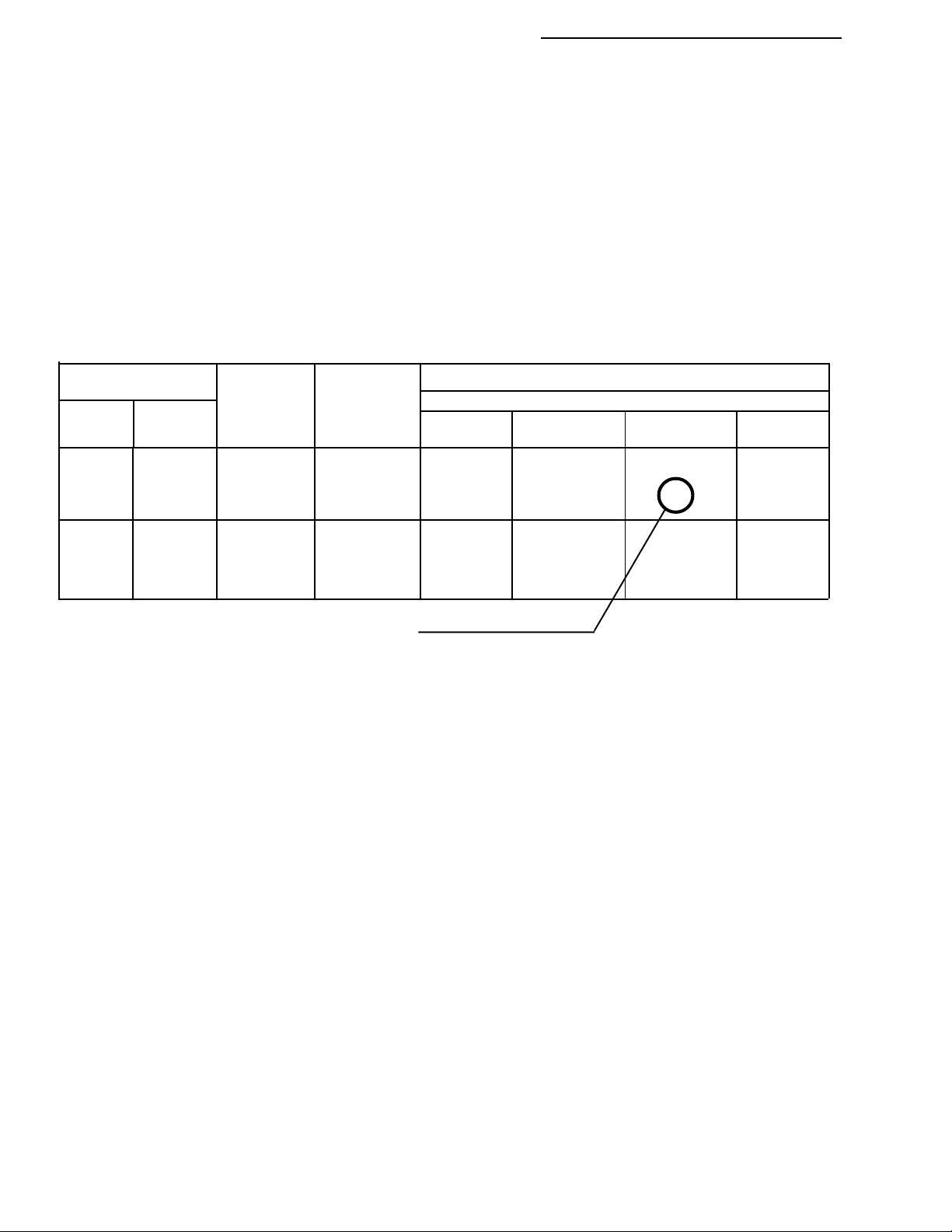
2.2.1. UNITS FOR EACH POSITION (LIQUID APPLICATOR ONLY)
POSITION ENGLISH (US) METRIC METRISH
Speed Miles/Hour (MPH) Kilometers/Hour (KPH) Kilometers/Hour(KPH)
Field Area Acres ( Ac) Hectares ( Ha) Acres ( Ac)
Total Area Acres ( Ac Hectares ( Ha) Acres ( Ac
Product Vol. Gallons (Gal.) Liters Liters
Appl. Rate Gallons/Acre(Gal.-Ac) Liters/Hectare (Liters-Ha) Liters/Acre (Liters-Ac)
Total Applied Gallons (Gal.) Liters Liters
Impl. Width Inches - Feet (In., Ft.) Meters Meters
Distance Feet - Miles (Ft.)* Meters - Kilometers* Meters - Kilometers*
Test Speed Miles/Hour (MPH) Kilometers/Hour (KPH) Kilometers/Hour(KPH)
* No units displayed after roll over of feet to miles or meters to kilometers
2-1
CE & STANDARD VERSION
Page 12

98-05017
ARC 6000
Rev.- 1
2.2.2. CHANGING UNITS (LIQUID APPLICATOR ONLY)
To change units, set the Mode switch to “OPERATE” and the Display Selector to “SPEED”. The current speed units will be
displayed. Holding the INC/DEC switch up or down (see chart) until the display changes (approximately 5 sec.) will set the units
accordingly.
UNITS INC./DEC. Switch
English to Metric DOWN
Metric to English DOWN
English to Metrish UP
Metrish to English DOWN
NOTE: Metric to Metrish is not allowed. Convert to English first and then to Metrish.
2.3. SETTING APPLICATION RATE
The ARC system is designed to maintain a constant, pre-selected application rate. In order for the control console to do this, the
operator must enter the desired application rate.
A. Set the console switches to the following positions:
Power ON
Mode Selector OPERATE (Application rate is set in the Operate Mode!!!)
Display Selector APPLICATION RATE
Ground Speed ZERO
All Booms OFF
The display will show the current application rate.
B. Use the INC/DEC switch to set the value displayed to the desired rate.
C. Setting the APPLICATION RATE to 0.0 will shut off the flow control function.
2.4. SETTING THE % RATE CHANGE
This feature allows the operator to change the application rate “On The Go”. Application rate is changed with a simple
actuation of the INC/DEC switch. The amount of change each switch actuation makes is proportional to the value programmed into this position, (e.g. 20 =20% change in the target rate). For example, if the liquid application rate is set at 10.0
gallons per acre, a single actuation of the INC switch will cause the valve to control flow at the rate of 12.0 gallons per acre
(10.0 + 20% = 12.0).
A. Set the console switches to the following positions:
Power ON
Mode Selector SETUP
Display Selector % RATE
The display will show the current % change value.
B. Use the INC/DEC switch to set this number to the desired % change value.
2.5. SETTING BOOM WIDTHS
The MIDWEST TECHNOLOGIES control console is designed to automatically compensate for changes in the swath width,
caused by turning on or off boom sections. For the console to automatically respond to changes in swath width, it needs to
know the size of each boom section. Use the following procedure to set boom section widths.
CE & STANDARD VERSION
2-2
Page 13

ARC 6000
A. Set the console to the following positions;
Power ON
Mode Selector SET- UP
Display Selector IMPL. WIDTH
All Boom Solenoid Switches (external) OFF
The display will cycle through each boom position (1 through 9) and display its current width in inches.
B. As each boom position appears on the display, use the INC/DEC switch to set the display to the number of inches
covered by that boom. Repeat for each section.
NOTE: Individual boom widths are entered in inches. For example; for a liquid boom with 7 nozzles on
30" spacings, enter 180 for that boom. There is no need to convert to feet, the control console does that
automatically when it is switched back to the OPERATE MODE.
C. Set all unused boom sections to a width of zero “0” inches. This will insure that an accidental boom switch ON will not
affect the control console.
D. The boom width is now set. Turn all boom switches to the ON position and return to the OPERATE Mode, the new
total boom width will be displayed in feet. If this does not agree with your total applicator width, check the individual
boom widths, (steps B and C).
98-0501
Rev.- 1
2.6. APPLICATION RATE SENSOR CALIBRATION
The control console must be calibrated for the flowmeter, pressure sensor, or rate sensor being used. The calibration number
required by the control console is the actual number of electrical pulses per unit volume generated by the sensor, or, for the pressure
sensor, the gallons per acre rating of the nozzles being used. If you have any doubts as to the accuracy of the flow sensor
readings, a field calibration/catch test should be performed using the actual product solution. (see section 2.6.1.4)
2.6.1. CALIBRATING THE LIQUID APPLICATION
Verify that the correct application program has been selected (see section 2.1.)!
If in the Psi mode, check the correction factor. It should be set to 1.0 during the calibration routine. To check the correction
factor, set the Display Selector to APPLICATION RATE, set the Mode Selector switch to SETUP. Use the INC/DEC
switch to set the correction factor if necessary.
2.6.1.1. DETERMINING THE FLOWMETER INITIAL CALIBRATION NUMBER
FLOWMETERS are calibrated for water at the factory. This number is accurate enough for most applications. However, the
actual flow characteristics may differ due to plumbing or other factors.
Standard Flowmeters
SIZE SUPPLIER CAL.# SIZE SUPPLIER CAL.#
.75 inch (Mid-Tech) 396.9 3.00 inch (Mid-Tech) 5.0
1.00 inch (Mid-Tech) 153.1
1.50 inch (Mid-Tech) 38.8 1.25 inch (Raven) 75.0*
2.00 inch (Mid-Tech) 23.8 3.00 inch (Raven) 16.4*
Mid-Tech Rapid Check Flowmeters
SIZE RANGE CAL# SIZE RANGE CAL#
1.00 inch 0.75 - 5 gpm 3200 1.50 inch 2.5 - 25 gpm 612.4
1.00 inch 2.5 - 16 gpm 800 1.50 inch 2.6 - 53 gpm 361.9
2.00 inch 20.0 - 195 gpm 94.5
* Raven flow meters, use the factory calibration number divided by 10. All other flowmeters use the manufacturers'
supplied information regarding the pulses per gallon (usually provided on a tag on the flowmeter).
2-3
CE & STANDARD VERSION
Page 14
98-05017
ARC 6000
Rev.- 1
Once the initial calibration number has been entered into the console, proceed to section 2.6.1.4 to fine tune the flowmeter
for maximum accuracy.
2.6.1.2. DETERMINING THE PRESSURE SENSOR INITIAL CALIBRATION NUMBER
The Pressure Sensor Calibration Number can be found by determining the "Gallons per Acre" rating for the type of nozzles
being used. First find the chart that represents the nozzle series you will use and the nozzle spacing of your boom. Then find
the nozzle size needed for the range of speeds and the rate needed. When the nozzle has been selected find the column of
nozzle ratings in "Gallons per Acre" at 10 MPH. Then, on the left of the chart, find the horizontal line representing the
ratings at 30 PSI. Where the column and row intersect you will find the "Gallons per Acre" rating of your nozzles at 10
MPH and 30 PSI. This is the value to enter into the console as the pressure sensor Cal. #. For example, in the following chart,
for a floodjet K-SS10 nozzle, the row for 30 PSI and column for 10 MPH cross at 26.0 gallons per acre, the pressure sensor
cal. number for this particular nozzle.
NOTE: We recommend that these tests be done using water, and only after neutralizing the tank and system.
Gallons per AcreType
Liquid Capacity 40" Spacing
Floodjet
Tip No.
TK-SS10
4
TK-SS15
Floodjet Pressure in 6 8 10 12
Nozzle in PSI GPM MPH MPH MPH MPH
10 1.0 25.0 16.6 14.9 12.4
K-SS10 20 1.4 35.0 26.0 21.0 17.5
30
40
10 1.5 37.0 28.0 22.0 18.6
K-SS15 20 2.1 53.0 39.0 32.0 26.0
30 2.6 64.0 48.0 39.0 32.0
40 3.0 74.0 56.0 45.0 37.0
1.7
2.0
43.0 32.0 26.0 21.0
50.0 37.0 30.0 25.0
Use this number as the cal. number in this example.
Use the following procedure to enter the flow sensor calibration number.
A. Set the console to the following positions;
Power ON
Mode Selector SET- UP
Master Switch OFF
Display Selector TOTAL APPLIED
B. Use the INC/DEC switch to select the desired flow sensor calibration number.
2.6.1.3. PRESSURE SENSOR HIGH/LOW CALIBRATION
The pressure sensor's low and high values must be set to match the readings from your pressure gauge following the procedure below.
SETTING THE LOW SIDE:
A. Set the console to the following positions;
Power Switch ON
Setup/Operate Switch OPERATE
Display Selector Switch PRIME
Master Switch ON
At least one Boom Switch ON (to release any trapped pressure)
(May have to remove nozzle if it has a check valve)
Ground speed 0 (zero)
GSO Switch OFF
CE & STANDARD VERSION
2-4
Page 15

ARC 6000
B. Hold INC/DEC switch to DEC until console reads PSi 0
Note: A display reading of "PSi - -" indicates that the pressure sensor is not connected. A reading of "PSi - 0" indicates a reading of less than 0 PSI. This suggests that the sensor may need to be recalibrated to 0 pressure.
SETTING THE HIGH SIDE:
A. Set the console to the following positions;
Power Switch ON
Setup/Operate Switch OPERATE
Display Selector Switch PRIME
Master Switch ON
Supply Pump ON
Ground speed 0 (zero)
B. Hold the INC/DEC switch to INC for about 3 seconds. The display will read "OPEN". Release the INC switch. Push
the INC switch again and hold it for about 3 seconds. The display will read "PSi xxx". The xxx is a pressure. The INC/
DEC switch can now be used to adjust the pressure reading on the console to match the reading on the pressure gauge. If
no switch changes are detected after 3 seconds, the console will read "OPEN" again. Actuating the DEC switch when the
console reads "OPEN" will cause the console to read "CLOSE" and the valve will close.
2.6.1.4. FINE TUNING THE FLOW SENSOR CALIBRATION NUMBER
98-0501
Rev.- 1
NOTE: We recommend that these tests be done using water, and only after neutralizing the tank and system.
Once the initial calibration number has been determined and entered into the console, a calibration run should be made to adjust
the number for maximum accuracy. The hardest part of the calibration procedure will be accurately measuring the actual discharge
of large volumes of liquid. The more accurately the discharge is measured, the more accurate the calibration will be. Since each
operator's facilities are different, it is not possible to prescribe a standard method of measuring discharge. Operators have
successfully performed the task using a second, calibrated flow meter, using a truck scale and calculating volumes based on weight
and density of the liquid discharged, and by discharging into a marked, calibrated tank.
It is necessary to pump and measure at least 100 gallons, and as much as 300 gallons, depending on the accuracy required. For
example: if the actual measurement is accurate to within 3 gallons, using 300 gallons will yield an accuracy of 1 %.
If only 100 gallons are pumped and measured, the calibration can be off as much as 3%. The better the measurement accuracy
of actual discharge and the more material pumped, the more accurate will be the resulting calibration.
A method similar to the following is recommended.
1. If using Psi mode, enter the appropriate Correction Factor for the material that you will be using for the test (Not
applicable for rEFLO or STnrd applications) (see section 2.4.1).
2. Turn the Mode Switch to "OPERATE", the Display Selector to "APPLICATION RATE". Enter the desired
application rate.
3. Verify that the boom switches are "OFF", select the "SETUP" mode; rotate the display selector switch to
"TOTAL APPLIED".
4. For Psi mode applications, the current pressure sensor calibration number will be displayed. Verify that it is the
recommended initial calibration number for the nozzles installed in the system. For rEFLO or STnrd applications,
the flowmeter calibration number will be displayed (rEFLO mode requires all booms be on to view cal. #.) Use the
INC/DEC switch to adjust as necessary.
5. Select "OPERATE" with the mode selector switch. Hold the DEC switch down for three to five seconds to zero
the accumulated gallons.
6. Make sure there is enough liquid in the main tank to do the test. Weigh the sprayer and load of water. Position
the sprayer in an appropriate area to do the calibration test.
2-5
CE & STANDARD VERSION
Page 16

98-05017
Rev.- 1
7. Start the main carrier pump, Rotate the display selector switch to "TEST SPEED". Turn "ON" the Master Switch
and the Boom Switches. The sprayer will start to spray. Allow the sprayer to discharge until the desired amount has
been pumped. Turn "OFF" the Master Switch.
8. Weigh the sprayer again and calculate the amount of water discharged.
9. Turn the display selector switch to "TOTAL APPLIED" and select "OPERATE" with the Mode Switch. If the
total shown on the console agrees with the total amount actually discharged, no further action is necessary. The
pressure sensor, or flowmeter, is now calibrated.
10. If the indicated volume pumped does not agree with the actual volume pumped, calculate a new calibration # as
follows:
PRESSURE SENSOR: New Cal. # =(MEASURED AMOUNT / INDICATED AMOUNT) X Old Cal. #
If the measured amount is more than the indicated amount, the new cal# should be larger.
If the measured amount is less than the indicated amount, the new cal# should be smaller.
FLOW METER: New Cal. # =(INDICATED AMOUNT/ MEASURED AMOUNT) X Old Cal.#
If the measured amount is more than the indicated amount, the new cal. # should be smaller.
If the measured amount is less than the indicated amount, the new cal# should be larger.
10. Set the mode selector to "SETUP" and select "TOTAL APPLIED". Change the cal. # using the INC/DEC
switch. Return the mode selector to "OPERATE". The amount displayed will now match the amount measured.
The flow sensor is now calibrated.
ARC 6000
10a. An alternate method, of correcting the cal. #, at this point, is to switch back and forth, between "OPERATE/
TOTAL APPLIED AND SETUP/ TOTAL APPLIED", changing the cal. # until the Total Applied display, in
operate mode, equals the amount actually dispensed.
11. Write this number down for future reference. This will be the number to use for these specific conditions
(material and applicator configuration).
Another Method of fine tuning the sensor cal. # would be to weigh the sprayer with a full tank of water, zero out the "Total Applied",
set the GSO speed to 10 MPH, and start spraying while watching the "Total Applied" accumulate. When the "Total Applied" has
reached at least 100 gallons, re-weigh the sprayer and determine the actual amount applied as compared to that indicated by the
console. Use the method described in step 9 and 10 above to correct the Cal. #.
Fine tuning of the calibration number can also be done based on field experience.
L Psi (bAr) Mode - Material left over - Adj. Cal. # down slightly
- Short of material - Ad1j. Cal. # up slightly
L STnrd and - Material left over - Adj. Cal. # up slightly
rEFLO Modes - Short of material - Adj. Cal. # down slightly
CE & STANDARD VERSION
2-6
Page 17

ARC 6000
98-0501
Rev.- 1
2.6.1.5. SETTING THE CORRECTION FACTOR (Psi Mode)
If you will be spraying water solutions, the correction factor should be set to 1.00. If you will be spraying a solution with a specific
gravity different than that of water, adjust the correction factor according to the following chart.
Weight of Solution Correction Factor
7.0 lbs/gal .92
8.0 lbs/gal .98
8.34 lbs/gal - Water 1.00
9.0 lbs/gal 1.04
10.0 lbs/gal 1.10
10.65 lbs/gal - 28% Nitrogen 1.13
11.0 lbs/gal 1.15
12.0 lbs/gal 1.20
14.0 lbs/gal 1.30
To enter the correction factor, go to APPLICATION RATE and SETUP mode. Use the
INC/DEC switch to adjust the correction factor.
2.6.2. CALIBRATING THE GRANULAR APPLICATION
Check to be sure the correct application program has been selected (see section 2.1.)!
2.6.2.1. SETTING THE PRODUCT DENSITY
ARC needs to know the product density in order to control the application rate. IF PRODUCT DENSITY IS NOT CORRECT, THE APPLICATION RATE WILL NOT BE CORRECT. Product density is entered as pounds per cubic foot.
Product density should be measured and entered with each load of product.
A. Set the console switches to the following positions:
Power ON
Mode Selector SETUP
Display Selector APPLICATION RATE
The display will show the current product density.
B. Use the INC/DEC switch to set the display to the desired density.
2.6.2.2. CALCULATING THE INITIAL CALIBRATION NUMBER
It is necessary to enter a spreader constant in ARC to ensure an accurate output from the conveyor. The spreader constant is
the number of sensor pulses per cubic foot of material discharged. The constant is different for different gate height settings
on adjustable spreaders. Constants relating to particular gate height settings should be calibrated and recorded for the
spreader.
Calculation of the initial spreader constant requires the following information; 1) Gate height (H) and width (W), in inches,
2) Number of sensor pulses for each revolution of the spreader rate sensor (P), 3) The distance the conveyor moves during
one revolution of the spreader rate sensor (D), in inches.
Calculate the initial spreader constant as follows:
Where; Ft
3
is the volume discharged during each revolution of the spreader rate sensor, in Cubic Feet.
r
Continue as follows:
3
P / Ft
= Initial Calibration Number (Spreader Constant)
r
( D x W x H ) / 1728 = Ft
2-7
3
r
CE & STANDARD VERSION
Page 18

98-05017
ARC 6000
Rev.- 1
Enter this calibration number into the console memory using the procedure that follows.
A. Set the console switches to the following positions:
Power ON
Mode Selector SETUP
Display Selector TOTAL APPLIED
Boom Switches ON (If Split Drive mode is active)
The current Spreader Constant will be displayed.
B. Use the INC/DEC switch to set the display to the calculated Spreader Constant. Remember, the number
cannot be changed when the console is in the Split Drive mode, unless all booms are turned on.
2.6.2.3. RATE SENSOR CALIBRATION
The accuracy of the Spreader Constant should be verified, and adjusted as necessary. The following procedure is suggested
as a relatively simple means of testing the calibration of the spreader constant. BE SURE THE PROPER PRODUCT
DENSITY HAS BEEN ENTERED BEFORE PERFORMING THE CALIBRATION OR THE RESULTS WILL BE
INACCURATE.
A. Set the console switches to the following positions:
Power ON
Mode Selector SETUP
Display Selector TOTAL APPLIED
Boom Switches ON (If Split Drive mode is active)
The display will show the Current Spreader Constant. Record this number for reference.
Turn all booms OFF.
B. Load the vehicle with product of known density. Be sure the density is properly entered in the ARC (Section 2.6.2.1.).
C. Weigh the truck and load and record this weight. Back up to a location where you can safely unload the material
through the conveyor. Be sure the hydraulics are engaged so that there is pressure to the conveyor control valve.
D. Switch the Mode Selector to OPERATE and hold the DEC switch down until the display resets to zero.
E. Rotate the Display Selector to TEST SPEED (be sure an appropriate speed is entered using the INC/DEC switch).
Turn the booms ON and the conveyor will begin to discharge.
F. Discharge enough material to get an accurate measurement but be careful to keep the conveyor running full. As an
example: if the truck scale reads in 20 lb. increments, at least 1000 lbs. must be discharged to be able to calibrate within
1%.
G. When sufficient material has been discharged, turn the booms OFF and rotate the Display Selector to TO T AL AP-
PLIED. ARC displays the Indicated Amount discharged by the conveyor in lbs (or tons over 20,000 lbs.).
H. Weigh the truck and load (be sure the driver's weight is included if he was on the truck when it was weighed the first
time). The difference between the starting weight and the ending weight is the Actual Amount discharged by the
conveyor. (This procedure assumes fuel use is minimal during the test).
I. To adjust the Spreader Constant, use the following formula:
(INDICATED AMOUNT / MEASURED AMOUNT) X CURRENT SPREADER CONSTANT = NEW SPREADER CONSTANT
If the weight read from the console is greater than the weight actually measured, the calibration number will increase.
J. Put the Mode Selector to SETUP and use the INC/DEC switch to change the Spreader Constant. (REMEMBER, IF
SPLIT DRIVE IS ACTIVE, THE BOOM SWITCHES MUST BE ON.) Turn the booms OFF and switch the Mode
CE & STANDARD VERSION
2-8
Page 19

ARC 6000
Selector switch back to OPERATE, the corrected Indicated Amount will be displayed. If this number does not match
the Actual Amount, check the calculation.
NOTE: Write down the spreader constants for different gate settings. Use these numbers whenever that gate setting is
selected.
If it is not convenient to conduct an actual test, field experience will allow fine tuning of the spreader constant. If the
spreader is applying too much, decrease the spreader constant by the same percentage as the over application. If too
little material is being applied, increase the spreader constant by the same percentage as the under application.
2.7. DISTANCE CALIBRATION, GROUND SPEED SENSOR
2.7.1. GENERAL CONSIDERATIONS AND INITIAL CALIBRATION NUMBERS
The control console must be calibrated for the ground speed sensor installation to ensure accurate application rates. The procedure
involves physically measuring an accurate distance along a road or field, driving the vehicle through that distance, and
mathematically comparing the distance computed by the control console to the actual measured distance. If the two distances
compare exactly, no change is necessary. If the distances do not compare exactly, the console can be calibrated by changing the
distance calibration number a proportionate amount. Following the recommended procedure below will ensure accuracy of
operation.
The distance calibration must be periodically checked. This is especially important if the sensor has come loose or been
repositioned, or if the tires have been changed.
98-0501
Rev.- 1
Use the following initial calibration settings to get started. For the radar this number will be pretty close. For the wheel speed
sensor and the speedometer sensor the adjustment to this initial calibration number may be very large, depending on the
configuration of the vehicle. It is important to field calibrate the distance sensor to insure optimum accuracy!
RADAR - 1000 WHEEL SENSOR - 3500 SPEEDOMETER SENSOR - 3500
A. Set the control console switches to the following settings:
Power ON
Mode Selector SETUP
Display Selector DISTANCE
The display will now show the current distance calibration value.
B. Use the INC/DEC switch to select the initial distance calibration value suggested.
You are now ready to perform the distance calibration.
2.7.2. DISTANCE CALIBRATION PROCEDURE
The following procedure is recommended by MIDWEST TECHNOLOGIES for establishing an accurate distance calibration.
NOTE: All boom switches should remain OFF during the entire procedure.
1. Fill the vehicle 1/2 full of material, to approximate actual load conditions. This will minimize the effect on the radar
mounting angle and/or actual working diameter of the tires as the load empties.
2. Measure out a known distance of 400 ft. or more in a field or roadway. The longer the distance, the more accurately the
test can be performed, but keep it in even hundreds of feet and the calculations will be easier.
3. Drive the vehicle to the starting point of the distance range and stop.
4. Turn the Display Selector to the DISTANCE position and the Mode Select switch to the SET- UP mode. The console
will display the current Distance Calibration Number. Record this number for future reference. As an example, assume
this number is 1000.
2-9
CE & STANDARD VERSION
Page 20

98-05017
ARC 6000
Rev.- 1
5. Return the Mode Select switch to the OPERATE position and check to see that the accumulated distance is set at zero.
If not, reset it to zero using the INC/DEC switch.
6. Start driving. Drive the vehicle at a speed of between five and ten miles per hour. Distance measurements will start to
accumulate in the display.
7. Stop the vehicle at the end marker. The display will show the accumulated distance. Compare this distance to the actual
measured distance, to determine how much of a correction is necessary. For example, if an accumulated distance of 396
Ft. is shown after driving over a 400 foot range, the error in the distance calibration is 1.0%.
8. Calculate the new Distance Calibration Number using the following formula:
(Measured distance/Accumulated distance) x Old DC# = New DC#
Example: (400 / 396) x 1000 = 1010, the New DC#
NOTE: The same procedure is used, regardless of the type of distance sensor .
RECORD THE DISTANCE CALIBRATION NUMBER HERE: ______________
2.8. SETTING THE "HOLD/CLOSE" RESPONSE OF THE FLOW CONTROL VALVE
The operator can select a "Hold" or "Close" response of the Flow Control valve to both the Status switch and to an "All Booms
OFF" condition. These responses are independent of each other, allowing the operator to select a "Hold" condition for one and
a "Close" for the other. Careful consideration should be given to both conditions and the response selected for your application.
2.8.1. STATUS SWITCH
When the "Hold" condition is selected, turning off the Status switch will hold the Flow Control valve in its current position. The
valve will not close even though the vehicle speed may drop to zero. Then, when the Status switch is turned on the Flow Control
valve is already open and product flow is instantaneous. This response assumes that some other device has stopped the product
flow.
When the "Close" condition is selected, turning off the Status switch will automatically cause the Flow Control valve to close.
This response would be preferred when it is necessary to use the Flow Control valve to stop the product flow.
To select the desired response:
A. Set the console switches to the following positions:
Power ON
Mode Selector OPERATE
Display Selector TOTAL APPLIED
Boom Switches OFF
B. Hold the INC switch up to display the current response selected.
C. Continuing to hold the INC switch up causes the display to cycle between "Hold" and "Close" at about three second
intervals. The last option appearing in the display when the INC switch is released will be the response selected.
2.8.2. ALL BOOMS "OFF"
When the "Hold" condition is selected, all booms OFF will hold the Flow Control valve in its current position. The valve will
not close even though the vehicle speed may drop to zero. Then, when the booms are selected ON again the Flow Control valve
is already open and product flow is instantaneous.
When the "Close" condition is selected, all booms OFF will automatically cause the Flow Control valve to close. This response
would be preferred when it is necessary to use the Flow Control valve to positively stop the product flow.
CE & STANDARD VERSION
2-10
Page 21

ARC 6000
To select the desired response:
A. Set the console switches to the following positions:
Power ON
Mode Selector OPERATE
Display Selector IMPL WIDTH
Boom Switches OFF
B. Hold the INC switch up to display the current response selected.
C. Continuing to hold the INC switch up causes the display to cycle between "Hold" and "Close" at about three second
intervals. The last option appearing in the display when the INC switch is released will be the response selected.
2.9. SETTING THE GROUND SPEED OVERRIDE (GSO) VALUE.
With the Display Selector set to the Speed position in the SETUP Mode, the console will display the current Ground Speed
Override value. This value can be changed using the INC/DEC switch. If you intend to use this feature, set the value to the
minimum Ground Speed you want to control to when the GSO switch is activated. This should be the lowest speed at which the
sprayer will operate smoothly and provide a good nozzle pattern. If you do not intend to use this feature, set this value to zero (0.0).
CAUTION: This feature causes the product to be applied at a rate consistent with the GSO speed, not the true ground
speed. Serious over application can occur, if not used properly.
98-0501
Rev.- 1
2.10. SETTING THE FIELD AREA ALARM
Use the field area alarm to alert the operator as he accumulates specific area amounts. The console will flash and beep as each
area increment is accumulated.
An operator may use this feature to remind him to check his load to be certain it is disappearing at the correct rate. He also could
use this feature to double check acreage estimates.
A. Make sure all booms are OFF. Set the control console to the following switch settings:
Power ON
Mode Selector SETUP
Display Selector FIELD AREA
The display will now show the current selected acreage increments.
B. Use the INC/DEC switch to set the desired acreage increments.
C. Return the Mode Selector switch to OPERATE to apply.
2.11. PRODUCT VOLUME (FULL LOAD CAPACITY)
2.11.1. SETTING THE FULL LOAD CAPACITY
The full load capacity of the vehicle can be preset in the control console so that it can be recalled as the vehicle is reloaded.
A. Make sure all booms are OFF. Set the control console to the following switch settings:
Power ON
Mode Selector SETUP
Display Selector PRODUCT VOL.
The display will now show the current selected full load capacity.
2-11
CE & STANDARD VERSION
Page 22

98-05017
ARC 6000
Rev.- 1
B. Use the INC/DEC switch to set the desired full load capacity.
C. Return the Mode Selector switch to OPERATE to apply.
2.11.2. RECALLING THE FULL LOAD CAPACITY
Whenever PRODUCT VOL. is displayed in the OPERATE mode, the full load capacity of the vehicle can be recalled by
holding the INC switch up for at least three seconds.
2.11.3. SETTING A LOAD CAPACITY LESS THAN FULL LOAD
If a full load is not taken aboard the vehicle, the actual amount loaded can be set when PRODUCT VOL. is displayed in the
OPERATE mode by holding the DEC switch down (about three seconds) until the Product Vol. values start to decrease. Once
the numbers start to change, they can be set up or down using the INC/DEC switch until the actual load is displayed. Switching
out of the PRODUCT VOL. display will bring the control console back to normal operation.
2.12. SETTING AUTO POWER DOWN TIME
The console has an "Auto Power Down" feature which powers the console off after an operator selectable period (default is
30 min) has elapsed. If no input is received from the speed sensor or any console switch during this time the APD feature is
activated. The APD time can be set from 15 to 60 minutes. Selecting a period less than 15 minutes disables the APD feature.
A. Use the following switch settings to adjust the Auto Power down time:
Power OFF
Mode selector SET-UP
Display selector % Rate
Hold the INC switch UP while turning the power on
The display will show the current Auto Power Down time.
B. Select the desired time using the INC/DEC switch.
C. Exit this set-up mode by moving the Display Selector to another position, the Mode Selector to OPERATE, or
turning the console OFF and back ON.
NOTE: The “Auto Power Down Feature is only available on the CE version of the console (CE designation label on back of
console). If you have the standard console model always turn the console power off when not in use to prevent unnecessary
drain on the battery.
CE & STANDARD VERSION
2-12
Page 23

ARC 6000
3.0. OPERATION
Under normal operating conditions, the MIDWEST TECHNOLOGIES control system is automatic. The system will perform
precisely, according to the information and directions it has received from the operator. It is important to verify that the
control console has the proper instructions before beginning operations each day. It is also important that the switches are
operated properly to ensure accurate application of chemical.
3.1. NORMAL START UP AND OPERATION
A. CONSTANTS: With all external boom switches in the OFF position, check to ensure the proper constants are still
entered in the console. Refer to section 2.0. of this manual to review the procedure for entering these constants. It is a
good idea to write the constants down in a convenient location.
B. APPLICATION RATES: With all Boom switches in the OFF position and the Mode Selector switch in the OPERATE
position, review the application rate by selecting APPLICATION RATE on the display selector.
C. ACCUMULATED AREA: The accumulated acres can be reset to zero by selecting FIELD AREA or TO T AL AREA,
in the OPERATE mode, and holding the INC/DEC switch down until the display resets to zero. The area accumulators
can be zeroed independently to keep track of two separate areas.
D. ACCUMULATED VOLUME: Accumulated volume can be reset to zero by selecting TOTAL APPLIED while in the
OPERATE mode and using the DEC switch to reset. PRODUCT V OL. (the count down register) can be set for the
load aboard by using the procedures in section 2.12.
98-05017
Rev.- 1
E. Now, the Control System is ready to begin automated application. Set the Mode Selector switch to the OPERATE
position. Select an appropriate display using the Display Selector, “SCAN” for example.
F. Be sure the pumps and/or hydraulics are fully engaged.
G. Drive toward the area to be covered. Reaching that position, continue to drive in the direction of the first swath and
turn the desired Boom switches ON. The ARC will control application.
H. Upon reaching the end of the swath, turn the Boom switches to the OFF position to temporarily stop application.
When the vehicle has been turned and is ready to start applying on the next swath, turn the Boom switches to the ON
position and the controlled application will resume.
3.2. CHANGING ACTIVE BOOM SECTIONS
The active boom sections can be changed at any time by turning the appropriate Boom switches ON or OFF. The control
system, will automatically adjust flow rate as individual boom sections are activated or deactivated. When all the Boom
Section switches are OFF, the application will be stopped. This allows the operator to select active boom sections “On The
Go”, while depending on the control system to apply the proper rate on the area being covered.
3-1
CE & STANDARD VERSION
Page 24

98-05017
Rev.- 1
3.3. CHANGING APPLICATION RATE
The operator has chosen a desired application rate and entered this value into the control console using the procedure
outlined in Section 2.2. of this manual. Anticipating the need to increase or decrease the application rate, the operator has
also established a % rate change using the procedure described in Section 2.4. of the manual. As an example, assume the
control console has been set up to apply 10.0 gallons per acre with a % rate change set at 20%
During normal spraying, the control console will maintain the application rate at 10.0 gallons per acre. However, let’s
suppose the operator is spraying an aqueous fertilizer. A soil type change in the middle of the field requires a 40% higher
application in order to reach desired fertility levels. As the sprayer crosses into the new soil type, the operator selects %
RATE with the Display Selector. The display will show the percentage of the programmed application rate, in this case
100%. Pushing the INC/DEC switch up twice will increase the application rate by 2 X 20% or 40%. The display will show
140. The flow control valve will open until the flowmeter records 14.0 gallons per acre. None of the other control functions
of the console will be affected.
The new application rate will be maintained until a further movement of the INC/DEC switch commands additional change,
or a different position is selected with the Display Selector. When the Display Selector is turned to any other normal
position, the control console will control application rate according to the target rate established by the procedure in Section
2.3. of the manual. The % RATE will remain at the last setting so that the operator can switch back to % RATE and change
to the previously set changed rate without holding the INC/DEC switch. There is an approximate two second delay in initial
valve response after the operator has switched to % RATE so the rates don't change by mistake as the Display Selector is
turned through % RATE.
ARC 6000
Operation at a changed application rate is not a normal condition. The control console will only control at the
changed rate as long as the Display Selector is turned to % RATE.
3.4. PRIMING THE MAIN PUMP AND BOOM (LIQUID APPLICATION)
Use the following procedure to PRIME the main pump and boom lines prior to spraying (instructions unique to Pressure
Based operation are so noted).
A. Set the console switches to the following positions:
Power ON
Mode Selector OPERATE
Display Selector PRIME
B. A series of five dashes (- - - - - ) will appear on the display. If in Pressure Based mode the display will read "PSi" and
the current operating pressure.
C. Hold the INC/DEC switch up for about three seconds. The main control valve will open and remain in this position.
While operating in this mode, there will be no accumulation of area, distance or carrier.
D. The main pump can be run, with the booms or handgun open, to prime the sprayer. ARC will not try to shut down the
sprayer because it doesn't see any flow. The control valve will remain open.
E. Select any normal position of the Display Selector switch and the ARC system is ready to begin normal spraying. If in
Pressure Based mode, hold the DECREASE switch down for three to five seconds. The display should read "CLOSE"
and the valve will return to the position it was in before it was driven open. The console will resume reading "PSi".
CE & STANDARD VERSION
3-2
Page 25

ARC 6000
3.5. RAPID UNLOAD USING THE CONVEYOR (GRANULAR APPLICATION)
Use the following procedure to operate the spreader conveyor at maximum speed.
A. Set the console switches to the following positions:
Power ON
Mode Selector OPERATE
Display Selector PRIME
B. A series of five dashes (- - - - -) will appear on the display.
C. Hold the INC/DEC switch up for about three seconds. The main control valve will open and remain in this position.
While operating in this mode, there will be no accumulation of area, distance or carrier.
D. When the vehicle hydraulics are engaged, the conveyor will operate at maximum speed. This procedure is useful for
rapid unloading of the vehicle.
E. Select any normal position of the Display Selector switch and the ARC system is ready to begin normal spreading.
3.6. GROUND SPEED OVERRIDE (GSO)
An optional Ground Speed Override (GSO) switch can be used to temporarily operate using the GSO Speed in place of the
actual speed registered by the Ground Speed Sensor, (See Sec. 2.10.). The override feature is used to bring the applicator on
line quickly when starting from a dead stop.
98-05017
Rev.- 1
The ARC operates normally when the Ground Speed Override switch is in the OFF (open) condition.
When the Override switch is ON (closed) and the actual ground speed is less than the GSO Speed, the ARC automatically
selects the GSO Speed value to adjust application rate. If the actual ground speed increases above the preset GSO Speed, the
control console will revert to controlling application rate on the basis of the actual ground speed.
Examples:
GSO Switch "GSO Speed" Actual Ground Speed Speed used for controlling Application Rates
"OFF" 5 mph 6 mph 6 mph
"OFF" 5 mph 4 mph 4 mph
"ON" 5 mph 6 mph 6 mph
"ON" 5 mph 4 mph 5 mph
CAUTION: Controlling application rates based on a pre-selected GSO Speed is not as accurate as using the actual
ground speed. When Ground Speed Override is being used and the true ground speed is less than the pre-selected
Ground Speed Override speed, the console will sound an alarm and the display will flash a "Too Slow" message to
warn the operator of over application.
3-3
CE & STANDARD VERSION
Page 26

98-05017
Rev.- 1
ARC 6000
This page purposely left blank
CE & STANDARD VERSION
3-4
Page 27

ARC 6000
4.0. MAINTENANCE
MIDWEST TECHNOLOGIES recommends the following maintenance to keep your control system operating at peak efficiency.
4.1. FLUSHING AND CLEANING
It is important to keep your chemical applicator clean. Chemicals are becoming more and more potent and environmental
considerations are becoming more demanding. Keeping the equipment clean also makes it easier to maintain the vehicle and
increases its working life.
Always refer to the chemical manufacturer's directions regarding cleaning and flushing. For example: If the manufacturer requires
a triple rinsing, then all parts of the applicator that have come in contact with the chemical should be triple rinsed with fresh water.
If the manufacturer requires rinsing with a special solution, then all parts of the applicator that have come in contact with the
chemical should be rinsed with the solution.
As a general rule, MIDWEST TECHNOLOGIES recommends the following. Do not leave chemical or chemical solutions in the
applicator overnight. The system should be cleaned at the end of each day's operation. Some chemicals will bind to the walls
of containers and hoses. The longer the chemical is in contact, the greater the possibility this will occur. Bound up chemical has
been known to release during subsequent spraying operations, seriously affecting the crop being treated. Flushing and cleaning
so that the chemical is not left in the applicator for long periods of time will make this less of a concern.
WARNING: Failure to follow the manufacturer's recommended cleaning and flushing procedures may result in chemical damage
to crops receiving later treatment. All flushed material must be collected and disposed of in accordance with the applicable federal,
state and local regulations in your area.
98-05017
Rev.- 1
4.2. CONTROL CONSOLE
The control console requires no maintenance, other than cleanliness and auditing the constants stored in memory. The console
can be kept clean by wiping with a damp cloth and by covering unused connectors with the attached dust covers. The constants
can be monitored by checking each of the calibration numbers, and the desired application rate value (Refer to Section 2.0.,
Calibration and Set-Up.)
The control console uses a nonvolatile memory for storing the constants it needs to operate properly. It is unlikely there will be
a need to reenter the calibration constants. However, there have been rare cases of constants being distorted as a result of random
electromagnetic interference. For this reason, MIDWEST TECHNOLOGIES strongly recommends recording the current
calibration numbers in a convenient location and checking these calibrations daily, before operating the sprayer.
4.3. GROUND SPEED SENSOR
WHEEL SENSOR: Check the sensor daily for loose or bent fittings. Mud or trash build up can push the sensor out of alignment
or knock the magnets off. Repair or replace any damaged components immediately and calibrate the sensor (Refer to section 2.8.,
Distance Calibration).
RADAR SENSOR: Check the sensor daily to make sure the face of the sensor is relatively clean (no dirt build up) and that the
mounting bracket and hardware is tight and has not shifted in position. The sensor can be cleaned using a damp cloth. If it is
suspected or found that the radar sensor mounting position has shifted, the mounting bracket must be tightened and the sensor
must be calibrated. (Refer to Section 2.8., Distance Calibration)
WARNING: While inspecting and cleaning the radar speed sensor, take care not to look directly into the face of the unit.
The radar generates a low level microwave signal when it is operating and it may be dangerous to the eyes.
4-1
CE & S
TANDARD VERSION
Page 28

98-05017
Rev.- 1
4.4. FLOW SENSOR (LIQUID APPLICATION)
Prior to each day’s spraying, the flow sensor should be inspected to ensure there are no leaks around the attachment fittings. At
the end of the day, care should be taken to thoroughly flush the flow sensor with clean water. BE CAREFUL THAT WATER
OR SEDIMENT IS NOT TRAPPED IN THE FLOW SENSOR, PARTICULARLY IN COLD WEATHER, AS DAMAGE
TO THE MECHANISM MAY OCCUR.
The impeller type flow meters supplied by MIDWEST TECHNOLOGIES are inherently rugged. However, continued use will
eventually wear the internal bearings and shafts until the meter becomes inaccurate. Replacement kits are available to repair the
flowmeters. Contact your MID-TECH dealer for these parts.
4.5. CONVEYOR RATE SENSOR (GRANULAR APPLICATION)
Prior to each day's operation, check to be sure the restraining strap is securely attached to the sensor. Some installations require
two restraining straps mounted at right angles to each other. This keeps the sensor from emitting false signals to the control
console.
4.6. FLOW CONTROL VALVE (LIQUID APPLICATION)
Prior to each day’s spraying, the flow control valve should be inspected to ensure there are no leaks around the attachment fittings.
At the end of the day, care should be taken to thoroughly flush the flow control valve with clean water. BE CAREFUL THAT
WATER OR SEDIMENT IS NOT TRAPPED IN THE FLOW CONTROL VALVE, PARTICULARLY IN COLD
WEATHER, AS DAMAGE TO THE MECHANISM MAY OCCUR.
ARC 6000
4.7. WIRING HARNESS
Most failures of electronic systems like the MIDWEST TECHNOLOGIES control system are the result of broken wires or poor
connections. Taking some time to periodically inspect and clean the wiring harness will help prevent these types of failures.
Inspect the external cabling for abrasion, stretched or pinched wires. If such a condition is seen, reroute the cabling and wrap
it to protect it from further damage. If a broken wire is found, it can be temporarily repaired by stripping the wire back on each
side of the break, twisting it together and soldering the connection (Do not use acid core solder). The bare connection must be
well insulated with heat shrink material or electrical tape.
MIDWEST TECHNOLOGIES strongly recommends replacement of damaged cables as soon as possible. Once the cable
insulation is damaged, moisture and chemicals can work their way under the insulation and cause corrosion to the conductor. In
the end, continued problems will be experienced with the cable if it isn’t replaced.
The connectors at the ends of the cables must be periodically inspected and cleaned. Use a non- lubricating spray solvent (such
as a tuner cleaner) to clean the connections. Lubricating sprays leave a film which collects dirt and can eventually lead to failure
of the contact. If the contact is so dirty it must be wiped clean, use a non abrasive swab (like a Q-TIP), along with the solvent,
to avoid wear to the connector contact.
Sometimes connectors become damaged or worn out from many years of service. In this case, contact your MID-TECH supplier
for a replacement connector kit.
CE & S
TANDARD VERSION
4-2
Page 29

ARC 6000
98-05017
Rev.- 1
5.0. TROUBLE SHOOTING THE ARC SYSTEM
Trouble shooting of the MIDWEST TECHNOLOGIES control system begins when the control console senses a problem or
inconsistency in the system. When this happens, the control console alerts the operator by signaling a visual and audible alarm.
5.1. ERROR MESSAGE “Err.”, INVALID SETUP PROCEDURE
The control console will display an “Err.” error message when the switch settings on the console are not compatible. If you
encounter the “Err.” message, check the switches to be sure you have the proper combination for the operation you are trying to
perform. The “Err.” message will clear once the proper switch combinations are selected. When the console is in the SET- UP
mode, the following switch combinations will cause the “Err.” message to be displayed:
A. When the Display Selector is in the IMPL. WIDTH position and more than one Boom switch is turned ON. Only one
boom section width can be entered at a time.
B. When the Display Selector is in the T OTAL AREA position. There is no function in this condition.
C. When the Display Selector is in the SCAN position. There is no function in this condition.
D. When the Display Selector is in the APPLICATION RATE position. (STnrd or rEFLO mode)
5.2. ERROR MESSAGE “Err E”, INVALID MEMORY
The control console stores all critical SET-UP values in two separate internal memory locations and periodically compares the
two sets of values. If the two values do not match, the console automatically shuts down all control functions and displays the
“Err E” message in the OPERATE mode.
This feature prevents application errors in the unlikely event that electrical interference or a power surge has disrupted the
information used by the console. If the “Err E” message appears, hold the INC/DEC switch down until the alarm quits
(approximately 5 seconds). This resets all errant values to zero (“0”). Now check all programed values, looking for those reset
to zero, and reenter the correct values as needed. For this reason, MIDWEST TECHNOLOGIES strongly recommends recording
your current calibration numbers in a convenient location.
NOTE: Check all values, this type of error usually involves more than one position.
5.3. ERROR MESSAGE “Err 0”, INVALID CONSTANT SET TO ZERO
An "Err 0" message means one of the necessary constants for flow calibration, ground speed sensor calibration or boom width
is erroneously set to a zero value. The control console is therefore unable to resolve a control solution and it indicates an Error.
Check the programed values, looking for those set to zero, and reenter the correct values as needed. For this reason, MIDWEST
TECHNOLOGIES strongly recommends recording your current calibration numbers in a convenient location.
A. The message “Err 0/Pump L or C” indicates that a zero value is stored in the rate calibration number. An “Err 0” in the
flowmeter or rate sensor calibration will cause a shut down of the application vehicle until the condition is corrected.
(Pump L is indicated when the console is set to liquid operation and Pump C is indicated when the console is set to
granular operation.)
B. The message “Err-0/ Dist. Cal. #” indicates the distance calibration constant is set at zero, the sprayer will be shut down
until this condition is corrected.
C. The message “Err-0/Boom #” indicates the width for the boom section selected has been set to zero.
5-1
CE & STANDARD VERSION
Page 30

98-05017
ARC 6000
Rev.- 1
5.4. ERROR MESSAGE “Err-1, 2, 3, 4, & 5,” INVALID OPERATION
Any time the control console senses an invalid operating condition, the console will display an error message indicating the invalid
condition. The format of this message is a continuous audible alarm accompanied by a display designating the Error number (1,
2, 3, 4, or 5).
5.4.1. ERROR MESSAGE “Err-1”
An “Err-1/Pump C or L” indicates the ARC is demanding a higher product flow rate than the vehicle can provide. Err-1 means
the flow control valve is fully open (or is no longer responding to an open command from the console). In addition a visual message
“TOO FAST” will flash on the display. Slowing down will usually clear this error condition.
5.4.2. ERROR MESSAGE “Err-2”
Contact the factory if this message is encountered with the ARC controller.
5.4.3. ERROR MESSAGE “Err-3”
The "Err-3/Pump C or L” message indicates the console is not receiving a signal from the flow sensor (or application rate sensor).
This could indicate a major problem, stop the vehicle, turn off all boom sections and look for the following possible faults.
A. On a sprayer (Pump L indication), the main tank has run dry or there is a rupture in the main boom supply line.
B. On a sprayer, there is an obstruction to flow in the main boom supply line. Check for obstructions and clear them, if
any are found. Possibly, a manual flow valve has been closed by mistake.
C. The flow control valve fails to open. Check for power, ground, and correct polarity. If there is no power at the flow
control valve, check the in-line fuse near the positive battery connection. Also inspect the wiring harness from the valve
to the battery. If there is power, ground and correct polarity, check the signal cable between the console and the flow
control valve for pinched or broken wires.
D. On a sprayer, the boom solenoid switches are failing to open the boom section valves. It is possible to have the console
indicate a boom section activated condition when, in fact, the boom section valve has not actually opened. Check to
ensure the boom valves are actually opening when the boom solenoid switches are actuated. If they are not, the most
likely cause of failure is a disruption in the wiring from the solenoid switches to the solenoid actuated valves.
E. If there is actual flow through the flowmeter on a sprayer, or rate sensor on a spreader is actually rotating, but the
console is not recognizing it, the most likely cause of problems is the wiring between the sensor and the control console.
Carefully check the integrity of the wiring . If the wiring appears to be intact, the next most likely cause is a failure in
the sensor mechanism itself.
F. If all the above checks are made and the system still doesn’t respond, contact your MID-TECH dealer, or the factory,
for additional help.
5.4.4. ERROR MESSAGE “Err 4”
Contact the factory if this message is encountered with the ARC controller.
CE & STANDARD VERSION
5-2
Page 31

ARC 6000
98-05017
Rev.- 1
5.4.5. ERROR MESSAGE "Err 5"
The "Err 5/Pump L or C" message indicates that the flow rate is exceeding the target rate and the control valve is not
responding to the console's close commands. The alarm will activate within 10 to 15 seconds after the flow rate exceeds
15% of target rate and no valve response is indicated. The "Err 5" alarm condition will not shut down the applicator. If the
fault cannot be cleared easily by the following procedures, the field can still be finished with reasonable accuracy by adjusting the speed of the vehicle to maintain the target application rate. All other monitoring and alarm functions are still operating.
The most likely cause of an "Err 5" condition is a faulty flow control valve which has stuck in a partially open position.
Check for power, ground, and correct polarity. If there is no power at the flow control valve, check the in-line fuse near the
positive battery connection. Also inspect the wiring harness from the valve to the battery. If there is power, ground and
correct polarity, check the signal cable between the console and the flow control valve for pinched or broken wires.
If the above checks fail to resolve the difficulty, contact your MID-TECH dealer, or the factory, for additional help.
5.5. ERROR MESSAGE “OFLO”, NUMERIC OVERFLOW
The “OFLO” error message indicates the value to be displayed exceeds the maximum size allowable for that function. This
typically occurs in one of the accumulator positions (Field Area, Total Area, Total Applied, or Distance). This error can be
quickly cleared by zeroing the display, using the INC/DEC switch.
5.6. ERROR MESSAGE “Err L”, LOW VOLTAGE
The message “Err L”, indicates a low system voltage is being experienced by the control console. Error L will occur when
the console sees power voltages less than 10.0 VDC. First check the positive and negative connections at the vehicle battery.
If everything appears all right, check the condition of the vehicle battery and alternator. There may be a problem with the
vehicle’s electrical system.
5.7. ERROR MESSAGES “Err C, n, hook (backward 7)”, INTERNAL DIAGNOSTICS
These error messages may appear from time to time, usually during start-up of the control console. A momentary appearance, followed by no other problems, can be safely ignored. If the messages occur very frequently during operation, or if
they come on and stay on, contact your dealer, or the factory, for further assistance.
5-3
CE & STANDARD VERSION
Page 32

98-05017
Rev.- 1
ARC 6000
CE & STANDARD VERSION
5-4
Page 33

ARC 6000
98-05017
Rev.- 1
6.0. EMERGENCY OPERATIONS
MIDWEST TECHNOLOGIES has gone to great lengths to make the ARC System as fool proof and reliable as possible. However,
we recognize that things break from time to time, despite our best efforts. If the operator does experience a failure of the ground
speed sensor, the main flow control valve or, the flowmeter (or rate sensor), the first thing to do is to carefully check the wiring
harnesses for obvious breaks and follow the suggested troubleshooting advice outlined in Section 5.0. in this manual. Assuming
there is no success in attempts to get the failed component to respond, MIDWEST TECHNOLOGIES suggests the following
procedures as a temporary measure until the component can be fixed or replaced.
If the operator chooses to follow one of the following procedures, he should recognize that the accuracy of application is
reduced. If this reduced accuracy is acceptable, these procedures will allow the operator to continue on a temporary basis.
6.1. GROUND SPEED SENSOR FAILURE
The control console has an internally generated speed signal when operated with the GSO function activated. When the unit
is operated in the GSO speed mode, the control console will establish the APPLICATION RATE as if the vehicle were actually
moving across the field at the programmed GSO speed, even though there is no real speed input. This feature can be used to operate
the sprayer under a reduced accuracy, in the event of a failure of the speed sensor.
A. With all boom section solenoid switches OFF, Power ON, Mode Selector in the SET-UP position and the vehicle
stopped, rotate the Display Selector to the SPEED position. Using the INC/DEC switch, set the ground speed override
speed for the normal spraying speed, (See Section 2.10. for additional information).
B. Set the Mode Selector switch back to OPERATE. Start the vehicle and steer toward the desired swath, accelerating to
normal application speed (as close as possible to the GSO speed value). As the vehicle reaches the start of the desired
swath, turn on the booms and begin applying. BE SURE THE GSO SWITCH IS TURNED ON.
C. The control console will control application as if the vehicle were moving at the established GSO speed. The actual
accuracy of application will therefore depend upon the ability of the operator to maintain the desired vehicle speed. If
the vehicle is traveling at exactly the established GSO speed, the application will be nearly exact. If the vehicle is
traveling faster or slower than the established GSO speed, the application rate will be under or over the desired rate by a
proportional amount.
D. The console will still keep track of the TO TAL APPLIED, and the system will adjust to changes in boom width.
These functions can be monitored on the display.
E. The ARC display will continue to flash a too slow message, and an audible alarm will sound ,to indicate abnormal
operation. There will be no speed displayed. Areas will not accumulate. Application rate information is meaningless.
F. MIDWEST TECHNOLOGIES RECOMMENDS THIS PROCEDURE AS AN EMERGENCY, TEMPORARY
PROCEDURE ONLY. THE PROBLEM WITH THE GROUND SPEED SENSOR SHOULD BE RESOLVED AS
SOON AS PRACTICAL SO THAT FULL CONTROL OF THE APPLICATOR CAN AGAIN BE ENJOYED.
6.2. FLOW CONTROL VALVE FAILURE (LIQUID APPLICATOR)
The ARC System can be operated at a reduced level of control in the event of a flow control valve failure. To operate the sprayer,
it will be necessary to manually adjust the flow control valve so that sufficient pressure is available to the booms to give a good
spray pattern. Thus, there is no longer positive control over the flow. Use the following procedure to manually position the flow
control valve.
A. With the vehicle stopped, turn all boom sections OFF, with Power ON, with Mode Selector in OPERATE, rotate the
Display Selector to APPLICATION RATE. Use the INC/DEC switch to set the application rate to 0.0.
B. Disconnect the flow control valve at the cable disconnect. If the valve has failed in an open position, allowing suffi-
cient flow to pass to keep a good pattern at the nozzles, no further action is needed to adjust the valve. If the valve has
failed in a closed or nearly closed position, it will be necessary to remove the electric actuator assembly and manually
rotate the valve stem to an open position. CAUTION: MARK THE VALVE POSITION TO START. FULL OPEN
TO FULL CLOSE IS ONLY A 900 ROTATION.
C. Turn ON the normal boom sections. Use a nozzle chart to determine the boom pressure that will give the desired
6-1
CE & S
TANDARD VERSION
Page 34

98-05017
ARC 6000
Rev.- 1
application rate at the target speed. Adjust the pump bypass valve (if one is provided) or manually turn the valve stem to
generate the desired pressure downstream of the main carrier pump. Turn all boom sections OFF.
D. Start the vehicle moving toward the swath to be covered. When the vehicle reaches the starting point of the desired
swath, turn on the appropriate boom switches and the sprayer will start to spray. At this point, the operator is enjoying
some monitoring functions of the ARC, but has no positive control of the flow control valve.
E. Monitor APPLICATION RATE. Actual application rate will be displayed. Adjust the ground speed to reach the
application rate desired.
F. The console cannot automatically adjust for changes in boom widths. If booms are shut off, pressure must be reset.
Volumes and areas will accumulate normally. Speed will read correctly.
G. MIDWEST TECHNOLOGIES RECOMMENDS THIS PROCEDURE AS AN EMERGENCY, TEMPORARY
PROCEDURE ONLY. THE PROBLEM WITH THE FLOW CONTROL VALVE SHOULD BE RESOLVED AS
SOON AS PRACTICAL SO THAT FULL CONTROL OF THE SPRAYER CAN AGAIN BE ENJOYED.
6.3. FLOWMETER FAILURE (LIQUID APPLICATOR)
The procedure is very similar to operating without the flow control valve, except , in this instance, the flow control valve is cycled
using a manual override procedure.
A. Shut all boom sections OFF and stop the vehicle.
B. With the control console Power ON, set the Mode Selector switch to OPERATE and the Display Selector to APPLI-
CATION RATE. Using the INC/DEC switch, set the display to 0.0. Now, hold the DEC switch for another 5 seconds
until the display indicates "Flow Contl OFF A uto".
C. The Flow Control valve will now respond only to manually activated INC/DEC commands from the control console.
The control system will remain in this configuration until the control console power has been switched OFF. Switching
control console power back ON will clear the manual control option.
D. Turn ON the normal boom sections and allow spray. Use a nozzle chart to determine the boom pressure that will give
the desired application rate at the target speed. Adjust the boom pressure using the INC/DEC switch on the control
console. INC will open the Flow Control valve and DEC will close the valve. Once the desired pressure is attained,
turn all boom sections OFF.
E. Start the vehicle moving toward the swath to be covered. When the vehicle reaches the starting point of the desired
swath, turn on the appropriate boom switches and the sprayer will start to spray. At this point, the operator is enjoying
some monitoring functions of the ARC, but has no automatic control of the flow control valve.
F. Monitor SPEED. Adjust the ground speed to reach the target speed desired.
G. The console cannot automatically adjust for changes in boom widths. If booms are shut off, pressure must be reset
using the INC/DEC switch. Areas will accumulate normally. Speed will read correctly.
H. MIDWEST TECHNOLOGIES RECOMMENDS THIS PROCEDURE AS AN EMERGENCY, TEMPORARY
PROCEDURE ONLY. THE PROBLEM WITH THE FLOWMETER SHOULD BE RESOLVED AS SOON A S
PRACTICAL SO THAT FULL CONTROL OF THE SPRAYER CAN AGAIN BE ENJOYED.
CE & STANDARD VERSION
6-2
Page 35

ARC 6000
98-05017
Rev.- 1
A-0. APPENDIX A - DRAWINGS
APPENDIX A
A-1
CE & STANDARD VERSION
Page 36

98-05017
Rev.- 1
A-1 ARC FLOW/PRESSURE BASED - WIRING DIAGRAM
POWER
OFF - ON - TEST
MID-TECH
not used.
ARC 6000
ON OPERATE INC.
OFF SET- UP DEC.
Automatic
ARC-6000
Rate Controller
-Ac
Flow
RATE
#117-0011
BP-6000 Printer (Optional)
Impl.Width
Distance
Total Applied
Application Rate
Prime
Test
Speed
%Rate
Scan
DISPLAY SELECTOR
Speed
Product Vol.
Total Area
Field Area
®
.
Gal./
MID-TECH
(optional)
To Implement Status Switch
(To Boom Control Switches)
NOTE: Boom Status Lines must
be wired to go high (+12 V.dc)
12345
when the Boom Valves are ON.
Status
Implement
Auxilary Power
40X-xxxx
NOTE: Install Shorting Plug,
if optional switch is
(optional)
G.S.O. Switch
Boom Solenoid Cable
GSO
12 3
MASTER
123 45 67 89
BOOMS
To boom Interface
#405-0036
Boom Interface Cable
(either/or, not both)
Optional
405-xxxx
Boom Switch Box
Accessory Power
#404-0022
Flow Control Cable
MIDWEST TECHNOLOGIES, INC.
M-T 99222
MIDWEST TECHNOLOGIES, INC.
(Flow/Pressure based)
ARC 6000, WIRING DIAGRAM
Ground Speed
120-0000-KIT
Mid-Tech Compact Radar
#401-0010
Console Power Cable
Included w/console
Fuse,(10 amp)
Fuse,(5 amp)
#405-0143
Valve Interface Cable
Red
or
120-0032
Pressure Sensor
#405-0044
Flowmeter Interface Cable
+
#45-05037
Battery Power Cable
(12 Volts)
-
Vehicle Battery
Flow Control Valve
Flow Meter
Black
CE & STANDARD VERSION
A-2
Page 37

ARC 6000
A-2 ARC FLOW/PRESSURE BASED - PLUMBING DIAGRAM
To Booms
Pressure Sensor
R
Regulated Line
s
or
s
s
Boom Valves
Flow Meter
98-05017
Rev.- 1
M-T 99224
Auto-Range Control Valve
R
TASC 6000, ARC 6000
Auto-Range Plumbing
M
In-Line Filter
Bypass Line
Sparge Control Valve (Manual or Electric)
(OPTIONAL)
Carrier Pump
Quick Fill
(OPTIONAL) Sparge Line
MIDWEST TECHNOLOGIES, INC. - SPRINGFIELD ILL. - Ph. (217) 753-8424
Supply T ank
A-3
Supply Line
CE & STANDARD VERSION
Page 38

98-05017
Rev.- 1
VALUES DISPLAYED BY ARC-6000
FILL OUT BEFORE CALLING FOR
SOFTWARE VERSION: ____________________
Number displayed when console first powers up; e.g. 1.31
MODE SWITCH
SETTING
FIELD AREA
TOTAL AREA
PRODUCT VOL.
% RATE
ARC 6000
A-3 ARC SERVICE FORM
FASTER SERVICE
OPERATE SET-UP
APPLICATION RATE
TOTAL APPLIED
IMPL. WIDTH
DISTANCE
PRIME
TEST SPEED
SCAN
SPEED
ERROR MESSAGE DISPLAYED?
______________________________________________________
______________________________________________________
OTHER INFORMATION?
______________________________________________________
______________________________________________________
______________________________________________________
RECORD BELOW
C
1
2
3
4
5
6
BOOM WIDTHS
7
8
9
CE & STANDARD VERSION
A-4
Page 39

ARC 6000
98-05017
Rev.- 1
APPENDIX B
B-1
CE & STANDARD VERSION
Page 40

98-05017
ARC 6000
Rev.- 1
B.0. INTRODUCTION
Congratulations and welcome to the latest in the world of precision chemical application using the highest state of the art
application control system available. MIDWEST TECHNOLOGIES has drawn upon many years of experience in
electronically controlled chemical application to design and build a system which you will be satisfied to use and proud
to own.
Flow
RATE
.
Gal./
MID-TECH
MIDWEST TECHNOLOGIES, INC.
ARC-6000
Automatic
-Ac
Rate Controller
®
ON OPERATE INC.
OFF SET- UP DEC.
%Rate
Product Vol.
Total Area
Field Area
123 45 67 89
BOOMS
Speed
Scan
Test
Speed
DISPLAY SELECTOR
Application Rate
Total Applied
Impl.Width
Distance
Prime
MIDWEST TECHNOLOGIES systems are constantly improving. To do this we rely on the experiences of our users as
well as ourselves. Please call or send us a letter to let us know what you like or don’t like about the system. We
appreciate your comments, and THANK YOU for purchasing a MIDWEST TECHNOLOGIES Application Rate
Control (ARC).
B.1. HOW THE ARC CONTROLS APPLICATION RATE
ARC is designed as a controller for either a liquid or granular applicator. In fact, there are two independent programs
installed in the ARC console, one for liquid and one for granular. The operator can select either program with a simple
switch activation. Calibration constants that have been set in the granular program will stay in memory, even if the
corresponding constants are changed in the liquid program. This allows a single console to be used on a spreader, then
removed and used on a sprayer, without requiring complete reprogramming.
The ARC system senses ground speed, active boom width, and material flow rate. When a change in ground speed or
boom width is detected, the ARC system changes material flow rate to maintain a constant, pre-selected application rate.
For example, an increase in ground speed results in a proportional increase in flow rate. A decrease in ground speed
results in a proportional decrease in flow rate. Comparisons of flow rate, active boom width, and ground speed are
made approximately four times each second and corrections are made to the flow rate as soon as an imbalance is seen.
High speed microprocessors and high resolution sensors are used in the ARC system which allows it to control the
carrier application rate precisely .
CE & STANDARD VERSION
B-2
Page 41

ARC 6000
Mid-T
ec
98-05017
Rev.- 1
B.2. ARC SYSTEM COMPONENT PARTS
There are five major components in a complete ARC system, a console, ground speed sensor, flowmeter or pressure
sensor (Liquid), or rate sensor (dry), flow control valve, and boom interface. Each of these components is described
below so that the operator, will have a general understanding of how each of the parts performs its job.
Mid-T
ec
h
Ground Speed
Data
Application Rate
Data
MID-TECH
MIDWEST TECHNOLOGIES, INC.
MPH
Rate Controller
ARC-6000
Automatic
ON OPERATE INC.
OFF SET- UP DEC.
% Rate
Application Rate
Product Vol.
Total Applied
Total Area
Field Area Impl. Width
Speed
Distance
Prime
Scan
Test
Speed
DISPLAY SELECTOR
123456789
BOOMS
Operator/Console
Input
Rate Change
Commands
Boom Width
Data
B.2.1. THE ARC SYSTEM CONTROL CONSOLE
The ARC control console is the heart of the system and actually performs three separate functions. The console is a
small computer with a sophisticated control program developed by MIDWEST TECHNOLOGIES. The console
continually monitors ground speed and active boom width. As these values change, the console immediately recalculates the required flow rate and makes necessary corrections.
The ARC control console performs the second function of allowing the operator to command the entire system “ON
THE GO” from the operator’s seat. The operator has complete control over the application rate. The rate can be altered
while the unit is applying.
The third function of the control console is to inform the operator about the status of the applicator. The control console
continually monitors the flow rate, vehicle ground speed and swath width. The ARC control console immediately
warns the operator if the system can no longer maintain accurate application. The warnings are both visual and audible,
to attract immediate attention. The large, backlighted LCD also displays instant readouts of application rate and volume
applied, vehicle ground speed, active boom width, distance traveled, and the area covered while applying.
B.2.2. APPLICATION RATE SENSOR
B.2.2.1. LIQUID APPLICATION
Some liquid ARC systems require a flowmeter in the main boom feed line to measure flow rate and to determine when
changes are needed in the position of the flow control valve. The flowmeter precisely measures the flow rate of the
liquid being discharged. The flowmeter is an impeller device. This means a specific volume of liquid flowing through
the flowmeter will rotate an impeller a specific number of revolutions. The ARC System is able to count the revolutions
of the impeller very accurately, allowing the console to calculate the exact flow rate of the liquid in the applicator
supply line.
B-3
CE & STANDARD VERSION
Page 42

98-05017
ARC 6000
Rev.- 1
Sometimes an applicator is already equipped with a flowmeter. The ARC system can usually be adapted to work with
existing flow meters, as long as they measure the total liquid flow. Check with your MID-TECH dealer, or the factory,
regarding the adaptability of a specific flowmeter. Note: Some flowmeters may require a special adapter cable.
When an ARC system is operating in the pressure based mode, a pressure sensor is used to determine rate of flow, rather
than a flowmeter. Knowing the characteristics of the nozzles being used, the console can determine the flow rate of the
liquid by monitoring the pressure in the boom line.
B.2.2.2. LIQUID OR GRANULAR APPLICATION
Some ARC control systems require an application rate sensor to measure flow. Rate sensors are devices used to measure
the rotation of either a liquid pump or a conveyor feed shaft. Using a rate sensor, each rotation of the pump or shaft is
related to the discharge of a specific volume of material.
The most successful rate sensors are usually the slotted disk type, giving 60 to 360 signals per revolution of the pump or
shaft. Rate sensors which give only a few signals for each revolution are usually not precise enough for MIDWEST
TECHNOLOGIES controllers.
B.2.3. FLOW CONTROL VALVE
All ARC systems require a flow control valve to provide automatic rate control. The console uses this valve to throttle
flow rates in response to commands from the control console. To be effective in controlling flow, this valve must be
both fast acting and precise in its movements.
Flow control valves may be straight through or auto-ranging valves (poly or stainless); or they may be hydraulic valves
controlling the speed of a hydraulic motor driving a separate liquid pump.
Sometimes an applicator is already equipped with an electronically controlled flow control valve. If the valve meets the
speed and precision requirements of the ARC system, it can be adapted for use. Check with your MID-TECH dealer, or
the factory, regarding the adaptability of a specific valve.
B.2.4. GROUND SPEED SENSOR
ARC requires an accurate ground speed sensor. A magnetic pickup wheel sensor can be used. This sensor, mounted on
a non-driven wheel, has proven to be very accurate and dependable for most spraying operations.
An optional radar ground speed sensor is available from MIDWEST TECHNOLOGIES for applications where wheel
slippage and variations in ground conditions are a concern. The radar sensor does not depend on ground contact and is
unaffected by these variables.
Some applicators may already be equipped with a ground speed sensor. If the speed sensor meets the accuracy requirements of the ARC system, it can be adapted for use with the ARC control console. Check with your MID-TECH dealer,
or the factory, regarding the adaptability of a specific sensor.
B.2.5. BOOM INTERFACE
The ARC control console needs to know when each boom section is activated, in order to adjust chemical flow rates
appropriately. The console recognizes the activation of each boom section, whenever it receives a positive voltage on the
boom interface connection corresponding to that boom position. The console is capable of sensing and responding to
nine separate boom sections. The console can also sense the operation of an independent, status switch which would
result in a selectable response by the Flow Control valve (position held or full closure). Finally, the Boom Interface can
be equipped with an optional Ground Speed Override switch which, when activated, will cause the control console to
ignore the ground speed sensor and use only a pre-selected "OVERRIDE SPEED" to control the operation of the Flow
Control valve.
The standard ARC system is supplied with a five position boom interface cable. The cable plugs directly into the rear of
CE & STANDARD VERSION
B-4
Page 43

ARC 6000
98-05017
Rev.- 1
the ARC console and allows connection of up to five boom control switches (or solenoids), one status switch, and one
GSO switch. An optional nine boom interface cable is available for larger applicators.
Optional boom control switch boxes are available to serve those sprayers not equipped with boom switches. Boom
switch boxes are offered in three, five, or nine boom sizes and they are complete with wiring harnesses. The switch box
also provides a MASTER ON/OFF boom switch, a GROUND SPEED OVERRIDE switch and acts as an interface for an
independent status switch. The wiring harness from the boom switch box plugs directly into the back of the ARC control
console and usually receives 12 VDC power from the vehicle's accessory electrical circuit.
B-5
CE & STANDARD VERSION
Page 44

98-05017
Rev.- 1
ARC 6000
This page purposely left blank
CE & STANDARD VERSION
B-6
Page 45

ARC 6000
98-05017
Rev.- 1
APPENDIX C
C-1
CE & STANDARD VERSION
Page 46

98-05017
Rev.- 1
ARC 6000
C.0. INSTALLATION
C.1. CONTROL CONSOLE INSTALLATION
The ARC control console should be located inside the vehicle cab, when possible. It can be mounted on or below the
dash, or any other location where it is accessible to the operator without diverting or obstructing his view. The mounting
bracket may be attached to the console with the mounting face of the bracket up or down as required
C.1.1. CONSOLE MOUNTING
After selecting a suitable location for the console, drill two 9/32" diameter mounting holes, using the mounting bracket
as a template to mark the locations. Attach the mounting bracket to the mounting surface using two 1/4" bolts, lock
washer and nuts. Then mount the console to the mounting bracket using the well nuts and the knobs supplied.
WARNING: FOR POSITIVE GROUNDED VEHICLES; DO NOT select a mounting location that will allow the
console rear panel or the front panel toggle switches to come in contact with the vehicle frame. These parts are
negatively grounded and MUST NOT contact the frame of a positively grounded vehicle.
BRACKET
Use the Wellnuts and
Knobs provided to attach
the Control Console to the
Bracket.
ARC 6000
CONTROL CONSOLE
SIDE VIEW
Can be attached at a
VARIABLE ANGLE
1/4" Bolt,
Flatwasher,
Lockwasher,
& Nut
CHECK FOR DRILLING
CLEARANCE BEFORE DRILLING
9/32" HOLES!!
NOTE: If the control console is to be installed on a vehicle without a cab or at any location which is
unprotected from weather or chemicals, the following precautions must be followed.
A. Install the console so that the front panel is tilted up no more than 45 degrees and no less than 10
degrees. This will allow any water that gets inside the console to drain through the holes in the
back of the case.
B. The console electronics are sealed to prevent damage from moisture, however if the console will
be exposed to weather, it should be covered when not in use. The best cover is one which would
protect the console from rain and yet allow for air movement from below. A plastic bag sealed
tightly around the console is NOT recommended, as this can cause excessive moisture and heat
build up inside the console.
CE & STANDARD VERSION
C-2
Page 47

ARC 6000
98-05017
Rev.- 1
C.1.2. CONSOLE CABLE ROUTING
Console cable routing is important. There are five individually labeled connector positions on the back of the console;
Power, Ground Speed, Boom I/O, Flow Control, and Serial I/O. The power cable is marked with a “Connect to +12
Volts Only” label, all other cables are marked with their respective labels and will connect to the corresponding console
position (See Appendix-A). The connectors are keyed so they will only mate in the proper position.
POWER
GROUND SPEED
SERIAL I/O BOOM INTERFACE
FLOW CONTROL
ARC 6000
P/N 115-XXXX
S/N 304-XXXX
Determine the best location for the cables to exit the cab. If an existing exit point is not available, drill or punch a (1-1/4"
to 1-1/2") dia. hole in the cab. The hole must be protected with a grommet or other material to prevent sharp edges from
cutting into the cables. After all cables have been properly routed and secured, seal the entry point with foam rubber, or
other appropriate material, to keep dust out of the cab.
NOTE: Route all cables carefully, avoiding moving parts, excessive heat and exposure to tree limbs, stubble, or other
debris. Allow enough slack at all pivot points to guard against pinching or stretching the cables. Secure the cables in
place with tie wraps and/or cable clamps.
CAUTION: The Console Power Cable must be connected directly to the vehicle battery (12 VDC only). This
provides electrical noise protection to the console. Be sure that the red (fused) wire is attached to the positive
terminal of the battery and the black wire is attached to the negative terminal.
CAUTION !
CONNECT ALL POWER LEADS DIRECTLY TO THE VEHICLE BATTERY.
DO NOT SUBSTITUTE HIGHER AMPERAGE FUSES.
+12 Volts D.C.
Positive Terminal
Chassis Ground
Negative Terminal
Red Wires
Black Wires
Fuse Holder
DO NOT SUBSTITUTE HIGHER AMPERAGE FUSES.
THIS SYSTEM HAS BEEN DESIGNED TO GIVE OPTIMUM PERFORMANCE
WHEN CONNECTED AS SHOWN. POWER CONNECTIONS OTHER THAN
DIRECTLY TO THE VEHICLE BATTERY AND/OR THE USAGE OF HIGHER
AMPERAGE FUSES MAY DAMAGE THE SYSTEM AND VOID THE WARRANTY
.
CAUTION: DAMAGE TO THE ARC SYSTEM MAY OCCUR, IF POLARITY IS REVERSED!
C-3
CE & STANDARD VERSION
Page 48

98-05017
Rev.- 1
ARC 6000
C.2. INSTALLING APPLICATION RATE SENSORS
C.2.1. FLOWMETER/PRESSURE SENSOR (FLOW SENSOR) INSTALLATION
The installer should refer to the detailed instructions shipped with the particular device being installed. MIDWEST
TECHNOLOGIES recommends that these specific installation instructions be attached to this manual for future reference. There are a few general mounting tips which should be considered for any flow sensor installation.
The accuracy of the flow sensor depends on a smooth, unobstructed flow through the device. Every effort should be
made to mount the flow sensor in a straight section of the main boom supply line with at least twelve inches of straight
flow upstream from the device and at least six inches of straight flow downstream from the device. Sharp bends in the
flow stream caused by valves, kinks, elbows, tees, etc., can seriously degrade the performance of the flow sensor.
Additionally, if the flow sensor being installed is sensitive to the direction of flow, it will be marked with an arrow.
These devices should always be installed with the arrow pointing in the direction of normal flow.
The flow sensor must provide the ARC control console with a continuous measurement of total liquid actually discharged by the sprayer. To accomplish the required measurement, the flow sensor must be installed in the main boom
supply line, upstream from the individual boom shut off valves and downstream from the flow control valve and pump
bypass line, if used (See Appendix B).
PRESSURE SENSOR
Signal cable
to console
FLOWMETER/
PUMP DISCHARGE
MAIN PRODUCT
PUMP
BYPASS LINE
> 6 inches
>12 inches
TO BOOMS
AUTO RANGE
VALVE
R
The flow sensor should be installed in a location that will physically protect it from damage and allow liquid to drain
away when the sprayer has been flushed and secured at the end of an operating day. Do not install the flow sensor in
a low section of tubing. This is particularly important in cold weather, when water could freeze in the flow sensor and
damage the internal mechanism. It is also important when applying chemical suspensions which may settle out and jam
the flow sensor if they don't drain away. A straight, vertical section of the main boom supply line, is the ideal location
for the flowmeter. Firmly support the main boom supply line in the vicinity of the flow sensor to protect it from deforming and vibration.
CE & STANDARD VERSION
C-4
Page 49

ARC 6000
C.2.2. RATE SENSOR INSTALLATION
The installer should refer to the detailed instructions shipped with the device being installed. MIDWEST TECHNOLOGIES recommends that the specific installation instructions be attached to this manual for future reference. Here are a
few general mounting tips.
The device must be securely attached to the shaft being measured. Any slippage will cause inaccuracies. Most of these
devices have a flexible stabilizing strap to keep them firmly in place (so they don't spin on the shaft). This strap should
be stiff enough to keep the sensor stable, but flexible enough to allow for normal misalignment of the shaft, sensor and
vehicle. The mounting strap should be secured to the same framework that supports the shaft being measured.
A common installation error is mounting the sensor so loosely that, at low rates the sensor rocks back and forth against
its stabilizing strap. When this happens, false signals are generated and errors are introduced.
C.3. FLOW CONTROL VALVE INSTALLATION
There are a number of different types of flow control valves capable of operating with the ARC system. The installer
should refer to installation instructions supplied with each device for information that applies specifically to that device.
MIDWEST TECHNOLOGIES recommends that these specific installation instructions be attached to this manual for
future reference. There are, however, a few general mounting tips which should be considered for any flow control valve
installation.
98-05017
Rev.- 1
The Auto-Range® valve is the preferred option for controlling liquid flow. It is mounted between the product pump
and the boom manifold. The Auto-Range® valve has the advantage of controlling both boom discharge and bypass
flow at the same time. As the control console requires more flow to the boom, the bypass flow is throttled proportionately. This allows the operator to take advantage of the full range of the pump output without manually adjusting a
bypass valve.
When a straight valve is used to control the flow of liquid to the sprayer boom, it must be mounted downstream from
the pump bypass line and at least twelve inches upstream from the flowmeter. The valve should not be mounted in a
low spot in the line, where water or sediment can collect and obstruct the valve by freezing or jamming. Select a
location that will protect the valve from physical damage.
The cable connecting the flowmeter and control valve to the ARC control console should be routed carefully to afford
maximum protection from abrasion or breakage. The flow control valve power cable must be connected directly to the
vehicle battery (12 VDC only). Attach the red lead (fused) to the positive post and the black lead to the negative post of
the battery.
Some applicators use a hydraulic control valve to vary the drive speed of either a liquid pump or a conveyor. The
installer should ensure that there is a sufficient hydraulic pressure available throughout the required operating range. A
common error in installation is lack of hydraulic oil flow. This causes the control system to lag and surge erratically.
C.4. GROUND SPEED SENSOR INSTALLATION
A variety of devices are capable of providing the actual ground speed information required by the ARC control console.
The installer should refer to the detailed installation instructions provided with the particular device being used. Attach
these specific installation instructions to this manual for future reference. There are a few general tips the installer should
be aware of.
Wheel Sensor: Be sure to mount the sensor on a non-driven wheel, making every effort to protect the cabling from
physical damage during field operations. Check to be sure the sensor magnets are securely attached, and that they are
mounted in the proper alternating sequence.
Radar Sensor: The most secure mounting is to use a metal bracket as described in the instructions for mounting to the
frame of the vehicle. Check to be sure there are no moving or rotating parts of the vehicle exposed in the field of view
of the radar sensor.
C-5
CE & STANDARD VERSION
Page 50

98-05017
Rev.- 1
Speedometer Sensor: If installed on a vehicle with a two speed axle, be sure the sensor is mounted between the ratio
corrector and the speedometer head.
C.5. BOOM CONTROL SWITCHES AND INTERFACE
The ARC system is supplied with, a boom interface cable (standard) or a boom control switch panel (optional).
C.5.1. BOOM INTERFACE CABLE
The connector on one end of the Boom Interface cable plugs into the Boom I/O position on the back of the control
console. The other end of the cable has up to nine wires that have been terminated with a male to female spade terminal
pig tail. These wires are individually numbered from one through five (one through nine is optional). The installer must
decide which of the booms will be designated by each number. Then, each numbered wire from the boom interface cable
must be connected to either, the boom on/off switch or the boom valve itself, in the appropriate sequence. Each wire
must be connected to a terminal that is normally open when the boom section valve is closed (OFF) and powered (12 V.
DC) when that particular boom section valve is opened (ON)
Each Boom Interface also has an Implement Status cable connection. The status switch must provide (+12 VDC) to the
white (or green) wire or application control will not occur. If a status switch is not being used, the shorting plug
must be installed, otherwise the control system will not operate.
ARC 6000
Each boom interface also has a ground speed over ride cable. The optional Ground Speed Override switch should be
mounted conveniently for the operator's use and the excess cable coiled up and secured in a protected location. This
switch can be either hand or foot operated. If a switch is not desired, but GSO is desired, be sure the shorting plug is
installed in the end of the ground speed over ride cable.
All wire ends should be connected first and then routed back to the control console. Unused wires should be taped and
secured to prevent damage. Check to insure the cable is protected from abrasion and breakage, and secure with cable
ties or clamps. It is recommended that excess cable be coiled in a figure 8 and secured in a protected place. Insert the
connector into the Boom I/O position on the back of the console (See Appendix A).
C.5.2. BOOM CONTROL SWITCHES AND INTERFACE
Using the Boom Control box as a template, locate it conveniently close to the sprayer operator and close enough to the
control console for the connecting cable to reach. Drill mounting holes and firmly attach the switch box to the vehicle.
(In some cabs, it may be necessary to fabricate a mounting bracket for the switch box.)
The Boom Control switch box is equipped with at least four cables (Boom I/O, Power, Boom Valve, and Implement
Status). The Boom I/O cable plugs into the Boom I/O position on the back of the console. Carefully route the power
cable to (12 VDC only). Connect the red (fused) wire to the positive 12 VDC and the black wire to vehicle ground. The
third cable ends with up to nine smaller cables (depending on the switch box purchased), numbered one through nine,
and supplies power to the individual boom valves. Carefully route this cable to the boom valves and connect the wire
pairs to the valves in sequence (boom one is usually the section furthest to the left). The status cable is terminated with a
3 position connector (used for the status switch) or a male / female spade pigtail (used for electrically activated carrier
pumps). When the status or pump switch is “OFF”, the console stops applying and demands a previously selected
response from the Flow Control valve. If a status or pump switch is not used, the shorting plug must be installed.
The Ground Speed Override switch is built into the boom control switch panel.
Check to insure all cables are protected from abrasion and breakage, and secure with cable ties or clamps. It is recommended that excess cable be coiled in a figure 8 and secured in a protected place.
CE & STANDARD VERSION
C-6
 Loading...