

Page 1

854 Sprayer Control
USER MANUAL
Page 2

854 Sprayer Control
COPYRIGHTS
© 2010 TeeJet Technologies. All rights reserved.
No part of this document or the computer programs
described in it may be reproduced, copied,
photocopied, translated, or reduced in any form
or by any means, electronic or machine readable,
recording or otherwise, without prior written consent
from TeeJet Technologies.
TRADEMARKS
Unless otherwise noted, all other brand or product
names are trademarks or registered trademarks of
their respective companies or organizations.
LIMITATION OF LIABILITY
TEEJET TECHNOLOGIES PROVIDES THIS
MATERIAL “AS IS” WITHOUT WARRANTY OF
ANY KIND, EITHER EXPRESSED OR IMPLIED.
NO COPYRIGHT LIABILITY OR PATENT IS
ASSUMED. IN NO EVENT SHALL TEEJET
TECHNOLOGIES BE LIABLE FOR ANY LOSS
OF BUSINESS, LOSS OF PROFIT, LOSS OF
USE OR DATA, INTERRUPTION OF BUSINESS,
OR FOR INDIRECT, SPECIAL, INCIDENTAL, OR
CONSEQUENTIAL DAMAGES OF ANY KIND,
EVEN IF TEEJET TECHNOLOGIES HAS BEEN
ADVISED OF SUCH DAMAGES ARISING FROM
TEEJET TECHNOLOGIES SOFTWARE
Table of Contents
COPYRIGHTS ..........................................................................................................................................................I
TRADEMARKS ........................................................................................................................................................I
LIMITATION OF LIABILITY ................................................................................................................................. I
CHAPTER 1 - INTRODUCTION ....................................................................1
Power On the Console _______________________________________________ 2
Power O the Console _______________________________________________ 2
CHAPTER 2 - OEM PROGRAM MODE .........................................................3
Number of Boom Section Switches On the Console ________________________ 3
Lane Width (GLM Working Units) _______________________________________ 3
Regulation Parameters _______________________________________________ 4
Minimum Regulating Valve Voltage _______________________________________ 4
Regulation Stop Band ________________________________________________ 4
Rotation Time of Regulating Valve ______________________________________ 5
Display Stabilization _________________________________________________ 6
Data Display Screen Options __________________________________________ 6
Calibrate Tip Level Percent ____________________________________________ 6
Digital Output #2 ____________________________________________________ 7
Dual Boom Regulation Mode __________________________________________ 8
Fill Valve Default ____________________________________________________ 8
Auto Power Down ___________________________________________________ 9
www.teejet.com
i
Page 3

854 Sprayer Control
TEEJET COMMUNICATION SYSTEM TCS CONFIGURATION ............................................................9
Job Operating System _______________________________________________ 9
Console Identication Number _______________________________________ 10
Maximum Speed Achieved ___________________________________________ 10
Hidden Area Counter _______________________________________________ 10
Hidden Volume Counter _____________________________________________ 10
PRESSURE TRANSDUCER CALIBRATION P HI ..................................................................................... 11
Memory Save Function ______________________________________________ 12
CHAPTER 3 - SYSTEM SETUP MODE ....................................................... 13
Selection of Working Units ___________________________________________ 13
Reset to Defaults ___________________________________________________ 13
Speed Sensor Calibration ____________________________________________ 14
Proximity/Magnetic Pulses _____________________________________________ 14
Automatic Calibration _________________________________________________ 14
Distance Counter ___________________________________________________ 15
Pressure Hold______________________________________________________ 15
Pressure Sensor Installed ____________________________________________ 16
Pressure Transducer Low Pressure Calibration (P Ref) ______________________ 16
Automatic Calibration _________________________________________________ 16
Pressure Transducer Maximum Rating (P HI) _____________________________ 17
Flow Meter Installed ________________________________________________ 17
Flow Meter Pulses __________________________________________________ 18
Manual Entry ________________________________________________________ 18
Automatic Calibration _________________________________________________ 18
Flow Sensor Minimum Flow Capacity __________________________________ 19
Sensor Selection ___________________________________________________ 20
Section Valve Type __________________________________________________ 20
Pressure Regulating Mode ___________________________________________ 21
Regulating Valve Capacity ___________________________________________ 22
Regulating Valve Speed - Coarse Adjustment ____________________________ 22
Regulating Valve Speed - Fine Adjustment ______________________________ 23
Tank Volume ______________________________________________________ 23
Low Tank Volume Alarm _____________________________________________ 24
Fill Flow Meter Calibration ___________________________________________ 24
Manual Entry ________________________________________________________ 24
Automatic Calibration _________________________________________________ 24
Communications ___________________________________________________ 26
Printing Memory Contents _____________________________________________ 26
Using GPS __________________________________________________________ 27
ii
www.teejet.com
Page 4

854 Sprayer Control
Communicating With a Laptop Running Fieldware Software _________________ 27
Logging Information to a Laptop running Logging Software _________________ 28
GPS Speed ________________________________________________________ 28
Use External Rate __________________________________________________ 28
Simulated Ground Speed ____________________________________________ 29
Low Speed __________________________________________________________ 29
High Speed __________________________________________________________ 29
Auto Master O - Speed _____________________________________________ 30
Minimum Pressure Setting ___________________________________________ 30
Maximum Pressure Setting ___________________________________________ 30
Audible Alarm _____________________________________________________ 31
Dual Boom On Setting ______________________________________________ 31
Memory Reload Function ____________________________________________ 32
CHAPTER 4 - APPLICATION PRESET SETUP MODE ............................... 33
Tip Spacing _______________________________________________________ 33
Number of Tips Per Boom Section _____________________________________ 34
Density ___________________________________________________________ 34
Alternate Density Used ________________________________________________ 34
Density Value ________________________________________________________ 34
Tip Selection ______________________________________________________ 35
Target Application Rate _____________________________________________ 35
Calculation Steps ___________________________________________________ 36
Known Pressure Calculation ___________________________________________ 36
Known Speed Calculation ______________________________________________ 36
CHAPTER 5 - OPERATIONS ...................................................................... 37
Sprayer Evaluation _________________________________________________ 37
Spraying __________________________________________________________ 38
CHAPTER 6 - FEATURES ........................................................................... 39
Area/Volume Display________________________________________________ 39
Memory Feature ___________________________________________________ 40
Viewing Memory Information ___________________________________________ 40
Clearing Memory Locations ____________________________________________ 40
Saving Information to Memory __________________________________________ 40
Tank Feature ______________________________________________________ 41
Auto Tank Filling _____________________________________________________ 41
Tank Volume Feature __________________________________________________ 42
Viewing Remaining Tank Volume ______________________________________ 42
Resetting Tank Volume _____________________________________________ 42
www.teejet.com
iii
Page 5

854 Sprayer Control
Application Alarm __________________________________________________ 42
Sensor LED Alarms _________________________________________________ 43
No Speed Alarm ______________________________________________________ 43
No Flow Alarm _______________________________________________________ 43
No Pressure Alarm____________________________________________________ 44
Flow/Pressure Discrepancy Alarm _______________________________________ 44
Boost Mode _______________________________________________________ 44
Boost Up ____________________________________________________________ 44
Boost Down _________________________________________________________ 45
Auto Power Down __________________________________________________ 45
Smart Sensing _____________________________________________________ 45
iv
www.teejet.com
Page 6
854 Sprayer Control
CHAPTER 1 - INTRODUCTION
This User Guide provides information for software version 1.20.
Make sure that all hardware components are properly installed and tested. Before starting the programming
process, conrm that the console and all sensors are working properly.
IMPORTANT! Before beginning, review the
following Program Guidelines that control the
programming process.
To exit any Setup Mode, press and hold the
PROGRAM key for 3 seconds. The inputs are
stored and the computer will exit Program Mode.
To increase the value of a programmable digit, press
the PLUS key. To decrease the value, press the
MINUS key. These keys are located directly to
the right of the display. For some program steps,
press and hold the PLUS and MINUS keys to
quickly change the values. Press the PLUS and
MINUS keys once to increment/decrement the
values by one unit.
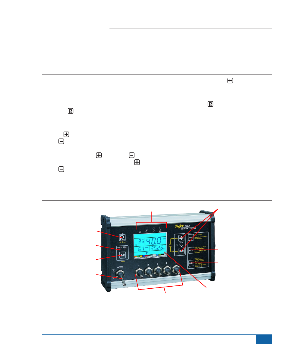
Figure 2-1: 854 Console
Sensor LED Alarms
On/Program button
Auto/Manual mode indicator
Auto/Man key
Press and hold the AUTO/MAN key to reset the
value to “0” or restore factory default settings during
some steps.
Press the PROGRAM key to advance the system
to the next program step. After the nal program step
is complete, the console will nish the programming
loop and return to the initial programming step.
System Setup mode contains the options that
customize the controller to the sprayer or sprayer
components. These include calibration steps and
parameters that seldom change once programmed.
Application Setup mode contains settings that are
frequently changed (tip spacing, number of tips per
boom section, density, nozzles used, and target
application rate).
Plus and Minus keys
Preset key
Tank key
Memory key
Master Switch
Boom Section Controls
Display
www.teejet.com
1
Page 7
854 Sprayer Control
Power On the Console
The 854 console can be powered on by pressing
the PROGRAM key one time. The console will
initially display the software version at the top of
the screen and the serial number of the console
at the bottom of the screen. After approximately
5 seconds, the console will enter into swath width
view.
Press the PROGRAM key to advance to normal
Operations mode.
Figure 2-2: Power On the Console
SFt
H28
1.20
0008
Power O the Console
To power off the 854 console, press and release the
MINUS and PROGRAM keys simultaneously.
The console will save new information (area and
volume counters) to memory before it powers down.
The console also has an automatic power down
feature. This is described in further detail in the
Features section of this User Guide.
Figure 2-3: Power Off the Console
2
www.teejet.com
Page 8
854 Sprayer Control
CHAPTER 2 - OEM PROGRAM MODE
The OEM Program Mode contains conguration steps for the console. The console is typically pre-congured
before being shipped. Changing the congurations is not recommended unless instructed to do so as it may
adversely affect the performance of the controller.
• To enter the OEM Program Mode:
• Begin with the console powered “Off”.
• Press the MINUS key and the PROGRAM
key simultaneously to turn the console “Off”
if required.
• Press and hold the PLUS and MINUS
keys. While still holding them, press the
PROGRAM key 4 times.
• Release all keys.
Figure 3-1: Entering OEM Program Mode
nr
5
• Press and hold the AUTO/MAN key for 3
seconds to set the value to “1”.
• Press the AUTO/MAN key once to reset the
value to the default value of “5”.
• Press the PROGRAM key to accept the
value and advance to the next program step.
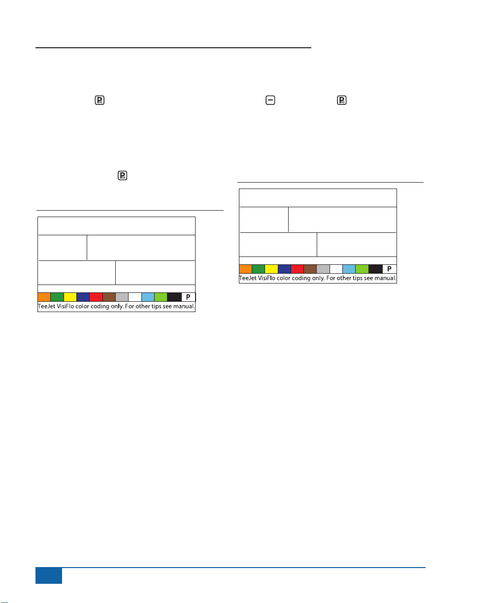
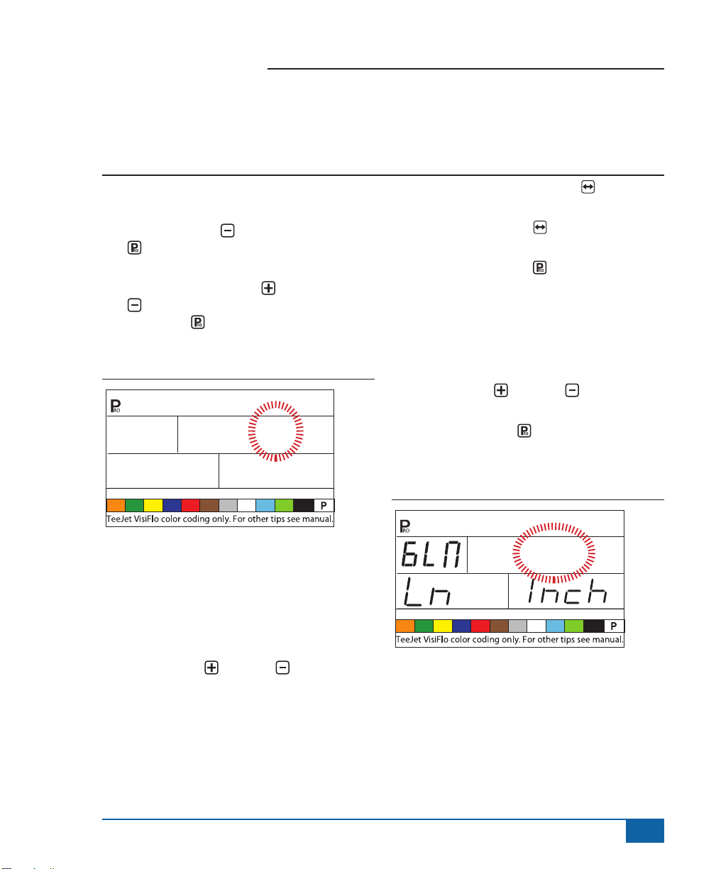
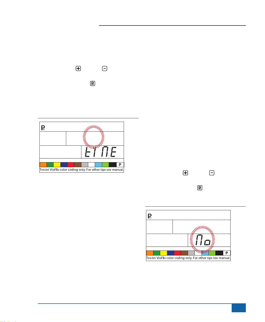
Lane Width (GLM Working Units)
When Gallons per Lane Mile “GLM” is selected as
the working units, this screen will allow the operator
to enter the lane width in inches.
• Use the PLUS or MINUS keys to modify
the value.
• Press the Program key to accept the value
and advance to the next program step.
SEC
Number of Boom Section
Switches On the Console
The number of individual boom section switches
actually present on the control console (regardless
of the number of boom sections that are on the
sprayer) can be programmed.
• Use the PLUS or MINUS keys to modify
the value.
• 1 to 11 switches can be programmed.
• This number will determine the number of spray
tips per boom section during the System Setup
Mode.
Figure 3-2:
Lane Width (GLM Working Units) Window
144
www.teejet.com
3
Page 9
854 Sprayer Control
Regulation Parameters
The regulation algorithm is congured with the next
three parameters:
1. Minimum Regulating Valve Voltage: the
minimum voltage that can drive the regulating
valve.
2. Regulation Stop Band: the maximum allowed
application error rate.
3. Rotation Time of Regulating Valve: the total
time required to close the regulating valve at
maximum speed.
These three OEM parameters depend on the
regulating valve used.
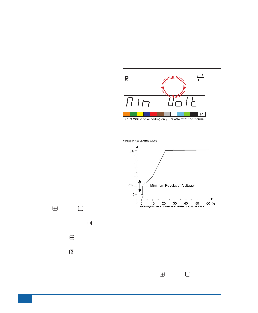
Minimum Regulating Valve Voltage
The console uses variable voltages to drive the
regulating valve. Select the minimum voltage that
the regulating valve needs to make it turn at its
slowest rotation speed (i.e., if the motor of the
regulating valve turns with a minimum of 3.5v, the
number should be used in this location).
The affect of this parameter on the regulation
behavior is illustrated in Figure 2-4. This value must
match the actual operation of the regulating valve
used. Check with the valve manufacturer for the
value.
• Use the Plus or MINUS keys to change
the voltage.
• Press and hold the AUTO/MAN key for 3
seconds to set the value to “0.0”.
• Press the AUTO/MAN key once to set to the
default value of 3.5v.
• Press the PROGRAM key to accept the
value and advance to the next program step.
NOTE: Standard TeeJet Technologies regulating
valve minimum voltage is 3.5v.
If 12v is selected as a minimum voltage, no variable
voltage regulation occurs. Instead, a pulse regulation
occurs. This is necessary when using solenoid
operated regulating valves (i.e., a Ramsay valve).
Figure 3-3: Minimum Regulating Valve Voltage
rE6
Figure 3-4: Voltage Comparison
3.5
Regulation Stop Band
The Regulation Stop Band is the maximum error
percentage allowed on the application rate before
the regulating valve reacts (i.e., if a stop band of
1.5% is selected, there is no action on the regulating
valve if the actual application rate is within 1.5% of
the target rate). This minimum percentage prevents
the regulating valve from oscillating in a narrow band
around the target point.
• Use the PLUS or MINUS keys to change
the regulation stop band (value is expressed
4
www.teejet.com
Page 10
854 Sprayer Control
0102030405060 %
V
in error percentage). The maximum value is
10.0%.
• Press and hold the AUTO/MAN key for 3
seconds to set the value to “0.0”.
• Press the AUTO/MAN key once to set the
value to the default setting of “1.5%”.
• Press the PROGRAM key to accept the
value and advance to the next program step.
Figure 3-5: Regulation Stop Band
rE6
STP
Figure 3-6: Effects of Parameters
oltage on REGULATING VALVE
14
1.5
BAnd
Rotation Time of Regulating
Valve
The Rotation Time of Regulating Valve is the number
of seconds the regulating valve needs to turn from
the complete closed position to the complete open
position at the nominal voltage (i.e., 14v).
Use the PLUS or MINUS keys to change
the rotating time of the regulating valve in seconds
(minimum “0’s”, maximum “50’s”).
Press and hold the AUTO/MAN key for 3 seconds
to set the value to “0.0”.
Press the AUTO/MAN key once to set the value
to the default setting of “6 seconds”.
Press the PROGRAM key to accept the value
and advance to the next program step.
NOTE: Standard TeeJet regulating valve rotation
time is 6 seconds.
The console uses this parameter to control the
regulation speed. The value must match the actual
operation of the regulating valve used. Check with
the valve manufacturer for this value.
Figure 3-7: Rotation Time of Regulating Valve
0
Regulation Stop Band
Percentage of DEVIATION between TARGET and DOSE RATE
rE6
SPd
6
SEC
www.teejet.com
5
Page 11
854 Sprayer Control
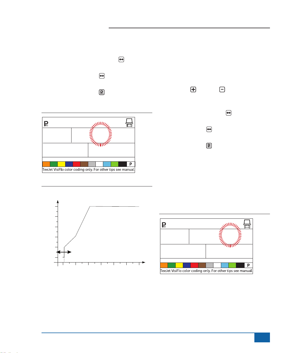
Display Stabilization
Display Stabilization establishes the stabilization
rate that steadies the Application Rate displayed
during minor adjustments of the control system.
The controller will continue to make the required
adjustments at all times. Enter the percentage of
allowable change from the target rate in this step.
For example, the system has a target rate of 20 GPA
with 5% programmed for Display Stabilization. The
display will indicate 20 GPA at any time the actual
rate is +/- 5%, or:
• Use the PLUS or MINUS keys to change
the value.
• Press and hold the AUTO/MAN key for 3
seconds to set the value to “0.0”.
• Press the AUTO/MAN key once to set the
value to the default setting of “5%”.
• Press the PROGRAM key to accept the
value and advance to the next program step.
NOTE: The Display Stabilization value is limited to
20%. A value of 0% will disable the setting.
Figure 3-8: Display Stabilization
s O
diS
5
rAtE
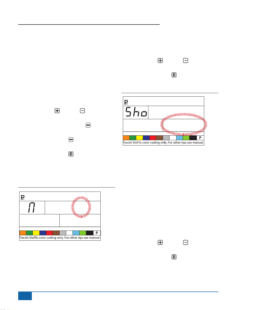
Data Display Screen Options
The lower right hand display used during normal
operations mode can be customized to display:
• volume sprayed
• area covered
• both volume sprayed and area covered
(alternating every 3 seconds)
To customize the data display options:
• Use the PLUS or MINUS keys to change
the data to be displayed.
• Press the PROGRAM key to accept the
value and advance to the next program step.
Figure 3-9: Data Display Screen
dAt bOth
Calibrate Tip Level Percent
If both a pressure sensor and a ow meter are
installed and being used, the 854 uses one sensor to
cross check the other for system errors.
Select the primary sensor (used for regulation) in
the Sensor Select step of System Setup Mode. The
opposite sensor will automatically perform the crosschecking function.
The Calibrate Tip Level % will establish the % of
allowable error between the sensors before an
alarm is activated. All sprayer systems have some
discrepancy between pressure and ow due to
pressure drops and positioning of sensors.
• Use the PLUS or MINUS keys to change
the % of allowable error.
• Press the PROGRAM key to accept the
value and advance to the next program step.
NOTE: It is recommended that this value remain at
50% unless instructed otherwise.
6
www.teejet.com
Page 12
854 Sprayer Control
Figure 3-10: Calibrate Tip Level %
CAL
50
tIP LEv
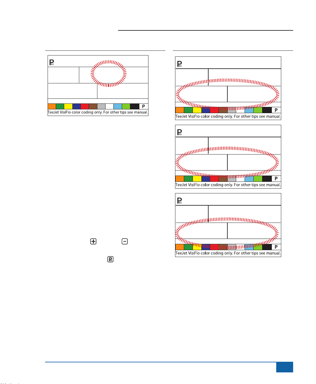
Digital Output #2
The primary output from the console computer
drives the pressure regulating valve. A second
output is available and can be congured for the
following uses:
• Not Used - the second digital output is not used
• Dual Boom - used to control a shutoff valve
on a second boom line that is automatically
activated based on speed and pressure
• Fill Valve - used to automatically shut off a
valve or switch during a tank lling operation
when used with a tank ll ow meter
To establish the Digital Output settings:
• Use the PLUS or MINUS keys to change
the value.
• Press the PROGRAM key to accept the
value and advance to the next program step.
Figure 3-11: Digital Output # 2a
Out
nOT
Out
dUA
Out
FiL
2
USEd
2
bOOn
2
vALV
www.teejet.com
7
Page 13
854 Sprayer Control
db
SPd
re6
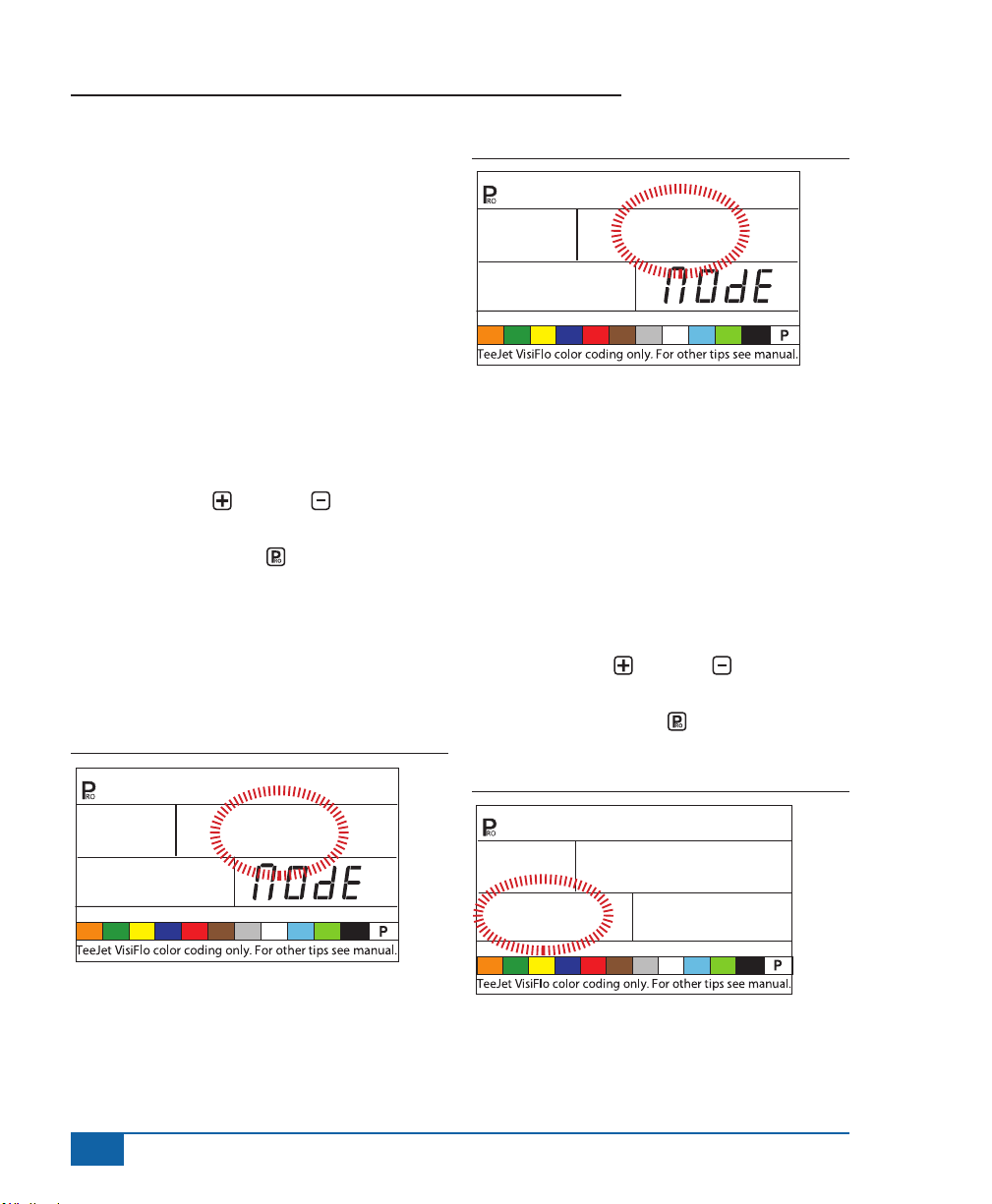
Dual Boom Regulation Mode
NOTE: This step will only be displayed if “Dual
Boom” was selected during the DIGITAL
OUTPUT #2 step.
Dual Boom Regulation Mode is used to regulate
the dual boom feature by either speed (SPD) or
pressure (PRS).
If speed is used to regulate the mode, when the
vehicle reaches the designated speed, the second
boom line will turn On/Off.
If pressure is used to regulate the mode, when
the pressure reaches the designated amount, the
second boom line will turn On/Off.
• Use the PLUS or MINUS keys to change
the value.
• Press the PROGRAM key to accept the
value and advance to the next program step.
The value selected will determine how programming
steps appear during System Setup Mode. Specic
speed or pressure values to be used during
operation are selected during the System Setup
Mode.
Figure 3-12: Dual Boom Regulation Mode - Speed
Figure 3-13: Dual Boom Regulation Mode - Pressure
db
PrS
re6
Fill Valve Default
NOTE: This step will only be displayed if “Dual
Boom” was selected during the DIGITAL
OUTPUT #2 step.
The Fill Valve Default establishes the normal
operating state of the ll valve being used. If the ll
valve requires a +12v signal during the spraying
operation, the valve default is “On”. If the ll valve
requires a +12v signal during the lling operation,
the valve default is “Off”.
• Use the PLUS or MINUS keys to change
the value.
• Press the PROGRAM key to accept the
value and advance to the next program step.
8
db
re6
www.teejet.com
SPd
Figure 3-14: Fill Valve Default
FiL
OFF
OUt
dFLt
Page 14
854 Sprayer Control
Auto Power Down
The 854 console is designed to automatically power
down after 10 minutes of inactivity from the sensor
or operator. To adjust the length of time:
• Use the PLUS or MINUS keys to change
the value of the power down time.
• Press the PROGRAM key to accept the
value and advance to the next program step.
NOTE: If the Power Down Time is set to “0”, the
Auto Power Down feature will be disabled.
Figure 3-15: Auto Power Down
Pur
10
Off
TEEJET COMMUNICATION
SYSTEM TCS CONFIGURATION
NOTE: If the TeeJet Communication System (TCS)
package was not purchased for this console,
the next 2 programming steps DO NOT
pertain to your spraying operation. IF THIS
IS THE CASE, THESE VALUES SHOULD
BE LEFT AT THE DEFAULT SETTINGS.
Job Operating System
• Job No (Default) - the console uses application
parameters entered by the operator only
• Job Only - the console uses application
parameters entered from the TeeJet
Communication System only
• Job Both - the console accepts application
parameters for both the operator and the TeeJet
Communication System
To establish the Job Operating System settings:
• Use the PLUS or MINUS keys to change
the value.
• Press the PROGRAM key to accept the
value and advance to the next program step.
Figure 3-16: Job Operating System
JOb
www.teejet.com
9
Page 15
854 Sprayer Control
Console Identication Number
The TeeJet Communications System (TCS) is
capable of monitoring and communicating with
several consoles at one time. Therefore each
console communicating with a single TCS must
be assigned a unique identication number. THE
DEFAULT NUMBER IS “1”.
• Use the PLUS or MINUS keys to change
the value.
• Press the PROGRAM key to accept the
value and advance to the next step.
Figure 3-17: Console Identification Number
1
Id
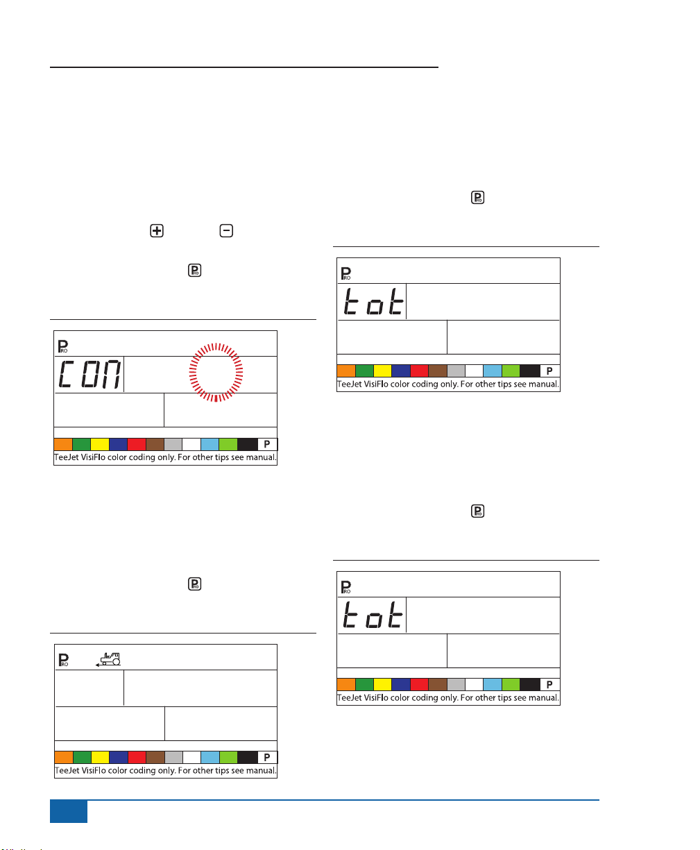
Maximum Speed Achieved
The Maximum Speed Achieved feature records the
maximum speed achieved by the sprayer. This value
can only be cleared by an authorized TeeJet Dealer,
Distributor, or Representative.
• Press the PROGRAM key to advance to the
next step.
Figure 3-18: Maximum Speed Achieved
Hidden Area Counter
The Hidden Area Counter can only be viewed and
cleared during this step. This value can only be
cleared by an authorized TeeJet Dealer, Distributor,
or Representative.
• Press the PROGRAM key to advance to the
next step.
Figure 3-19: Hidden Area Counter
Ar
1480
Hidden Volume Counter
The Hidden Volume Counter can only be viewed
and cleared during this step. This value can only be
cleared by an authorized TeeJet Dealer, Distributor,
or Representative.
• Press the PROGRAM key to advance to the
next step.
Figure 3-20: Hidden Volume Counter
Ac
uOL
Vol
4630
5.3
10
SPd
MPH
High
www.teejet.com
Page 16
854 Sprayer Control
PRESSURE TRANSDUCER
CALIBRATION P HI
NOTE: This step may not appear if the console has
not been programmed during System Setup
Mode for use with a pressure sensor.
WARNING! It is not recommended that this
calibration procedure be initially performed.
It should ONLY be performed if a known
pressure drop exists between the Pressure
Transducer and the spray tips and if a TeeJet
representative recommends performing it.
The pressure sensor can be automatically calibrated
to compensate for pressure loss between the
pressure transducer and the spray tips.
• Press and hold the PLUS and MINUS
keys to start the Auto Calibration process. The
lower left hand screen will go blank.
• Place an accurate manual pressure gauge in
the spray line, as close to the spray tips as
possible.
• Activate the pump and boom sections to be
used for calibration.
• Turn the Master Switch to the “On” position.
• Press the PLUS or MINUS keys to adjust
the pressure on the manual pressure gauge
near the tips to the desired pressure to be used
for the calibration. The higher the pressure the
better.
• Turn the Master Switch to the “Off” position.
• Use the PLUS or MINUS keys to adjust
the displayed pressure to match the actual
calibration pressure.
• Activate the pump and boom sections to be
used for calibration.
• Conrm that the actual pressure matches the
displayed pressure.
• Press the PROGRAM key to begin
calibration.
• The console will display “0-10” during the
calibration process.
• The new Pressure Transducer Maximum Rating
will be displayed. The value is automatically
carried over to the System Setup Mode.
• Press the PROGRAM key to advance to the
next step.
Figure 3-21: Pressure Transducer Calibration
145
PSI
PrS
75
PSI
PHi
SenS
16.2
206
www.teejet.com
11
Page 17

854 Sprayer Control
Figure 3-22: Memory Save Function
112
PSI
1-10
112
PSI
PrS
Memory Save Function
The Memory Save Function allows for a custom
set of programming parameters. Typically, this is
performed after all three programming sections have
been completed for the console.
Select “Yes” to save all program settings to memory.
These settings can be recalled in the System Setup
Mode during the Mem Load function.
This function is typically used to get the console
back to the starting point after unknown changes
have been made to the program modes.
• Use the PLUS or MINUS keys to select
either “Yes” or “No”.
• Press the PROGRAM key to accept the
value and advance to the next step.
PHi
SenS
PHi
SEnS
SAvE
yes
SAvE
The OEM Programming Mode of the 854 is now
complete. Press the PROGRAM key to return to
the beginning step of the process. Press and hold
the PROGRAM key to exit and save the OEM
Setup Mode. This can be performed at any time
during OEM programming. The console will exit the
OEM programming and return to normal operations.
12
www.teejet.com
Page 18

854 Sprayer Control
CHAPTER 3 - SYSTEM SETUP MODE
The System Setup Mode contains the programming steps that customize the controller to the sprayer
components. These include the calibration steps and parameters that seldom change once programmed.
To enter into System Setup Mode, power on the unit. Press and hold the PROGRAM key for 3 seconds
while in operating mode.
Selection of Working Units
The 854 is capable of working in units of:
• US (US Gallons Per Acre)
• TRF (Turf) (US Gallons/1000 ft2)
• IMP (Imperial Gallons Per Acre)
• NH3 (Pounds of N per Acre)
• GLM (US Gallons Per Lane Mile)
• SI (Metric Liters Per Hectare)
To establish the selection of working units:
• Press the PLUS or MINUS keys to select
the appropriate units.
• Press the PROGRAM key to accept the
value and advance to the next program step.
Figure 4-1: Selection of Working Units
US
vnit
Reset to Defaults
NOTE: If no changes were made to the units, this
step is skipped and setup will automatically
advance to the Speed Sensor Calibration
Step.
If changes have been made to the units during the
rst programing step, the console will inquire if all
the program parameters should be reset to the
defaults specied for the units chosen.
• Press the PLUS or MINUS keys to select
either “Yes” or “No”.
• Press the PROGRAM key to accept the
value and advance to the next program step.
Figure 4-2: Reset Defaults
res
uS
YES
dFLt
www.teejet.com
13
Page 19

854 Sprayer Control
Speed Sensor Calibration
NOTE: During Speed Sensor Calibration, the 854
automatically senses whether a Wheel
Speed or Radar Speed Sensor is being
used.
Proximity/Magnetic Pulses
The speed sensor must be calibrated to provide the
proper speed and area readings. The value for this
step is the number of pulses generated by the speed
sensor in 300 feet (100 meters).
Figure 4-3: Proximity/Magnetic Pulses
Spd
CAL
250
Automatic Calibration
NOTES: When the Automatic Calibration Mode is
activated, “CAL” is displayed on the lower
right of the display.
It is best to perform the automatic speed
calibration process at least twice and use the
average of the speed calibration numbers.
The auto speed calibration process should
take place with the sprayer tank 1/2 full.
• Mark off a distance of exactly 300 feet (100
meters).
• Press and hold the PLUS and MINUS
keys simultaneously for 3 seconds to activate
the auto calibration mode.
• Start driving toward the start point of the 300
feet (100 meter) course.
• As the starting point is crossed, press the PLUS
keys once to begin the calibration process.
• The 854 will count the pulses generated while
the course is driven.
• As the ending point is crossed, press the PLUS
key once. The number displayed on the
screen is the speed calibration number.
• If the console determines that a radar speed
sensor is connected, it will display “rAd” on the
lower left part of the display.
Figure 4-4: Automatic Calibration
CAl
Once the calibration number has been determined, it
must be entered into the console.
• Press the PROGRAM and PLUS keys
simultaneously to put the console into Radar
Mode. When the control console is in Radar
Mode, it will display “rAd” in the lower part of
the console display.
• Use the PLUS or MINUS keys to adjust
the value.
• Pressing the AUTO/MAN key will reset the
speed calibration to the default value.
• Once the correct vale has been entered, press
the PROGRAM key to validate the value and
advance to the next step.
14
www.teejet.com
Page 20

854 Sprayer Control
NOTE: When the Automatic Calibration Mode is
activated, no other functions are possible
until the console receives pulses for
calibration. To deactivate the Automatic
Calibration Mode, press the Plus key
until a number is displayed.
Figure 4-5: Radar Calibration
SPd CAL
rAd
Distance Counter
The Distance Counter feature is not a calibration
step. No specic value must be entered here for
the controller to operate correctly. This feature
measures distance in feet (meters). It can be used
to conrm Automatic Speed Calibration.
• To activate the counter, turn the Master Boom
Switch “On”.
NOTE: To avoid spraying during this process,
toggle the individual boom sections “Off”.
• To stop the counter, turn the Master Boom
Switch “Off”.
• To clear an existing distance value, press and
hold the AUTO/MAN key for 3 seconds.
1000
at the finish point. The distance measured
should be 300 feet (100 meters) (+/- 6 feet)
(+/- 1.8 meters).
Figure 4-6: Distance Counter
dst
Ctr
ft
456
Pressure Hold
NOTE: This step will appear if “GLN” was selected
for Working Units instead of Pressure
Sensor.
The Pressure Hold setting will determine whether
the sprayer will hold a constant pressure, regardless
of ground speed, or adjust to pressure according to
ground speed.
• Use the PLUS or MINUS keys to select
“Off” or “On”.
• Select “Off” to have the sprayer hold a constant
pressure.
• Select “On” to have the sprayer adjust the
pressure according to ground speed.
• Press the PROGRAM key to accept the
value and advance to the next step.
NOTE: To confirm Automatic Speed Calibration,
first complete the calibration procedure.
Advance to the Distance Counter step.
Drive the vehicle across the same 300 feet
(100 meters) course, turning the Master
Switch “On” at the starting point and “Off”
www.teejet.com
15
Page 21

854 Sprayer Control
Figure 4-7: Pressure Hold
Off
PrS
Pressure Sensor Installed
NOTE: If “No” is selected in this step, the next
two screens/steps in this User Guide will
not be displayed on the console during
programming.
The Pressure Sensor Installed step indicates to the
console whether or not a pressure sensor has been
installed on the sprayer.
• Use the PLUS or MINUS keys to select
“Yes” or “No”.
• Select “Yes” if a pressure transducer is
installed.
• Select “No” if a pressure transducer is not being
used.
• Press the PROGRAM key to accept the
value and advance to the next step.
Figure 4-8: Pressure Sensor Installed
YES
PrS
SEnS
Pressure Transducer Low
Pressure Calibration (P Ref)
This function is used to calibrate the Zero Pressure
setting of the pressure transducer installed on the
system. The pressure transducer used with the 854
is a current type transducer and uses a 4-20 mA
reading. “4.0 mA” represents “Zero” pressure.
Figure 4-9: Pressure Transducer
0
PSI
rEF
Automatic Calibration
• Make sure that the sprayer pump is turned off
and that there is absolutely no pressure in the
system (release pressure held by boom control
valves and nozzle body check valves).
• In some cases it may be best to remove the
sensor from the plumbing system to complete
the calibration.
• Press and hold the PLUS and MINUS
keys simultaneously for 3 seconds to activate
the automatic calibration feature.
• The lower left portion of the display will count
from 1 - 10 during the calibration.
• Once the display nishes counting, it should
display a number close to 4.0 (+/- 0.2).
• The low pressure value of the transducer has
been calibrated.
• Press the PROGRAM key to advance to the
next step.
4.00
nA
16
www.teejet.com
Page 22

854 Sprayer Control
Figure 4-10: Automatic Calibration
0
PSI
1-10
0
PSI
REF
Pressure Transducer Maximum
Rating (P HI)
The Pressure Transducer Maximum Rating is used
to establish the maximum rating of the pressure
transducer in the system. This number can be found
stamped on the pressure transducer itself.
• If the transducer has a maximum rating of 145
psi (10 bar) and the number is shown on the
display, advance to the next step by pressing
the PROGRAM key.
• If the maximum rating is 363 psi (25 bar), use
the PLUS or MINUS keys to change the
value.
• Press the PROGRAM key to advance to the
next step.
4.00
88
4.13
nA
The Maximum Pressure cannot be set lower
than the Minimum Pressure.
Figure 4-11: Pressure Transducer Maximum Rating
145
PSI
PHi
PrS SEnS
Flow Meter Installed
NOTE: This step may not appear if other
programming steps have indicated that a
flow sensor is present.
The Flow Meter Installed step indicates to the
console whether a ow meter has been installed on
the sprayer.
• Use the PLUS or MINUS keys to adjust
the value.
• Select “Yes” if a ow meter is installed. Select
“No” if a ow meter has not been used.
• Press the PROGRAM key to advance to the
next step.
Figure 4-12: Flow Meter Installed
YES
FLO
SEnS
NOTES: Do not change the value to “0” even if
there is no pressure sensor installed.
www.teejet.com
17
Page 23

854 Sprayer Control
Flow Meter Pulses
NOTE: This step may not appear. It only appears if
the Flow Meter Installed step is set to “Yes”.
In the Flow Meter Pulses step, the ow meter
calibration number can be manually entered from
the factory calibrated tag, or an automatic calibration
procedure can be started to determine the ow
meter pulses based on a known volume of uid.
NOTE: The automatic calibration procedure is
recommended for maximum accuracy.
Manual Entry
• Locate the factory-calibrated ow meter pulse
rate tag on the ow meter.
• If this varies from the default value of the
console (it typically does), use the PLUS or
MINUS keys to modify the value.
• Press the PROGRAM key to advance to the
next step.
Figure 4-13: Manual Entry
Automatic Calibration
To complete an automatic calibration of the ow
meter:
• Press and hold the PLUS and MINUS
keys simultaneously for 3 SECONDS. This
will clear the existing value and initiate the
calibration procedure.
• “CAL” will be displayed on the screen. This
indicates that the controller is ready to begin
the calibration process.
• Engage the sprayer pump.
• Press the PLUS key to activate the
calibration.
Figure 4-14: Automatic Calibration
CAL
FLO
PLS
18
www.teejet.com
CAL
650.0
CAL
0
• Turn the boom sections on and begin spraying
a known volume of uid (i.e., 100 gallons)
(378.5 liters).
• As the known amount is sprayed, the console
will count the pulses.
Page 24

854 Sprayer Control
• After the known volume has been sprayed, turn
the Master Switch “Off” to stop counting pulses.
Figure 4-15: Automatic Calibration (continued)
CAL
56
• Press the PROGRAM key. The console will
request what volume was sprayed.
• Use the PLUS and MINUS keys to adjust
the value to match the volume sprayed in
gallons/liters.
• Press the PROGRAM key to return to the
programming mode.
• The console will display the new ow meter
calibration number.
• To accept the value, press the PROGRAM
key to advance to the next step.
• To repeat the calibration procedure, refer to the
previous steps.
NOTE: A volume of at least 50 gallons (200 liters)
should be sprayed during the calibration.
The more volume used for calibration, the
more accurate the flow meter will be.
3856
Figure 4-16: Automatic Calibration (continued)
Vol
6AL
1000
Flow Sensor Minimum Flow
Capacity
NOTE: This step may not appear if the console was
not previously programmed for use with a
pressure sensor.
When both a pressure sensor and ow sensor are
installed, the 854 determines when the ow rate has
dropped below the capacity of the ow meter being
used and automatically switches to pressure-based
regulation. When the ow rate once again reaches
an acceptable level for the ow meter to regulate,
the 854 automatically switches back to ow-based
regulation.
• Use the PLUS or MINUS keys to enter
the minimum recommended ow mater, in
GPM or LPM, of the ow meter installed on the
sprayer.
• This information can be located in the ow
meter manufacturer’s literature.
• Minimum ow rates for TeeJet ow meters are
listed in the following table.
• Press the PROGRAM key to return to
accept the value and advance to the next step.
www.teejet.com
19
Page 25

854 Sprayer Control
Figure 4-17: Flow Sensor Minimum Flow Capacity
FLO
LO
Flow Meter Rates:
Nominal Flow Meter Size Minimum Flow Rate in GPM (l/min)
1/2” 0.79 GPM (3 l/min)
3/4” 1.9 GPM (7 l/min)
1” 2.6 GPM (10 l/min)
801-PP-RUB 2.5 GPM (9.5 l/min)
1 1/2” 9.2 GPM (35 l/min)
2” 19 GPM (72 l/min)
5.0
SEnS
Sensor Selection
NOTE: This step may not appear. It will only
appear if both sensors (pressure sensor
and flow sensor) have been installed and
programmed.
The 854 system can be used with either a ow
meter, pressure transducer, or both. The Sense
Selection step instructs the console which type(s) of
sensor is/are being used to control the regulation.
• Use the PLUS or MINUS keys to
select either “Flo” for Flow Meter or “PRS” for
Pressure Sensor.
• Press the PROGRAM key to advance to the
next step.
If both sensors are installed on the sprayer, this
process will determine which sensor is used as
the primary one for regulation. If “Flo” is selected,
the Flow Meter will be used to control ow and the
pressure transducer will be used only to display the
actual pressure. If “PRS” is selected, the pressure
transducer will be used to control the ow and
display the actual pressure.
Figure 4-18: Sensor Selection
Re6
FLO
Section Valve Type
The Section Valve Type distinguishes the type of On/
Off boom control valves installed on the machine.
There are 2 types of valves that can be used:
• 2-way valves
• 3-way valves
A 2-way control valve is simply an On/Off valve.
Flow is either directed to the boom section(s) or it is
blocked.
A 3-way control valve is known as a Bypass valve.
Flow continuously passes through this valve. When
the valve is activated (on), ow is directed to the
boom section(s). When the valve is not activated
(off), ow is directed through a bypass port back to
the supply tank.
• Change the value if required by pressing the
PLUS or MINUS keys.
• Press the PROGRAM key to accept the
value and advance to the next step.
20
www.teejet.com
Page 26

854 Sprayer Control
Figure 4-19: Section Valve Type
2
SEC
Pressure Regulating Mode
The Pressure Regulating Mode instructs the 854
where the regulating valve is plumbed into the
system. Once congured correctly, this value should
not change unless the regulating valve is physically
moved to a new point in the plumbing.
• The default value is “BYP” which indicates that
the pressure regulating valve is plumbed in a
bypass line.
• If the setting is correct, press the PROGRAM
key to accept the value and advance to the
next step.
When programmed in the Bypass Mode, with the
controller in Manual Mode “Man”, the pressure
regulating valve should:
• Close when the PLUS key is pressed.
• Open when the MINUS key is pressed.
tYPE
Figure 4-20: Pressure Regulating Mode
re6
If the pressure regulating valve is plumbed in a
supply line to the booms, it is considered in the
“throttling” position.
• Use the PLUS or MINUS keys to adjust
the value to “thr” (throttling mode). The polarity
that the console uses to control the regulating
valve will be reversed.
• Press the PROGRAM key to accept the
value and advance to the next step.
When programmed in the Throttling Mode, with
the controller in Manual Mode “Man”, the pressure
regulating valve should:
• Open when the PLUS key is pressed.
• Close when the MINUS key is pressed
Figure 4-21: Pressure Regulating Mode
bYP
re6
THr
www.teejet.com
21
Page 27

854 Sprayer Control
Regulating Valve Capacity
Enter the maximum ow capacity of the regulating
valve in Gallons Per Minute (GPM). The valve
parameters needed to drive the regulating valve
smoothly depend on the size of the valve.
• Use the PLUS or MINUS keys to adjust
the valve so that it matches the maximum ow
capacity (GPM) of the regulating valve being
used.
• Press the PROGRAM key to advance to the
next step.
Figure 4-22: Regulating Valve Capacity
re6
CAp
Common Regulating Valves:
Valve GPM
344AE-2RL 27 GPM
344AE-2RB 30 GPM
344AE-2PR 12 GPM
AA346ZR 85 GPM
AA346ZRB 85 GPM
6PM
32
Regulating Valve Speed - Coarse
Adjustment
This step allows for the adjustment of the pressure
regulating valve speed to accommodate different
application needs. Operating conditions may
necessitate a higher or lower response speed for the
regulating valve.
The coarse adjustment controls the speed of the
valve when large adjustments in ow are required by
the controller.
• Use the PLUS or MINUS keys to
increase or decrease the response time.
Any number between 0 - 19 can be selected.
0 = slow
19 = fast
If the regulating valve is plumbed in a bypass line,
the valve speed coarse adjustment number of “15”
works well in most applications.
If the regulating valve is plumed in the Throttling
position (supply line) start with a coarse adjustment
speed number of “5” and adjust the number
according to application requirements.
• Press the PROGRAM key to accept the
value and advance to the next step.
Figure 4-23: Coarse Adjustment
22
www.teejet.com
re6
spd
10
COAr
Page 28

854 Sprayer Control
Regulating Valve Speed - Fine
Adjustment
The ne adjustment controls the speed of the valve
when small adjustments in ow are required by the
controller.
• Use the PLUS or MINUS keys to
increase or decrease the response time.
Any number between 0 - 9 can be selected.
0 = slow
9 = fast
Start with a ne adjustment speed of “2”. This works
well in most situations. The number may need to be
optimized during the spraying operation.
• Press the PROGRAM key to accept the
value and advance to the next step.
Figure 4-24: Fine Adjustment
re6
spd
2
FIme
Tank Volume
In addition to accumulating the total volume applied,
the 854 tracks the volume down from the maximum
tank content to 0 gallons (liters). This allows for the
monitoring of remaining tank volume.
• Use the PLUS or MINUS keys to enter
the maximum volume of the sprayer tank in
gallons (liters).
• Press the PROGRAM key to accept the
value and advance to the next step
Figure 4-25: Tank Volume
0
NOTES: Adjusting agitation volumes can assist the
regulating valve operation.
The speed value can be adjusted to
optimize system performance. If the valve
searches for the programmed application
rate by cycling the pressure up and down
continuously, reduce the number until
the searching is minimized or eliminated.
A higher number will increase the valve
response speed and increase the rate of
adjustment.
www.teejet.com
23
Page 29

854 Sprayer Control
Low Tank Volume Alarm
The 854 console alerts the operator when nearing
the end of a tank.
• Use the PLUS or MINUS keys to enter
the volume at which the console should display
the alert. A value of “0” will disable the feature.
A visual alarm will be displayed when the low tank
level warning is reached.
Figure 4-26: Low Tank Volume Alarm
LO
25
Fill Flow Meter Calibration
NOTE: This step will not be displayed unless the
console has been programmed for use with
a fill flow meter.
The 854 console has the capability of reading
signals from a second ow meter for tank lling
purposes. This feature must be activated by the
organization selling the console kit and requires
an additional ow meter. The 854 can also be
connected to a valve or switch for automatic shutoff
of the lling operation.
Manual Entry
• Locate the factory calibrated tag on the ow
meter.
• If this varies from the default value (it usually
does) use the PLUS or MINUS keys to
modify the value.
• Press the PROGRAM key to advance to the
next step.
Figure 4-27: Manual Entry
FLO
PLS
Automatic Calibration
NOTE: To achieve an accurate flow meter
calibration, a volume of at least 50 gallons
(200 liters) should be pumped during
calibration. The more volume used for
calibration, the more accurate the flow meter
will be.
• Press and hold the PLUS and MINUS
keys simultaneously for 3 seconds. This
will clear the existing value and initiate the
calibration procedure.
• “CAL” will be displayed on the screen. This
indicates that the controller is ready to begin the
calibration procedure.
• Press the PLUS key to activate the
calibration.
• Pump a known volume of uid (i.e., 100 gallons/
liters) through the ow meter in the tank.
FLO
65.00
24
www.teejet.com
Page 30

854 Sprayer Control
Figure 4-28: Automatic Calibration
CAL
CAL
0
As the known volume is pumped, the console will
count the pulses.
• Once the volume has been pumped, turn the
pump (or ow) off to stop counting pulses.
Figure 4-29: Automatic Calibration (continued)
• Use the PLUS and MINUS keys to adjust
the value to match the volume pumped (in
gallons/liters).
Figure 4-30: Automatic Calibration (continued)
6AL
• Press the PROGRAM key to return to
programming mode.
• The new ow meter calibration will be
displayed.
• Press the PROGRAM key to accept the
value and advance to the next step.
• Follow the same procedures to repeat the
calibration process.
Figure 4-31: Automatic Calibration (continued)
1000
CAL
56
• Press the PROGRAM key. The console will
ask what volume was pumped.
3856
FIL
PLS
FLO
67.00
www.teejet.com
25
Page 31

854 Sprayer Control
Communications
The Communications step allows for the selection of
the type of communications (if any) used.
Available choices include:
• NO CON - no external communications
• PRT - memory printing
• GPS - global positioning satellite system/
variable rate communication capability
• LOG - downloading to a PC with on-the-go
capabilities
• PC - PC link
• Use the PLUS and MINUS keys select
the type of communications being used.
• Press the PROGRAM key to advance to the
next step.
Figure 4-32: Communications
prt
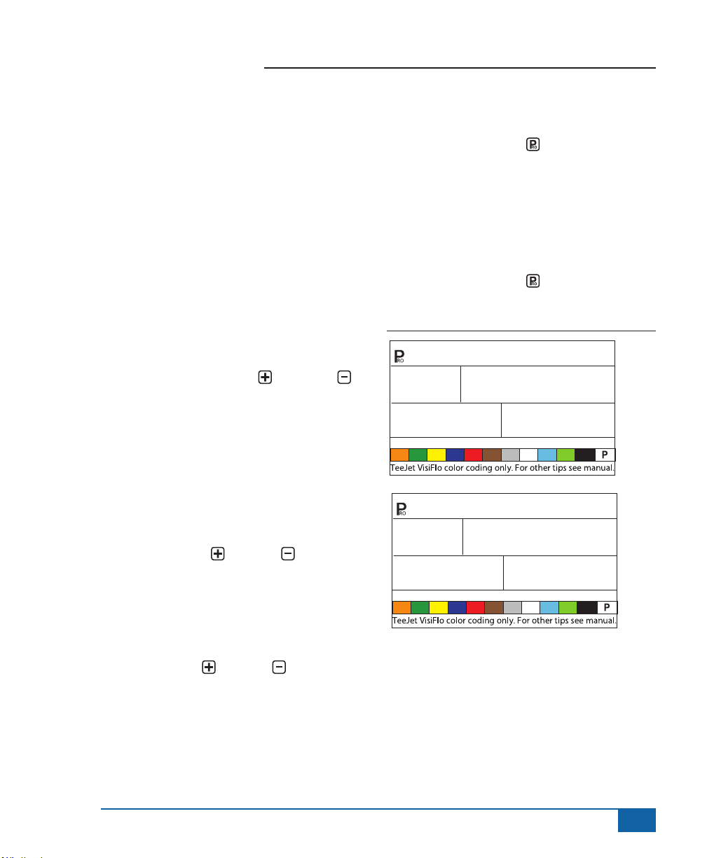
Figure 4-33: Printing Memory Contents
MeM
• Only information stored in the memory locations
can be printed.
• Press the MEMORY key to launch the PRN
TOT screen, which will allow for the printing of
contents of the Total Memory locations and any
individual memory locations (1-9) that contain
data.
Figure 4-34: Printing Memory Totals
MeM
prt
TOT
Printing Memory Contents
• Connect the 854 console to the 78-20002
printer using a 45-2004 printer cable.
• Select PRT in the Communications Setup step.
• The Boom Master Switch must be set to “Off”.
• Press the MEMORY key. The rst screen
displayed will be the MEM PRN Screen.
• Press the PROGRAM key to advance to the
next step.
26
www.teejet.com
• Continue pressing the MEMORY key to
display screens 1-9, which represent memory
locations 1-9.
• When the desired location is displayed, press
the PROGRAM key to print the report.
• To exit from the Print Menu, press and hold
either the MEMORY key or the PROGRAM
key to return to the Memory Menu.
Page 32

854 Sprayer Control
Figure 4-35: Printed Report
PRN
3
----------------------
tropeR yrammuS
----------------------
12:10 80-20-70 :etaD
----------------------
total yromeM
LAG 06.71 : emuloV
CA 01.61 : aerA
APG 00.0 :etaR naeM
-----------------------
999 tropeR gniyarpS
-----------------------
12:10 80-20-70 :etaD
________________ :dleiF
_____________ :rotarepO
-----------------------
APG 0.02 : tegraT
4 : piT
-----------------------
LAG 00.8 : emuloV
CA 06.0 : aerA
APG 03.31 :etaR naeM
HPM 04.01 :deepS .vA
-----------------------
____________ :1 mehC
___
_______________ :2 mehC
aeM
_______________ :3 mehC
_______________ :4 mehC
_______________ :5 mehC
-----------------------
________:rid/deeps dniW
________: erutarepmeT
________: ytidimuH
-----------------------
______________ :skrameR
emuloV
_______________________
aerA
_______________________
HPM 00.71 :deepS .vA
----------------------
1 yromeM
LAG 08.1 : emuloV
CA 06.0 : aerA
APG 03.3 :etaR naeM
HPM 04.7 :deepS .vA
----------------------
2 yromeM
LAG 04.3 : emuloV
CA 04.3 : aerA
APG 00.1 :etaR naeM
HPM 08.6 :deepS .vA
----------------------
3 yromeM
LAG 05.5 : emuloV
CA 06.4 : aerA
APG 02.1 :etaR n
HPM 02.6 :deepS .vA
----------------------
4 yromeM
LAG 05.2 : emuloV
CA 01.3 : aerA
APG 08.0 :etaR naeM
HPM 01.7 :deepS .vA
----------------------
5 yromeM
LAG 04.4 :
CA 94.4 :
APG 00 .1
:etaR naeM
HPM 00.7
:deepS .vA
----------------------
Using GPS
• The GPS receiver must be sending the GPVTG
string at 9600 Baud with a sampling rate of 1
Hz. Additional strings may also be sent.
• Connect the GPS receiver to the 854 console
using a 45-20063 serial cable.
• Select “GPS” in the Communications Setup
step.
• When the 854 console starts receiving speed
information from the GPS receiver, it uses that
information for determining vehicle speed. If
the 854 console loses communications with the
GPS receiver for more than 5 seconds, it will
revert back to other sources of speed input.
Figure 4-36: Using GPS Speed
6PS
Communicating With a Laptop Running
Fieldware Software
• Connect the laptop to the 854 console using a
45-20063 serial cable.
• Select “PC” in the Communications Setup step.
• Press the PROGRAM key to advance to the
next step.
• The message “GPS SPEED” will appear only
if “PC” was selected in the Communications
Setup step. Select “ON” to receiving GPS
speed through the laptop. Select “OFF” to use
the regular radar or speed sensor input.
• Follow the instructions if the Fieldware manual
to set up and run the ARM function. In System/
SystemSetup/Control, select the TeeJet854.
DRV driver.
www.teejet.com
27
Page 33

854 Sprayer Control
Figure 4-37: Communicating with Laptop/Fieldware
PC
Logging Information to a Laptop running
Logging Software
• Connect the laptop to the 854 console using a
45-20063 serial cable.
• Select “LOG” in the Communications Setup
step.
• The LOG mode is an advanced data transfer
tool used with specially congured hardware
devices only. This mode is not used during
normal applications.
Figure 4-38: Log Mode
LO6
GPS Speed
NOTE: The GPS Speed option is only available
when “PC” is selected during the
Communications Setup.
GPS Speed allows the 854 to accept speed data
from an external GPS source. Select either “On” to
use the external GPS Speed input, or “Off” to ignore
external speed input.
• Use the PLUS or MINUS keys to adjust
the value to either “On” or “Off”.
• Press the PROGRAM key to advance to the
Use External Rate step.
Figure 4-39: GPS Speed Simulation
On
6PS
Use External Rate
NOTE: The External Rate option is only
available when “PC” is selected during
the Communications Setup. This option
is typically used with an external GIS
computer, such as the Legacy 6000.
External Rate is used to indicate whether local
control rates are to be used or ignored. When set
to “Off”, the 854 console will ignore the rate coming
from the external computer and use its own preset
rate. When set to “On”, the 854 will use the rate
determined by the external computer (Legacy 6000),
usually as determined from a prescription map.
• Use the PLUS or MINUS keys to adjust
the value to either “On” or “Off”.
• Press the PROGRAM key to advance to the
Simulated Ground Speed step.
SPed
28
www.teejet.com
Page 34

854 Sprayer Control
Figure 4-40: External Rate
USe
EXT
Simulated Ground Speed
Simulated ground speed allows the verication of
console functions and the sprayer without actually
moving the sprayer. This should be tested prior to all
spraying activity.
The 854 has a low and high simulated ground speed
that allows for switching between the two to simulate
a speed change. This will ensure that the console is
regulating properly during sprayer checkout.
To activate the simulated speed, while in the normal
operating mode with the Master Switch “On”:
• Press the PROGRAM and MINUS keys
for low simulated speed.
• Press the PROGRAM and PLUS keys for
high simulated speed.
Low Speed
• Use the PLUS or MINUS keys to adjust
value.
• Press the PROGRAM key to advance to the
High Simulated Speed step.
ON
rate
Figure 4-41: Low Speed Simulation
SIM
6.0
High Speed
• Use the PLUS or MINUS keys to adjust
value.
• Press the PROGRAM key to advance to
High Simulated Speed step.
Figure 4-42: High Speed Simulation
SIM
9.0
NOTE: Once the sprayer begins moving and the
854 receives actual speed pulses, simulated
speed is deactivated. If a Radar Speed
Sensor is being used, disconnect the Radar
from the main console. Due to the sensitivity
of this speed sensor, any movement can
disable simulated speed.
SPd
MPH
LO
SPd
MPH
High
www.teejet.com
29
Page 35

854 Sprayer Control
Auto Master O - Speed
The TeeJet 854 automatically shuts the boom
sections off at the programmed speed to eliminate
an operator function when slowing to stop or turn
around.
• Use PLUS or MINUS keys to adjust
speed value.
• Press the PROGRAM key to advance to
next step.
When the sprayer speed exceeds the established
Auto Master Off Speed, the boom sections turn back
on. Set this value to “0” to disable. This feature is
disabled when operating in Manual Mode.
Figure 4-43: Auto Master Off - Speed
MIM
SPd
MPH
0.0
Minimum Pressure Setting
Set the minimum pressure to which the sprayer
is allowed to regulate. It is possible that when
the sprayer slows down, the control system will
regulate the pressure so low that it falls below the
manufacturer’s recommended pressure for the spray
tip or reduces system ow to the point where the
ow meter stalls.
Set the pressure setting to the minimum
recommended pressure range for the spray tips
being used. (For example, if this is set to 15 psi/10
bar, the console, in automatic mode, does not
regulate pressure below 15 psi/10 bar.)
• Use the PLUS or MINUS keys to adjust
the minimum pressure value.
• Press the Program key to advance to the
next step.
NOTE: An audible alarm is activated when this
feature is enabled. It will provide a steady
beep, indicating Medium Priority.
Figure 4-44: Minimum Pressure Setting
10
re6
PrS
Maximum Pressure Setting
Set the maximum pressure to which the sprayer
is allowed to regulate. This will help ensure
that the spraying pressure does not exceed the
recommended pressure range of the spray tips
being used. This step can be used to help prevent
spraying applications that contribute to drift.
• Use the PLUS or MINUS keys to adjust
the maximum pressure value.
• Press the PROGRAM key to advance to the
next step.
NOTE: An audible alarm is activated when this
feature is enabled. It will provide a steady
beep, indicating Medium Priority.
30
www.teejet.com
Page 36

854 Sprayer Control
Figure 4-45: Maximum Pressure Setting
145
Hi
Audible Alarm
The audible alarm is used to alert the operator to
problems with the sprayer control system. It is used
in addition to visual alarms on the LCD display and
LED sensor alarms above the screen.
• Use the PLUS or MINUS keys to select
“YES” to activate the audible alarm.
• Use the PLUS or MINUS keys to select
“NO” to deactivate the audible alarm.
• Press the PROGRAM key to advance to the
next step.
Audible alarms are divided into three priorities:
• Low - a long beep
• Medium - a steady beep
• High - three short beeps
Figure 4-46: Audible Alarm
re6
PrS
Dual Boom On Setting
NOTE: This step will not be displayed unless the
dual boom option was selected in the OEM
Programming Mode.
The dual boom option is the speed or pressure
at which the second boom is SHUT OFF. As the
vehicle slows, the system pressure will begin to
drop, eventually to a point where the spray tips are
no longer able to develop a pattern. The Dual Boom
On setting should be adjusted to shut off the second
boom line before this condition occurs.
• Use the PLUS or MINUS keys to adjust
the setting.
• Press the PROGRAM key to advance to the
next step
Figure 4-47: Regulating Mode - Speed
DB
Spd
OFF6.0
Figure 4-48: Regulating Mode - Pressure
Aud
YES
ALrM
15
PRs
Db
www.teejet.com
31
Page 37

854 Sprayer Control
Memory Reload Function
The memory reload function is used to restore all
programming values that were previously set. A
sprayer manufacturer can pre-program the console
for specic parameters on a sprayer and save the
values internally. This step will allow for the return to
those pre-programmed values if required.
WARNING! It is recommended that this setting be
set to “NO” unless otherwise instructed by
an authorized TeeJet representative.
Notes: For protection, the 854 console does not
automatically power down while in Program
Mode. Exit properly as described below
to enable the console’s auto power down
feature.
Cutting the power to the controller while in
Program Mode will not save any changes in
the computer’s memory.
• Use the PLUS or MINUS keys to select
either “YES” or “NO”.
• The default of “NO” indicates that programming
values are saved as entered.
• Selecting “YES” will change the program
values to those programmed and saved by the
manufacturer.
• Press the PROGRAM key to advance to
the next step. The screen should return to the
beginning of Program Mode.
• Press and hold the PROGRAM key for
three seconds to exit Program Mode and save
the programming information to the console’s
memory.
Figure 4-49: Memory Reload Function
MEM
LOADrE
32
www.teejet.com
Page 38

854 Sprayer Control
CHAPTER 4 - APPLICATION PRESET SETUP MODE
To access the Application Preset Setup Mode, the
Master Switch must be in the “Off” position.
• Press the PRESET key to display the
current presets being used.
• Press the PRESET key again within 3
seconds to advance to the next preset. This
process can be continued throughout all 5
presets.
• To program a particular preset, press the
PROGRAM key while that preset is
displayed.
Tip Spacing
Enter the spacing between the spray nozzles in
inches (cm).
• Use the PLUS or MINUS keys to adjust
the value.
• Press the PROGRAM key to advance to the
next step
Figure 5-2: Tip Spacing
Figure 5-1: Application Preset Setup
PST
15.0
-2-
EXAMPLE: To program present #2, press the
PRESET key until “PST - 2 - “ is
displayed. Press the PROGRAM key to
program the value.
20
-2-
www.teejet.com
33
Page 39

854 Sprayer Control
Number of Tips Per Boom
Section
Enter the number of tips on the boom section
corresponding to boom Section 1. The number of
tips entered here is specic to the preset being used
(in the following example, preset 2 is being used).
• Use the PLUS or MINUS keys to adjust
value.
• Press the PROGRAM key to advance to
next step
Once the PROGRAM key has been pressed,
pressing the PROGRAM key again will advance
the console to Section 2. Continue programming
the number of tips for each boom section until all 5
possible boom sections have been programmed. If
a particular boom section switch is not used, set the
value to “0”.
Figure 5-3: Number of Tips
SeC
1
6
-2-
Density
Alternate Density Used
If a product carrier other than water will be used,
change this value to “YES”. Otherwise, leave at
“NO”.
• Use the PLUS or MINUS keys to select
“YES” or “NO”.
• Press the PROGRAM key to advance to the
next step
Figure 5-4: Alternate Density
dEns
Density Value
NOTE: This screen will only be displayed if
Alternate Density Used was set to “YES”.
If a carrier other than water (i.e., liquid fertilizer) is
being used, enter the density value.
• Use the PLUS or MINUS keys to change
the value.
• Press the PROGRAM key to advance to the
next step
34
www.teejet.com
Page 40

854 Sprayer Control
Figure 5-5: Density Value
1.28
DenS
Tip Selection
Select the appropriate color of the spray tip being
used.
• Use the PLUS or MINUS keys to move
the ashing arrow to the tip’s corresponding
color tab.
The arrow should be located over the matching
color of the tips being used (tips must be ISO color
coded). The ow rate of the tip in GLM (LPM) at 40
psi/2 bar will be displayed on the lower right corner
of the screen. Press the PROGRAM key to select
the color tab and advance to the next step.
Target Application Rate
Once the tip has been selected, the Target
Application Rate display will be ashing. If the
display rate is not ashing, press the PROGRAM
key three or four times until the Target Application
display starts to ash.
• Use the PLUS or MINUS keys to adjust
the target rate.
• Press the PROGRAM key to advance to the
next step.
Figure 5-7: Target Application Rate
40
6.0
20.0
0.40
Figure 5-6: Tip Selection
40
20.0
6.0
0.40
www.teejet.com
35
Page 41

854 Sprayer Control
Calculation Steps
Known Pressure Calculation
If the approximate operating pressure is known:
• Use the PLUS or MINUS keys to adjust
the value.
The 854 will determine what the operating speed
must be to achieve the target application rate that
the entered pressure. If the indicated speed is too
high, a set of smaller nozzles is required. If the
indicated speed is too low, a set of larger nozzles is
required.
Press the PROGRAM key to advance to the next
step.
Figure 5-8: Known Pressure Calculation
40
6.0
20.0
0.40
Known Speed Calculation
• Use the PLUS or MINUS keys to adjust
the indicated speed to the intended speed.
The 854 will calculate what the pressure must be to
maintain the target application rate at the entered
speed. If the pressure is too high, a set of larger
nozzles or a slower speed is necessary. If the
pressure is too low, a set of smaller nozzles or a
faster speed is necessary.
Continue trying different speed, pressure, and tip
combinations until the desired combination is found.
NOTE: In Application Preset Mode, the tip color tab
must match the actual tips being used.
• Press the PROGRAM key to save the
changes and return to the Tip Selection Step.
• Press and hold the PROGRAM key for 2
seconds to exit Application Preset Mode.
Figure 5-9: Known Speed Calculation
40
20.0
36
www.teejet.com
6.0
0.40
Page 42

CHAPTER 5 - OPERATIONS
Sprayer Evaluation
Before spraying, check all connections related to the
Sprayer Control System. Particular attention should
be given to the sensors to ensure the console
received strong, uninterrupted signals. Make sure
connections are made and the sensors are working
properly.
IMPORTANT! When working around a sprayer or
chemicals, always wear protective clothing
and eye wear.
NOTE: It is recommended that the entire sprayer
be calibrated to prepare the machine for
operation and to diagnose spray tip wear.
Worn tips can contribute to costly chemical
waste and inaccurate spraying, regardless
of the use of a sprayer control. Calibration is
necessary to obtain the benefits associated
with a computerized sprayer control.
Partially ll the sprayer tank with water to ush the
system. Perform a visual inspection of the spray
tips to ensure all tips are delivering a good spray
pattern.
• Set the Master Boom Switch to the “Off”
position.
• Make sure the tank shutoff valve is open.
• Start the vehicle’s engine, engage the pump,
and set the RPM to that being used when
spraying.
• Turn the 854 on by pressing the
PROGRAM key.
• Ensure that the preset reference ow arrow
matches the set of tips being used.
• Verify that the 854 recognizes the simulated
speed. If the simulated speed has been
854 Sprayer Control
disabled (due to vehicle movement)
activate the simulated speed by turning the
Master Boom Switch “On” and pressing
the PROGRAM and MINUS keys
simultaneously for a Low simulated speed,
or by pressing the PROGRAM and
PLUS keys simultaneously for a High
simulated speed.
• Turn each individual spray boom section “On”.
Figure 6-1: Sprayer Evaluation
40.0
6.0
• Press the AUTO/MAN key so that the red
LED indicates “MAN” mode.
• Toggle the Master Boom Switch to the “On”
position.
• Adjust the pressure with the PLUS or
MINUS keys. The pressure should increase
when the PLUS key is pressed and
decrease when the MINUS is pressed.
Check the sprayer to ensure it is activated. Visually
ensure spray tip performance.
• Press the AUTO/MAN key so that the
red LED indicates “AUTO” mode. The
control console should regulate to the target
application rate for the simulated speed.
• While spraying, press the PROGRAM
and PLUS keys simultaneously for a High
simulated speed. The 854 should increase
20.0
MPH
76
www.teejet.com
37
Page 43

854 Sprayer Control
pressure and regulate to the target application
rate for the high simulated speed.
• While spraying, press the PROGRAM and
MINUS keys simultaneously for a Low
simulated speed. The 854 should decrease the
pressure and regulate to the target application
rate for low simulated speed.
To stop spraying, toggle the Master Boom Switch to
the “Off” position.
Spraying
Fill the sprayer tank and mix the solution thoroughly.
Determine the application rate as well as the nozzles
being used. All data is programmed into the 854
console.
• Power up the 854 by pressing the
PROGRAM key.
• Toggle the individual boom switches to the “On”
position for each of the booms on the sprayer.
• Press the AUTO/MAN key so that the red
LED indicates “AUTO” mode.
• In Auto Mode, with the Master Switch set to the
“Off” position, the console will display the target
application rate and a target symbol. When
the Master Switch is set to the “On” position,
the actual rate will be displayed and the target
symbol is no longer visible.
• During application, with the Master Switch set
to the “On” position, the display will always
indicate the actual application rate, vehicle
speed, application area covered/total volume
applied, and pressure (only if a pressure
transducer has been installed).
• When the location to begin spraying has been
reached, turn the Master Boom Switch to the
“On” position. The spraying operation is now
active. Maintain the usual vehicle speed for
spraying. Moderate changes in vehicle speed
do not affect application rate. Moderate speed
uctuations are compensated for by automatic
pressure increases or decreases by the 854.
If it is necessary to stop during application, turn the
Master Boom Switch to the “Off” position.
Alarm warnings can occur momentarily while the
pressure regulating valve is searching for a new
setting (i.e., after the close of a boom section or
other change in normal operation). However, if the
alarm stays on for a longer period, the valve may
have reached its limit and the system is unable to
regulate ow beyond the limit.
38
www.teejet.com
Page 44

CHAPTER 6 - FEATURES
Area/Volume Display
WARNING! Clearing the area/volume counter
as indicated blow does not save the
information. If the information is to be saved
for future reference, refer to the Memory
Feature of this User Guide.
With the Master Boom Switch in the “On” position,
the 854 Sprayer Control counts application area and
measures the total volume applied.
The area counter measures treated acres and
is dependent on the values programmed for the
number of tips per boom section and the tip spacing.
The volume measure is dependent on ow meter
pulses, if a ow meter is present. If not, it is calculated
based on pressure signals from the Pressure
Transducer.
Depending on console programming during OEM
Setup Mode, the lower right of the console will
display:
• volume sprayed
• area covered
• both (alternating every three seconds)
To clear the area counter/volume measure:
• Set the Master Boom Switch to the “Off”
position.
• Press and hold the AUTO/MAN key for
three seconds.
• The controller will display a message asking if
the eld counter should be cleared.
• Use the PLUS or MINUS keys to select
either “YES” or “NO”.
• Press the PROGRAM key to accept the
change and return to normal operating mode.
854 Sprayer Control
NOTE: The area/volume measure can only be
cleared from the normal operating mode
with the Master Boom Switch in the “Off”
position.
Figure 7-1: Area/Volume Display
33
0.0
CLr
FLO
20.0
52.25
YES
CNTR
GPA
Ac
www.teejet.com
39
Page 45

854 Sprayer Control
Memory Feature
WARNING! Clearing the Total Memory Location will
also clear ALL individual memory locations
as well.
The TeeJet 854 has nine individual memory locations
as well as a Total Memory location. These memory
locations store the volume and area accumulated
since the last clearing of the display, or since the last
memory save function.
Viewing Memory Information
To view information stored in memory locations:
• Press the MEMORY key.
• Continue pressing the MEMORY key to
scroll through the different memory locations.
Clearing Memory Locations
To clear and existing value from a memory location:
• Press the MEMORY key.
• Continue pressing the MEMORY key to
scroll to the desired memory location.
• Press and hold the AUTO/MAN key for three
seconds.
The area/volume and volume readings will be reset
to “0”.
To clear the Total Memory Location, follow the same
procedure.
Figure 7-2: Memory Information
MEM
1-9
Vol
1080
MEM
3
Ac
0.0
Saving Information to Memory
WARNING! Saving information to a Memory
Location that has an existing value will result
in the SUM of the existing value and the new
value being stored in the memory location.
EXAMPLE: 50 Ac (Ha) and 1000 Gal (l) are on the
console
Memory Location 1 has 100 Ac (Ha) and
2000 Gal (l) previously saved
If new information is saved to Memory
Location 1, the values will be added
50 Ac (Ha) + 100 Ac (Ha) = 150 Ac (Ha)
1000 Gal (l) + 2000 Gal (l) = 3000 Gal (l)
Memory Location 1 will = 150 Ac (Ha) and
3000 Gal (l)
To save information to the memory locations:
• Press the MEMORY key.
• Continue pressing the MEMORY key to
scroll to the desired memory location.
• Press the PLUS key to save the information
The 854 will automatically exit the Memory Feature
and return to normal operating mode. Any information
saved to the individual memory locations are added
to the Total Memory as well.
40
www.teejet.com
Page 46

854 Sprayer Control
To exit the Memory Feature if no changes were made
or after clearing a value:
• Press and hold the MEMORY key for three
seconds.
Figure 7-3: Saving Information to Memory
MEM
TOT
Vol
2645
Tank Feature
Auto Tank Filling
NOTE: The Auto Tank Fill Feature can only be used
if “FILL VALVE” was selected in the Digital
Out #2 step of OEM Programming.
• Turn the Master Boom Switch to the “Off”
position.
• Press the TANK key.
• Use the PLUS or MINUS keys to enter
the volume to be added to the tank, OR
• Press the AUTO/MAN key to set the volume
to the maximum tank content.
• Press the PROGRAM key to activate the
procedure.
• Turn the Master Boom Switch to the “On”
position to activate the Fill Valve (switch).
The tank will begin lling and the console will measure
the volume. If it is necessary to stop the lling process
for any reason, turn off the Master Boom Switch.
Once the console has reached the volume to be lled,
it will automatically turn the valve off.
• Once the process is complete, turn the Master
Boom Switch “Off”.
• Press and hold the TANK key for three
seconds to return to normal operating mode.
Figure 7-4: Auto Tank Filling
FiL
1000
FiL
Off
1000
FiL
On
1000
www.teejet.com
41
Page 47

854 Sprayer Control
Tank Volume Feature
The console will count down the volume remaining
in the tank and alert the operator when the Lo Tank
Level has been reached. The Lo Tank Level can be
programmed by the operator during System Setup
Mode.
Viewing Remaining Tank Volume
• While spraying in normal operating mode, with
the Master Boom Switch in the “On” position,
press and hold the TANK key.
• The lower right display of the console will show
the volume remaining in the tank.
• When the volume reaches the pre-programmed
level, the audible alarm will activate. The display
will switch to the Tank Volume Display.
• To acknowledge the alarm, press the TANK
key or the PROGRAM key. This will return the
console to normal operating view.
NOTE: An audible alarm is activated when this
feature is enabled. It will provide a long
beep, indicating Low Priority.
Figure 7-5: Tank Volume
32
• Press the AUTO/MAN key to reset the tank
volume counter to the maximum value of the
tank volume.
• Press the TANK key or PROGRAM key
to return to normal operating view.
Figure 7-6: Resetting Tank Volume
1000
Application Alarm
If the 854 senses a continuous discrepancy of 10%
or more between the Target Application Rate and the
Actual Application Rate, the application rate window
will ash.
This will alert the operator to a problem with the
sprayer plumbing, operation, or programming.
NOTE: An audible alarm is activated when this
feature is enabled. It will provide three short
beeps, indicating High Priority.
Figure 7-7: Application Alarm
6.4
Resetting Tank Volume
To reset the tank volume:
• Press the TANK key.
• Use the PLUS or MINUS keys to enter a
partial tank volume
42
www.teejet.com
348
49
7.0
17.4
MPH
530
Page 48

854 Sprayer Control
!
Sensor LED Alarms
The 854 has sensor LED’s across the top of the
display. These LED’s help alert the operator to
problems with the sprayer, sprayer control system, or
application.
Speed Sensor LED Alarm - LED displays a
red light if the console loses speed signals.
Flow Sensor LED Alarm - LED displays a
red light if the console loses ow signals.
Pressure Sensor LED Alarm - LED displays
a red light if the console loses pressure
signals.
General LED Alarm - This LED alarm is
used for discrepancies between the ow
meter and pressure transducer if both are
installed and programmed.
No Speed Alarm
NOTE: This alarm only occurs when the Master
Boom Switch is in the “On” position.
If the 854 stops receiving pulses from the speed
sensor, the speed display window will ash. The
Speed Sensor LED Alarm will be displayed. A tractor
symbol will ash at the top of the display.
The Red LED will illuminate over the Speed Sensor
Alarm.
Figure 7-8: No Speed Alarm
45
0.0
No Flow Alarm
NOTE: This alarm only occurs when the Master
Boom Switch is in the “On” position.
This alarm indicates that the ow meter has stalled
or there is a problem elsewhere in the system. If the
854 stops receiving pulses from the ow meter, the
turbine symbol will ash at the top of the console.
The red LED will illuminate over the Flow Sensor
Alarm.
NOTE: An audible alarm is activated when this
feature is enabled. It will provide a steady
beep, indicating Medium Priority.
Figure 7-9: No Flow Alarm
0
PSI
4.8
0.0
MPH
0.0
MPH
32.50
642
GPA
Ac
NOTE: An audible alarm is activated when this
feature is enabled. It will provide a steady
beep, indicating Medium Priority.
www.teejet.com
43
Page 49

854 Sprayer Control
No Pressure Alarm
NOTES: This alarm is only active if a Pressure
Transducer was installed during System
Setup.
This alarm only occurs when the Master
Boom Switch is in the “On” position.
This alarm indicates that the pressure transducer
has failed or lost its connection. If the 854 stops
receiving a pressure signal, the pressure display
window will ash.
The Red LED will illuminate over the Pressure
Sensor Alarm.
NOTE: An audible alarm is activated when this
feature is enabled. It will provide a steady
beep, indicating Medium Priority.
Figure 7-10: No Pressure Alarm
PSI
9.0
0
20.0
MPH
740
GPA
Vol
Flow/Pressure Discrepancy Alarm
This alarm activates if there is a discrepancy
between the ow meter and the pressure transducer.
The amount of discrepancy allowed is dened by the
Calibrate Tip Level % step in the OEM Setup Mode.
If the 854 nds a discrepancy, the pressure display
window will ash. The application rate window will
also ash.
The Red LED will illuminate over the General Alarm.
NOTE: An audible alarm is activated when this
feature is enabled. It will provide a steady
beep, indicating Medium Priority.
Figure 7-11: Flow/Pressure Discrepancy Alarm
30
PSI
12.5
20.0
MPH
7.35
GPA
Ac
Boost Mode
The 854 is capable of boosting the target application
rate either up or down in 10% increments.
Boost Up
To activate boost up mode:
• Press the PLUS key.
• Each subsequent pressing of the Plus key
will increase the target rate 10%.
The amount the rate is “boosted” will be displayed for
two seconds. The target symbol will ash any time
the system is in Boost Mode.
To return to the target application rate:
• Press the MINUS key to return in 10%
increments.
• Push the PLUS and MINUS keys
simultaneously to return to the target rate
immediately.
44
www.teejet.com
Page 50

854 Sprayer Control
SMART SENSING
Figure 7-12: Boost Up
UP
20
Boost Down
To activate boost up mode:
• Press the MINUS key.
• Each subsequent pressing of the MINUS
key will decrease the target rate by 10%.
The amount the rate is “boosted” will be displayed for
two seconds. The target symbol will ash any time the
system is in Boost Mode.
To return to the target application rate:
• Press the PLUS key to return in 10%
increments.
• Push the PLUS and MINUS keys
simultaneously to return to the target rate
immediately.
Figure 7-13: Boost Down
24.0
39.50
Ac
Auto Power Down
The 854 console is designed to power itself off after
10 minutes of inactivity (or at the time specied in the
Auto Power Down setting in the OEM Setup Mode).
This feature keeps the console from draining the
battery on the sprayer, if the operator inadvertently
leaves the console powered on for an extended
period.
Auto Power Down only occurs when the Master Boom
Switch is in the “Off” position.
To manually power down the console, refer to
Powering Console On/Off.
NOTE: The Auto Power Down feature disables any
time the console is in any program mode.
Smart Sensing
With both a pressure and ow sensor installed, the
854 determines when the ow rate has dropped
below the capacity of the ow meter being used, and
will automatically switch to pressure based regulation.
When the ow rate reaches an acceptable level for
the ow meter to regulate, the 854 will switch back to
ow based regulation.
Figure 7-14: Smart Sensing
Dm
30
14.0
877
Vol
www.teejet.com
45
Page 51

854 Sprayer Control
46
www.teejet.com
Page 52

854 Sprayer Control
USER MANUAL
This User Guide provides information for software version 1.20.
T eeJet Technologies
Mølhavevej 2
9440 Aabybro
Denmark
www.teejet.com
98-05051 R3
© TeeJet Technologies 2010
 Loading...