

Page 1
844-R
Speed Compensated
Application Control
User Guide
98-05047
R0
Page 2

Table Of Contents
TABLE OF CONTENTS ............................................................................................................................. 2
INSTALLING THE SPEED SENSOR ASSEMBLY ................................................................................ 4
TEP
S
TEP
S
TEP
S
TEP
S
POWERING CONSOLE ON/OFF............................................................................................................. 7
OWER ON
P
OWER OFF
P
OPERATING INSTRUCTIONS................................................................................................................. 8
PPLICATOR CHECKOUT
A
HE SPRAYING OPERATION
T
FEATURES................................................................................................................................................. 10
REA/VOLUME DISPLAY
A
PPLICATION ALARM
A
NO F
LOW RATE FEATURE
F
OOST MODE
B
UTO POWER DOWN
A
OCATION
1 - L
Proximity Sensor (optional).................................................................................................................. 4
NSTALLING THE WHEEL MAGNETS
2 - I
NSTALLING THE MAGNETIC SENSOR
3 - I
ONFIRMING SPEED SENSOR INSTALLATION
4 - C
Magnetic Wheel Sensor......................................................................................................................... 6
Radar .................................................................................................................................................... 6
.................................................................................................................................................. 7
................................................................................................................................................ 7
LOW ALARM
Boost Up ............................................................................................................................................. 12
Boost Down......................................................................................................................................... 12
.................................................................................................................................... 4
.............................................................................................. 5
........................................................................................... 5
................................................................................ 6
............................................................................................................................ 8
........................................................................................................................ 9
.......................................................................................................................... 10
............................................................................................................................... 10
..................................................................................................................................... 11
............................................................................................................................... 11
........................................................................................................................................... 12
................................................................................................................................13
PROGRAMMING GUIDELINES............................................................................................................ 14
MPORTANT PRELIMINARY INFORMATION
I
SYSTEM SETUP MODE – TEEJET 844-R CONTROLLER............................................................... 14
ELECTION OF WORKING UNITS
S
ESET TO DEFAULTS
R
LOW METER PULSES
F
IP SPACING
T
# OF T
PEED SENSOR CALIBRATION
S
Proximity/Magnetic Pulses ................................................................................................................. 17
FLOW METER CALIBRATION............................................................................................................. 19
ETHOD
M
Step 1 – Known Value......................................................................................................................... 19
Step 2 – Programming Calibration Number....................................................................................... 19
Step 3 – Resetting Volume Counter..................................................................................................... 19
Step 4 – Spraying Known Volume....................................................................................................... 19
Step 5 – Entering a New Flow Meter Calibration Number................................................................. 20
Step 6 – Double-checking the New Value ........................................................................................... 20
ETHOD
M
Step 1 – Check Tip Size....................................................................................................................... 20
Step 2 – Count Tips............................................................................................................................. 20
Step 3 – Calculated Flow.................................................................................................................... 21
............................................................................................................................................. 16
IPS
.................................................................................................................................................. 16
1 – K
2 – K
................................................................................................................................15
............................................................................................................................... 16
NOWN VOLUME
NOWN TIP SIZE METHOD
.............................................................................................................. 15
................................................................................................................... 17
................................................................................................................ 19
................................................................................................ 14
.................................................................................................. 20
2 98-05047
R0
Page 3

Step 4 – Measure................................................................................................................................. 21
Step 5 – Adjustments ........................................................................................................................... 21
ISTANCE COUNTER
D
IMULATED GROUND SPEED
S
How To Use ........................................................................................................................................ 23
OMMUNICATIONS
C
INIMUM PRESSURE SETTING
M
................................................................................................................................22
.................................................................................................................... 22
................................................................................................................................... 23
.................................................................................................................. 24
APPLICATION SETUP MODE............................................................................................................... 24
ARGET APPLICATION RATE
T
LOW RATE SELECTION
F
ALCULATION STEPS
C
Known Speed Calculation................................................................................................................... 25
Known Pressure Calculation .............................................................................................................. 26
DAILY FLOW METER MAINTENANCE............................................................................................. 26
TROUBLESHOOTING GUIDE............................................................................................................... 27
QUICK REFERENCE GUIDE................................................................................................................. 29
YSTEM SETUP MODE
S
PPLICATION SETUP MODE
A
EATURES
F
................................................................................................................................................. 30
................................................................................................................................25
.................................................................................................................... 24
........................................................................................................................... 25
.............................................................................................................................. 29
...................................................................................................................... 30
98-05047 3
R0
Page 4
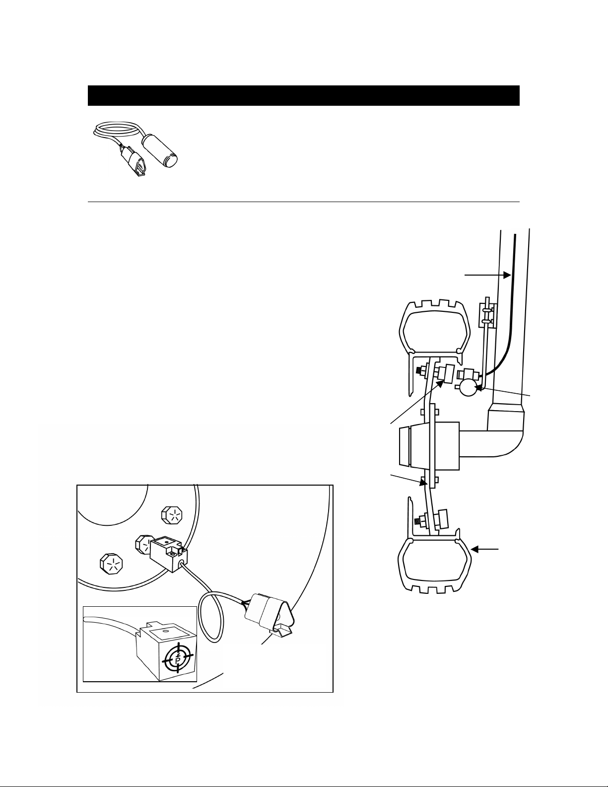
Installing the Speed Sensor Assembly
Components: Two magnets, Sensor with attached connector
cable, and mounting hardware.
If you are installing a radar ground speed sensor, follow the
instructions supplied with that unit.
S
TEP
1 - L
OCATION
The speed sensor assembly should be installed on a
non-driven wheel to avoid potential errors that are likely
to occur from a slipping drive wheel.
(Refer to Figure 1)
Proximity Sensor (optional)
An optional proximity sensor is available to use in cases
where space is limited or for drive shaft mounting. The
proximity sensor works by sensing any metal object.
Mount the proximity sensor so that the sensor face is
within 1/8 to 3/8 inch of the metal object being read.
(Refer to Figure 2)
MAGNET
RIM
CABLE
SENSOR
Figure 1
Wheel Mounting
of Magnetic
Speed sensor
TIRE
NOTE:
TARGET FACES TIRE
LUGS
4 98-05047
Figure 2
R0
Page 5
S
TEP
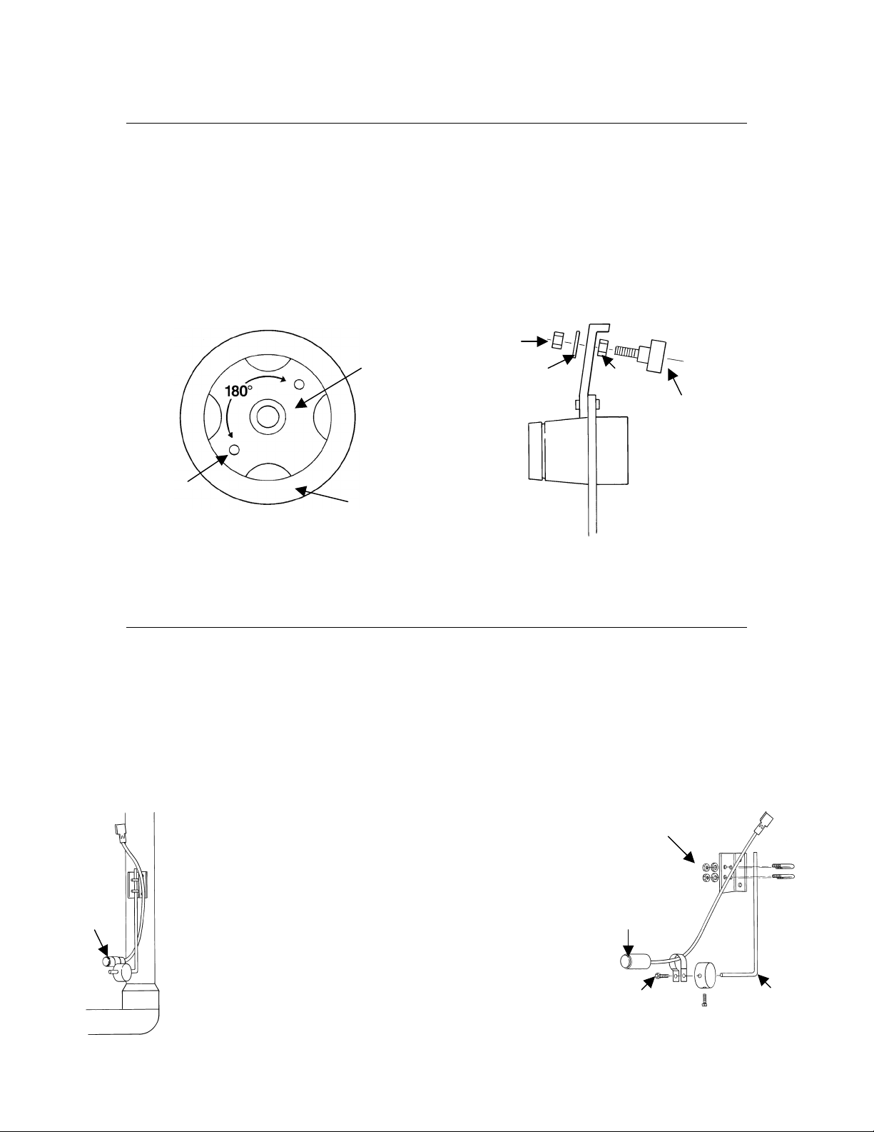
NSTALLING THE WHEEL MAGNETS
2 - I
Check for pre-drilled holes in the wheel rim. If pre-drilled holes are not available,
layout a pattern as shown in figure 3 and drill two 3/8 inch holes, locating them
near the outer rim, if possible, and 180° from each other.
Place the magnets into each of the two holes on the inside rim and securely
fasten using the nuts and washers provided. (See Figure 4)
3/8” (10 mm)
HOLE FOR
MAGNET
WHEEL
TIRE
Figure 3
Magnet Locations
NUT
WASHER
NUT
MAGNET
Figure 4
Magnet Assembly
Sensor
S
TEP
NSTALLING THE MAGNETIC SENSOR
3 - I
Secure the flat, pressed L bracket of the wheel speed sensor kit to a vertical
member near the non-driven wheel. Then secure the round, right angle steel
bracket to the flat bracket with the two U-bolts and necessary hardware provided.
Use the round, right angle bracket to secure the magnetic sensor mounting
clamp. (See Figure 5)
Insert the magnetic sensor into the mounting clamp and
position it to within 1/8 to 3/8 inch of the wheel magnet.
Tighten the sensor clamp using the clamp screw per
Figure 5A.
Figure 5
Sensor Mounting
98-05047 5
R0
Figure 5A
Sensor Assembly
Sensor
Clamp
Screw
Flat
L Bracket
Bracket
Page 6

Your installation will likely vary from the example. It may be necessary to
customize the installation to accommodate your specific machine. Keep in
mind that the two magnets must be spaced an equal distance around the
wheel. The magnetic sensor must be mounted in-line with the magnets and
positioned within 1/8 inch to 3/8 inch from each magnet as they pass the
sensor assembly.
S
TEP
4 - C
ONFIRMING SPEED SENSOR INSTALLATION
Magnetic Wheel Sensor
After the wheel or proximity sensor is installed and the 844-R console is mounted
and powered up test the speed sensor installation. Connect the wheel speed or
proximity sensor to the sensor cable and in turn connect the sensor cable to the
844-R console. When the connections are made, rotate the wheel on which the
magnets are installed. If using a proximity sensor, you will be sensing metal
objects and not magnets. Each time a magnet (metal object for proximity sensor)
passes the sensor a red LED (orange LED for proximity sensor) on the back of
the sensor will light. The LCD display on the console will also indicate a speed as
the sensor receives and sends electronic pulses.
Radar
If a radar speed sensor is used, connect it to the speed sensor connector on the
sensor end cable. An adapter cable will be necessary when using most radars
and are available through your TeeJet 844-R dealer. The 844-R will automatically
sense if the speed sensor is a wheel speed, proximity type, or radar type sensor
during calibration. The 844-R is automatically adapted to most brands of radar
speed sensors, provided that the appropriate adapter cable is used. If using a
radar sensor, the 844-R will display rAd during the calibration procedure.
6 98-05047
R0
Page 7
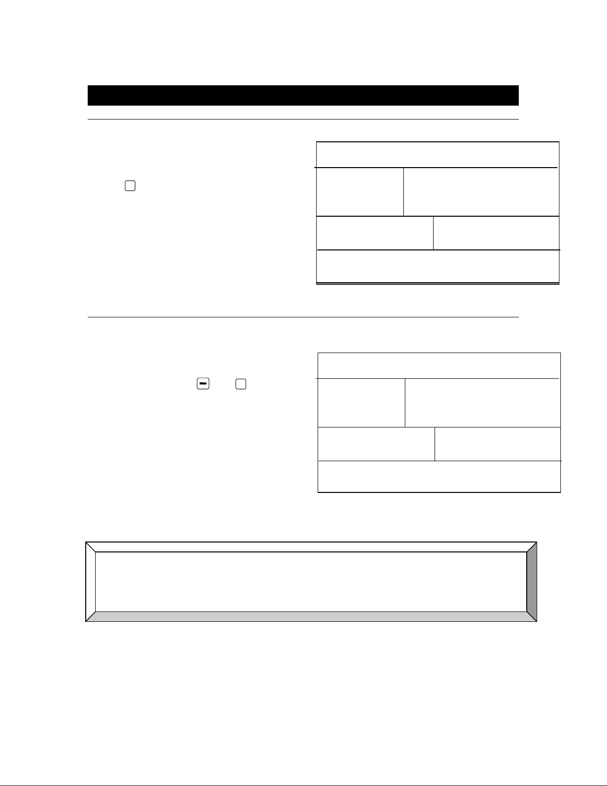
Powering Console On/Off
OWER ON
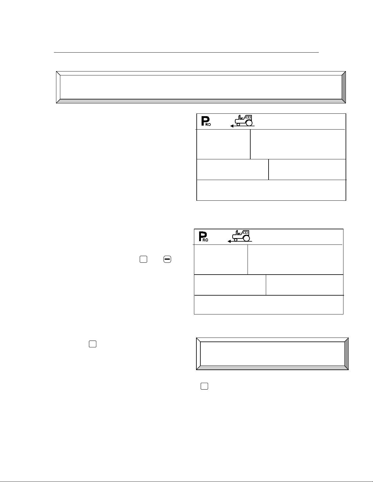
P
To power the 844-R on press the
P
RO
Initially the console displays the
software version in the top
display.
After 5 seconds the display shows
the normal operating view.
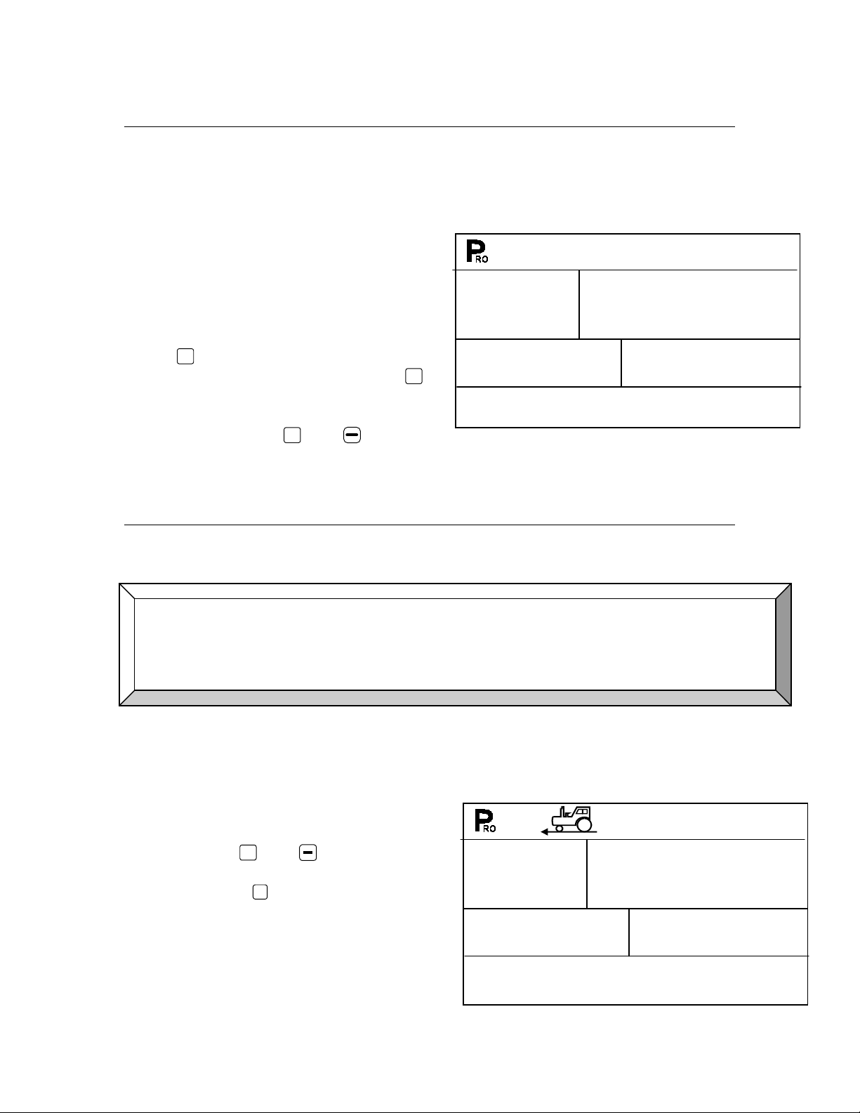
OWER OFF
P
To manually power the console
off, press the and
simultaneously.
The console saves any new
information (area and volume
counters) to memory and powers
off.
key once.
P
RO
keys
SFt
1.04
OFF
Ha
The console also has an Auto Power Down feature. When the master
switch is “off”, and no buttons are pressed for approximately
10 minutes, the 844-R will automatically power down.
Note: Both “Delivery” and “Agitation” switches still power either pump
even if console is “off”.
98-05047 7
R0
Page 8
Operating Instructions
PPLICATOR CHECKOUT
A
Before spraying, check all connections related to the Control System. Be sure
connections are made and the sensors and cabling are properly secured.
Very Important: Whenever working around chemicals, be sure to wear
protective clothing and eyewear.
Partially fill the applicator tank with water to purge the system of air and to make
a visual check of the liquid outlets to be sure liquid is exiting each outlet as
intended.
Follow these steps, in sequence, being sure the Delivery Switch is in the “OFF”
position:
Be sure the tank shut-off valve is open.
Switch the computer on by pressing the
Press the Auto/Man key so that the red LED light indicates “MAN”
mode.
Now, toggle the Delivery switch to “ON”.
Adjust the pressure with the + and keys. The pressure should
increase when you press the + key and decrease when you press the
key.
At this point, the applicator is activated and each micro-tube or orifice can be
checked.
Now press the Auto/Man key so that the red LED light indicates “Auto”
mode. The control console should regulate to the target application rate
for the simulated speed indicated. See “Simulated Ground Speed” in the
System Setup section of this manual for instructions on using simulated
speed.
To stop applying, toggle the Delivery switch to “OFF”.
The above steps provide a quick way to check out your applicator and control
system.
P
RO
key.
8 98-05047
R0
Page 9

HE SPRAYING OPERATION
T
The sprayer tank is filled and the solution thoroughly mixed. The application rate
and proper nozzles have been determined. The controller has been
programmed with the sprayer and application information.
P
Turn the control console on by pressing the
RO
key.
The Auto/Man key should be switched to “AUTO”.
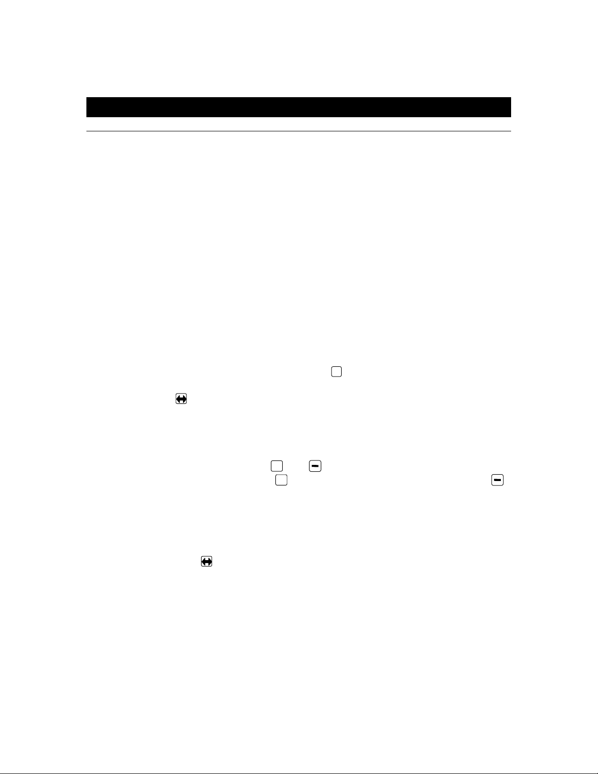
In the Auto mode, when the Delivery switch is “OFF”, the target application
rate as well as the target symbol is displayed on the console display.
When the Master boom switch is “ON”, the actual rate is displayed and the
target symbol no longer appears.
While spraying with the Delivery switch “ON”, the display always displays
the actual application rate, vehicle speed, application area covered/total
volume applied and calculated pressure. Note: If the application system is
equipped with pressure gauge, the pressure gauge may read differently
than the calculated pressure shown on the console. This does not
necessarily indicate a problem.
As you get to the point where application will begin, turn the Delivery
switch to the “ON” position. This activates the delivery pump. Moderate
changes in vehicle speed don’t affect your application rate, because such
changes are compensated for with automatic pressure adjustments by the
controller.
If it is necessary to stop, turn the Delivery switch to “OFF”.
Alarm warnings may occur momentarily while the pressure regulating valve is
searching for a new setting after a significant speed or rate change. However, if
the alarm stays on for a longer time, the valve may have reached its limit and
your system is unable to regulate flow beyond the limit.
98-05047 9
R0
Page 10
Features
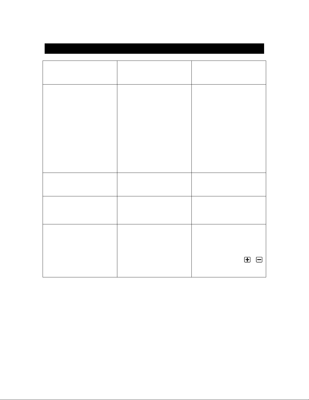
REA/VOLUME DISPLAY
A
The 844-R Sprayer Control counts application area and measures the total
volume applied while the master boom switch is in the “ON” position.
The area counter measures treated acres and is dependent on the values
programmed for the # of outlets and the tip spacing.
The volume measure is dependent on the signal from the flow meter.
The lower right of the display window shows:
Volume Sprayed and Area
Covered (alternating every 3
seconds).
To clear the area counter/volume
measure:
Be sure the Delivery switch is in
the “OFF” position
Press and hold the + or
keys for 3 seconds.
Note: The area/volume measure can only be cleared with Delivery switch
turned “OFF”.
15
PSI
0.0
MPH
2.0
56.25
GPA
Ac
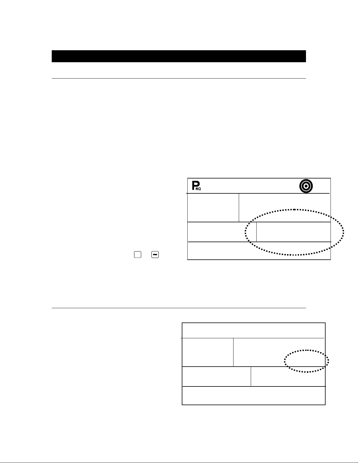
PPLICATION ALARM
A
If the 844-R senses a continuous
discrepancy of 10% or more between
the Target Application Rate and the
Actual Application Rate:
The application rate units flash.
This alerts the operator to a
problem with the applicator,
plumbing, operation or
programming.
10 98-05047
30
PSI
7.0
MPH
2.5
530
GPA
R0
Vol
Page 11

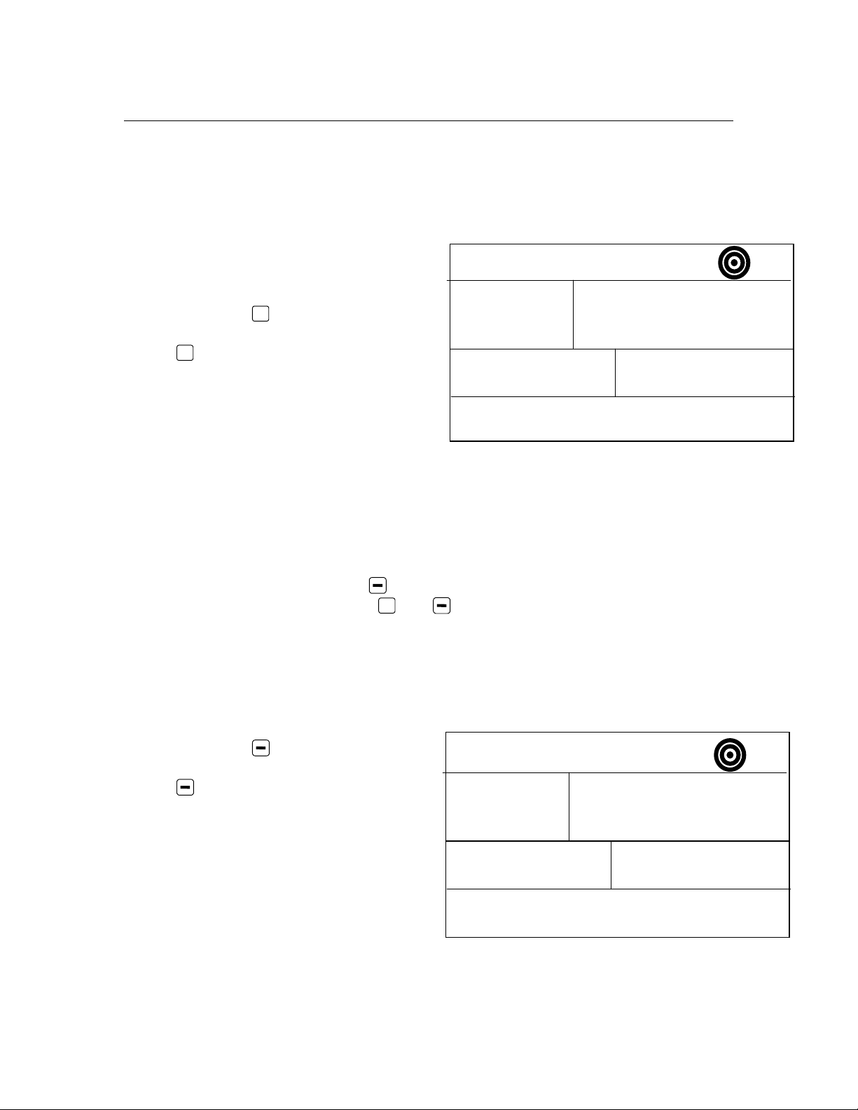
NO F
If the 844-R stops receiving pulses from the flow meter
This alarm indicates that there is a
problem with the flow meter or cabling.
F
The 844-R Sprayer Control measures a flow rate moving through the flow meter
in GPM {Imp GPM}. This feature is activated by pressing and holding the key
while spraying in the normal operating mode. The flow rate display replaces the
area/volume display in the lower right portion of the display.
LOW ALARM
The turbine symbol flashes at the
top of the display.
This alarm occurs only when the
Master boom switch is “ON”.
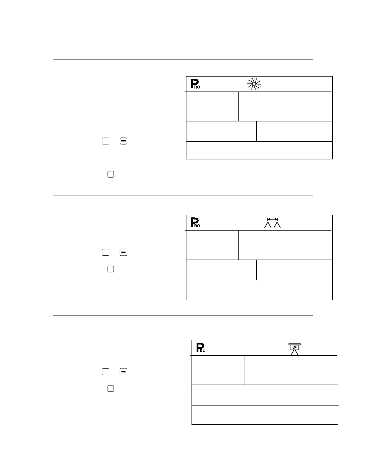
LOW RATE FEATURE
0
PSI
4.8
0.0
MPH
32.50
GPA
Ac
Any time the key is pressed while
spraying in the normal mode the flow
rate is displayed. Releasing the key
causes the display to return to
area/volume.
This feature can be used for tip
calibration or for calibrating the flow
meter. Refer to page 19 of this manual
for the flow meter calibration
procedures.
15
PSI
0.0
2.0
MPH
8.7
GPA
98-05047 11
R0
Page 12
OOST MODE
B
The 844-R is capable of boosting the target application rate either up or down in
10% increments.
Boost Up
To activate the boost up mode:
Press the + key.
Each subsequent pressing of the
+
key boosts the target rate up
10%.
The amount boosted up is shown
on the display temporarily (approx.
2 seconds).
The target symbol flashes anytime that you are in the boost mode to alert
the operator of the “off target” condition.
To return to the target application rate:
The operator can use the key to get back in 10% increments
The operator can push the + and keys simultaneously to get back to
the target in one step.
Boost Down
To activate the boost down mode:
Press the key.
Each subsequent pressing of the
key boosts the target rate
down 10%.
The amount boosted down is
recorded on the display.
The target symbol flashes
anytime that you are in the boost
mode to alert the operator of the
“off target” condition
To return to the target application rate:
Up
20
D n
30
2.4
1.4
39.50
877
GPA
GPA
Vol
Ac
12 98-05047
R0
Page 13

The operator can either use the + key to get back in 10% increments
The operator can push the + and keys simultaneously to get back to
the target in one step.
UTO POWER DOWN
A
The 844-R console is designed to power
itself off after 10 minutes of no inputs.
This feature keeps the console from
draining the battery on the sprayer if the
operator inadvertently leaves the
console powered on for an extended
period. This only occurs when the
Master boom switch is turned OFF and
the console is not receiving inputs from
any of the sensors (the sprayer is
inactive).
To manually power the console off, refer to the Powering Console On/Off section
of this manual.
Note: When the console display power is “off”, the “Delivery” and
“Agitation” switches can still be operated.
Note: When in the user setup mode, the automatic power down feature is
disabled. However, after 10 minutes without keyboard activity, the console
automatically saves all program changes and exits the program mode. At
this time, the automatic power down feature begins counting and will shut
the console off after 10 minutes.
The programming of the 844-R is divided into two programming categories;
System Setup Mode and User Setup Mode.
The System Setup Mode contains the programming steps that customize
the controller to the applicator or it’s components. These include
calibration steps and parameters that, once programmed, rarely change.
The Application Preset Setup Mode contains target application rate and
orifice or micro tube capacity settings, which are more frequently changed.
OFF
98-05047 13
R0
Page 14

Programming Guidelines
Make sure that all hardware components are properly installed and tested.
Before the programming process starts, confirm that the console and all sensors
are working properly.
MPORTANT PRELIMINARY INFORMATION
I
Before starting, we recommend that you review the following Programming
Guidelines that control the programming process:
To enter the program mode, see the appropriate program section you wish
to enter in this manual. The delivery switch must be in the “off” position to
enter any program mode.
To exit any program mode press and hold the
changes are stored and the computer exits the program mode. This action
can be done at any time during the program process.
To increase the value of a programmable digit, press the + key. To
decrease the value, press the key. These keys are located directly to
the right of the display. For some programming steps, pressing and
holding the + or key changes the programmable value rapidly.
Pressing the + or key once changes the value by one increment.
P
Pressing the
last programming step, the console completes the program loop and
returns to the first programming step.
RO
key advances you to the next programming step. After the
P
RO
key for 3 seconds, your
Due to differences in fonts, some letters on the displays shown in
this manual are not identical with the corresponding letters on the
display of the controller.
System Setup Mode – TeeJet 844-R Controller
The System Setup Mode contains the programming steps that customize the
controller to the applicator or its components. These include calibration steps and
parameters that, once programmed, rarely change.
To enter the Program Mode, starting from the normal operating mode, press and
P
hold the + and keys and tap the
programming step should appear on the display.
14 98-05047
RO
key twice. Release all keys. The first
R0
Page 15

ELECTION OF WORKING UNITS
S
In this step select the units you will be using.
The 844-R is capable of working in:
GPA (US Gallons Per Acre)
IMP (Imperial Gallons Per
Acre),
Use the + and keys to
select the appropriate units.
P
Press the
value and advance to the next
program step.
ESET TO DEFAULTS
R
RO
key to accept the
US
***********
If you did NOT make any changes to the units, this step is skipped and you are
automatically advanced to the Speed Sensor Calibration Step.
If a change is made to the units in the first programming step, before advancing
to the next step the console asks if you want to reset all the program parameters
to defaults specified for the units chosen.
Use the + or key to select
either yes or no.
P
Press the
or advance to the next step.
RO
key to begin resetting
THIS STEP MAY NOT APPEAR
rES
dEF
***********
YES
98-05047 15
R0
Page 16
LOW METER PULSES
F
In this step the flow meter calibration
number can be entered manually from
the factory calibrated meter. Your
controller is preset to match the flow
meter installed on the Redball pump
unit. If changes are necessary:
Use the + or keys to modify
the value on the display to
match the tag on your flow
meter.
P
Press the
IP SPACING
T
Enter the spacing between the spray
nozzles or micro tubes in Inches
Use the + or keys to adjust
the value.
Press the
the next step
RO
key to advance to the next step.
P
RO
key to advance to
C a l
4000
30
# OF T
Enter the number of individual micro
tubes or orifices on the applicator.
16 98-05047
IPS
Use the + or keys to adjust
value.
P
Press the
next step
RO
key to advance to the
S e c
1
12
R0
Page 17
PEED SENSOR CALIBRATION
S
During Speed Calibration, the 844-R automatically senses if a Wheel Speed
or Radar Speed Sensor is being used.
Proximity/Magnetic Pulses
The speed sensor must be calibrated in
order to provide the proper speed and
area readings. The value for this step is
the number of pulses generated by the
speed sensor in 300 ft.
Automatic Calibration:
Mark off a distance of exactly 300
ft.
Press and hold the + and
keys simultaneously to activate
the auto calibration mode.
When the auto calibration mode is
been activated, “CAL” is displayed at
the lower right of the display.
Now start driving toward the start point of the of 300 ft. course.
As you cross the start point press
the + key once to begin the
calibration process.
Continue across the course as the
844-R counts the pulses created
by the speed sensor.
As the end point is crossed, press the + key once. The number displayed
is your speed calibration number.
If the console determines that a radar speed sensor is connected, “rAd”
will be displayed in the lower left quadrant of the display.
250
The speed at which you drive over
the course is not important.
cal
98-05047 17
R0
Page 18

It is best to repeat the automatic speed calibration process at least twice and
use the average of the speed calibration numbers.
To manually enter the radar calibration value, first press the Auto/Man key to
put the console into radar mode. When the control console is in the radar
mode, “RAD” is displayed in the lower left of the console display. Now use
the + or keys to adjust the value.
P
Once the correct value is been entered, press the
RO
key to validate this
value and advance to the next step.
If the auto calibration mode is been activated, no other functions are
possible until the console receives speed pulses for calibration. To
deactivate the auto calibration mode, press the + key until a number is
displayed.
18 98-05047
R0
Page 19

Flow Meter calibration
The flow meter supplied with your system has been calibrated at the factory and
under normal circumstances there may be no need to re-calibrate it. However,
the factory calibration setup may not reflect specific sprayer plumbing. Before
spraying actual chemicals, the flow meter should be checked for proper
calibration. To do so, use either of the following methods:
ETHOD
M
1 – K
NOWN VOLUME
Step 1 – Known Value
Select a known volume of water (n) to be pumped through the flow meter. In
these steps, 10 US gallons {8 Imperial gallons} will be used as an example. The
specific volume you use is not important, although larger volumes generally
produce more accurate results.
Step 2 – Programming Calibration Number
Go into the System Setup Mode and advance to the Flow Meter Calibration step
(flashing turbine at the top of the display). In this programming step, enter (n) 10
US gallons {8 Imperial gallons} as the calibration number. Exit the System Setup
mode by pressing and holding the key for five seconds.
Step 3 – Resetting Volume Counter
Reset the total volume number that is displayed in the lower right portion of the
display. (Display alternates between Ac covered and the volume sprayed through
the flow meter). To reset this number, press the and keys simultaneously
for three seconds or until you see the values reset to zero.
Step 4 – Spraying Known Volume
Engage the pump on the sprayer, flip the Master Boom Section of the 844-R to
“ON” (make sure at least one boom section switch is on), and pump exactly (n)
10 US gallons {83 Imperial gallons} through the flow meter. When the known
volume is reached, shut the Master Boom Switch “OFF”.
98-05047 19
R0
Page 20

Step 5 – Entering a New Flow Meter Calibration Number
The number displayed in the lower left hand corner of the display is the new flow
meter calibration number. Record this number, enter the System Setup Mode
and advance to the Flow Meter Calibration Number step. Enter the new value
from the test into this step and exit the System Setup Mode.
Step 6 – Double-checking the New Value
Double-check the new value by spraying a larger volume of water, such as 100
US gallons {83 Imperial gallons} through the flow meter. Before spraying the
larger volume, reset the memory counters by depressing and holding the and
keys simultaneously for three seconds.
NOTE: After double-checking the new calibration number, if the volume
shown is more than +/- 3% in error, change the flow meter calibration
number in the system Setup Mode by the % difference it is in error.
Example: If the volume displayed is 5% too high, then increase the flow
meter calibration number by 5%. Example: If the volume displayed is 5%
too low, then decrease the flow meter calibration number by 5%.
ETHOD
M
2 – K
NOWN TIP SIZE METHOD
Step 1 – Check Tip Size
Determine the size tip on the sprayer. An actual flow collection should be done
on a representative sample to ensure the tips are not worn. To do this, set the
boom at 40psi. This must be pressure at the tips (i.e. use manual pressure gauge
mounted on the boom). Collect flow for 1 minute from 1 tip.
Example: XR8004 tip should spray 0.4 gallons in 1 minute {0.32 Imp Gal}
Step 2 – Count Tips
Count the total number of tips to be used for measure. You can use 1 boom
section, 2 boom sections, etc.
Example: Boom Section 1 has 10 tips
20 98-05047
R0
Page 21

Step 3 – Calculated Flow
Multiply the number of tips to be measured by the size (or individual flow rate) of
each tip.
Example: 10 tips x 0.4 GPM {0.32 Imp GPM} = 4GPM {3.2 Imp GPM}
Step 4 – Measure
Turn the controller on to activate pump. Toggle on the Master Boom Switch and
the number of sections to be measured. Insure that the pressure at the boom is
maintained at 40PSI. While spraying, press and hold the key in. Look at the
lower right display to see if the measured flow matches the calculated flow.
Step 5 – Adjustments
If the measured flow is higher than the calculated flow, the flow meter calibration
number needs to be decreased.
If the measured flow is lower than the calculated flow, the flow meter calibration
number needs to be increased.
Example: Calculate flow is 4.00 GPM {3.20 Imp GPM};
measured flow is 3.6 GPM {2.88 Imp GPM}
4.0 GPM – 3.6 GPM = 0.4 GPM = 0.1 x 100 = 10%
3.2 Imp. GPM – 2.88 Imp GPM = 0.32 Imp GPM = 0.1 x 100 = 10%
Decrease the flow meter calibration number by 10%.
If original number was 650, enter 585 for this programming value.
0.4 GPM
4.00 GPM
0.32 Imp GPM
3.2 Imp GPM
98-05047 21
R0
Page 22
ISTANCE COUNTER
D
This step is a feature, not a calibration step. No specific value needs to be
entered here for the controller to operate correctly.
This feature measures distance in
feet.
It can be used to confirm
Automatic Speed Calibration (see
note below).
To activate the counter, press the
+
key.
To stop the counter, press the +
key again.
To clear an existing distance,
press and the + and keys
simultaneously.
Ft
4 5
IMULATED GROUND SPEED
S
To confirm Automatic Speed Calibration, first complete the calibration
procedure. Advance to Distance Counter step. Drive across the same 300
feet course. Begin counting at the start point and end at the finish point.
Distance measured should be 300 feet (+/- 6 feet).
Simulated ground speed allows you to check out the functions and operations of
the console and of the pump unit, spraying water, without actually moving the
applicator. This can and should be done prior to any actual application activity.
Use the + and keys to adjust
the value.
P
Press the
High Simulated Speed step.
RO
key to advance to the
SIm
SP
0.0
22 98-05047
R0
Page 23

How To Use
To activate the simulated speed, set a value other than zero in the Simulated
Ground Speed step as indicated above. Upon exiting the programming mode,
the simulated ground speed is in effect, and appears in the speed area of the
display (lower left quadrant). The tractor symbol flashes when a simulated speed
is in effect.
Once the sprayer begins moving and the 844-R receives actual speed pulses, the
simulated speed feature is deactivated. If you are using a Radar Speed Sensor,
disconnect the Radar connection from the main console. Because of the
sensitivity of this speed sensor, any movement can disable simulated speed.
OMMUNICATIONS
C
This step lets you select what type of communication to use (if any).
The choices available are:
“no com” (no communications)
“log” (Downloading to a PC on the
go capability)
“gps” (Global Positioning System /
Variable Rate communication
capability)
”Prt” (printing),
Use the + and keys to select
the type of communication you are
using.
Press the
P
N o
RO
key to advance to the next step.
C o m
98-05047 23
R0
Page 24

INIMUM PRESSURE SETTING
M
Set the minimum pressure that the controller will be allowed to regulate to.
Sometimes when the applicator speed slows down, the control system will
regulate the pressure so low that it falls below the pressure required to open the
check valves on the individual nozzle bodies.
This is typically set to the minimum
recommended pressure nozzle body
check valves.
Use the + or keys to adjust
the minimum pressure.
P
Press the
the next step.
I.e. If this step is set to 15 psi the
console, in automatic mode, will not
regulate pressure below 15 psi.
RO
key to advance to
10
PSI
Min
PrS
Application Setup Mode
P
To access the Application Preset Setup Mode, press the
(Master switch must be OFF)
ARGET APPLICATION RATE
T
After entering the Application Setup Mode, the Target symbol should be flashing.
P
If it is not, press the
indicating that the target rate is ready to be changed.
Press the + key to increase the
target rate or key to decrease
the target rate.
Press the
value and advance to the next
step.
RO
key 3 or 4 times until the Target symbol is flashing,
P
RO
key to accept the
15
PSI
6.0
RO
key two times.
2.0
MPH
0.40
GPA
24 98-05047
R0
Page 25

LOW RATE SELECTION
F
Next, the tip icon in the top section of the display starts flashing. This value
represents the flow capacity of a single orifice or Micro Tube in Gallons Per
Minute (GPM) at 12 PSI. Using flow capacity information from the manufacturers
documentation, set this to the correct value.
Use the + or keys to change
the value.
P
Press the
next step
RO
key to advance to the
12
PSI
6.0
MPH
2.0
0.019
GPA
ALCULATION STEPS
C
The following two steps are calculation or informational steps only. They have no effect
on the application or operation of the console.
Known Speed Calculation
Adjust the speed value to the desired application speed. The pressure value
automatically adjusts to the approximate pressure required to apply the desired
application rate at the speed selected. This allows the opportunity to be sure the
application values are in the range expected prior to the actual application.
Use the + or keys to adjust
the indicated speed to a value
that you will be traveling at.
The console immediately
calculates what the pressure
should be to maintain the target
application rate at this speed.
If the pressure is too high,
substitute a larger set of orifices
or Micro-Tubes, or slow down.
If the pressure is too low, substitute a smaller set of orifices or Micro-
Tubes, or speed up.
PSI
12
6.0
MPH
2.0
0.019
GPA
98-05047 25
R0
Page 26

P
Pressing the
RO
key again will take you back to the pressure calculation step.
Known Pressure Calculation
Adjust the pressure value to the desired operating pressure and the speed value will
automatically change to reflect the approximate speed required to achieve the
programmed target rate at the pressure selected. This gives an indication of the speed
range expected at the desired operating pressure range.
Use the + or keys to adjust this
value.
The console immediately determines
what the operating speed should be to
achieve the target application rate at this
pressure.
If the speed indicated is too high, a set
of smaller orifices or Micro-Tubes is
needed.
If the speed indicated is too low, a set of
larger orifices or Micro-Tubes is needed.
P
Press the
Continue to try different speed, pressure and tip combinations. Once the correct
setting is determined:
Exit the Application Preset Mode by pressing and holding the
seconds.
RO
key to advance to the speed calculation step.
12
PSI
6.0
MPH
2 0.0
0.019
P
RO
key for 2
GPA
Daily Flow Meter Maintenance
√ Remove flow meter from the system
√ Use a soft bristle brush to scrub the tube clean
√ Use clean water to wash any impurities out of the flow meter
√ Reinstall flow meter
26 98-05047
R0
Page 27

Troubleshooting Guide
CONDITION POSSIBLE CAUSES SOLUTION
1.
Application Rate Units (GPA)
continually flash on/off.
2.
Application Rate Units continually
flash on/off.
3.
Flow meter turbine signal
continually flashes on/off.
4.
Actual total volume applied, in GPA,
does not match the total area
covered
Continued on next page
A.
Continuous discrepancy of 10% or
more between Target Application
Rate and Actual Application Rate.
PROGRAMMING
B.
Flow meter pulses
C.
Nozzle Setup
D.
Number of spray tips
A.
Continuous discrepancy of 10% or
more between Target Application
Rate and Actual Application Rate
b.
Plugged Tubes
C.
Wrong capacity tubes
D.
Flow meter plumbed incorrectly
A.
No flow meter pulses
A.
Speed sensor not calibrated
correctly
B.
Incorrect nozzle spacing
MECHANICAL
Check all components and
programming steps related to flow.
In the System Setup Mode, move to
the Flow Meter Pulses section on
page 16. Enter the factory calibrated
flow meter pulse rate located on the
tag accompanying the flow meter.
In the Application Setup Mode, move
to the Flow Rate Selection section on
page 25. Enter the flow rate in GPM at
12 psi of the tips.
If the tips have been used and
possibly worn, measure the flow in
Gallons Per Minute at 12 psi and enter
that value in the step above.
In the System Setup Mode, move to
the # of Tips step on page 16. You
must enter the correct number of
spray tips or micro tubes.
Check all components and
programming steps related to flow.
In the event of plugged tubes, remove
and clean with water and compressed
air.
All tubes should be of the same
capacity (Flow Rate).
A flow directional arrow is located on
the body of the flow meter. Plumb the
arrow in the direction of the flow.
The flow meter must be mounted 10’
to 12’ from other pipe fittings.
Generally, the flow meter works better
when mounted in a vertical position
with the flow being directed up.
Check to ensure that the delivery
pump has been engaged while trying
to spray.
Check cabling for any loose
connections.
Recalibrate the magnetic or radar
speed pulses in the Speed Sensor
Calibration section on page 17.
Check the Tip Spacing section in the
System Setup Mode on page 16 to
ensure the correct nozzle spacing has
been entered. This number should
reflect the distance between nozzles,
in inches.
98-05047 27
R0
Page 28
Troubleshooting Guide
C.
5.
No regulation in Auto mode
Flow meter pulses incorrect
D.
Speed sensor installed incorrectly
E.
Radar incorrectly installed
A.
No speed sensing
B.
Regulating valve malfunction
(Cont.)
In the System Setup Mode, move to
the Flow Meter Pulses section on
page 16. Enter the factory flow meter
pulse rate located on the tag
accompanying the flow meter.
One or more of the wheel sensor
magnets are not consistently sending
a pulse to the monitor.
The distance between the sensor and
the magnets is incorrect. Ground
debris can accidentally move the
sensor out of position. The red LED
on the back side of the sensor should
be lit when placed within the correct
distance from the magnets.
(See Installing the Speed Sensor on
page 4)
A proximity sensor has an orange
LED on the top of the sensor that
should be lit when placed within the
correct distance from the sensing
surface.
Precise installation of the radar is
critical to its working correctly.
Thoroughly review the manual
provided with the radar sensor you are
using.
Check speed sensor to ensure it is
sending pulses to the controller.
Check the Speed Sensor Calibration
section in the System Setup section
on page 17 to ensure speed sensor is
correctly calibrated.
Check wiring from controller to the
regulating valve. Make sure there is
voltage to the regulating valve.
Both wires leading to the regulating
valve are 12V (+). With the Master
Switch on, and the console set to
MAN mode when either the
key is pushed, the appropriate wire
goes to ground (-) to complete the
circuit.
or
28 98-05047
R0
Page 29

Quick Reference Guide
YSTEM SETUP MODE
S
• The Delivery switch must be off. Press
P
pressing the
Step Display Description My Values
RO
key. Press the
+
or keys
P
RO
key again to enter the System Setup Mode.
while simultaneously
Select US or Imperial gallons for your
Units
Flow Meter
Pulses
Nozzle Spacing
Tips per boom
section
Speed
Calibration
Distance
Counter
Simulated Speed
Communications
Minimum
Pressure
US, INP
SEC
1
Ft
No con
Min prs
application units by using
Proceed to next step with
Flow Meter Pulses;
Value from flow meter label. Adjust by
using
Proceed to next step with
Nozzle (or row) spacing;
Distance between spray nozzles or micro
tubes in inches.
Proceed to next step with
# of tips or micro tubes on the machine.
Adjust with
Proceed to next step with
Speed Calibration. Change with + and -, or
to auto calibrate press + and simultaneously to clear value, then drive
300 feet and press
Not a calibration step, but allows you to
measure distance in feet. Press
start counting, press
counting.
Proceed to next step with
Enter the desired simulated ground speed
using
Proceed to next step with
Select the communications mode.
Proceed to next step with
Sets the minimum pressure to which the
controller will regulate. The controller will
not regulate below this pressure.
+
or keys.
+
or keys.
+
or keys.
• To exit the System Setup mode, press and hold
programming process.
+
or keys.
P
RO
key.
P
RO
key.
P
RO
key.
P
RO
key.
P
RO
.
+
key to
+
key again to stop
P
RO
key.
P
RO
key.
P
RO
key.
P
RO
for 3 seconds at any point in
98-05047 29
R0
Page 30

PPLICATION SETUP MODE
A
P
• The Master boom switch must be off. Press the
RO
key twice to enter the
Application Setup Mode.
Step
Target
Application
Rate
Calculation
Step
• To exit the Application Setup Mode, press and hold the
Display Description My Values
All operating
information
displayed
with Pressure
or Speed
values
flashing
Target application rate (GPA).
Use the + and - keys to adjust the value.
P
Go to next step with
Diagnostic tool only. Use the
adjust the flashing values (pressure or speed).
Changes to spraying parameters will be
calculated immediately. To change adjustable
value (flashing value) depress the
RO
button.
+
or keys to
P
RO
key.
P
RO
key for 3 seconds
at any point in the programming process.
EATURES
F
Following are useful features of the 844-R Sprayer Control and how to use them.
Features Description
Percentage increase or decrease in chemical application. Activated
Boost Mode
by depressing either
the + or keys
Each subsequent depression of the + key will increase the
while applying in Auto Mode by.
application rate by 10%. Each subsequent depression of the key
will decrease the application rate by 10%.
Application area (Ac) and total volume (Gal.) applied will be
Area/Volume
Display
alternately displayed at the lower left of the display. To clear these
values (both are cleared together) the master boom switch must be
“off”, then simultaneously depress the
+
or keys
and hold for three
seconds.
Instantaneous
Flow Rate
The instantaneous system flow rate can be measured and displayed.
P
While applying (Delivery switch in ‘on’ position), press the
RO
key
30 98-05047
R0
Page 31

NOTES
98-05047 31
R0
Page 32

Midwest Technologies Illinois, LLC
2864 Old Rochester Road
Springfield IL 62703 USA
217-753-8424
98-05047
R0
 Loading...