

Page 1
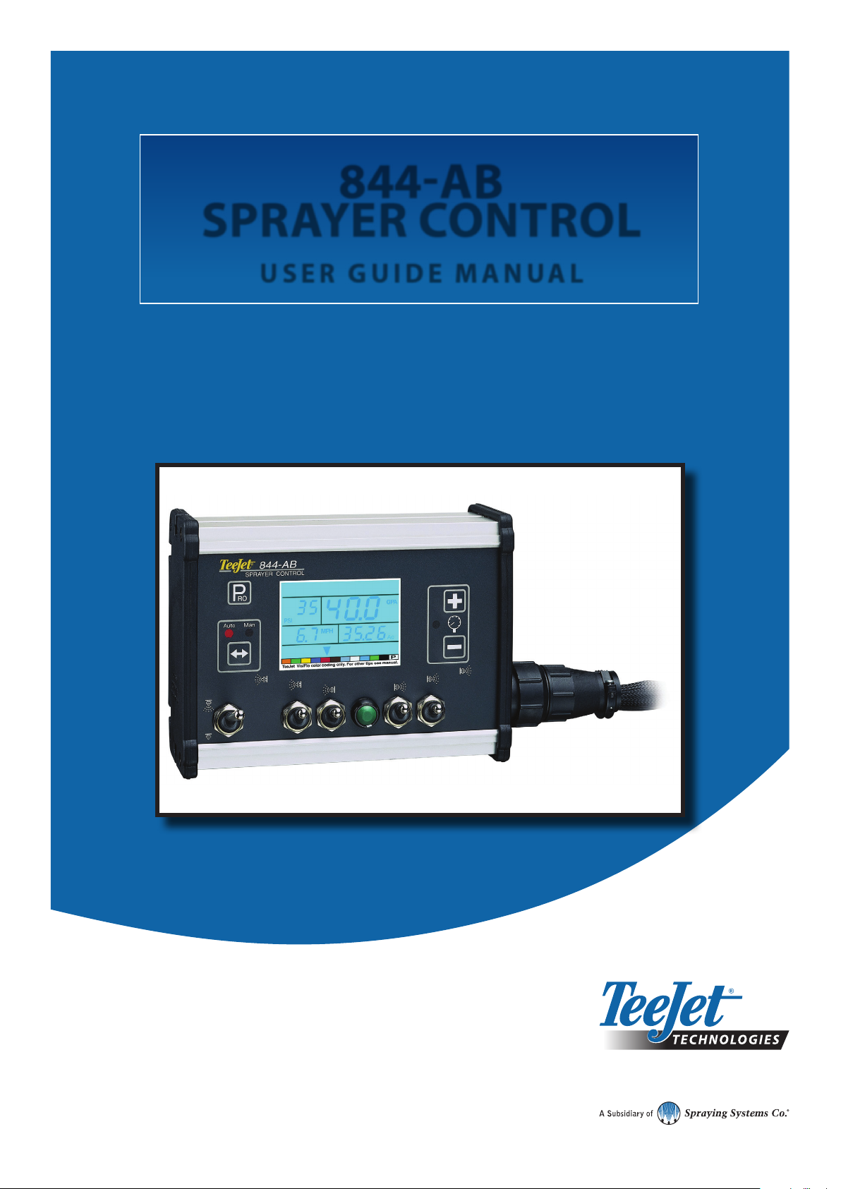
844-AB
SPRAYER CONTROL
USER GUIDE MANUAL
For use with software version 4.02.
Page 2

Copyrights
© 2013 TeeJet Technologies. All rights reserved. No part of this document or the computer programmes described in it may be reproduced,
copied, photocopied, translated, or reduced in any form or by any means, electronic or machine readable, recording or otherwise, without
prior written consent from TeeJet Technologies.
Trademarks
Unless otherwise noted, all other brand or product names are trademarks or registered trademarks of their respective companies or
organisations.
Limitation of liability
TEEJET TECHNOLOGIES PROVIDES THIS MATERIAL “AS IS” WITHOUT WARRANTY OF ANY KIND, EITHER EXPRESSED OR
IMPLIED. NO COPYRIGHT LIABILITY OR PATENT IS ASSUMED. IN NO EVENT SHALL TEEJET TECHNOLOGIES BE LIABLE FOR ANY
LOSS OF BUSINESS, LOSS OF PROFIT, LOSS OF USE OR DATA, INTERRUPTION OF BUSINESS, OR FOR INDIRECT, SPECIAL,
INCIDENTAL, OR CONSEQUENTIAL DAMAGES OF ANY KIND, EVEN IF TEEJET TECHNOLOGIES HAS BEEN ADVISED OF SUCH
DAMAGES ARISING FROM TEEJET TECHNOLOGIES SOFTWARE.
Page 3

844-AB
Table of Contents
CHAPTER 1 - INTRODUCTION 3
Power on the console .......................................................................................................................................................................................... 3
Power o the console ......................................................................................................................................................................................... 3
CHAPTER 2 - APPLICATION MODE 4
Airblast mode ......................................................................................................................................................................................................... 4
Vineyard mode ...................................................................................................................................................................................................... 4
CHAPTER 3 - OEM SETUP 4
Application type ................................................................................................................................................................................................... 4
Number of sections .............................................................................................................................................................................................. 4
Minimum voltage ................................................................................................................................................................................................. 5
Deadband ................................................................................................................................................................................................................ 5
Rotation speed ...................................................................................................................................................................................................... 5
Display stable ......................................................................................................................................................................................................... 5
Total area ................................................................................................................................................................................................................. 5
Maximum speed ................................................................................................................................................................................................... 5
Memory option ..................................................................................................................................................................................................... 6
Tank content ........................................................................................................................................................................................................... 6
CHAPTER 4 - SYSTEM SETUP 6
Units of measurement ........................................................................................................................................................................................ 6
Reset to default ..............................................................................................................................................................................7
Sensor selection .................................................................................................................................................................................................... 7
Flow meter impulses ........................................................................................................................................................................................... 7
Manual entry ..................................................................................................................................................................................7
Automatic calibration .....................................................................................................................................................................7
Pressure transducer low pressure calibration (P Ref ) .............................................................................................................................. 8
Manual entry ..................................................................................................................................................................................8
Automatic calibration .....................................................................................................................................................................8
Pressure transducer maximum rating (PHI) ............................................................................................................................................... 8
Speed sensor calibration.................................................................................................................................................................................... 9
Proximity/magnetic impulses .........................................................................................................................................................9
Automatic calibration..............................................................................................................................................................9
Manual calculation .................................................................................................................................................................9
Radar speed impulses ...................................................................................................................................................................9
Automatic calibration............................................................................................................................................................10
Manual calculation ...............................................................................................................................................................10
Simulated ground speed .................................................................................................................................................................................10
Reference ow rate per section .....................................................................................................................................................................11
1. Select section ..........................................................................................................................................................................11
2. Reference pressure .................................................................................................................................................................11
3. Reference ow ......................................................................................................................................................................... 11
Next section ................................................................................................................................................................................. 11
Regulating valve response time ....................................................................................................................................................................12
Pressure regulating mode ...............................................................................................................................................................................12
Minimum pressure setting ..............................................................................................................................................................................12
Density (Liquid specic gravity) .................................................................................................................................................................... 13
Communications ................................................................................................................................................................................................13
98-70007-EN R4
1
Page 4

844-AB
Faces per section setting (HC mode only) .................................................................................................................................................13
CHAPTER 5 - SWATH WIDTH PRESETS 14
Selecting swath preset .....................................................................................................................................................................................14
CHAPTER 6 - APPLICATION SETUP 15
Preset ow rate selection .................................................................................................................................................................................15
Nozzles per face .................................................................................................................................................................................................15
Target application rate ...................................................................................................................................................................................... 15
Calculation diagnostic .....................................................................................................................................................................................15
Adjust pressure ............................................................................................................................................................................16
Adjust speed ................................................................................................................................................................................16
Liquid density ......................................................................................................................................................................................................16
CHAPTER 7 - OPERATIONS 17
Spraying .................................................................................................................................................................................................................17
CHAPTER 8 - FEATURES 18
Boost mode...........................................................................................................................................................................................................18
Area/volume display..........................................................................................................................................................................................18
Application alarm ............................................................................................................................................................................................... 18
No ow alarm ....................................................................................................................................................................................................... 19
Automatic power down ...................................................................................................................................................................................19
Printing ...................................................................................................................................................................................................................19
2
www.teejet.com
Page 5
844-AB
CHAPTER 1 - INTRODUCTION
This user guide provides information for software version 4.02.
Make sure that all hardware components are properly installed and tested. Before starting the programming process, conrm that the console
and all sensors are working properly.
IMPORTANT! Before beginning, review the following programme guidelines that control the programming process.
To exit any Setup mode, press and hold the Programme key for 3 seconds. The inputs are stored and the computer will exit Programme
mode.
To increase the value of a programmable digit, press the Plus key. To decrease the value, press the Minus key. These keys are located
directly to the right of the display. For some programme steps, press and hold the Plus and Minus keys to quickly change the values.
Press the Plus and Minus keys once to increment/decrement the values by one unit.
Press and hold the Plus and Minus keys simultaneously to reset the value to “0” or begin automatic calibration.
Press the Programme key to advance the system to the next programme step. After the nal programme step is complete, the console will
nish the programming loop and return to the initial programming step.
System setup mode contains the options that customize the controller to the sprayer or sprayer components. These include calibration steps
and parameters that seldom change once programmed.
Application setup mode contains settings that are frequently changed (nozzle spacing, number of nozzles per boom section, density, nozzles
used and target application rate).
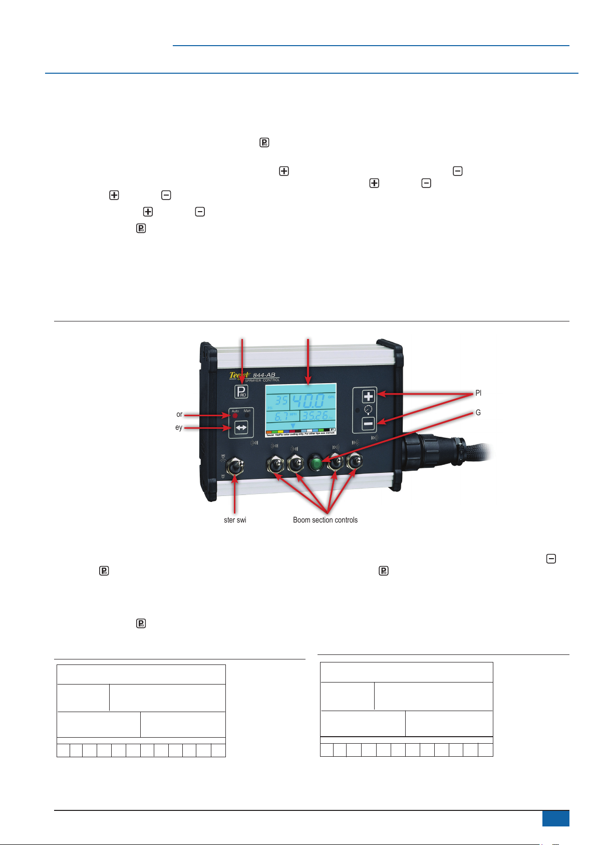
Figure 1: 844-AB console
On/programme button Display
Auto/manual mode indicator
Auto/man key
Boom section controlsMaster switch
Power on the console
The 844-AB console can be powered on by pressing the
Programme key one time. The console will initially display the
software version at the top of the screen and the serial number of the
console at the bottom of the screen. After approximately 5 seconds,
the console will enter into swath width view.
Press the Programme key to advance to normal Operations
mode.
Figure 2: Power on the console
Plus and minus keys
GREEN button
Power o the console
To power off the 844-AB console, press and release the Minus
and Programme keys simultaneously. The console will save new
information (area and volume counters) to memory before it powers
down. “Off” will be displayed on the console, followed by a 5-second
countdown, indicating the console is about to power down. The
console also has an automatic power down feature. This is described
in further detail in the Features section of this User guide.
Figure 3: Power off the console
ABL
g22
1 2 3 4 5 6 7 8 9 10 11 12
4.03
5555
OFF
5
1 2 3 4 5 6 7 8 9 10 11 12
98-70007-EN R4
3
Page 6
844-AB
CHAPTER 2 - APPLICATION MODE
The 844-AB gives the possibility of working in two different ways
to t the application. Therefore, the console should be set up and
consequent programming and working features will be dependant of
the chosen mode.
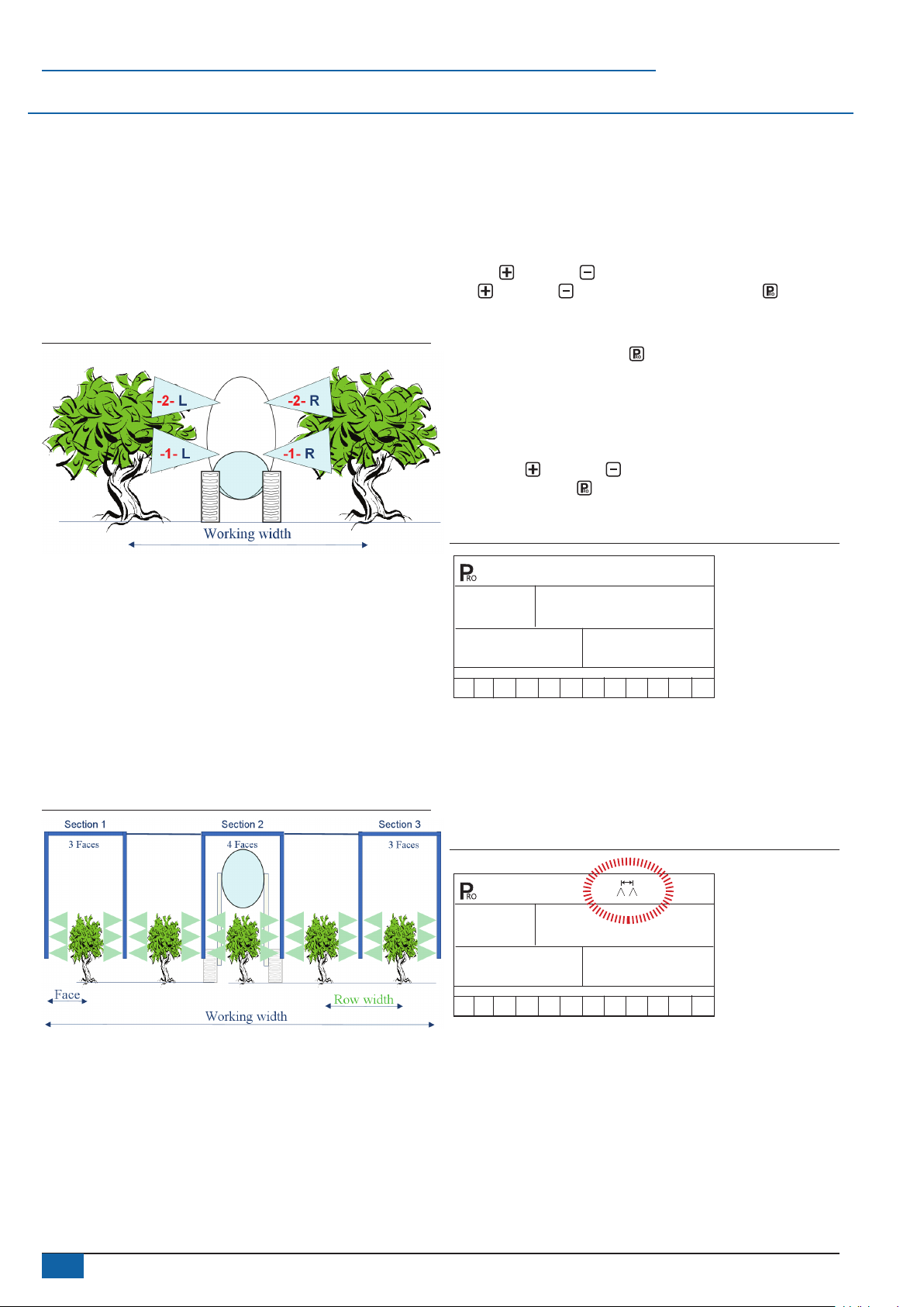
Airblast mode
This mode is designed to work with Airblast sprayers, mostly
spraying on two sides (left and right) with the possibility to switch
on or off sections in the height. The working width is dened by
the distance between two rows of trees. This mode is called AB
(airblast).
Figure 4: Airblast (AB) principle
CHAPTER 3 - OEM SETUP
OEM setup mode contains the options that customize the controller
to the sprayer or sprayer components. These include calibration
steps and parameters that will never change once programmed.
ADVISORY! OEM setup parameters (except HC/AB mode) should
not be changed unless advised by TeeJet Technologies or an
authorized dealer.
To enter System setup mode, power off the console. Press and hold
the Plus and Minus keys simultaneously. While holding the
Plus and Minus keys, also press the Programme key four
times (within 3 seconds) and then release all keys to enter OEM
setup mode.
Press and hold the Programme key for three seconds to exit OEM
setup mode. Changes will be saved to the console’s memory.
Application type
As explained above, the 844-AB is capable of working in either
Airblast (AB) or Vineyard (HC) mode.
Use the Plus and Minus keys to switch from AB to HC mode.
Press the Programme key to accept the value and advance to the
next programme step.
Figure 6: Application type
Vineyard mode
This mode is designed to work with vineyard sprayers that are
spraying horizontally. Several rows are covered and sections can be
switched on or off to adapt the working width. Each section covers
a number of faces. The working width is dened by the number of
faces and the row width.
One or more nozzles can be spraying each face. If all nozzles
spraying on a face are not equal, they should be considered as a
unique nozzle and the total ow has to be set up in the conguration
menu. But all faces have to be sprayed equally. This mode is called
HC (vineyard).
Figure 5: Vineyard (HC) principle
typ
1 2 3 4 5 6 7 8 9 10 11 12
AB
Number of sections
This will determine the maximum number of sections available on the
sprayer.
◄In AB mode, only even values are allowed (2,4,6).
◄In HC mode, all values between 1 and 7 are allowed.
Figure 7: Number of sections
nr
4
se[
1 2 3 4 5 6 7 8 9 10 11 12
4
www.teejet.com
Page 7
844-AB
Minimum voltage
This will determine the minimum voltage that can be applied to the
regulation valve. If too low, the valve won’t ne tune the dose rate. If
too high, the valve could have some unstable regulation.
Figure 8: Minimum voltage
3.5
Min
1 2 3 4 5 6 7 8 9 10 11 12
Deadband
This will determine the regulation dead band. This setting will avoid
continuous regulation when the dose rate is very close to the target
doise rate. If too low, the valve could have some unstable regulation.
If too high, the real dose rate could be far away from the target.
Figure 9: Deadband
STp
bnd
1 2 3 4 5 6 7 8 9 10 11 12
Rotation speed
This will determine the time needed by the regulation valve to travel
at maximum speed from fully close to fully open. This value must be
set according to the specications of the valve.
UOlt
1.5
Display stable
This will determine allowed tolerance percentage on the displayed
dose rate. If the difference between the real and the target dose
rates is smaller than it, the target will be displayed.
Figure 11: Display stable
5
dsp
1 2 3 4 5 6 7 8 9 10 11 12
Total area
This counter is a hidden counter that can be reset only by the
manufacturer. It shows the total area covered since last reset.
Figure 12: Total area
stbl
tot
Ha
21341
1 2 3 4 5 6 7 8 9 10 11 12
Maximum speed
This counter is a hidden counter that can be reset only by the
manufacturer. It shows the maximum speed reached by the sprayer.
Figure 13: Maximum speed
Figure 10: Rotation speed
rot
spd
1 2 3 4 5 6 7 8 9 10 11 12
6
seC
25.2
1 2 3 4 5 6 7 8 9 10 11 12
Km/h
XI6H
98-70007-EN R4
5
Page 8
844-AB
Memory option
This feature enables the user counters.
Select NO to disable this feature or YES to enable it.
Figure 14: Memory option
No
mem
1 2 3 4 5 6 7 8 9 10 11 12
CHAPTER 4 - SYSTEM SETUP
System setup mode contains the options that customize the
controller to the sprayer or sprayer components. These include
calibration steps and parameters that will rarely change once
programmed.
Table 1: System setup mode sequence
Units of measurement
Sensor selection
Flow meter impulses
Pressure transducer low pressure calibration (P Ref)
Pressure transducer maximum rating (P HI)
Speed sensor calibration*
Simulated ground speed
Reference ow rate per
section
Regulating valve response time
Pressure regulating mode
Minimum pressure setting
Density (Liquid specic gravity)
Communications
Faces per section setting, Section 1 (HC Mode only)**
Faces per section setting, Section 2 (HC Mode only)**
Faces per section setting, Section 3 (HC Mode only)**
Faces per section setting, Section 4 (HC Mode only)**
Faces per section setting, Section 5 (HC Mode only)**
Faces per section setting, Section 6 (HC Mode only)**
Faces per section setting, Section 7 (HC Mode only)**
* During speed calibration, the 844-AB will automatically sense whether a Wheel
speed or Radar speed sensor is being used.
** The number of sections available is determined within the OEM setup options.
Proximity/magnetic impulses
Radar speed impulses
Select section
Reference pressure
Reference ow
Repeat for section 2 to 12
Tank content
This feature enables a tank content counter. This counter should be
set after lling the tank and will count down according to the sprayed
volume. A zero value will disable this feature.
Figure 15: Tank content
T==1
0
1 2 3 4 5 6 7 8 9 10 11 12
To enter System setup mode, press and hold the Plus and Minus
keys simultaneously. While holding the Plus and Minus keys,
also press the Programme key twice (within 3 seconds) and then
release all keys to enter System setup mode.
Press and hold the Programme key for three seconds to exit
System setup mode. Changes will be saved to the console’s
memory.
NOTE: The 844-AB console will not automatically power down
during System setup mode. The system must be exited by
holding the Programme key for three seconds. A loss of
power to the controller during System setup mode will erase
all changes not previously saved to system memory.
Units of measurement
The 844-AB is capable of working in either US or SI (Standard
international metric). Use the Plus and Minus keys to switch
units. Press the Programme key to accept the value and advance
to the next programme step.
Figure 16: Units of measurement selection
US
1 2 3 4 5 6 7 8 9 10 11 12
Table 2: Units of measurement
US SI
Speed MPH (miles per hour) Km/h (kilometres per hour)
Flow GPM (gallons per minute) L/min (litres per minute)
Area Acres Ha (hectares)
Pressure PSI (pounds per square inch) Bar
Volume Gal (gallon) L (litre)
Speed impulses
Tree spacing Inch cm (centimetre)
Dose rate GPA (gallons per acre) L/Ha (litres per hectare)
impulses/300ft
(impulses per 300 feet)
impulses/100m
(impluses per 100 metres)
6
www.teejet.com
Page 9

844-AB
Reset to default
If units of measurement changes were made, the console will display
a message asking if programme parameters should be reset to
default before advancing to the next screen. Use the Plus or
Minus keys to select either “Yes” or “No” on the screen. Press the
Programme key to accept the value and advance to the next
programme step.
NOTE: If changes were not made to Units of measurement, this
step will be skipped and the screen will advance to Sensor
selection.
Figure 17: Reset to default
rES
YES
dEF
1 2 3 4 5 6 7 8 9 10 11 12
Sensor selection
The 844-AB can accommodate a ow meter, pressure transducer or
both. Sensor selection instructs the console which sensor is being
used on the sprayer. The default value is “FLO” (ow-based system)
using a ow meter. To maintain this setting, press the Programme
key to advance to Flow meter impulses. To change the setting to
“PRS” (pressure based system), use the Plus or Minus keys
to select “PRS”. Press the Programme key to advance to Flow
meter impulses.
NOTE: Pressure-based regulation is used only with linear nozzles.
For non-linear nozzles, ALWAYS select flow-based
regulation. Most nozzles are linear and may be used with
pressure-based regulation. ConeJet nozzles are non-linear.
If both sensors have been installed on the sprayer, this step will
determine which sensor will be used.
◄If “FLO” is selected, the ow meter will be used to control ow
and the pressure transducer will be used only to display actual
pressure.
◄If “PRS” is selected, the pressure transducer will be used
to control ow and display the actual pressure. Flow meter
signals will be ignored.
The regulation mode determines the following programme steps.
◄If “FLO” is selected, the next Setup mode screen displayed
will be the calibration step for the ow sensor (refer to Flow
meter impulses).
◄If “PRS” is selected, the next Setup mode screen displayed
will be the calibration step for the pressure transducer (ow
sensor calibration will be skipped).
Figure 18: Sensor selection
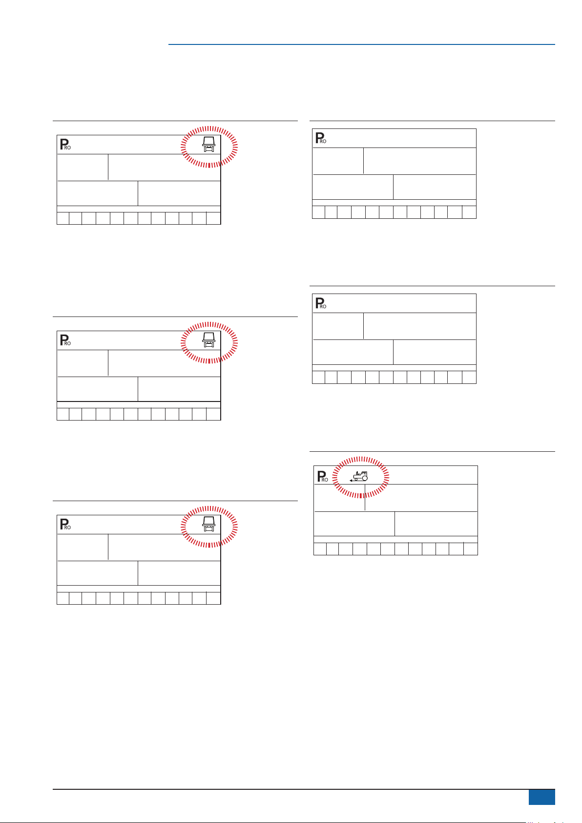
Flow meter impulses
During the Flow meter impulses step, the symbol (ow meter
turbine) will ash at the top of the console. The ow meter calibration
number can be entered manually from the factory-calibrated ow
meter pulse rate tag or an Auto calibration procedure can be
activated to determine ow meter impulses based on a known
volume of uid.
Figure 19: Flow meter impulses
650
1 2 3 4 5 6 7 8 9 10 11 12
Manual entry
Locate the factory-calibrated ow meter pulse rate tag on the ow
meter. If this varies from the default value (it usually does) of the
console, use the Plus or Minus keys to modify the value.
In some cases, larger ow meters with small calibration numbers
will include decimals for greater accuracy. To add a decimal to the
calibration number, press the Auto/man key.
Automatic calibration
To complete an automatic calibration of the ow meter, press the
Plus and Minus keys simultaneously. This will clear the
existing value and initiate the calibration procedure. “CAL” will be
displayed in the screen. This indicates that the controller is ready to
begin the calibration process.
Figure 20: Calibration procedure
CAL
0
1 2 3 4 5 6 7 8 9 10 11 12
Engage the sprayer pump. Turn the boom sections “On” and begin
spraying a known volume of uid (e.g. 400 litres). As the known
amount is sprayed, the console will count the impulses. After the
known volume has been sprayed, turn the Master switch “Off” to stop
counting impulses.
Figure 21: Calibration procedure
FLO
1 2 3 4 5 6 7 8 9 10 11 12
CAL
23
1 2 3 4 5 6 7 8 9 10 11 12
2777
98-70007-EN R4
7
Page 10

844-AB
Press the Programme key. The console will ask for the volume
that was sprayed. Use the Plus or Minus keys to adjust the
value to match the volume sprayed in litres.
Figure 22: Calibration procedure
uOL
1 2 3 4 5 6 7 8 9 10 11 12
Press the Programme key to return to the Setup mode. The
new ow meter calibration number will be displayed. To accept the
value displayed, press the Programme key again. To repeat the
calibration procedure, repeat the previous steps.
Figure 23: Calibration procedure
378
Automatic calibration
Make sure the sprayer pump is turned “Off” and there is no pressure
in the system. Press and release the Plus and Minus keys
simultaneously to activate the auto-calibration feature. The message
“MES” will be displayed. A count of “0” to “9” will appear on the lower
right portion of the screen.
Figure 25: Pressure transducer low pressure calibration
160
MES
1 2 3 4 5 6 7 8 9 10 11 12
Once the display nishes counting, a number close to 4.0 (+/- 0.2)
should be displayed. The low pressure value of the transducer is
calibrated. Press the Programme key to advance to the next step.
Figure 26: Pressure transducer low pressure calibration
3.9
9
615
1 2 3 4 5 6 7 8 9 10 11 12
Pressure transducer low pressure
calibration (P Ref)
The Pressure transducer low pressure calibration step is used to
calibrate the “0” pressure setting of the pressure transducer. The
pressure transducer used with the 844-AB uses a 4-20 mA reading
(4.0 mA represents 0 pressure).
Figure 24: Pressure transducer low pressure calibration
P
4.0
REF
1 2 3 4 5 6 7 8 9 10 11 12
Manual entry
Use the Plus or Minus keys to modify the value.
P
3.9
REF
1 2 3 4 5 6 7 8 9 10 11 12
NOTE: If a pressure transducer is not installed on the system, skip
this step by pressing the Programme key. Leave the
default value at “4.0”.
Pressure transducer maximum rating
(PHI)
The Pressure transducer maximum rating establishes the maximum
rating of the pressure transducer. This number can be found stamped
on the pressure transducer. If the transducer has a maximum rating
of 10 bar and the number is shown on the display, advance to the
next step by pressing the Programme key.
If the maximum rating is 25 bar, use the Plus or Minus keys to
change the value. Press the Programme key to advance to the
next step.
Figure 27: Pressure transducer maximum rating
8
www.teejet.com
P
Bar
3.5
Hi
1 2 3 4 5 6 7 8 9 10 11 12
NOTE: If a pressure transducer is not installed on the system, skip
this step by pressing the Programme key. Leave the
default value at “10 Bar”.
Page 11

844-AB
Speed sensor calibration
The speed sensor must be calibrated in order to provide the proper
speed and area readings. The value is determined by the number
of impulses generated by the speed sensor in 100 metres, or by
manually entering the number.
NOTE: During speed calibration, the 844-AB will automatically sense
whether a Wheel speed or Radar speed sensor is being
used.
Proximity/magnetic impulses
Figure 28: Proximity/magnet impulses
250
1 2 3 4 5 6 7 8 9 10 11 12
Automatic calibration
To automatically calibrate the speed sensor, mark a distance
of exactly 100 metres. Press the Plus and Minus keys
simultaneously to clear the contents of the display and activate
auto calibration mode. “CAL” will be displayed on the lower right
of the screen.
Figure 30: Speed sensor automatic calibration
CAL
157
1 2 3 4 5 6 7 8 9 10 11 12
NOTE: Once the automatic speed calibration process has been
activated, no other functions will operate until the console
receives speed impulses for calibration. To deactivate
automatic calibration mode, press the Plus key twice.
During the automatic calibration process, the 844-AB will
automatically sense whether a proximity/magnetic or radar ground
speed sensor is installed. If a manual entry is preferred, refer to
Manual calculation.
Manual calculation
To manually calculate the proper value for Wheel speed sensor
impulses, the circumference of the wheel to which the sensor is
mounted must be known. It can be measured by marking the tire
and measuring the distance covered as the mark makes one full
revolution. Once the number is known, use the following formula:
Figure 29: Speed sensor automatic calibration
CAL
1 2 3 4 5 6 7 8 9 10 11 12
Drive toward the initial point of the of designated 100 metres.
At the starting location, press the Plus key once to begin the
calibration process. Continue driving the course. The 844-AB
will count the impulses as the sprayer moves. The speed at
which the vehicle travels is not important. As the ending point is
reached, press the Plus key again. The console will display
the speed calibration number.
NOTES: The auto speed calibration process should take place in a
field-like environment with the sprayer tank at least half full.
It is recommended to repeat the automatic speed calibration
process at least twice and use an average of the speed
calibration numbers.
The result can be entered instead of using the automatic calibration
method. Use the Plus or Minus keys to adjust the value. Press
the Programme key to save the value and advance to the next
programme step.
Radar speed impulses
Figure 31: Radar speed sensor
rAd
1 2 3 4 5 6 7 8 9 10 11 12
250
98-70007-EN R4
9
Page 12

844-AB
Automatic calibration
To automatically calibrate the radar speed sensor, mark a distance
of exactly 100 metres. Press the Plus and Minus keys
simultaneously to clear the contents of the display and to activate
auto calibration mode. Once auto calibration mode is activated,
“RAD” will be displayed on the lower left of the screen.
Figure 32: Radar speed sensor automatic calibration
CAL
rAd
1 2 3 4 5 6 7 8 9 10 11 12
Drive toward the initial point of the designated 100 metres. At the
starting location, press the Plus key once to begin the calibration
process. Continue driving the course. The 844-AB will count the
impulses as the sprayer moves. The speed at which the vehicle
travels is not important. As the ending point is reached, press
the Plus key again. The console will display the radar speed
calibration number.
NOTES: The radar speed calibration process should take place in a
field-like environment with the sprayer tank at least half full.
It is recommended to repeat the radar speed calibration
process at least twice and use an average of the speed
calibration numbers.
Manual calculation
It is not possible to manually calculate the calibration value of a
radar. However, the value can be entered manually if it is known
from a prior calibration. To manually enter the radar calibration
value, press the Auto/man key to enter Radar mode. Once radar
calibration mode is activated, “RAD” will be displayed on the lower
left of the screen. Use the Plus or Minus keys to adjust the
value. Press the Programme key to save the value and advance
to the next programme step.
118
Simulated ground speed
Simulated ground speed allows the console and sprayer to be tested
(and actually spray water) without physically moving the sprayer.
This can and should be tested prior to any spraying activity.
The 844-AB has a low and high simulated ground speed. This allows
the operator to switch between the two to simulate a speed change
and ensure the console is regulating properly during the sprayer
checkout.
Figure 33: Simulated ground speed
SIM
9.7
1 2 3 4 5 6 7 8 9 10 11 12
SIM
9.0
1 2 3 4 5 6 7 8 9 10 11 12
To enter simulated speeds, determine whether the low or high
simulated speed is displayed on the console. Change from low to
high by pressing the Auto/man key.
Use the Plus or Minus keys to adjust the values. Press the
Auto/man key to switch to the other setting (either low or high)
and adjust the value with the Plus or Minus keys. Once both
values are entered, press the Programme key to advance to the
next step.
The console will display the simulated speed upon exiting System
Setup mode. The simulated speed will remain on the Operation
mode display until the console receives actual speed impulses. While
in Operation mode, with the Master switch in the “On” position, press
the Programme
press the Programme and Plus keys for high simulated speed.
SPD
Km/H
LO
SPD
Km/H
HIgH
and Minus keys for low simulated speed;
10
www.teejet.com
NOTES: The simulated speed feature will be deactivated once
the sprayer begins moving and the 844-AB receives actual
speed impulses. If a radar speed sensor is being used,
disconnect the radar connection from the main console. Any
movement can disable the simulated speed test due to the
sensitivity of the speed sensor.
The LOW SIMULATED SPEED will be used during the first
3 seconds after Master is set in the ON position whatever the
real forward speed. This will help starting a new row in the
best conditions.
Page 13

844-AB
Reference ow rate per section
AB mode – The ow rate for each section of the sprayer must be
input into the 844-AB console so that the necessary adjustments
can be made when boom sections are shut off. The console is
programmed to treat the left and right boom sections as symmetrical;
therefore the console treats the ow rate for the lower left section
(L1) identically to the ow rate of the lower right section (R1). The
ow rate entered for section 1 will serve as reference ow for L1 and/
or R1.
Figure 34: AB flow rate illustration
HC mode – The ow rate for a single nozzle must be input into the
844-AB console so that the necessary adjustments can be made
when boom sections are shut off. If several different nozzles are
mounted to spray on a face, they should be considered as ONE
nozzle and the total ow should be programmed.
Figure 35: HC flow rate illustration
2. Reference pressure
Before entering the reference ow, determine the pressure at which
the ow will be referenced. Use the Plus or Minus keys to
adjust the value of the pressure Bar to be used as ow reference.
The pressure selected to reference ow is not critical (any pressure
can be used). Select a pressure that is close to normal operating
pressure or select a pressure from the ow rate chart for the nozzles
being used.
Figure 37: Reference pressure
3.0
1 2 3 4 5 6 7 8 9 10 11 12
Press the Auto/man key to advance to the reference ow for
current preset section.
Bar
REF
3. Reference ow
Calculate (add) the ow rates at the referenced pressure from all
nozzles on the current preset section (left or right should be the
same). Enter the total ow rate in litres/min. for the current preset
section. Use the Plus or Minus keys to adjust the value.
1. Select section
Up to twelve preset ow congurations can be entered into the
844-AB. The presets are represented by the numbers “1-12” at the
bottom of the display. The arrow symbol indicates which preset is
being programmed.
Select which preset ow conguration to programme. Use the Plus
or Minus keys to toggle through the twelve presets.
Figure 36: Preset selection
SEL
ConF
1 2 3 4 5 6 7 8 9 10 11 12
Press the Auto/man key to setup the reference pressure and
reference ow of the selected preset.
Press the Programme key to advance to the next programme
step in System setup mode. It is not necessary to programme all
twelve presets unless they are to be used. Programme the number of
presets required. Press the Programme key again to continue in
System setup mode.
Figure 38: Reference flow (Section one entry)
3.0
Bar
-1-
1 2 3 4 5 6 7 8 9 10 11 12
Press the Auto/man key to return to the select section option.
1.36
LPm
Next section
Repeat steps 1-3 for all sections as needed.
Figure 39: Reference flow (Section two entry)
3.0
Bar
-1-
1 2 3 4 5 6 7 8 9 10 11 12
Once programming is complete for all presets, press the
Programme key to advance to the next programming step.
0.85
LPM
98-70007-EN R4
11
Page 14

844-AB
Regulating valve response time
Operating conditions may require a higher or lower response speed
for the regulating valve. To change the response time number, use
the Plus or Minus keys to increase or decrease the number.
Any number between 0.0 and 9.9 may be selected (0=Slow; 9=Fast).
The default value is 9.5. The rst digit establishes the speed for
coarse adjustments (when relatively far from the target rate). The
second digit establishes the speed for the ne adjustment (when
relatively close to the target rate). If the regulating valve is plumbed
in a bypass line, the valve speed number of 9.5 works well for most
applications.
Figure 40: Regulating valve actuating factor
(fine)
(coarse)
RE6
9.5
ACT
1 2 3 4 5 6 7 8 9 10 11 12
If the regulating valve is plumbed in the throttling position (supply
line), start with a valve speed of 3.0 and adjust the number according
to application requirements. Adjusting agitation volumes can often
assist the regulating valve operation. Press the Programme key to
accept the entry and advance to the next step.
NOTE: The speed value can be adjusted to optimize system
performance. If the valve tends to “search” for the
programmed application rate by cycling the pressure up and
down continuously, reduce the number until the “searching”
is minimal or eliminated. A higher number will increase the
valve response speed and increase the rate of adjustment.
Pressure regulating mode
Pressure regulating mode directs the 844-AB to the location of the
regulating valve plumbing. Once established, this value should not
change unless the regulating valve is physically moved to a new
plumbing location. For additional information about plumbing, refer to
the Plumbing and installation manual supplied with this kit.
The default value of bypass “BYP” indicates that the pressure
regulating valve is plumbed in a bypass line. If no changes are
necessary, press the Programme key to accept the value and
advance to the next step.
NOTE: Once the bypass mode is selected and the console is set to
“manual” mode, the pressure regulating valve should close
when the Plus key is pressed and open when the
Minus key is pressed.
If the pressure regulating valve has been plumbed into in a supply
line to the booms, it is considered a “throttling position”. Use the
Plus or Minus keys to change the displayed value to “THR”
(throttling mode). By doing this, the polarity that the console uses to
control the regulating valve will be reversed.
Figure 42: Pressure regulating mode (Throttling mode)
ThR
1 2 3 4 5 6 7 8 9 10 11 12
NOTE: Once the throttling mode is selected and the console is set
to “manual” mode, the pressure regulating valve should open
when the Plus key is pressed and close when the
Minus key is pressed.
Press the Programme key to accept the entry and advance to the
next step.
Minimum pressure setting
The Minimum pressure setting establishes the minimum pressure
the sprayer will regulate. When the vehicle slows down, the control
system will sometimes regulate the pressure so low that it falls below
the manufacturer’s recommended pressure for the spray nozzle. It
may also reduce system ow to the point where the ow meter will
stall.
To avoid these situations, the 844-AB can be programmed to avoid
regulating below the pressure established with this setting. If the
default setting of 0.7 bar is used, the pressure will not fall below 0.7
bar while spraying in automatic mode.
Use the Plus or Minus keys to adjust the value. Press the
Programme key to advance to the next programme step.
Figure 43: Minimum pressure setting
Figure 41: Pressure regulating mode (Bypass mode)
BYP
1 2 3 4 5 6 7 8 9 10 11 12
12
www.teejet.com
0.7
Bar
MiN
1 2 3 4 5 6 7 8 9 10 11 12
PRS
Page 15

844-AB
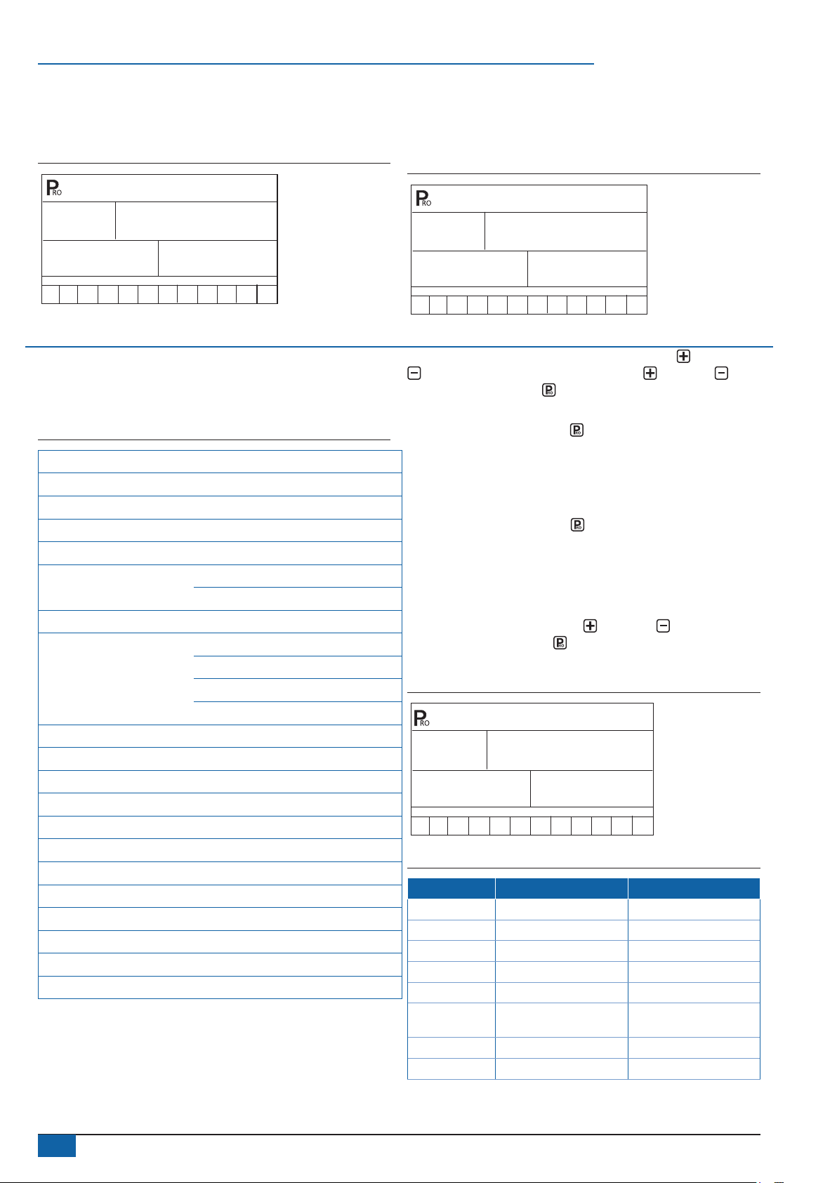
Density (Liquid specic gravity)
The default value of “1.00” corresponds with the specic gravity of
water and is correct for most pesticide applications. Some spray
solutions, such as fertiliser, have different densities. If such a
material is being used, a new value should replace the default.
Figure 44: Density display
1.28
1 2 3 4 5 6 7 8 9 10 11 12
Use the Plus or Minus keys to change the value. Press the
Plus and Minus keys simultaneously to clear the value to
“0”. Press the Programme key to accept the value and advance
to the next step.
The following chart will help determine the density of other solutions.
Table 3: Density settings
Weight of solution per
7.0 lb 0.84 Kg 0.84
8.0 lb 0.96 Kg 0.96
8.34 lb (water) 1.00 Kg 1.00
10.0 lb 1.20 Kg 1.20
10.65 lb (28% N) 1.28 Kg 1.28
10.85 lb (30% N) 1.30 Kg 1.30
11.0 lb 1.32 Kg 1.32
12.0 lb 1.44 Kg 1.44
14.0 lb 1.68 Kg 1.68
If the solution is not identied on the chart (above), the Specic
gravity can be calculated as follows:
• Water weighs 1 Kg/L.
• To activate the specic gravity number while in the Application
setup mode, press the Auto/man key so “D” is displayed on
the top of the screen. All calculations will use the specic gravity
entered during this step. To remove the “D” press the
Auto/man key again. Once the “D” is not displayed, all
calculations will use the specic gravity of water (1.00)
regardless of whether another density was programmed or not.
Refer to Application setup mode for additional information.
Specic GravityGallon Litre
Communications
If the 844-AB has been upgraded and is communications compatible,
a variety of communications options can be entered. Choices
available include the default of no communications “no com”,
contractor printing ”cnt prt” , user printing “usr prt”, global positioning
system communications capability “gps”, downloading to a pc ‘onthe-go’ capability “log” or PC link “pc” (not used).
Figure 45: Communications settings
COM
1 2 3 4 5 6 7 8 9 10 11 12
If the 844-AB has not been upgraded with the communication
package, no change is required. If a change is necessary, press the
Plus or Minus keys to select the type of communication used.
Press the Programme key to accept the value and advance to the
beginning of System Setup mode.
Faces per section setting (HC mode only)
As HC mode calculates working width based on the number of faces
sprayed by each section. Additional steps are required to setup these
values.
Figure 46: Section 1 Faces settings
se[
1
1 2 3 4 5 6 7 8 9 10 11 12
Use the Plus or Minus keys to adjust the value. This step will
repeat for each section. Press the Programme key to advance
to the next section. The number of sections available is determined
within the OEM setup options.
Figure 47: Section 7 faces settings
se[
1
fA[e
1
7
1 2 3 4 5 6 7 8 9 10 11 12
After cycling through all sections, press the Programme key to
advance and return to the rst programme step.
fA[e
98-70007-EN R4
13
Page 16

844-AB
CHAPTER 5 - SWATH WIDTH PRESETS
The 844-AB can be programmed with up to 6 swath widths. This
allows the operator to easily change from one swath to another
during application. (This is essential when spraying orchards that
have varying swath widths.)
To enter Swath width presets mode, press and hold the GREEN
button for 3 seconds. The swath width setting screen for preset
number 1 will be displayed. The swath width is displayed on the
lower right of the console (measured in metres for SI [metric] units).
Figure 48: Entering swath width presets
Selecting swath preset
Once the swath widths are programmed, select the swath width to
be used by pressing the GREEN button during Operations mode.
The console will display which swath preset is being used. If the
preset displayed is correct, press the Programme key to return to
Operations mode.
Figure 50: Swath width selection
11.0
11.0
1 2 3 4 5 6 7 8 9 10 11 12
Use the Plus and Minus keys to adjust the value for the rst
swath preset. Press the GREEN button or the Programme key
to advance to the next swath preset. Use the Plus and Minus
keys to adjust the swath value. Continue this process through the six
possible presets. If all six presets are not required, enter values only
for the necessary number of presets. All others should be set to “0”.
Values set to “0” will not be available for selection. Once the presets
have been entered, press the GREEN button or the Programme
key to return to the Operations mode.
Figure 49: Entering swath width
13.0
1 2 3 4 5 6 7 8 9 10 11 12
1 2 3 4 5 6 7 8 9 10 11 12
Should a different swath preset be desired, press the GREEN button
again to advance to the next swath selection. Continue to press the
GREEN button until the appropriate swath preset is displayed. Press
the Programme key to select the preset and return to Operations
mode.
NOTE: When toggling through swath width selections, only those
with presets programmed will be displayed (if presents
5 and 6 are set to “0”, they will not be displayed).
14
www.teejet.com
Page 17

CHAPTER 6 - APPLICATION SETUP
Application Setup mode contains the most frequently changed setup
parameters (target application rate and nozzles used). TeeJet has
added this separate setup mode to speed the programming process
when minor changes are made during operation (e.g., changing
orchards, switching nozzles, changing crops, etc.).
To enter Application Setup mode, while in Operations mode press the
Programme key twice (within 3 seconds). One press of the
Programme key will display “PRO USER,” indicating the console
is about to enter Application Setup mode. If the Programme key is
pressed inadvertently, the console will display “PRO USER” for three
seconds before returning to Operations mode. Pressing the
Programme key a second time within 3 seconds will enter
Application Setup mode.
Figure 51: Entering application setup
844-AB
Nozzles per face
NOTE: If AB mode has been selected, this step will be skipped and
the screen will advance to Target application rate step.
The nozzle symbol will ash during the Nozzle per Face step. Press
the Plus or Minus keys to adjust the value. Pressing the
Plus or Minus keys simultaneously will clear the value to “0”.
Press the Programme key to advance to the next step.
Figure 53: Nozzles per face
6.8
6.9
Bar
90.0
Km/H
L/Ha
4
PRO
USER
1 2 3 4 5 6 7 8 9 10 11 12
Table 4: Application setup mode sequence
Preset ow rate selection
Nozzles per face
Target application rate
Calculation diagnostic
Liquid density
Preset ow rate selection
The symbol will ash at the bottom of the screen. The numbers
1-12, also located at the bottom of the screen, represent the 12
preset dose rates. Use the Plus and Minus keys to toggle
through the presets and select the appropriate one for application.
Press the Programme key to advance to the next step.
Figure 52: Preset flow rate selection
4.1
Bar
90.0
Adjust pressure
Adjust speed
L/Ha
1 2 3 4 5 6 7 8 9 10 11 12
Target application rate
The application rate units (e.g., L/Ha) will ash during the Target
application rate step. Press the Plus or Minus keys to adjust
the value of the target application rate. Pressing the Plus and
Minus keys simultaneously will clear the value to “0”. Press the
Programme key to advance to the next step.
Figure 54: Target application rate
6.8
Bar
6.9 4
1 2 3 4 5 6 7 8 9 10 11 12
Km/H
90.0
L/Ha
Calculation diagnostic
NOTE: This step is used for diagnostic purposes only. It has no
affect on the operation of the 844-AB.
This diagnostic tool will allow the operator to adjust the indicated
pressure to see what affect, if any, it would have on operating speed.
The operator can also adjust the speed to see what pressure is
required to maintain the target application rate. This process will
help determine if the correct nozzle conguration was chosen for
the application. While in the calculation step, either the pressure or
speed units will ash.
8.7 4
1 2 3 4 5 6 7 8 9 10 11 12
Km/H
98-70007-EN R4
15
Page 18

844-AB
Adjust pressure
If an approximate operating pressure is known, use the Plus or
Minus keys to adjust the value. The 844-AB will determine what
operating speed is required to achieve the target application rate
at the entered pressure. If the speed is too high, a set of smaller
nozzles is necessary. If the speed is too low, a set of larger nozzles
is necessary.
Figure 55: Adjust pressure
2.8
Bar
6.8
1 2 3 4 5 6 7 8 9 10 11 12
Km/H
70.0
L/Ha
Adjust speed
If an adjustment to the speed setting is required, press the
Programme key once. The speed units will ash. Use the Plus
or Minus keys to adjust the speed to the desired value. The 844AB will calculate the required pressure to maintain target application
rate at the entered speed. If the pressure is too high, a set of larger
nozzles is necessary or the speed must decrease. If the pressure
is too low, a set of smaller nozzles is necessary or the speed must
increase.
Figure 56: Adjust speed
NOTE: If a liquid with a density other than water will be sprayed,
and that density was programmed into the Specific gravity
(Density) step during System setup mode, the “D” symbol
must be selected during Application setup mode to activate
the alternate density.
Press the Auto/man key during Application setup mode to
activate the alternate density. A “D” will be displayed at the
top of the console to indicate the alternate density is active.
This must be displayed so that all calculations will use the
alternate density during operations. If the “D” is not at the top
of the display, calculations will be based on water (1.00).
Figure 58: Liquid density
5.7
Bar
10.0
1 2 3 4 5 6 7 8 9 10 11 12
After performing the calculations, advance to the beginning of
Application Setup mode to make changes by pressing the
Programme key. If no changes are necessary then Application
setup mode is complete. Press and hold the Programme key for
three seconds. Changes to Application setup mode will be stored in
the console’s memory.
Km/H
70.0
L/Ha
5.2
Bar
10.0
1 2 3 4 5 6 7 8 9 10 11 12
Km/H
70.0
L/Ha
Liquid density
To activate the Liquid density setting, press the Auto/man key.
The D symbol will be displayed at the top of the screen. The Liquid
Density that is programmed into the console will also be displayed.
To change density, press the Plus
Programme key to accept the changes and return to the current
application setup step. The calculations will use the Specic gravity
(Density).
To revert back to the calculation based on spraying water, press the
Auto/man key.
Figure 57: Liquid density
or Minus keys. Press the
NOTE: The 844-AB console will not automatically power down
during Application setup mode. The system must be exited
by holding the Programme key for three seconds. A loss
of power to the controller during Application setup mode will
erase all changes not saved to system memory.
1.28
1 2 3 4 5 6 7 8 9 10 11 12
16
www.teejet.com
Page 19

CHAPTER 7 - OPERATIONS
Before operating, check connections related to the Sprayer control
assembly. The sensors should be checked to ensure the console
receives uninterrupted signals.
IMPORTANT! When work occurs around a sprayer/farm chemicals,
wear protective clothing and eye wear. Partially fill the
sprayer tank with water to flush the system. Perform an
inspection of the spray nozzles to ensure they are spraying
the correct pattern.
The Master Boom Switch should be in the “Off” position. Perform the
following steps prior to application:
1. Ensure the tank shut-off valve is “Open”.
2. Start the engine, engage the pump and set the RPM to the level
to be used during application.
3. Power on the 844-AB by pressing the Programme key.
4. Ensure the preset reference ow number matches the nozzles
being used.
5. Ensure the console recognizes simulated speed. If the simulated
speed has been disabled due to movement of the sprayer,
press the Programme and Plus keys to activate the high
simulated speed. Press the Programme and Minus keys to
activate the low simulated speed.
Figure 59: Simulated speed (Low)
SIM
9.7
1 2 3 4 5 6 7 8 9 10 11 12
6. Power “ON” the toggle switches for each spray boom section.
7. Press the Auto/man key so the red LED light indicates “MAN”
mode.
8. Toggle the Master boom switch to “ON”.
9. Adjust the pressure with the Plus and Minus keys. The
pressure should increase with the Plus key and decrease with
the Minus key. During adjustment, the sprayer will be active
so spray nozzle performance can be visually monitored.
10. Press the Auto/man key so the red LED light indicates “Auto”
mode. The 844-AB should adjust to the appropriate target
application rate for the simulated speed.
11. Press the Programme and Plus keys simultaneously
during spraying to switch the console to “high” simulated speed.
The 844-AB should adjust to the appropriate target application
rate for the simulated speed.
12. Press the Programme and Minus keys simultaneously
during spraying to switch the console to “low” simulated speed.
The 844-AB should adjust to the appropriate target application
rate for the simulated speed.
Toggle the Master boom switch to “OFF” to stop spraying.
SPD
Km/H
LO
844-AB
NOTE: It is recommended that the entire sprayer be calibrated in
preparation for operation and to diagnose wear to spray
nozzles. Worn nozzles can contribute to costly chemical
waste and inaccurate spraying regardless of sprayer control
use. Calibration is important to obtain the benefits associated
with computerized sprayer control.
Spraying
Fill the sprayer tank and mix the chemical(s). The application rate
should already be programmed, as well as the spray nozzle size.
1. Power on the 844-AB by pressing the Programme key.
2. Toggle the appropriate individual boom switches to the “ON”
position.
3. Press the Auto/man key so the red LED light indicates “Auto”
mode.
4. With the Master boom switch in the “OFF” position, the target
application rate and the target symbol will be displayed on the
console.
5. With the Master boom switch in the “ON” position, the actual
application rate will be displayed and the target symbol will no
longer appear. The console will display the actual application
rate, vehicle speed, application area covered/total volume
applied and pressure (if a pressure transducer has been
installed).
6. Turn the Master boom switch to the “On” position as the area to
apply is entered. Spraying will begin.
7. Maintain vehicle speed for spraying. Moderate changes in
vehicle speed will not affect the application rate (changes are
compensated by automatic pressure increases or decreases).
To stop spraying, turn the Master boom switch to the “OFF” position.
Alarm warnings may occur momentarily while the pressure regulating
valve searches for a new setting (i.e. after the close of a boom
section or other changes in normal operation). However, if the alarm
continues for a longer time, the valve may have reached its limit and
the system will be unable to regulate ow correctly.
98-70007-EN R4
17
Page 20

844-AB
CHAPTER 8 - FEATURES
Boost mode
Increased or decreased chemical application may be required during
certain areas of application. The Plus and Minus keys allow for
easy adjustment. Boost mode can be activated while spraying during
“Auto” mode by pressing either the Plus or Minus keys once.
With each subsequent press of the Plus key, the application rate
will increase by 10%. With each subsequent press of the Minus
key, the application rate will decrease by 10%.
If the Plus or Minus key is pressed inadvertently during
operation, a delay of three seconds will deactivate Boost mode.
Succeeding presses will change the target rate in 10% increments to
a maximum of +/- 90% of the target rate.
Example: To increase the application rate by 10%, press the
Plus key once to activate Boost mode. Press the
Plus key again to initiate a 10% increase. To decrease
the application rate by 10%, press the Minus key once to
activate Boost mode. Press the Minus key again to initiate
a 10% decrease.
Application rate changes are monitored on the display as they occur.
The console will display “UP 10”, “UP 20”, “DN 20”, “DN 30”, etc. for
approximately three seconds before returning to actual application
rates.
Figure 60: Boost mode
Area/volume display
The 844-AB records application area and measures the total volume
applied while the Master boom switch is in the “ON” position. The
area counter measures treated hectares and is dependent on
the value programmed for swath width. The volume measured is
dependent on ow meter impulses and is available on ow-based
models only.
The console will alternately display the treated area sprayed and
the total volume applied (litres) since the last time the area counter/
volume measure was cleared.
To clear the area counter/volume measure, press and hold the
Plus and Minus keys simultaneously for three seconds. The
area/volume measure can only be cleared during Operations mode
with the Master boom switch in the “Off” position.
Figure 61: Area/volume display
3.1
Bar
5.6
1 2 3 4 5 6 7 8 9 10 11 12
Km/H
60.0
1.507
L/Ha
Ha
UP
Bar
32
1 2 3 4 5 6 7 8 9 10 11 12
To return the application rate to the original target rate, use the
Plus or Minus keys individually to increase/decrease the
rate in 10% increments, or press the Plus and Minus keys
simultaneously to return to the programmed target application rate.
NOTE: During boost mode, the target symbol will flash at the top
of the console to indicate the sprayer is not operating at the
target application rate.
Km/H
70
0.166
L/Ha
Ha
NOTES: The area counter/volume measure works only when the
Master boom switch is in the “On” position.
If a pressure-based controller is being used, the volume
feature will be disabled. The total area will be displayed at
all times.
Application alarm
If the 844-AB detects a continuous discrepancy of 10% or more
between the Target application rate and the Actual application rate,
the application rate units (L/Ha) will ash in the display window. This
will alert the operator to a problem with the plumbing, operation or
programming.
Figure 62: Application alarm
3.1
Bar
4.8
1 2 3 4 5 6 7 8 9 10 11 12
Km/H
Err
.545
L/Ha
Ha
18
www.teejet.com
Page 21

No ow alarm
If the 844-AB stops receiving impulses from the ow meter, the
turbine symbol will ash at the top of the display. This indicates that
there is a problem with the ow meter or elsewhere in the system.
This alarm will occur only when the Master boom switch and at least
one boom toggle switch are set to the “ON” position.
Figure 63: No flow alarm
844-AB
0.00
1 2 3 4 5 6 7 8 9 10 11 12
5.8
Bar
Km/H
0.00
2.223
L/Ha
Ha
Automatic power down
The 844-AB console is designed to power off after 10 minutes of
inactivity. This feature prevents the console from draining the battery
on the sprayer if the operator inadvertently leaves the console
powered on for an extended period. This feature is only enabled
when the Master boom switch is turned “Off” and the console is not
receiving inputs from any of the sensors (the sprayer is inactive).
To manually power down the console, refer to Power off the console.
NOTE: The Automatic power down feature will be disabled any time
the console enters into any programme mode. Programme
modes must be exited first before powering down to ensure
all information is saved to the console’s memory.
Printing
The printing feature is only available on 844-AB consoles that have
been upgraded with the communications package. The 844-AB
communications package is available through authorized TeeJet
Technologies suppliers.
The printout generated by the 844-AB contains information collected
from 844-AB memory. To ready the 844-AB for printing, refer to
Communications in System Setup mode and select either “user prt”
or “cn prt” depending on which report is desired. Exit the mode by
pressing and holding the Programme key for three seconds.
Connect a standard serial port printer to the 844-AB console and
make sure that the printer LED’s are lit, indicating that the printer
has power. Ensure that the console is in Operations mode and the
Master boom switch is set to “Off”. Press and hold the Minus key
for three seconds to begin printing. To reset the values to zero, press
and hold the Plus and Minus keys simultaneously for three
seconds.
NOTE: Printing is available only to those 844-AB consoles that have
been upgraded with the COMMUNICATIONS PACKAGE.
To determine 844-AB console printing capabilities, examine
the left end plate of the console. A communications-ready
console will have an RS-232 pin connector attached to the
left end plate. If the end plate has no connector, the console
has not been upgraded and cannot print.
98-70007-EN R4
19
Page 22

Page 23

Page 24

844AB
SPRAYER CONTROL
USER GUIDE MANUAL
TeeJet Aabybro
Mølhavevej 2
DK 9440 Aabybro
Danmark
www.teejet.com
98-70007-EN R4 English/International
© TeeJet Technologies 2013
 Loading...