

Page 1

Installation Instructions
4-channel Stereo Satellite TV Converter
®
TechniNet
Order No.:
0004/5900 TechniNet A
0004/5901 TechniNet B
0004/5902 TechniNet C
0004/5910 TechniNet A-VPS
0004/5911 TechniNet B-VPS
0004/5912 TechniNet C-VPS
Page 2

TECHNINET is designed to convert satellite IF (Intermediate Frequency) signals into VHFcompatible signals (Version A:EO2...EO4, SO2...SO4, Version B:SO4...S10, EO5...E12,
S11...S20, Version C: E21...E37, S21...S41). The unit is fully programmable, compatible with
neighbouring channels, and converts stereo/dual tone signals in accordance with the dual
sound carrier protocol. In the VPS versions, an integrated line data decoder evaluates the
PDC/VPS data broadcast by many stations/providers. The units are thus in a position to recognise varying sound modes received from the broadcaster (mono, stereo, dual channel
sound), and to automatically activate the appropriate code frequencies within the PAL signal.
Channel 1 is supplied by a separate input, E1. An integrated distribution field is available at
input E2, which distributes the signals of one level to channels 2, 3 and 4. This signal is then
subject to damping by 9 dB before being made available for further distribution at output A.
Both Satellite-IF inputs are provided with current appropriate to an LNB (13V, 300 mA max.)
It is possible to loop an external decoder through into channel 4, using the Sub-D connector.
The appropriate connection cable for Sub-D-SCART is available under Order no. 0000/3613.
The output level of the individual channels can be adjusted by means of the respective controls (approx. 80..100 dBµV.
Data remains in memory even if there is a power failure.
Installation:
Please ensure there is enough space to provide adequate ventilation. Install the base station in a room in which a maximum ambient temperature
of 55° C. is not exceeded at any time, even at the height of summer.
Mount the unit(s) in an upright position next to each other on a wall surface, or use the wallmounted housing, which is obtainable as an accessory. Ensure that units are placed
at a distance of at least 4 cm from each other.
Where several units are to be installed together, the relevant ouputs must be connected by
means of multiple connectors (or by means of inversely switched BK distributors). This will
result in a certain level of collective damping, which may make it necessary to include a suitable BK amplifier in the signal path. However, amplifier output levels in excess of 110 dBµV
are not recommended.
The IF in-/outputs can be switched as required, depending on programme allocations. Pay
attention to the acceptable range of levels at the inputs.
NOTE:
In order to avoid damage to the TechniNet units, the installation should be
properly grounded (earthed) before it is switched on.
Preliminary Settings:
All four channels are preprogrammed to default settings at the factory, in order to provide a
defined starting point for the user. Pre-programming is carried out in relation to ASTRA, and
with reference to an LNB with a LOF of 9.75 GHz. The following settings are programmed at
the factory:
- audio bandwidth 130 kHz - video level high
- volume 0 dB - internal signal path (channel 4)
- adaptive de-emphasis - VPS versions: VPS auto on
- audio A 7.02 MHz, B 7.20 MHz - output offset 0 kHz
Page 3

1 1509 E 02 E 05 S21 Zweiton Eurosport (G)
2 1744 E 03 E 07 S37 stereo ARD Germany
3 1214 E 04 E 09 E21 stereo ZDF Germany
4 1891 S 04 E 11 E37 stereo n-tv Germany
Programming block:
Programming is entered via the keyboard.In order to prevent an unintentional change in stored data, the keyboard is electronically blocked once programming has been completed.
This programming block can be idsabled by pressing both arrow keys simultaneously for approx. 4 seconds. Once the red display starts to blink, you have approx. 3 seconds in which to
press both the "+" and "-" keys, which will enable the programming mode (display of channel
1)
Programming:
Switch on the current supply, and enable (unblock) the keyboard. The number of the channel
selected appears in the red display, the parameters selected appear in the green display.
The parameters are set by means of the "+" and "-" keys. The arrow keys are used to move
on to the next parameter. The "M" key is used to store the programmed values, and to move
on to the next channel.
When you have selected channel 4, pressing the "M" key will result in programmed values
being stored in memory, and you will exit the programming mode (red display shows "-").
The following parameters can be called up successively for each channel, and altered:
Parameter Available settings Display
Output channel S04...S10 S xx
(Version A / Version B / Version C) E02...E04 E05...E12 S21...S41 C xx
S02...S04 S11...S20 E21...E37 S xx
0
Output channel offset + / - 16 *62,5 kHz
xx
Input frequency 950...2050 MHz xxxx
0 0
0-0
-
-
-
-
, B
0
-
-
-0-
Video amplification high UU
low UU
VPS-Auto on UPS
(only for VPS-Versions) off UPS
Audio mode dual channel sound
stereo
mono A, mono B A
Sound sub-carrier frequency 5.50...8.70 MHz Ax.xx , Bx.xx
Audio bandwhidth 130 kHz =130
280 kHz =280
380 kHz =380
600 kHz =600
Audio de emphasis adaptiv AD
50µs 50
75µs 75
U
U
J17 J 17
Audio level +3...-6 dB in 1dB steps x DB
Signal path (only channel 4) internal INT
for decoder loop-through external DEC
Page 4
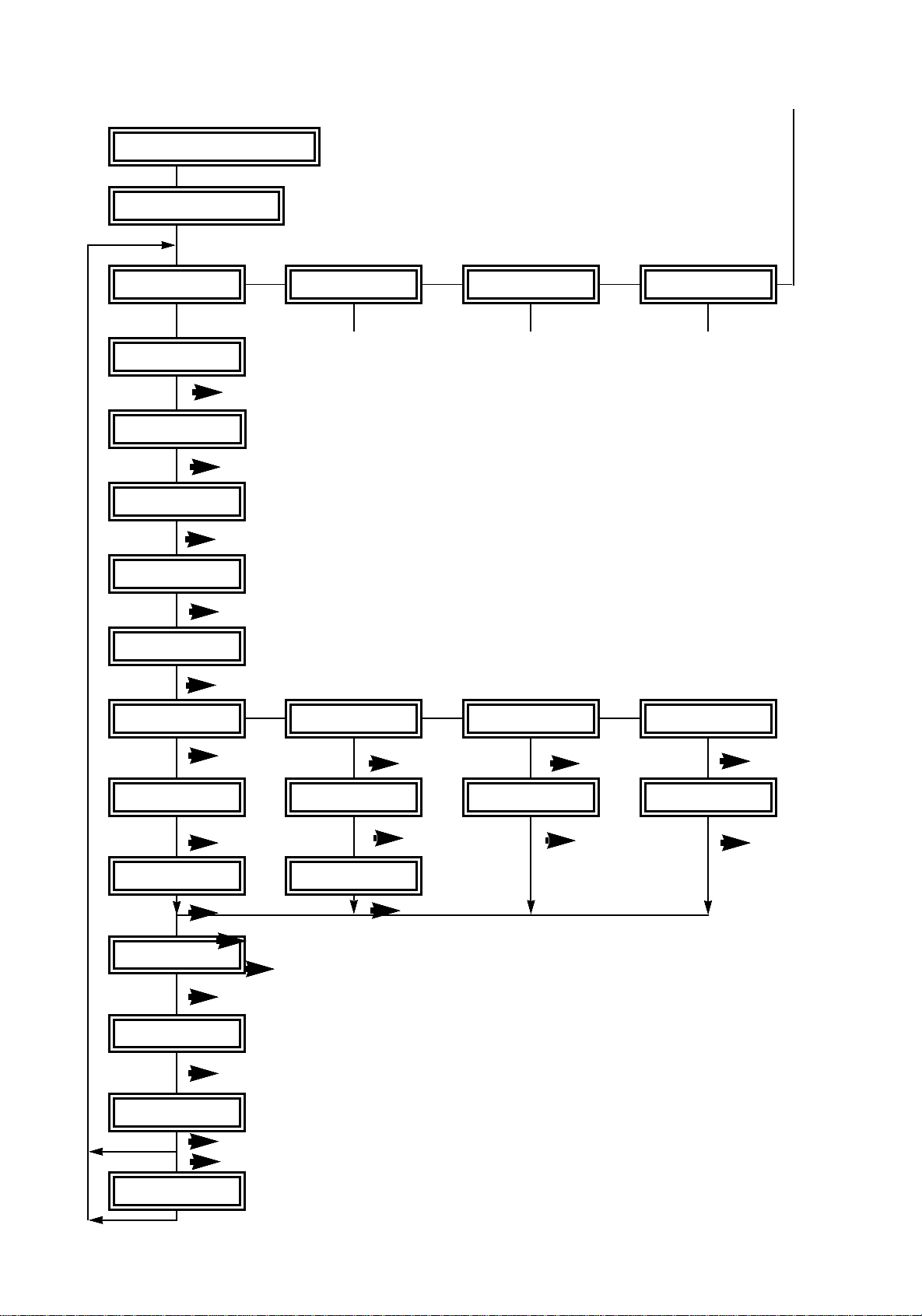
Keyboard disable (block)
Keyboard enable
Channel 1
Output channel
·
Output channell offset
·
Input frequency
·
Video Level
·
VPS-Auto
·
“M”
Channel 2 Channel 3 Channel 4
+/-
+/-
+/-
+/-
(in versions without VPS becomes)
+/-
“M” “M”
“M”
Dual channel sound
· · ·
Sound Frequency 1
Sound Frequency 2
· ·
Bandwidth Sound
·
De emphasis Sound
·
Sound Level
·
·
Video path (ch 4)
+/-
+/- +/- +/-
Stereo Sound Mono A Sound Mono B
Frequency Left Frequency Frequency
· · ··
Frequency Right
+/- +/-
+/-
+/-
+/-
+/-
·
+/-
Page 5

Out ut channels that are already configured in terms of other channel cannot be rogram
med in the channel you are currently working on, and will be automatically ignored (blinking
display).
The AFC is inactive while the input frequency is being selected, AFC is activated again when
you exit the programming level.
Dual channel sound: the sound sub-carrier with the lower frequnecy is automatically allocated to sound channel 1 (audio 1) in the PAL signal.
Stereo sound: when the sound sub-carrier for the left channel (e.g. 7.02 MHz) is selected,
the sub-carrier for the right channel is automatically selected at the same time by the addition of 180 kHz to the frequency (in this example, 7.20 MHz). This will usually be correct. However, where necessary, the right channel sound sub-carrier can be selected specifically in
the next programming step.
VPS-Auto function - in TechniNet VPS
If the VPS is switched on, and the decoder recognizes valid PDC/VPS data, the audio mode
established by the decoder will have precedence over the programmed mode. In this case,
the decimal point of the channel number display will be activated.
If no VPS data is being transmitted on this channel, or if the decoder does not recognize the
data, or when the automatic function is switched off, the programmed audio mode will be effective.
The decimal point of the left-hand (green) display will light up while you are on the menu
step Aidio Mode, if the automatic function is switched on (independent of the signal received).
The displays and settings relate only to the channel currently selected.
Example of a programming procedure:
Channel 1, Programme ARTE on Channel SO4, with dual channel sound German/French
1. Switch on the power supply.
2. Enable keyboard operation as described under "Programme blocking"
3. The display will show the setting of the selected output channel of channel 1. Use the "+" and "-
" keys to select the required output channel (S 04).
4. Press the key
normal circumstances, this setting should be retained as 0 (
5. Press the key
6. Press the key . Use the + or - keys to adjust the video amplification, e.g. for ASTRA it is al-
ways "high" (
7. Only for VPS version: Press the key . Use the + or - keys to switch the VPS auto function
on or off, in this example set to off (dual channel sound fixed) (UPS-)
8. Press the key . Use the + or - keys to select the desired audio mode, in the example dual
channel sound (o_o).
9. Press the key . Use the + or - keys to select the desired Sound 1 frequency, in the example
7.02 MHz for German (A7.02)
10. Press the key . Use the + or - keys to select the desired Sound 2 frequency, in the example
7.38 MHz for French (B7.38).
11. You can now press the key several times in order to select the remaining parameters,
such as bandwidth (130 kHz), de-emphasis (adaptive) and volume, and can use the + or - keys
appropriately to make your selection, or to check on your existing settings.
12. Pressing the "M" key at any stage of the programming procedure will take you to the next chan-
nel path. Simultaneously, the programmed values for the completed channel path will be automatically stored in memory.
Settings:
Set the audio and video levels in such a way that a simliar sound volume and picture quality is achieved for all programmes selected and set.
The output levels of the channel paths can be adjusted on the underside of the TechniNet unit within a
range of 20 dB for each channel.
Set all output levels of the base station to the same value.
. Use the + or - keys you can select the offset of the output channel. Under
o O
).
..
Use the + or - keys to select the desired satellite IF input frequency (
--
UU
)
-964
).
Page 6

Dimensions (H x W x D) 463 mm x 102 mm x 294 mm
Voltage 230V, +6% -10%, 50 Hz
Power consumption < 50 W
Permissible ambient temperature 0 - 55° C.
Weight approx. 5 kg
LNB feeder current approx. 13V, max. 300 mA (to each of E1 and E2)
Certification CE
Receiver section:
Input frequency range 950..2050 MHz
Tuning PLL frequency synthesizer, 1 MHz steps, AFC
Input level range E1 50..79 dBµV
Input level range E2 59..88 dBµV
Input impedance 75 Ohm
Bandwidth 2. IF 27 MHz
Video stroke 2 levels, switchable
Signal-to-noise, weighted > 46 dB
Audio:
Tuning range sound sub-carrier 5.50..8.70 MHz (on 10 kHz grid)
Bandwidth HF 130 kHz, 280 kHz, 380 kHz, 600 kHz
De-emphasis 50µs, 75µs, J17, adaptiv (compatible to Panda-Wegener 1)
Bandwidth LF 50 Hz..14 kHz (-3dB)
Distortion < 0.5% at Ua max., 1 kHz
Signal-to-Noise (A) > 60 dB
Crosstalk damping > 50 dB
Decoder interface Channel 4:
Connector: SUB D, 15 pin
Outputs FBAS 1 Vss/ 75 Ohm at 1.5 MHz reference frequency
Bandwidth 5 MHz (3 dB)
De-emphasis CCIR Rec. 405-1
Basic band 1 Vss/ 75 Ohm
Audio > 900 mVoff into R > 10 kOhm, adjustable +3/ -6 dB
Inputs FBAS 1 Vss /75 Ohm sync. negative
Audio 1 Voff into R< 10 kOhm for +/-30 kHz stroke
TV Modulator:
Modulation Residual side band AM
TV standard/norm PAL B
Output range
Version A, A-VPS 47..132 MHz = E02..E04, S02..S04
Version B, B-VPS 125..300 MHz = S04..S10, E05..E12, S11..S20
Version C, C-VPS 302..470 MHz = S21..S41, 471..606 MHz = C21..C37
Tuning PLL frequency synthesizer
Output level typically 100 dBµV/ 75 Ohm +/- 3 dB
Adjustment range 20 dB
Reflux damping > 14 dB (channel bandwidth)
Level diff. BT - TT1 13 dB +/- 3 dB
Level diff. BT - TT2 20 dB +/- 3 dB
Signal-to-noise ratios
Auxiliary broadcasts > 60 dB
Harmonic distortion > 60 dB
S/N weighted Video > 48 dB
S/N weighted Audio > 56 dB (stroke +/- 30 kHz, fmod = 500 Hz
Pin allocation SUB-D connector (standard)
1 Audio in left 6 Audio in right 11 GND
2 FBAS in 7 not used 12 Audio out left
3 not used 8 GND 13 Audio out right
4 Baseband out 9 not used 14 not used
5 FBAS out 10 not used 15 not used
Subject to change in the interest of technological progress
Page 7
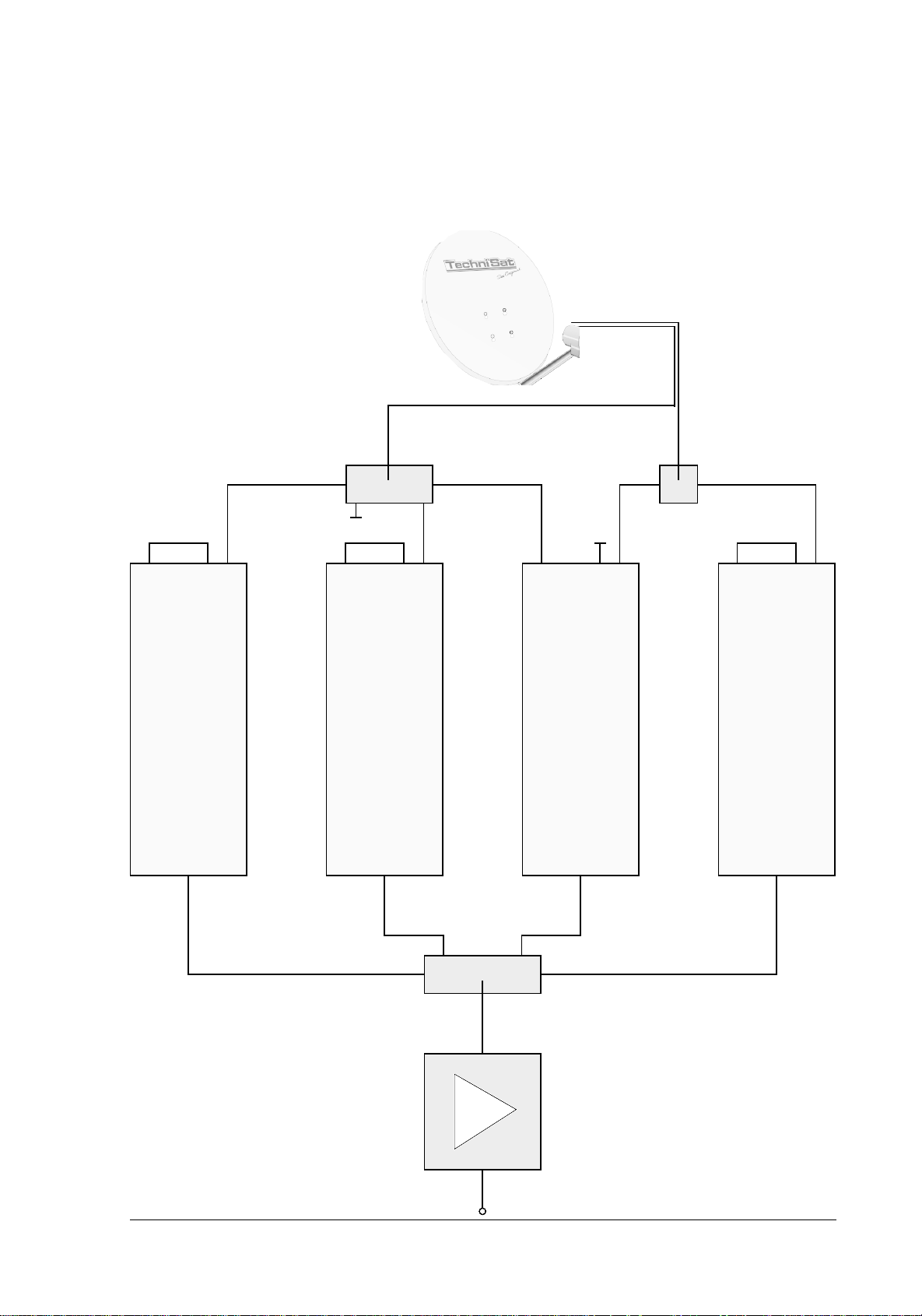
SATMAN 1000
+ UNYSAT DUAL OUTPUT LNB
6099/8680
9 x H 7 x V
0000/3103
0000/3102
E1 A E2
TechniNet
Out Out Out Out
E1 A E2
E1 A E2 E1 A E2
TechniNet TechniNet TechniNet
93 dBµV 93 dBµV 93 dBµV
0000/3065
85 dBµV
93 dBµV
The equipment is approved in terms of
CE standards, and complies with all relevant EU standards. Subject to change
and printing errors. Correct as at 12/98
Trunk line out
TechniTop 27
0000/5601
105 dBµV
Page 8

Multipurpose-Display
Operating keys
Memory key
SUB-D-Decoder socket
Input 1
Input 2
Level controls
for channels 1 - 4
Output
View from belowViev from above
UES/1206/98
 Loading...