


Table Of Contents
COVER
1Note
2Location of Controls
 3 To Supply Power Source 3.1 Power Supply to Main
Circuit
3.2 Operation Check
4 Operation Checks and
Component
ReplacementProcedures
5 Type Illustration of ICs,
Transistors and Diodes
 6 Schematic Diagram
6.1 Schematic Diagram
Notes
6.2 Schematic Diagram
7 Printed Circuit Board
Diagram
8 Block Diagram
9 Wiring Connection Diagram
 10 Measurements and Adjustments
10.1 Measurement instruments and Special tools
10.2 Output Voltage Adjustment
 11 Terminal Function of ICs
11.1 IC701 (M38503M2404F) : Micro Computer
12 Replacement Parts List
PV
13 Cabinet Parts Location
PV
14 Packaging
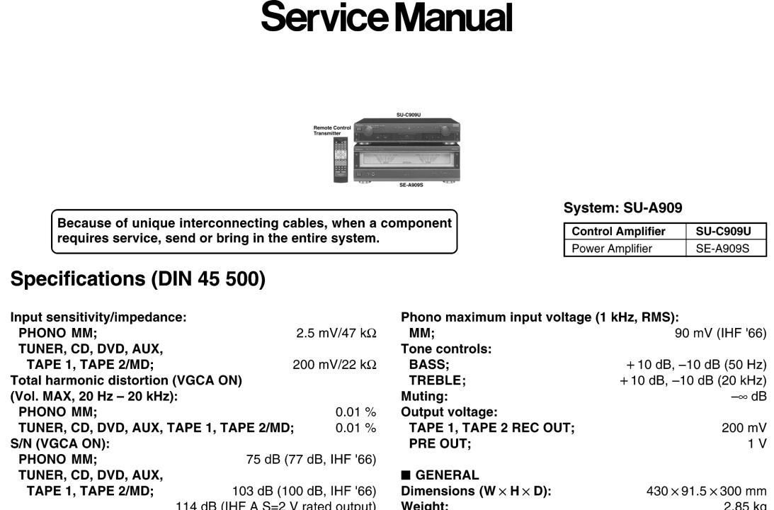
Service Manual
TOP NEXT
AD9907176C2
Control Amplifier
● SU-C909U
Colour
(K)..........Black Type
Area
(E)..........Europe and Russia.
© 1999 Matsushita Electric Industrial Co., Ltd. All rights reserved. Unauthorized copying and distribution is a violation of law.
•@
TOP NEXT
Table Of Contents
COVER
1Note
2Location of Controls
3To Supply Power Source
3.1 Power Supply to Main Circuit
3.2 Operation Check
4 Operation Checks and Component ReplacementProcedures
5 Type Illustration of ICs, Transistors and Diodes
6 Schematic Diagram
6.1 Schematic Diagram Notes
6.2 Schematic Diagram
7 Printed Circuit Board Diagram
8 Block Diagram
9 Wiring Connection Diagram
10 Measurements and Adjustments
10.1 Measurement instruments and Special tools
10.2 Output Voltage Adjustment
11 Terminal Function of ICs
11.1 IC701 (M38503M2404F) : Micro Computer

12 Replacement Parts List PV
13 Cabinet Parts Location PV
14 Packaging
Service Manual
TOP NEXT
AD9907176C2
Control Amplifier
● SU-C909U
Colour
(K)..........Black Type
Area
(E)..........Europe and Russia.
© 1999 Matsushita Electric Industrial Co., Ltd. All rights reserved. Unauthorized copying and distribution is a violation of law.
•@
TOP NEXT
1 Note
TOP PREVIOUS NEXT
Refer to the servise manual for Model No. SE-A909S (ORDER No. AD9907177C2) for information on Accessories, Connections, Operations and Packaging.
•@
TOP PREVIOUS NEXT

2 Location of Controls
TOP PREVIOUS NEXT
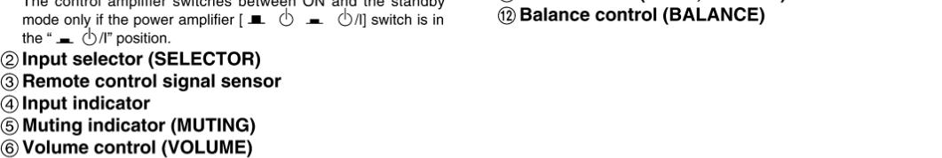
•@
TOP PREVIOUS NEXT
3 To Supply Power Source
TOP PREVIOUS NEXT
This unit SU-C909U is designed to operate on power supplied from the Power Amplifier SE-A909S.
When operating the unit SU-C909U alone for testing and servicing, without having power supplied from the Power Amplifier SE-A909S, use the following method.
3.1 Power Supply to Main Circuit
3.2 Operation Check
•@
TOP PREVIOUS NEXT
3.1 Power Supply to Main Circuit
TOP PREVIOUS NEXT
1.Apply 10 V AC power to the section between the point TP1 and the point TP2 . Shown in Fig.1
2.Connect the DC+12 V to+15 V (more than 0.1 A) to the point TP5 , and the GND terminal to the point TP4 using the DC power supply. Shown in Fig.1
3.Connect the DC -12 V to -15 V (more than 0.1 A) to the point TP3 , and the GND terminal to the point TP4 using the DC power supply. Shown in Fig.1
•@
TOP PREVIOUS NEXT

3.2 Operation Check
TOP PREVIOUS NEXT
1.Input a signal (1 kHz, 100 mV) to the each line-in terminal.
2.Connect the oscilloscope or the speaker with the built-in amplifier to the PRE OUT terminals and check if the signals are outputting from this unit.
Fig.1
•@
TOP PREVIOUS NEXT
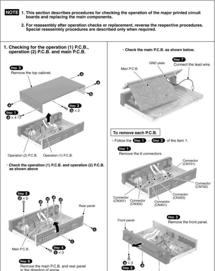
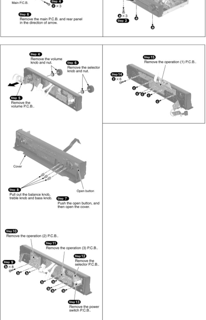
4 Operation Checks and Component
Replacement/Procedures
TOP PREVIOUS NEXT

•@
TOP PREVIOUS NEXT

5 Type Illustration of ICs, Transistors and
Diodes
TOP PREVIOUS NEXT
•@
TOP PREVIOUS NEXT
6 Schematic Diagram
TOP PREVIOUS NEXT
6.1 Schematic Diagram Notes
6.2 Schematic Diagram
•@
TOP PREVIOUS NEXT

6.1 Schematic Diagram Notes
TOP PREVIOUS NEXT
This schematic diagram may be modified at any time with the development of new technology.
Notes:
S801:
VGCA switch (  )
)
S802:
Tape monitor switch (TAPE MONITOR)
S804:
Input select switch (SELECTOR)
S805:
Unit on/off switch (
 /I)
/I)
VR301:
Volume control VR (VOLUME)
VR311:
Output voltage adjustment VR (L ch)
VR312:
Output voltage adjustment VR (R ch)
VR401:
Balance control VR (BALANCE)
VR402:
Tone control VR (BASS)
VR403:
Tone control VR (TREBLE)
Indicated voltage values are the standard values for the unit measured by the DC electronic circuit tester (high-impedance) with the chassis taken as standard. Therefore, there may exist some errors in the voltage values, depending on theinternal impedance of the DC circuit tester.
No mark : Power ON
Important safety notice:
Components identified by mark have special characteristics important for safety.
Furthermore, special parts which have purposes of fire-retardant (resistors), high-quality sound (capacitors), low-noise (resistors), etc. are used.
When replacing any of components, be sure to use only manufacturers specified parts shown in the parts list.
Caution!
IC and LSI are sensitive to static electricity.
Secondary trouble can be prevented by taking care during repair.
Cover the parts boxes made of plastics with aluminum foil.
 Loading...