


Table Of Contents
COVER
1 Before Repair
2 Protection Circuitry
3Accessories
4Caution for AC Mains Lead
5Operations
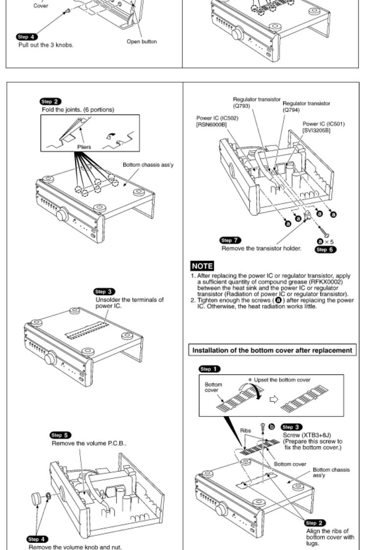
6Operation Checks and Component ReplacementProcedures
7About the+/- 15 V Line Abnormality Detect Function
7.1 About the abnormality detect function with the operation LED turned off
8 Schematic Diagram
8.1 Schematic Diagram Notes
8.2 Schematic Diagram
9 Printed Circuit Board Diagram
10 Wiring Connection Diagram
11 Type Illustration of ICs, Transistors and Diodes
12 Block Diagram
13 Measurements and Adjustments
13.1 Measuring Instruments and Special Tools
13.2 Output Voltage Adjustment

14 Terminal Function of ICs
14.1 IC801 (M38503M2405F) : System Control
15 Replacement Parts List PV
16 Cabinet Parts Location PV
17 Packaging
Service Manual
TOP NEXT
AD9908184C2
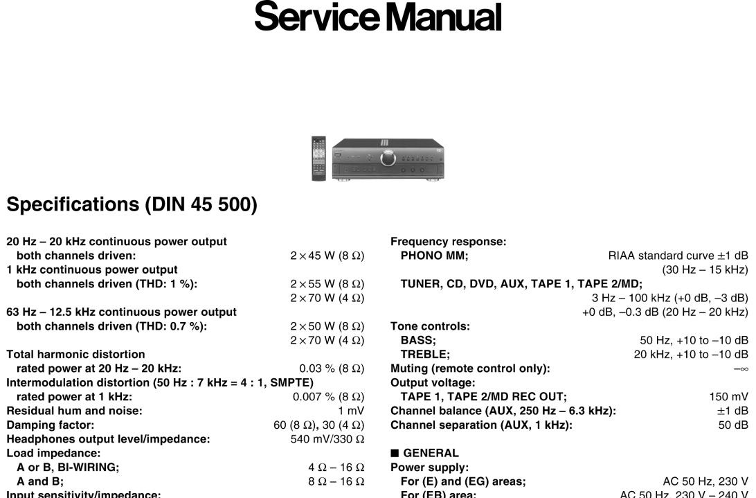
Stereo Integrated Amplifier
SU-A707 |
|
Colour |
|
(K)............... |
Black Type |
Areas |
|
(E)............... |
Europe and Russia. |
(EB)............ |
Great Britain. |
(EG)............ |
Germany, France and Italy. |
© 1999 Matsushita Electric Industrial Co., Ltd. All rights reserved. Unauthorized copying and distribution is a violation of law.
•@
TOP NEXT
1 Before Repair
TOP PREVIOUS NEXT
1.Turn off the power supply. Using a 10Ω, 10 W resistor, connect both ends of power supply capacitors (C701, C702) in order to discharge the voltage.
2.Before turning the power supply on, after completion of repair, slowly apply the primary voltage by using a power supply voltage controller to make sure that the consumed current at 50 Hz in NO SIGNAL mode should be shown below with respectto supply voltage 230/240 V.
Power supply |
AC 230 V, 50 |
AC 240 V, 50 |
voltage |
Hz |
Hz |
Consumed current |
70-270 mA |
60-260 mA |
•@
TOP PREVIOUS NEXT
2 Protection Circuitry
TOP PREVIOUS NEXT
The protection circuitry may have operated if either of the following conditions is noticed:
No sound is heard when the power is switched ON.
Sound stops during a performance.
The functions of this circuitry is to prevent circuitry damage if, for example, the positive and negative speaker connection wires are shorted, or if speaker systems with an impedance less than the indicated rated impedance of this unit are used.
If this occurs, follow the procedure outlined bellow:
1.Switch OFF the power.
2.Determine the cause of the problem and correct it.
3.Switch ON the power once again.
Note:
When the protection circuitry functions, the unit will not operate unless the power is first switched OFF and ON again.
•@
TOP PREVIOUS NEXT
3 Accessories
TOP PREVIOUS NEXT |
|
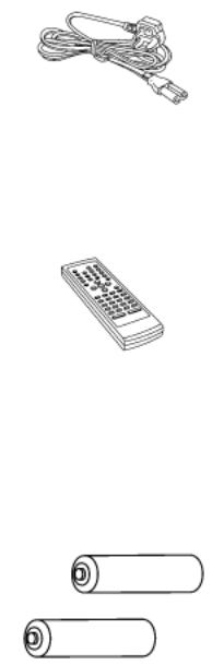
AC mains lead |
|
(E) and (EG) areas : (RJA0019-X)......... |
1 pc. |
(EB) area : (RJA0053-2X)........................ |
1 pc. |
Remote control transmitter |
|
(RAK-SUA11WH)............................................. |
1 pc. |
Batteries |
|
(R6/LR6, AA, UM-3)............................................. |
2 pcs. |
Note: These are available on sales route. |
|
•@
TOP PREVIOUS NEXT

4 Caution for AC Mains Lead
TOP PREVIOUS NEXT

5 Operations
TOP PREVIOUS NEXT
•@
TOP PREVIOUS NEXT
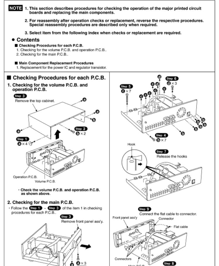
6 Operation Checks and Component
Replacement/Procedures
TOP PREVIOUS NEXT
•@
TOP PREVIOUS NEXT
7 About the+/- 15 V Line Abnormality Detect Function
TOP PREVIOUS NEXT
1.This model features the function that shuts down the main power source when it check the± 15 V line with the IC801 (microcomputer) and find the different voltage. (After power is turned on, the unit enters the stand-by mode.)
2.When the unit enters stand-by mode with abnormality detected, check the circuits around the± 15 V line. (Specially check the abnormality of the stabilizing power source circuit.)
3.To clear this stand-by mode, short-circuit the TP801 land on the circuit board. However, clearance of the stand-by mode and turn on the electricity when the repair is not completed may lead to another trouble. Therefore, be especially carefulto do so. (Do not turn on the electricity for a long time.)
4.When the repair is completed, leave the TP801 open.
7.1 About the abnormality detect function with the operation LED turned off
•@
TOP PREVIOUS NEXT
7.1 About the abnormality detect function with the operation LED turned off
TOP PREVIOUS NEXT
1.If the operation LED is turned off, there are possibilities of the following abnormalities in addition to the LED itself malfunctioning:
2.Power amplifier´s malfunction by the speaker terminal short-circuit.
3.Malfunction of cooling fan.
The unit features the function that detects above abnormalities.
•@
TOP PREVIOUS NEXT
8 Schematic Diagram
TOP PREVIOUS NEXT
8.1 Schematic Diagram Notes
8.2 Schematic Diagram
•@
TOP PREVIOUS NEXT
8.1 Schematic Diagram Notes
TOP PREVIOUS NEXT
This schematic diagram may be modified at any time with the development of new technology.
Notes:
S204:
Unit on/off switch (/I)
S801:
Input select switch (TAPE 1)
S802:
Input select switch (TAPE 2/MD)
S803:
Input select switch (AUX)
S804:
Input select switch (DVD)
S805:
Input select switch (CD)
S806:
Input select switch (TUNER)
S807:
Input select switch (PHONO)
S808:
VGCA switch ()
S809:
Tape monitor (SOURCE) switch (TAPE MONITOR)
S810:
Tape monitor (TAPE 2/MD) switch (TAPE MONITOR)
S811:
Tape monitor (TAPE 1) switch (TAPE MONITOR)
S812:
Speaker select switch (SPEAKER B)
S813:
Speaker select switch (SPEAKER A)
VR201:
Volume control VR (VOLUME)
VR202:
Balance control VR (BALANCE)
VR203:
Output voltage adjustment VR (L ch)
VR204:
Output voltage adjustment VR (R ch)
VR301:
Tone control VR (BASS)
VR302:
Tone control VR (TREBLE)
Indicated voltage values are the standard values for the unit measured by the DC electronic circuit tester (high-impedance) with the chassis taken as standard. Therefore, there may exist some errors in the voltage values, depending on theinternal impedance of the DC circuit tester.
No mark : Power ON
Important safety notice:
Components identified by mark have special characteristics important for safety.
Furthermore, special parts which have purposes of fire-retardant (resistors), high-quality sound (capacitors), low-noise (resistors), etc. are used.
When replacing any of components, be sure to use only manufacturers specified parts shown in the parts list.
Caution!
IC and LSI are sensitive to static electricity.
Secondary trouble can be prevented by taking care during repair.
Cover the parts boxes made of plastics with aluminum foil.
Ground the soldering iron.
Put a conductive mat on the work table.
Do not touch the legs of IC or LSI with the fingers directly.
Voltage and signal line
:Positive voltage line
:Negative voltage line
:Phono signal line
:Tape rec signal line
•@
 Loading...