


ORDER NO. MD9707082C2
AV Control Stereo Receiver
*Manufactured under license from Dolby Laboratories Licensing Corporation. Additionally licensed under one or more of the following patents: U.S. numbers 3,632,886,3,746,792 and 3,959,590; Canadian numbers 1,004,603 and 1,037,877.
"Dolby" and the double-D symbol are trade marks of Dolby Laboratories Licensing Corporation.
Receiver
SA-EX310
Colour
(K) . . . . . . . . Black Type
Area
Suffix for |
Area |
Colour |
|
Model No. |
|||
|
|
||
|
|
|
|
(E) |
Europe |
|
|
|
|
|
|
(EB) |
Great Britain |
(K) |
|
|
|
|
|
(EG) |
Germany and Italy |
|
|
|
|
|
SPECIFICATIONS\ТЕХНИЧЕСКИЕ ХАРАКТЕРИСТИКИ PROTECTION CIRCUITRY\ СИСТЕМА ЗАЩИТЫ
CAUTION FOR AC MAIN LEADS\ МЕРЫ БЕЗОПАСНОСТИ ПРИ РАБОТЕ СО ШНУРОМ ПИТАНИЯ ПЕРЕМЕННОГО ТОКА
OPERATION CHECKS AND MAIN COMPONENT REPLACEMENT PROCEDURES\ПРОВЕРКА РАБОТОСПОСОБНОСТИ И ЗАМЕНА ОСНОВНЫХ КОМПОНЕНТОВ
FAN MOTOR TROUBLESHOOTING\ НЕИСПРАВНОСТИ ДВИГАТЕЛЯ ОХЛАЖДЕНИЯ TROUBLESHOOTING\ НЕИСПРАВНОСТИ И МЕТОДЫ ИХ УСТРАНЕНИЯ
BLOCK DIAGRAM\ БЛОК-СХЕМА
TERMINAL FUNCTIONS OF IC's\ ФУНКЦИОНАЛЬНОЕ НАЗНАЧЕНИЕ ВЫВОДОВ ИНТЕГРАЛЬНЫХ МИКРОСХЕМ
TERMINAL GUIDE OF IC's, TRANSISTORS & DIODES\ ЦОКОЛЕВКА ВЫВОДОВ ИНТЕГРАЛЬНЫХ МИКРОСХЕМ, ТРАНЗИСТОРОВ И ДИОДОВ
SCHEMATIC DIAGRAMS\ ПРИНЦИПИАЛЬНЫЕ СХЕМЫ PRINTED CIRCUIT BOARDS\ ПЕЧАТНЫЕ ПЛАТЫ WIRING CONNECTION DIAGRAM\ СХЕМА СОЕДИНЕНИЯ
CABINET PARTS LOCATION\ РАСПОЛОЖЕНИЕ ЧАСТЕЙ КОРПУСА REPLACEMENT PARTS LIST\ СПИСОК ЗАПАСНЫХ ЧАСТЕЙ RESISTORS & CAPACITORS\ РЕЗИСТОРЫ И КОНДЕНСАТОРЫ PACKAGING\УПАКОВКА
© 1997 Matsushita Electronics (S) Pte. Ltd.
® All rights reserved. Unauthorized copying and distribution is a violation of law.
SA-EX310

 Specifications

 FM Tuner Section
Frequency range |
|
87.50 — 108.00 MHz |
||
Sensitivity |
|
|
1.5 µ V / 75Ω |
|
|
S/N 30 dB |
|
||
|
S/N 26 dB |
|
1.3 µ V / 75Ω |
|
|
S/N 20 dB |
|
1.2 µ V / 75Ω |
|
IHF |
usable |
sensitivity |
|
1.5 µ V / 75Ω (IHF '58) |
IHF |
46 dB |
stereo quieting |
sensitivity |
22 µ V / |
|
|
|
|
75Ω |
Total harmonic distortion |
|
|
||
|
MONO |
|
0.2% |
|
|
STEREO |
|
0.3% |
|
S/N |
|
|
|
|
|
MONO |
|
60 dB (75 dB, IHF) |
|
|
STEREO |
|
58 dB (71 dB, IHF) |
|
Frequency response |
20Hz — 15 kHz (+1dB, –2dB) |
|||
Alternate channel selectivity |
+ 400 kHz |
65 dB |
||
Capture ratio |
|
1 dB |
||
Image rejection at 98MHz |
|
40 dB |
||
IF rejection at 98MHz |
|
70 dB |
||
Spurious response rejection at 98MHz |
70 dB |
|||
AM suppression |
|
50 dB |
||
Stereo separation 1kHz |
|
40 dB |
||
Carrier leak |
|
|
|
|
|
19kHz |
|
-30 dB (-35 dB, IHF) |
|
IF rejection ( at 999 kHz ) |
|
55 dB |
||

 Amplifier Section
Power output |
(at 240 V) |
2 X 60 W(4Ω ) |
|||
DIN 1 kHz (T.H.D. 1%) |
|||||
|
40 Hz–20 kHz continuous power output |
2 X 40 W(8Ω ) |
|||
|
both channels driven |
||||
Total |
harmonic |
distortion |
0.8 % (8Ω ) |
||
Rated power at 40 Hz – 20kHz |
|||||
Half power at 1 kHz |
0.07 % (8Ω ) |
||||
Power output at the Dolby Pro Logic operation |
|
||||
DIN 1 kHz |
( T.H.D. 1 % ) |
2 X 50 W (4Ω ) |
|||
|
Front |
|
|
||
|
Center |
|
|
50 W (8Ω |
) |
|
Surround |
50 W (8Ω |
) |
||
Damping factor |
|
30 (8Ω |
) |
||
Load |
impedance |
4 - 16 Ω |
|
||
|
Front |
|
|
|
|
|
Center |
|
|
8 - 16 Ω |
|
|
Surround |
4 - 16 Ω |
|
||
Power bandwidth both channels driven, -3 dB 10 Hz - 40 kHz (8Ω) |
|
||||
Intermodulation |
distortion rated |
0.5 % (8Ω |
|
||
power at 60 Hz : 7 kHz = 4:1, SMPTE |
) |
||||
Frequency response |
|
|
|||
PHONO |
|
RIAA standard curve(30Hz-15kHz) +0.8 dB |
|||
CD, TAPE, VCR, TV/DVD |
10Hz – 40kHz, +3 dB |
||||
Input sensitivity and impedance |
3 mV / 47 kΩ |
|
|||
PHONO |
|
|
|
||
CD, TAPE, VCR, TV/DVD |
200 mV / 22 kΩ |
|
|||
S/N at rated power ( 8Ω ) |
|
|
|||
PHONO |
|
|
70 dB (IHF, A: 80 dB) |
||
CD, TAPE, VCR, TV/DVD |
75 dB (IHF, A: 85 dB) |
||||
38kHz |
-50 dB (-55 dB, IHF) |
|
Channel balance (250 Hz - 6.3 kHz ) |
+1.5 dB |
|
Limitting point |
1.2 µ V |
|
Bandwidth |
|
|
IF amplifier |
180 |
kHz |
FM demodulator |
1000 |
kHz |
Antenna terminal(s) |
75Ω (unbalanced) |
|

 Video Section
Output voltage at 1V input (unbalanced) |
1±0.1 Vp-p |
Maximum input voltage |
1.5 Vp-p |
Input/output impedance |
75 Ω ( unbalanced) |

 AM Tuner Section
Frequency range |
AM |
|
|
( 9 kHz steps ) |
522 — 1611 kHz |
|
( 10 kHz steps ) |
530 — 1620 kHz |
Sensitivty |
|
20 µ V, 330 µ V / m |
Selectivity ( at 999 kHz ) |
55 dB |
|
Image rejection |
( at 999 kHz ) |
40 dB |
Tone controls |
|
BASS |
50 Hz , +10 to -10 dB |
TREBLE |
20 kHz, +10 to -10 dB |
Output voltage |
|
TAPE REC (OUT), VCR OUT |
200 mV |
Channel balance (250 Hz - 6.3 kHz) |
+ 1 dB |
Channel separation |
55 dB |
Headphones output level and impedance |
430 mV / 330 Ω |
Subwoofer frequency responce |
7 –100 Hz, + 3 dB |

 General
Power consumption |
|
160 W |
Power supply |
|
|
E , EG |
AC 230 |
V, 50 Hz |
EB |
AC 230 - 240 |
V, 50 Hz |
Dimensions (W x H x D) |
430 x 136 x 309 mm |
|
Weight |
|
7.3 kg |
Notes :
1.Specifications are subject to change without notice. Weight and dimensions are approximate.
2.Total harmonic distortion is measured by the digital spectrum

 Protection Circuitry
The protection circuitry may have operated if either of the following conditions are noticed:
•No sound is heard when the power is turned on.
•Sound stops during a performance.
The function of this circuitry is to prevent circuitry damage if, for example, the positive and negative speaker connection wires are "shorted", or if speaker systems with an impedance less than
the indicated rated impedance of the amplifier are used. If this occurs, follow the procedure outlines below:
1.Turn off the power.
2.Determine the cause of the problem and correct it.
3.Turn on the power once again after one minute.
Note:
When the protection circuitry functions, the unit will not operate unless the power is first turned off and then on again.

SA-EX310

 Caution for AC Main Leads
(For “EB” area code model only.)
For your safety, please read the following text carefully.
This appliance is supplied with a moulded three pin mains plug for your safety and convenience.
A 5-ampere fuse is fitted in this plug.
Should the fuse need to be replaced please ensure that the replacement fuse has a rating of 5-ampere and that it is approved by ASTA or BSI to BS1362.
Check for the ASTA mark ASA or the BSI mark  on the body of the fuse.
If the plug contains a removable fuse cover you must ensure that it is refitted when the fuse is replaced.
If you lose the fuse cover, the plug must not be used until a replacement cover is obtained.
A replacement fuse cover can be purchased from your local dealer.
CAUTION !
IF THE FITTED MOULDED PLUG IS UNSUITABLE FOR THE SOCKET OUTLET IN YOUR HOME THEN THE FUSE SHOULD BE REMOVED AND THE PLUG CUT OFF AND DISPOSED OFF SAFELY.
THERE IS A DANGER OF SEVERE ELECTRICAL SHOCK IF THE CUT OFF PLUG IS INSERTED INTO ANY 13-AMPERE SOCKET.
If a new plug is to be fitted, please observe the wiring code as shown below.
If in any doubt please consult a qualified electrician.
THIS PLUG IS NOT WATERPROOF—KEEP DRY.
Before use
Remove the connector cover.
How to replace the fuse
The location of the fuse differ according to the type of AC mains plug (figures A and B). Confirm the AC mains plug fitted and follow the instructions below.
Illustrations may differ from actual AC mains plug.
1. Open the fuse cover with a screwdriver. Figure A
Fuse cover
Figure B
IMPORTANT
The wires in this mains lead are coloured in accordance with the following code:
Blue: Neutral Brown: Live
As these colours may not correspond with the coloured markings identifying the terminals in your plug, proceed as follows:
The wire which is coloured Blue must be connected to the terminal which is marked with the letter N or coloured Black or Blue.
The wire which is coloured Brown must be connected to the terminal which is marked with the letter L or coloured Brown or Red.
WARNING: DO NOT CONNECT EITHER WIRE TO THE EARTH TERMINAL WHICH IS MARKED WITH THE LETTER E, BY THE EARTH SYMBOL OR COLOURED GREEN OR GREEN/YELLOW.
2.Replace the fuse and close or attach the fuse cover.
Figure A
Fuse
 (5 ampere)
Figure B |
Fuse |
|
(5 ampere) |
SA-EX310

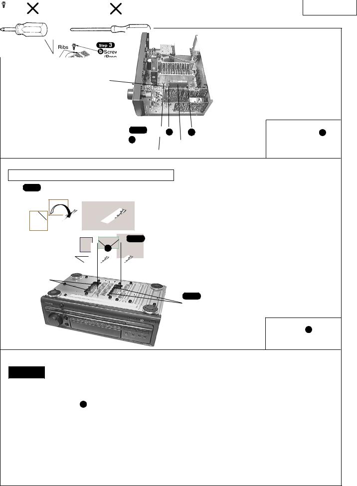
 Operation Checks and Main Component Replacement Procedures
"ATTENTIONSERVICER" Some chassis components may have sharp edges. Be careful when disassembling and servicing. Please take note that the diagrams shown are for model SA-EX510 which is similar to SAEX310.
1.This section describes procedures for checking the operation of the major printed circuit boards and replacing the main components.
2.For reassembly after operation checks or replacement, reverse the respective procedures.
Special reassembly procedures are described only when required.
3. Select items from the following index when checks or replacement are required.
• Contents
|
• Checking Procedure For Each Major P.C.B ........................................................................................ |
4 ~ 6 |
|||
|
•MainComponentReplacementProcedures........................................................................................ |
6~8 |
|||
Checking Procedure For Each Major P.C.B. |
|
||||
1. Checking of the Panel P.C.B., andTuner P.C.B. |
|
|
|||
|
|
|
|
a |
|
|
|
|
|
a |
|
|
Step 1 |
|
b |
|
|
|
a |
X |
Step 2 |
|
|
|
|
|
|
||
|
|
4 |
b |
X |
|
|
|
a |
|
2 |
|
|
|
|
|
|
|
|
PANEL P.C.B. |
|
|
|
|
|
(SolderSide) |
|
|
|
|
IN/OUT TERMINAL P.C.B. |
|
|
a |
||
(SolderSide) |
|
|
|
[SNE2129-1] (Black) |
|
|
|
|
|
||
|
TUNER P.C.B. |
|
|
b |
|
|
(SolderSide) |
|
[XTBS3+8JFZ1] (Black) |
||
|
|
|
|
||
2. Checking of the In/Out Terminal P.C.B. |
|
|
|||
Step 1 |
|
|
|
|
|
Remove the top cabinet. |
2 |
|
|
||
Step 3 |
|
|
|
|
|
Release the catch, pull |
|
Catch |
|||
the rear panel in the |
|
|
|||
|
|
|
|
||
direction of arrow 1 |
and |
|
Step 2 |
||
simultaniously |
remove the |
|
|||
|
|
|
|||
In/Out Terminal |
P.C.B. |
in |
|
b |
X 14 |
the direction of arrow |
2 |
|
|
|
|
. |
IN/OUTTERMINAL |
|
|
||
P.C.B. |
|
|
|
||
|
|
|
|
||
|
|
|
Catch |
|
|
SA-EX310
To Remove Front Panel, Panel P.C.B., Power Switch |
Step 4 |
|
P.C.B. and Headphone Jack P.C.B. |
||
Remove the Volume Knob |
||
|
||
|
Step 1
Remove the top cabinet.
bX 3
Step 2 |
b |
Step 3
Remove the front panel in the direction of arrow.
and Nut. |
Step 6 |
|
c |
c X |
c |
c |
18 |
|
c |
|
|
|
||
|
|
|
Step 5
Pull out 3 knobs.
|
c |
c |
c |
c |
c |
d |
X 1 |
|
|
|
|
|
|||
|
|
|
|
|
|
|
|
b |
|
|
|
|
Step 7 |
||
|
|
|
|
|
|
|
|
|
Panel P.C.B. |
|
|
|
|
|
|
Power Switch P.C.B. |
|
|
|
|
|
|
|
|
|
|
|
|
c |
|
|
|
|
|
[XTBS26+10J] |
|
|
||
|
Step 8 |
|
|
|
d |
|
|
Headphone Jack P.C.B. |
Pull out the Headphone |
|
|
|
|
|
|
Jack P.C.B. |
|
|
[RHD26016] |
|
|
||
|
|
|
|
|
|||
|
|
|
|
|
|
||
3. Checking of the MAIN P.C.B.
Step 1 |
|
|
|
Remove the top cabinet. |
|
|
|
Step 2 |
|
|
|
Remove the front panel. |
|
b |
|
|
|
||
|
|
b |
|
Step 3 |
|
b |
|
|
|
||
f X |
f |
b |
|
13 |
|||
|
|
||
|
Step 5 b |
X 4 |
|
|
Step 7 |
|
|
f |
Lift the rear panel in the direction of arrow |
||
2 . |
|
||
|
|
||
|
2 |
|
|
 catch
catch
|
Step 4 |
|
||
f |
e |
X 4 |
|
|
|
|
|
||
|
|
|
1 |
|
Step 6 |
|
|
|
|
Release 2 catches and pull the rear panel in |
catch |
|||
the direction of arrow |
1 for about 10mm. |
|||
|
||||
(Note : Main, Tuner and In/Out Terminal P.C.B. are attach to the rear panel)
SA-EX310
Step 8
Connect the front panel to the main P.C.B. as shown.
• Check the Main P.C.B. as shown
•
MAIN P.C.B. (Solder Side)
e
[XTB3+8FFZ] (Black)
f
[XTB3+20JFZ] (Black)

 Main Component Replacement Procedures
1. Replacement of the Power IC and
Regulator Transistor
Step 1 |
Step 3 Fold the joints. (6 joints) |
|
|
Remove the top cabinet. |
|
Step 2 Cut the joints as shown below. (6 joints)
Step 4
Desolder the terminals of Power IC and
Regulator Transistor.
SA-EX310
Regulator transistor (Q701,Q708) [2SD2374PQAU,2SB1548PQAU]
Step 5 |
g |
g |
g |
|
|||
g X 3 |
|
Power IC (IC602) |
|
|
|
[XTW3+15T] |
|
|
|
[RSN3305-P] |
|
|
|
|
Installation of the bottom cover after replacement
Step 1
*
h |
Ribs
Lugs
Step 3
Screw (XTB3+8J)
(Prepare this screw to fix the bottom cover.)
Step 2
Align the ribs of bottom cover into the lugs.
h
[XTB3+8J] (Black)
CAUTION
1. After replacing the power IC or regulator transistor, apply a sufficient quantity of compound grease (RFKX0002/SZZ0L15) between the
heat |
sink and the power IC or regulator transistor (Radiation |
of power IC). |
g |
2.Tighten enough the screws ( ) after replacing the power IC and regulator transistor. Otherwise, the heat radiation works little.
3.When installing or removing the power IC or transistor holder, be sure to use an offset screwdriver.
•A long straight screwdriver cannot be used for removing or mounting the screws since its long grip interferes with the neighbouring P.C.B. and transformer.(See Fig.1 & 3)
•A short straight screwdriver may be used for removal, but cannot be used for mounting because the limited space in the unit will not allow sufficient tightening torque.(See Fig.2 & 3)
A short straight screwdriver |
A long straight screwdriver |
Fig.2 |
Fig.1 |
•Insufficient tightening will cause poor heat dissipation from the power IC and regulator transistor and,in the worst case, may lead to their thermal breakdown.
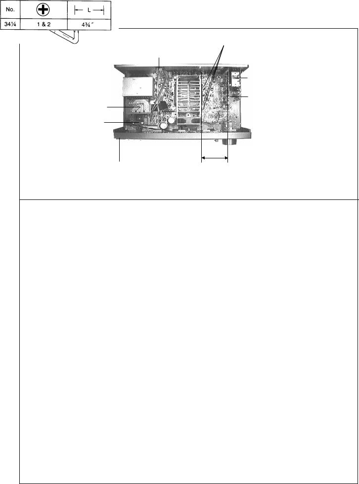
SA-EX310
Screws
AC In / Out
P.C.B.
Tuner & Tuner
Pack P.C.B.
Pro Logic
Transformer P.C.B.
P.C.B.
Power
P.C.B.
Fig.3
Front Panel |
About 9 cm |
|
|
|
(A long straight screwdriver |
|
connot be used) |
–––OFFSET SCREWDRIVER–––
•The PROTO offset screwdriver No.34-1/4 is recommended for use in the application above.
•The address of PROTO International Sales is as follows.
|
|
|
|
|
|
Phone: |
305-591-3828 |
|
|
|
|
Japan |
|
Europe |
|
|
|
|
|
|
Stanley-Proto Europe |
||
|
|
|
|
Stanley Works Japan |
Woodside, Sheffield |
||
|
|
|
|
2-7-16 Hyakunin-Cho |
539PD |
|
|
International Sales |
|
|
Shinjuku-ku |
|
England |
|
|
|
|
|
|
Tokyo 160 Japan |
Fax: 44-742-739-038 |
||
|
|
|
|
Fax: 81-3-3360-8456 |
Phone: |
44-742-768-888 |
|
International Sales Office |
Singapore, |
Indonesia, |
Phone: |
81-3-3360- |
|
|
|
Stanley-Proto Industrial Tools |
Philippines, Korea, Hong |
8458 |
|
Canada |
|
||
14117 Industrial Park Blvd. |
Kong, Malaysia, China. |
Mexico |
|
Stanley-Proto Canada |
|||
Covington, GA 30209 U.S.A. |
Stanley-Proto Asia Pacific |
|
1100 Corporate Drive |
||||
Fax: 706-786-4387 |
12 Gul Drive |
Herramientas Stanley S.A. |
Burlington, Ontorio |
||||
Phone: |
706-787-3800 |
Singapore 2262 |
DE C.V. |
|
Canada, L7L 5R6 |
||
|
|
Fax: 65-861-3206 |
Apartado Postal 675 |
Fax: 416-335-0075 |
|||
Australia, New Zealand & |
Phone: |
65-862-0883 |
72030 Puebla, Pue, Maxico |
Phone: |
416-335-0075 |
||
South Pacific |
|
|
|
Fax: 52-22-494-4880 |
|
|
|
Stanley-Proto Industrial Tools |
Thailand |
|
Phone: |
52-22-495-300 |
Middel East, Mediterranean |
||
P.O.Box 10 |
|
Stanley-Proto Thailand Ltd. |
South & Central America, |
& Africa |
|
||
400 Whitehorse Road |
1017 Moo 13 Bangkaew |
Stanley-MEMA |
|||||
Nunrweding 3131 |
Amphur Bangplee |
Puerto Rico, The Caribbian |
Cory House The Rlng |
||||
Victoria, Australia |
Samutprakarn, Thailand |
Stanley Inter-America |
Bracknell Berkshire |
||||
Fax: 61-3-894-1173 |
Fax: 66-2-316-6071 |
2101 N.W. 84th Ave. |
RG 12 1A2 |
|
|||
Phone: |
61-3-878-9244 |
Phone: |
66-2-316- |
Miami, Florida 33122 |
England |
|
|
|
|
8655 |
|
Fax: 305-594-4261 |
Fax: 44-344-485-526 |
||
|
|
|
|
|
|
Phone: |
44-344-51813 |
SA-EX310

 Fan Motor Troubleshooting
The Model SA-EX310 employ fan motor error sensing electronics.
If the cooling fan is not operating and "OVER LOAD" is displayed on the FL display, check the fan motor and its driving circuit.
"OVER LOAD" is displayed on the FL display.
Is the air |
|
|
|
|
cooling path blocked |
YES |
|
||
|
||||
or the fan motorjammed |
|
|
Remove the obstacle. |
|
|
|
|||
by any external |
|
|
||
|
|
|
||
obstacle ? |
|
|
|
|
|
|
|
||
|
NO |
|
|
|
|
|
|
|
|
|
|
|
|
|
|
|
|
|
|
Remove the fan from the unit. |
|
|
|
|
|
|
|
|
|
|
|
|
|
|
Is the fan |
NO |
Fan motor failure |
||||
motor's DC resistance |
||||||
|
|
|
Short circuit : DC resistance below 5Ω |
|||
|
|
|
||||
20 ~ 30Ω ? |
|
|
|
|||
|
|
|
Open circuit : DC resistance over 1kΩ |
|||
|
|
|
|
|
||
|
YES |
|
|
|
|
|
|
|
|
|
|
||
|
|
|
|
|
||
|
|
|
|
|
|
|
|
|
|
|
|
|
|
Reinstall the fan on the unit. |
|
|
|
|
||
|
|
|
|
|
|
|
|
|
|
|
|
|
|
|
|
|
|
|
Are the |
|
|
|
|
|
terminal voltage of |
||
|
|
|
|
Q772 and Q773 normal in both |
||
|
|
|
|
and inactive states of the |
||
|
|
|
|
fan motor ? |
||
|
|
|
|
(see table1.) |
||
|
(Voltage table) |
|
|
YES |
||
|
|
|
||||
|
|
|
|
|||
|
|
|
|
|
|
|
|
|
fan. off |
|
fan. on |
|
|
|
E |
–14.5V |
|
–14.5V |
|
|
Q772 |
C |
0V |
|
–14.5V |
|
|
|
|
|
|
|
|
|
|
B |
–14.5V |
|
0V |
|
|
|
E |
0V |
|
–8.5V |
|
|
|
|
|
|
|
|
|
Q773 |
C |
–14.5V |
|
–14.5V |
|
|
|
|
|
|
|
|
|
|
B |
0V |
|
–8.5V |
|
|
|
|
(Table 1) |
|
|
|
|
|
|
|
|
Is an audio signal |
||
|
|
|
|
present at pins 7 and 10 |
||
|
|
|
|
|
of IC601 |
|
NO |
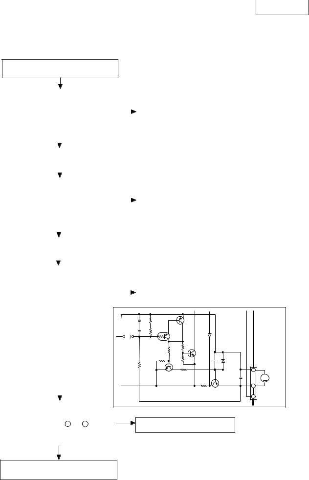
Check the integrity of Q772, Q773 and the fan |
|
|
|
|
|
|
motor driving circuit. (see Fig.1) |
|
|
|
|
|
C772 |
35V4.7 |
|
|
|
|||
|
|
|
C771 |
50V4.7 |
|
|
|
|
|
D771 D772 |
||||
1SS133 |
|
|||
|
|
|
R774 |
3.3M |
+ |
R772 |
+ |
R771 |
47K 47K
|
|
Q777 |
D774 |
1SS133 |
|
Q778 |
|||
|
|
|
||
R778 4.7K |
R777 |
47K |
Q776 |
|
R779 |
R773 |
10K |
|
C773 |
|
|
|
|
|
10K |
|
|
|
|
Q772 |
R775 |
|
|
|
330 |
|
|
||
|
|
|
|
|
|
|
|
R776 |
|
|
|
|
4.7 1/4W |
|
Q772,Q776
2SC1740SSTA
MOTOR DRIVE
Q777
2SA933SSTA
MOTOR DRIVE
Q778
RVTDTA114TST
MOTOR DRIVE
0.022 |
D773 MTZJ9R1CTA |
C775 |
0.022 |
Q773
2SB621AQSTA
REGULATOR
Fig.1
NO
The power IC ( IC601 ) is defective.
CP771
FAN
M MOTOR
YES
The fan motor, power ICs and fan driver are functioning normally.
SA-EX310

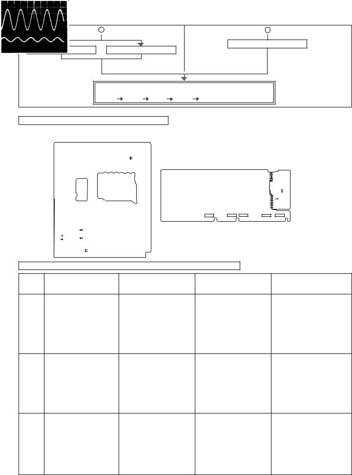
 Troubleshooting
This unit has test points on each circuit board block for use in troubleshooting.
CONNECTION
Connect either a CD player, tape deck or AF oscillator to the input terminals of the unit.
REQUIRED ITEMS
1. |
Testing with a CD player |
––––––– |
Test disc (SZZP1054C / first progarm, 1kHz, 0dB) |
|
2. |
Testing with a tape deck |
––––––– |
Test tape (QZZCLA / 315Hz, 0dB) |
|
3. Testing with a AF oscillator |
|
––––––– |
Set the output at 500Hz, 200mV |
|
4. |
Oscilloscope (min. 10MHz) |
----------- |
To measure the output waveform at the test points. |
|
TEST PROCEDURE FOR AMPLIFIER CIRCUIT
|
When the CD player AF oscillator is connected: |
When the tape deck is connected: |
||
Power on the unit. |
|
|
Power on the unit. |
|
Set the input selector button of the unit to the "CD" postion. |
Set the input selector button of the unit to the "TAPE MONITOR" |
|||
Set the Speaker select buttons of the unit to the SPEAKERS " |
postion. |
|||
ON" position. |
|
|
Set the Speaker ON/OFF button of the unit to the SPEAKERS |
|
|
|
|
|
"ON" position. |
|
Run the CD player |
or |
Run the AF oscillator |
|
|
|
|
|
Run the tape deck |
SZZP1054C / first program |
Oscillator output |
|
||
( |
1kHz, 0dB |
) |
(at 500Hz, 200mV) |
(315Hz,QZZCLA0dB) |
Using the Oscilloscope, check the output waveforms at the test points on the circuit boards of the unit in the following order: (L1,R1) 
 (L2,R2)
 (L3,R3)

 (L5,R5)

 (L6,R6).
Refer to page 10.
Note: Connect the '+' probe of the oscilloscope to each test point and the '–' probe to chassis ground.
TEST POINTS POSITIONS OF AMPLIFIER CIRCUIT
MAIN P.C.B. ( component side )
L6 |
J248 |
PANEL P.C.B. ( component side ) |
R6 |
J247 |
|
|
|
L3 R3

 VR502
VR502
J318 |
L5 |
|
C1001 |
J319 R5 |
L1 + |
||
|
|
R1 |
+ |
|
|
|
|
|
|
C1067 |
C1002 |
|
L2 |
|
|
|
|
|
|
|
R2 |
+C1004 |
|
SA-EX310
NORMAL WAVEFORMS OF AMPLIFIER CIRCUIT AND LIKELY FAULTY BLOCKS
Likely faulty block if the normal TP CD player Tape deck AF oscillator waveform shown at the left is not
present.
L1/R1 |
|
|
Input selector block IC402 & |
|
area |
|
|
|
|
0.5msec 2V |
1msec 500mV |
1msec 500mV |
||
L2/R2 |
|
|
Dolby pro logic blockIC1001 and |
|
|
|
|
IC1002& area |
|
0.5msec 2V |
1msec 500mV |
1msec 500mV |
||
L3/R3 |
|
|
Master volume block VR501 & |
|
|
|
|
area |
|
0.5msec 500mV |
1msec 50mV |
1msec 100mV |
||
L5/R5 |
|
|
Power limiter block Q601 to |
|
Q602 |
|
|
|
& area |
|
|
|
||
0.5msec 100mV* |
1msec 500mV |
1msec 500mV |
||
L6/R6 |
|
|
Main amplifier block IC601 & |
|
|
|
|
|
area |
0.5msec 5V* |
1msec 10V |
1msec 10V |
||
Measurement conditions. |
|
|
• |
|
|
|
Volume control (VR501), Treble |
||
control (VR512) and Bass control (VR511) positions |
|
|
: • |
|
*Volume control position (VR501) for these test |
|
: |
|
|
|
|
|||
CHECKINGPROCEDUREFORSURROUNDCIRCUIT
Outputting surround signal normally requires that opposite phase signals be applied to both the left and right channels. However, this unit incorporates a service mode, allowing the surround circuit to be tested using in-phase signals.
When the CD player or AF oscillator is connected : |
When the tape deck is connected : |
Power on the unit. |
Power on the unit. |
Set the input selector button of the unit to the "CD" |
Set the input selector button of the unit to the "TAPE |
position. |
MONITOR" position. |
While pressing both "+" and "-" of the surround |
While pressing both "+" and "-" of the surround |
level adjustment button "SURROUND, press the |
level adjustment button "SURROUND, press the |
"Power" button. |
"Power" button. |
The letter SURROUND flash on the FL display. |
The letter SURROUND flash on the FL display. |
A |
B |
SA-EX310
A |
|
|
|
B |
|
|
|
|
|
Run the tape deck |
|
Run the CD player |
Run the AF oscillator |
|
|
(315Hz,QZZCLA0dB) |
|
(SZZP1054C/first program) |
(Oscillator output ) |
|
|
||
|
|
|
|||
1kHz, 0dB |
at 500Hz, 200mV |
|
|
|
|
|
|
|
|
|
Note: Connect the '+' probe of |
Using the Oscilloscope, check the output waveforms at the test points on |
the oscilloscope to each |
||||
the circuit boards in the following order : |
|
test point and the '–' |
|||
(C1,S1) |
(C2,S2) |
(C3,S3) |
(C4,S4) |
(C5,S5). |
probe to chassis ground. |
• To exit the service mode, power off the unit.
TEST POINTS POSITIONS OF SOURROUND CIRCUIT
MAIN P.C.B. ( component side )
|
|
|
C5 |
J246 |
PANEL P.C.B. ( component side ) |
|
|
|
|
S5 |
J245 |
|
|
|
|
|
|
|
|
S2 |
|
|
|
|
|
|
C551 + |
|
|
|
|
|
|
C2 |
|
|
|
|
|
|
R552 |
|
|
C604 |
|
|
|
|
J316 |
|
+ S4 |
|
|
|
|
C3 |
C603 |
|
|
|
|
|
|
|
|
|
|
||
J313 |
S3 |
+ C4 |
|
|
|
|
|
|
S1 J22 |
|
|
|
|
|
|
C1 |
J21 |
|
|
|
NORMAL WAVEFORMS OF AMPLIFIER CIRCUIT AND LIKELY FAULTY BLOCKS |
|
|||||
|
|
|
|
|
|
Likely faulty block if the normal |
TP |
|
CD player |
Tape deck |
AF oscillator |
waveform shown at the left is not |
|
|
|
|
|
|
|
present. |
C1 |
|
|
|
|
|
Dolby pro logic block |
|
|
|
|
|
|
IC1001 and IC1002 & area |
S1 |
|
|
|
|
|
|
|
|
0.5msec 1V |
1msec 100mV |
1msec 200mV |
|
|
C2 |
|
|
|
|
|
Master volume block VR501 & |
|
|
|
|
|
|
area |
S2 |
|
|
|
|
|
|
|
0.5msec 200mV |
1msec 20mV |
1msec 50mV |
|
||
C3 |
|
|
|
|
|
Tone control block IC551 & area |
S3 |
|
|
|
|
|
|
|
0.5msec 200mV* |
1msec 500mV |
1msec 1V |
|
||
|
|
|
|
|
|
|
|
SA-EX310 |
|
|
|
|
|
|
|
|
|
|
|
|
|
|
|
|
|
|
|
|
|
NORMAL WAVEFORMS OF AMPLIFIER CIRCUIT AND LIKELY FAULTY BLOCKS |
|
|
|
|
|
||||
|
|
|
|
|
|
|
|
|
|
|
|
|
|
|
|
|
|
|
|
|
|
|
|
|
|
|
Likely faulty block if the normal |
|
|
TP |
CD player |
|
Tape deck |
AF oscillator |
|
waveform shown at the left is not |
|
||
|
|
|
|
|
|
|
present. |
|
|
|
|
|
|
|
|
|
|
|
|
C4 |
|
|
|
|
|
|
Power limiter block |
|
|
|
|
|
|
|
|
|
Q551 to Q552 & area |
|
|
S4 |
|
|
|
|
|
|
|
|
|
|
0.5msec 200mV* |
|
1msec 500mV |
1msec 1V |
|
|
|
|
|
C5 |
|
|
|
|
|
|
Main amplifier block IC601 & |
|
|
area |
|
|
|
|
|
|
IC602 & area |
|
|
S5 |
|
|
|
|
|
|
|
|
|
|
0.5msec 5V* |
|
1msec 10V |
1msec 1V* |
|
|
|
|
|
|
|
|
|
|
|
|
|
|
|
Measurement conditions. |
|
|
|
|
• |
||||
|
|
Volume control (VR501), Tremble |
|||||||
control (VR512) and Bass control (VR511) positions |
|
: |
|
• |
|||||
|
*Volume control position (VR501) for these test |
|
|
: |
|
|
|||
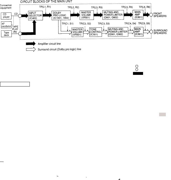
CIRCUIT BLOCKS

 OVERLOAD DETECTION FUNCTION
The HIC protection circuit functions if any cord at a speaker terminal is short-circuited or if the unit overheats because of improper operation. At the same time, OVERLOAD
 scrolls across the FL display.
In this state, all keys remain in operative; if any key is pressed,  SWITCH OFF POWER scrolls across the FL display.
If an overload occurs, immediately power off the unit and check the speaker connection, venting holes and cooling fans. After fixing any faults, power on the unit again and check for proper operation.
If no defects are found, or if the unit remains overload after it is power on again, check the circuit for faults.

SA-EX310

 Block Diagram
 Loading...