


Table Of Contents
COVER
1 Before Repairs
2 Protection Circuitry
3Accessories
4Caution for AC Main Leads
5Location of Controls
 6 Operation Checks and Component ReplacementProcedures
6.1 Checking for the AC IN P.C.B.
6.2 Checking for the operation P.C.B.
6.3 Checking for the main P. C.B.
6.4 Replacement for the regulator transistor
6.5 Replacement for the power IC
7 To Supply Power Source  8 Self-Diagnostic Mode
8.1 To display the malfunction code
8.2 To return to the normal display
 8.3 Display contents
8.3.1 U70 CD, U70 DECK (displayed automatically)
8.3.2 F61
9 Schematic Diagram Notes
10 Schematic Diagram
11 Printed Circuit Board Diagram
12 Type Illustration of ICs, Transistors and Diodes
13 Wiring Connection Diagram
 14 Terminal Function of ICs 14.1 IC901
(LC8A524A5N28):System Control/FL Drive
15 Block Diagram
16 Replacement Parts List
17 Cabinet Parts Location
18 Packaging
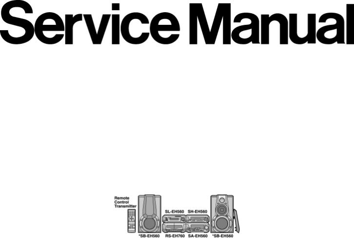
Service Manual
TOP NEXT
AD0002043C2
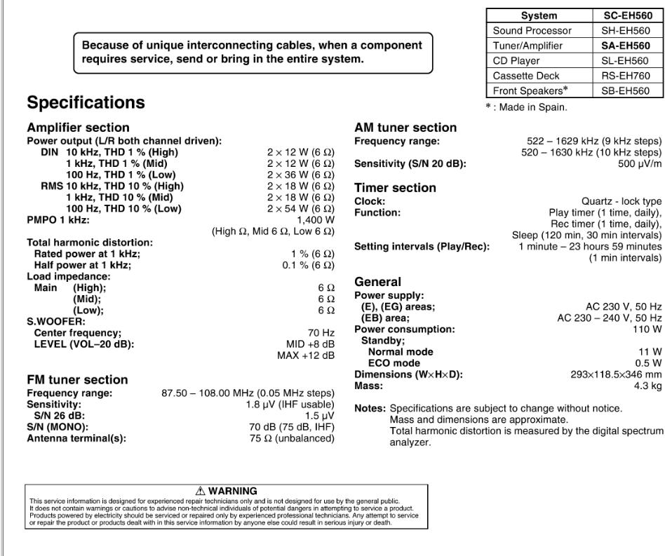
Tuner/Amplifier
SA-EH560 |
|
Colour |
|
(S)..................... |
Silver Type |
Areas |
|
(E)..................... |
Europe. |
(EB).................. |
Great Britain. |
(EG).................. |
Germany, Italy, France, Netherlands and Denmark. |
© 2000 Matsushita Electric Industrial Co., Ltd. All rights reserved. Unauthorized copying and distribution is a violation of law.
Table Of Contents
COVER
1 Before Repairs
2 Protection Circuitry
3Accessories
4Caution for AC Main Leads
5Location of Controls
6Operation Checks and Component ReplacementProcedures
6.1 Checking for the AC IN P.C.B.
6.2 Checking for the operation P.C.B.
6.3 Checking for the main P.C.B.
6.4 Replacement for the regulator transistor
6.5 Replacement for the power IC
7To Supply Power Source
8Self-Diagnostic Mode
8.1 To display the malfunction code
8.2 To return to the normal display
8.3 Display contents
8.3.1 U70 CD, U70 DECK(displayed automatically)
8.3.2 F61
9 Schematic Diagram Notes
10 Schematic Diagram
11 Printed Circuit Board Diagram
12 Type Illustration of ICs, Transistors and Diodes
13 Wiring Connection Diagram
14 Terminal Function of ICs
14.1 IC901 (LC8A524A5N28):System Control/FL Drive
15 Block Diagram
16 Replacement Parts List
17 Cabinet Parts Location
18 Packaging
Service Manual
TOP NEXT
AD0002043C2
Tuner/Amplifier
SA-EH560 |
|
Colour |
|
(S)..................... |
Silver Type |
Areas |
|
(E)..................... |
Europe. |
(EB).................. |
Great Britain. |
(EG).................. |
Germany, Italy, France, Netherlands and Denmark. |

© 2000 Matsushita Electric Industrial Co., Ltd. All rights reserved. Unauthorized copying and distribution is a violation of law.
1 Before Repairs
TOP PREVIOUS NEXT
1.Turn off the power supply. Using a 10Ω, 10 W resistor, connect both ends of power supply capacitors (C701, C703 and C702, C704) in order to discharge the voltage.
2.Before turning the power supply on, after completion of repair, slowly apply the primary voltage by using a power supply voltage controller to make sure that the consumed current at 50 Hz in NO SIGNAL mode should be shown below with respectto supply voltage 230/240 V.
Power supply voltage |
AC 230 V AC 240 V |
Consumed current 50 Hz |
70 ~ 250 mA |
•@
TOP PREVIOUS NEXT
2 Protection Circuitry
TOP PREVIOUS NEXT
The protection circuitry may have operated if either of the following conditions is noticed:
No sound is heard when the power is switched ON.
Sound stops during a performance.
The functions of this circuitry is to prevent circuitry damage if, for example, the positive and negative speaker connection wires are shorted, or if speaker system with an impedance less than the indicated rated impedance of this unit are used.
If this occurs, follow the procedure outlined below.
1.Switch OFF the power.
2.Determine the cause of the problem and correct it.
3.Switch ON the power once again.
Note:
When the protection circuitry functions, the unit will not operate unless the power is first switched OFF and then ON again.
•@
TOP PREVIOUS NEXT
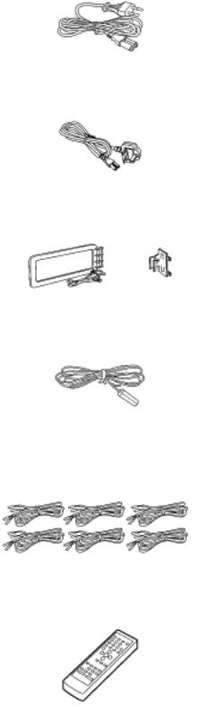
3 Accessories
TOP PREVIOUS NEXT |
|
AC power supply cord for (E),(EG) areas/(RJA0019-X)........................... |
1 pc. |
AC power supply cord for (EB) area/(RJA0053-2X)......................... |
1 pc. |
AM loop antenna set/(RSA0022-J)........................... |
1 pc. |
FM indoor antenna/(RSA0007).............................. |
1 pc. |
Speaker cords/(REE0499) |
..............................2 pcs./(REE0984).............................. |
2 pcs./ |
(REE0985).............................. |
2 pcs. |
|
Remote control transmitter/(RAK-EHA29WH)..................... |
1 pc. |
Remote control batteries/(R6/LR6,“AA”, UM-3)............ |
2 pcs. |
Note: These are available on sales route.
Antenna plug adaptor for (EB) area only/(SJP9009).............................. |
1 pc. |
•@
TOP PREVIOUS NEXT
4 Caution for AC Main Leads
TOP PREVIOUS NEXT

5 Location of Controls
TOP PREVIOUS NEXT
•@
TOP PREVIOUS NEXT
6 Operation Checks and Component
Replacement/Procedures
TOP PREVIOUS NEXT
This section describes procedures for checking the operation of the major printed circuit boards and replacing the main components.
For reassembly after operation checks or replacement, reverse the respective procedures. Special reassembly procedures are described only when required.
/
6.1 Checking for the AC IN P.C.B.
6.2 Checking for the operation P.C.B.
6.3 Checking for the main P.C.B.
6.4 Replacement for the regulator transistor
6.5 Replacement for the power IC
•@
TOP PREVIOUS NEXT
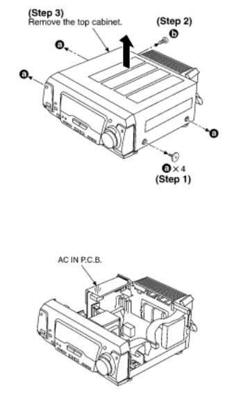
6.1 Checking for the AC IN P.C.B.
TOP PREVIOUS NEXT
Check the AC IN P.C.B. as shown below.
•@
TOP PREVIOUS NEXT
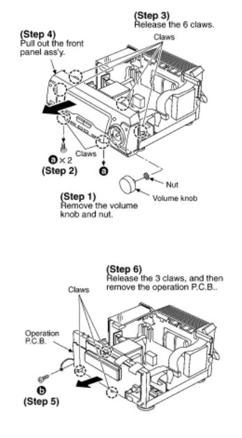
6.2 Checking for the operation P.C.B.
TOP PREVIOUS NEXT
Follow the (Step 1) - (Step 3) of item 6.1.
Check the operation P.C.B. as shown below.

•@
TOP PREVIOUS NEXT
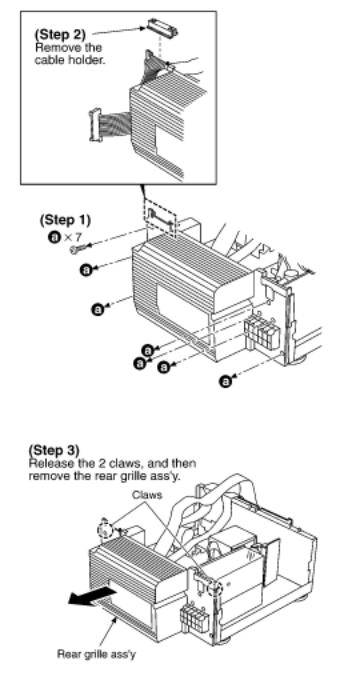
6.3 Checking for the main P.C.B.
TOP PREVIOUS NEXT
Follow the (Step 1) - (Step 3) of item 6.1.
Follow the (Step 1) - (Step 6) of item 6.2.
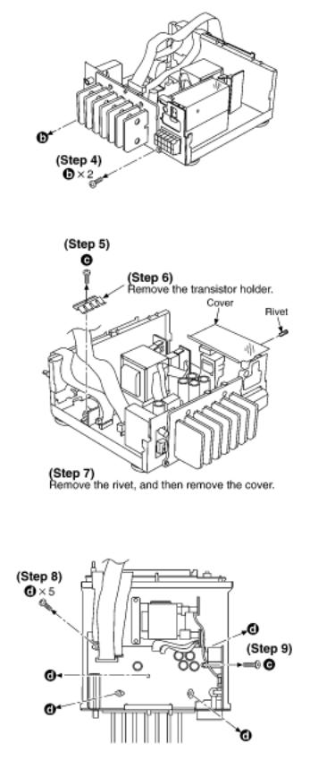
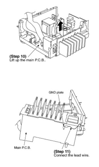
Check the main P.C.B. as shown below.
•@
TOP PREVIOUS NEXT
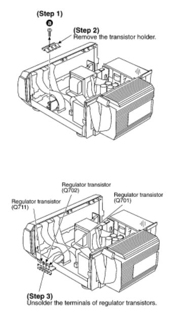
6.4 Replacement for the regulator transistor
TOP PREVIOUS NEXT
Follow the (Step 1) - (Step 3) of item 6.1.
•@
TOP PREVIOUS NEXT
6.5 Replacement for the power IC
TOP PREVIOUS NEXT
Follow the (Step 1) - (Step 3) of item 6.1.
Follow the (Step 1) - (Step 6) of item 6.2.
Follow the (Step 1) - (Step 10) of item 6.3.
•@
TOP PREVIOUS NEXT
7 To Supply Power Source
TOP PREVIOUS NEXT
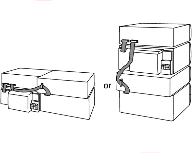
This unit SA-EH560 is designed to operate on power supplied form system connected./For system connection, refer to Fig. 7-1.
Fig. 7-1.
When the unit SA-EH560 has to test and service alone, use the following method to supply power source.
1.Short the section between W902A Pin 3 and C740 (-) (GND). (Refer to Fig. 7-2. )
2.Connect this unit to an AC power supply cord./(This unit come to stand-by mode.)
3.Turn the unit ON.
Fig. 7-2.

Notes:
Use only this method when checking the voltage etc../In case of checking the operations, use the system connections to supply power source.
•@
TOP PREVIOUS NEXT
8 Self-Diagnostic Mode
TOP PREVIOUS NEXT
This unit is equipped with a self-diagnostic function which, in the event of a malfunction, automatically displays a code indicating the nature of the malfunction.
Use this self-diagnostic function when servicing the unit.
8.1 To display the malfunction code
8.2 To return to the normal display
8.3 Display contents
8.3.1 U70 CD, U70 DECK(displayed automatically)
8.3.2 F61
•@
TOP PREVIOUS NEXT
8.1 To display the malfunction code
TOP PREVIOUS NEXT
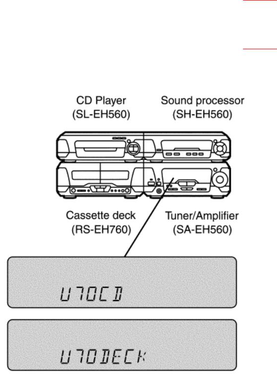
U70 CD:/U70 DECK:
Automatically displays on the tuner/amplifier when a malfunction occurs. Refer to Fig. 8-1.
F61:
Automatically displays on the tuner/amplifier when a malfunction occurs. Refer to Fig. 8-1.
Fig. 8-1.
•@
 Loading...