


 Loading...
AV Control Stereo Receiver
Operating Instructions
Model No. SA-DA10
SA-DA8
The photographs show the gold version of SA-DA8.
Model SA-DA10 is only for the United Kingdom.
The black version of SA-DA8 is only for the United Kingdom.
EB 
 GN
GN
Note:
“EB” on the packaging indicates the United Kingdom.
Before connecting, operating or adjusting this product, please read these instructions completely.
Please keep this manual for future reference.
RQT5518-B
Dear customer
Thank you for purchasing this product.
For optimum performance and safety, please read these instructions carefully.
These operating instructions are applicable to models
for the United Kingdom, Australia and New Zealand, however, are intended primarily for the United Kingdom model.
Table of contents |
|
|
Caution for AC Mains Lead ............................................. |
|
3 |
Safety precautions ........................................................... |
|
4 |
To enjoy surround sound ................................................ |
|
5 |
Front panel controls ......................................................... |
|
6 |
Concerning the remote control ....................................... |
|
9 |
Connections .................................................................... |
|
10 |
Connecting a DVD player .......................................................... |
|
10 |
Connecting video equipment ..................................................... |
|
11 |
Connecting audio equipment ..................................................... |
|
12 |
Antenna connections ................................................................. |
|
12 |
Connecting the AC mains lead and other information .............. |
13 |
|
Speaker connections ..................................................... |
|
14 |
Placement of speakers .............................................................. |
|
14 |
Connecting speakers ................................................................. |
|
15 |
Preparatory steps ........................................................... |
|
17 |
Speaker settings ........................................................................ |
|
17 |
Adjusting speaker output level .................................................. |
|
19 |
DSP sound modes .......................................................... |
|
20 |
Enjoying the sounds ...................................................... |
|
22 |
To enjoy bi-amp sound .............................................................. |
|
24 |
To adjust the tone quality .......................................................... |
|
25 |
To adjust the sound balance ..................................................... |
|
25 |
When using the VCR 3 terminals .............................................. |
|
25 |
Switching DVD analogue input ..................................... |
|
26 |
VGCA mode ..................................................................... |
|
27 |
The radio .......................................................................... |
|
28 |
Sequential tuning ....................................................................... |
|
28 |
Direct tuning ............................................................................... |
|
29 |
Preset tuning .............................................................................. |
|
30 |
RDS broadcasts Only for the United Kingdom |
............ |
32 |
To display RDS information ....................................................... |
|
32 |
PTY search and EON tuning ..................................................... |
|
33 |
About the PTY display ............................................................... |
|
35 |
Other functions ............................................................... |
|
36 |
To listen through headphones ................................................... |
|
36 |
Dynamic range compression ..................................................... |
|
36 |
To mute the sound level ............................................................ |
|
37 |
When using the unit in a darkened room .................................. |
|
37 |
The remote control ......................................................... |
|
38 |
To operate the receiver .............................................................. |
|
39 |
To operate a CD player or MD deck .......................................... |
|
41 |
To operate a cassette deck ....................................................... |
|
41 |
To watch TV broadcasts ............................................................ |
|
43 |
To watch video tapes ................................................................. |
|
43 |
To operate a DVD player ........................................................... |
|
45 |
To change the remote control code ........................................... |
|
46 |
Making a recording ......................................................... |
|
48 |
Recording on a tape deck or VCR ............................................. |
|
48 |
Timer function ................................................................. |
|
49 |
Setting the timers ....................................................................... |
|
49 |
Troubleshooting guide ................................................... |
|
50 |
The RESET function ....................................................... |
|
51 |
Maintenance .................................................................... |
|
51 |
Specifications .................................................. |
Back cover |
|
2
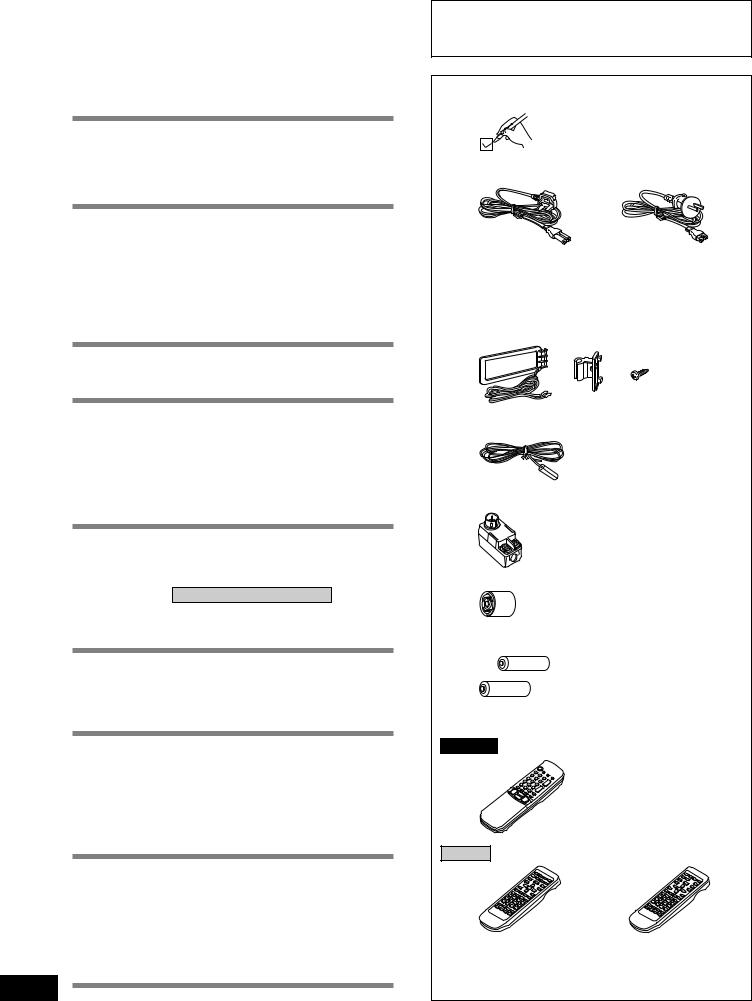
Supplied accessories
Please check and identify the supplied accessories.
M AC mains lead .................................................................... |
1 pc. |
For the United Kingdom |
For Australia and New Zealand |
(VJA0733) |
(RJA0035-X) |
M AM loop antenna set |
|
¡AM loop antenna ............................................................ |
1 pc. |
¡AM loop antenna holder ................................................. |
1 pc. |
¡Screw .............................................................................. |
1 pc. |
|
(RSA0012) |
MFM indoor antenna |
............................................................. 1 pc. |
|
(RSA0007) |
MAntenna plug ....................................................................... |
1 pc. |
|
Only for Australia and New Zealand |
|
(RFE0014) |
MAntenna plug ....................................................................... |
1 pc. |
|
Only for the United Kingdom |
|
(SJP9009) |
MBatteries ............................................................................ |
2 pcs. |
MRemote control ................................................................... |
1 pc. |
SA-DA10
Only for the United Kingdom (Gold model EUR51986) (Black model EUR51987)
SA-DA8
For the United Kingdom |
For Australia and New Zealand |
(EUR647136) |
(EUR647137) |
Use numbers indicated in parentheses when asking for replacement parts.
RQT5518
Caution for AC Mains Lead
(For United Kingdom)
(“EB” area code model only)
For your safety, please read the following text carefully.
This appliance is supplied with a moulded three pin mains plug for your safety and convenience.
A 5-ampere fuse is fitted in this plug.
Should the fuse need to be replaced please ensure that the replacement fuse has a rating of 5-ampere and that it is approved by ASTA or BSI to BS1362.
Check for the ASTA mark  or the BSI mark
  on the body of the fuse.
If the plug contains a removable fuse cover you must ensure that it is refitted when the fuse is replaced.
If you lose the fuse cover the plug must not be used until a replacement cover is obtained.
A replacement fuse cover can be purchased from your local dealer.
CAUTION!
I F T H E F I T T E D M O U L D E D P L U G I S UNSUITABLE FOR THE SOCKET OUTLET IN YOUR HOME THEN THE FUSE SHOULD BE REMOVED AND THE PLUG CUT OFF AND DISPOSED OF SAFELY.
THERE IS A DANGER OF SEVERE ELECTRICAL SHOCK IF THE CUT OFF PLUG IS INSERTED INTO ANY 13-AMPERE SOCKET.
If a new plug is to be fitted please observe the wiring code as stated below.
If in any doubt please consult a qualified electrician.
IMPORTANT
The wires in this mains lead are coloured in accordance with the following code:
Blue: Neutral, Brown: Live.
As these colours may not correspond with the coloured markings identifying the terminals in your plug, proceed as follows:
The wire which is coloured Blue must be connected to the terminal which is marked with the letter N or coloured Black or Blue.
The wire which is coloured Brown must be connected to the terminal which is marked with the letter L or coloured Brown or Red.
WARNING: DO NOT CONNECT EITHER WIRE TO THE EARTH TERMINAL WHICH IS MARKED WITH THE LETTER E, BY THE EARTH SYMBOL  OR COLOURED GREEN OR GREEN/YELLOW.
THIS PLUG IS NOT WATERPROOF–KEEP DRY.
Before use
Remove the connector cover.
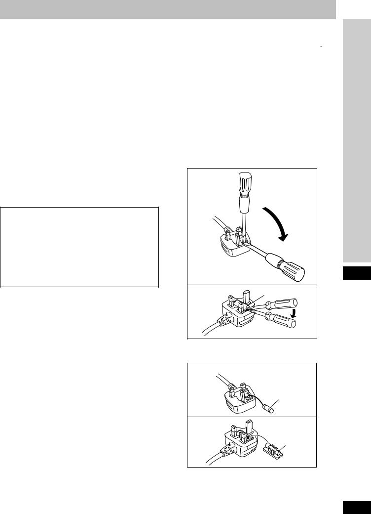
How to replace the fuse
The location of the fuse differ according to the type of AC mains plug (figures A and B). Confirm the AC mains plug fitted and follow the instructions below.
Illustrations may differ from actual AC mains plug.
1. Open the fuse cover with a screwdriver.
Figure A
Before use
Figure B |
Fuse cover |
2.Replace the fuse and close or attach the fuse cover.
Figure A
Fuse
(5 ampere)
Figure B
Fuse
(5 ampere)
3
RQT5518
Safety precautions
Placement
Set the unit up on an even surface away from direct sunlight, high temperatures, high humidity, and excessive vibration. These conditions can damage the cabinet and other components, thereby shortening the unit’s service life.
Place it at least 15 cm away from wall surfaces to avoid distortion and unwanted acoustical effects.
Do not place heavy items on the unit.
Voltage
Do not use high voltage power sources. This can overload the unit and cause a fire.
Do not use a DC power source. Check the source carefully when setting the unit up on a ship or other place where DC is used.
AC mains lead protection
Ensure the AC mains lead is connected correctly and not damaged. Poor connection and lead damage can cause fire or electric shock. Do not pull, bend, or place heavy items on the lead. Grasp the plug firmly when unplugging the lead. Pulling the AC mains lead can cause electric shock.
Do not handle the plug with wet hands. This can cause electric shock.
Foreign matter
Do not let metal objects fall inside the unit. This can cause electric shock or malfunction.
Do not let liquids get into the unit. This can cause electric shock or malfunction. If this occurs, immediately disconnect the unit from the power supply and contact your dealer.
Do not spray insecticides onto or into the unit. They contain flammable gases which can ignite if sprayed into the unit.
Service
Do not attempt to repair this unit by yourself. If sound is interrupted, indicators fail to light, smoke appears, or any other problem that is not covered in these instructions occurs, disconnect the AC mains lead and contact your dealer or an authorized service center. Electric shock or damage to the unit can occur if the unit is repaired, disassembled or reconstructed by unqualified persons.
Extend operating life by disconnecting the unit from the power source if it is not to be used for a long time.
4
CAUTION!
DO NOT INSTALL OR PLACE THIS UNIT IN A BOOKCASE, BUILT IN CABINET OR IN ANOTHER CONFINED SPACE. ENSURE THE UNIT IS WELL VENTILATED. ENSURE THAT CURTAINS AND ANY OTHER MATERIALS DO NOT OBSTRUCT THE VENTILATION TO PREVENT RISK OF ELECTRIC SHOCK OR FIRE HAZARD DUE TO OVERHEATING.
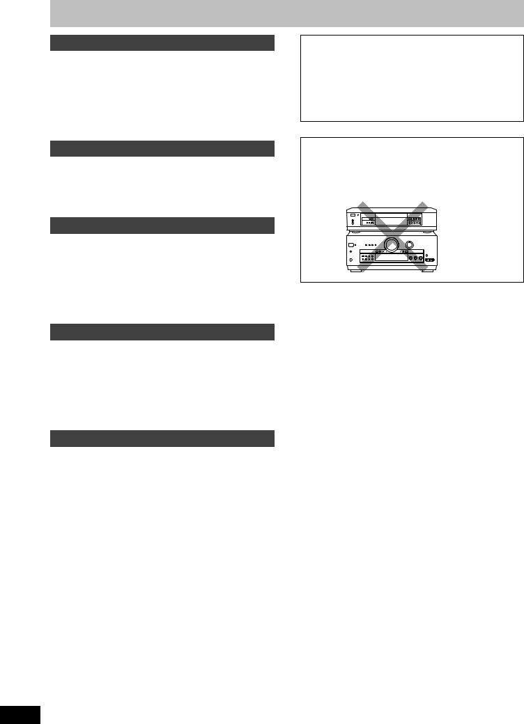
CAUTION
Do not place anything on top of this unit or block the heat radiation vents in any way. In particular, do not place tape decks or CD/DVD players on this unit as heat radiated from it can damage your software.
NO
RQT5518
To enjoy surround sound
Do the connections, settings, and adjustments in the order shown to enjoy surround sound.
Be sure to make the correct speaker settings. If, for example, you have not connected a center speaker and you leave the initial setting value of LARGE as it is, then dialog and other sounds may not be reproduced.
Connect the equipment
(a Pages 10–13.)
Position and connect the speakers
(a Pages 14–16.)
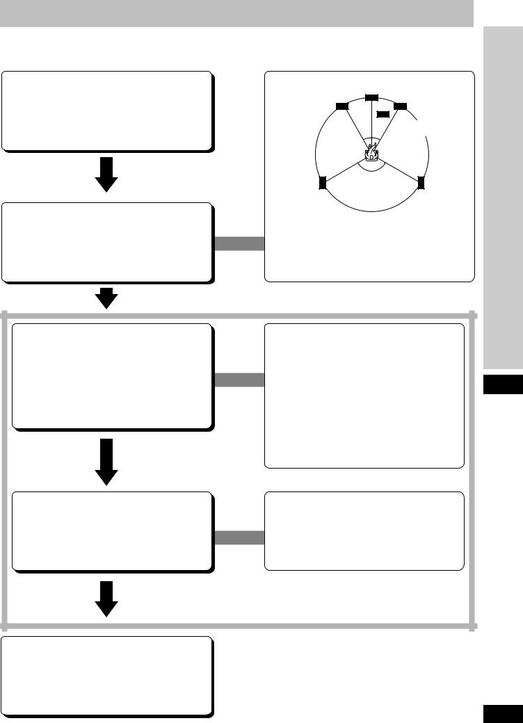
Front speaker (left)
(not included)
Center speaker |
|
|
(not included) |
Front speaker |
|
|
(right) |
|
|
(not included) |
|
30° 30° |
Subwoofer |
|
(not included) |
||
|
30° 30° |
120° |
Surround speaker |
120° |
Surround speaker |
|
||
(left) |
|
(right) |
(not included) |
|
(not included) |
The front, center, and surround speakers should be placed at approximately the same distance from the listening position. The angles in the diagram are approximate.
Set the presence and type (small/large), distance and filter of the speakers you have connected
(a Pages 17–18.)
Adjust the level for the speakers
(a Page 19.)
In SIZE
Select LARGE or SMALL for the front speakers
Select LARGE, SMALL, or NONE for the center and surround speakers
Select YES or NO for the subwoofer
In DISTANCE
Enter the distance of the front, center, and surround speakers from the listening position
In FILTER
Enter the cutoff frequency for your subwoofer based on the bass capability of your front speakers
While sitting in the usual listening position, use the test signal to adjust the volume of the speakers to the same
apparent level.
When using DVD 6CH INPUT mode
These settings need to be changed on the player. Read the player’s instructions for setting details.
Before use
Sit back and enjoy the experience
(a Pages 22–23.)
5
RQT5518
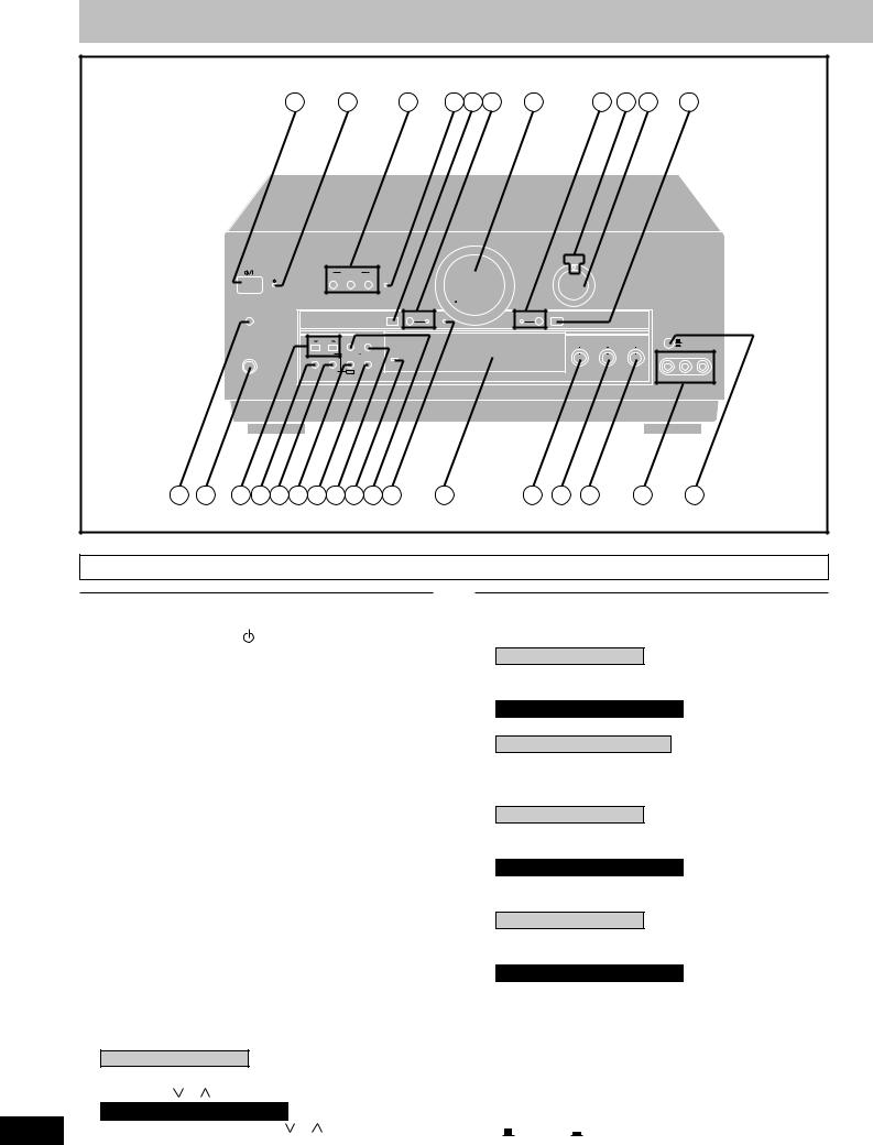
Front panel controls
|
|
|
1 |
|
2 |
|
3 |
4 |
5 |
6 |
7 |
|
8 |
9 |
10 |
11 |
|
|
|
|
|
|
|
|
|
|
|
|
VOLUME |
|
|
|
|
|
|
|
|
|
|
|
|
|
|
|
|
|
|
DIGITAL |
|
|
|
|
|
|
|
|
|
|
|
|
|
|
|
|
|
|
INPUT SELECTOR |
|
|
||
|
|
|
|
|
SPEAKERS |
|
|
|
|
|
|
|
|
|
|
|
|
|
|
|
|
A |
B |
BI-WIRE BI-AMP |
|
|
|
|
|
|
|
|
|
|
|
|
|
|
|
|
|
|
MIN |
|
|
|
MAX |
|
|
|
|
|
|
|
|
TIMER |
|
|
|
|
DVD 6CH INPUT VGCA |
VIA TONE |
|
|
TAPE MONITOR |
DIGITAL INPUT |
|
|
|
|
|
|
|
|
|
|
|
|
ON |
|
|
|
|
|
|
|
|
|
|
|
|
-MODE |
|
|
|
|
|
|
|
|
|
|
|
|
|
|
|
|
|
–TIME |
|
|
|
|
|
|
|
|
|
|
|
|
|
|
|
|
|
|
TUNING |
PRESET |
MEMORY |
|
|
|
|
|
|
BASS |
TREBLE |
BALANCE |
VCR 2 |
||
|
|
|
|
|
|
|
|
|
|
|
|
|
VCR 3 |
||||
|
|
PHONES |
PTY SELECTOR |
DISPLAY MODE PTY SEARCH |
WAKE |
|
|
|
|
|
|
|
|
|
VCR 3 |
||
|
|
BAND |
FM MODE |
DSP SOUND MODE |
|
|
|
|
|
|
|
|
|
|
|||
|
|
|
|
|
|
|
|
|
|
|
|
|
|
||||
|
|
|
|
|
|
|
|
|
|
|
|
MIN |
MAX MIN |
MAX |
L |
R |
|
|
|
|
|
EON |
RDS |
|
|
|
|
|
|
|
|
|
|
|
|
|
|
|
|
|
|
|
|
|
|
|
|
|
|
|
|
VIDEO IN |
L AUDIO IN R |
12 |
13 |
14 15 16 17 18 19 20 21 22 |
23 |
|
|
24 |
25 |
26 |
|
|
27 |
28 |
|||||
Main unit
No. |
Name |
Ref.page |
|
No. |
Name |
Ref.page |
q Standby/on switch ( /l) .................................. |
17 |
Press to switch the unit from on to standby mode or vice versa.
In standby mode, the unit is still consuming a small amount of power.
w Standby indicator (  )
)
When the unit is connected to the AC mains supply, this indicator lights up in standby mode and goes out when the unit is turned on.
|
e Speaker select buttons |
|
|
(SPEAKERS, A, B, BI-WIRE) ...................... |
17, 22 |
|
r Bi-amp indicator (BI-AMP) ............................... |
24 |
|
t DVD 6CH input select button |
|
|
(DVD 6CH INPUT) .............................................. |
26 |
|
y VGCA mode select button/indicator |
|
|
(VGCA, ON) ........................................................ |
27 |
|
u Volume control (VOLUME) ............................... |
23 |
|
i Tape monitor button/indicator |
|
|
(TAPE MONITOR) .............................................. |
24 |
|
o Digital input indicator (DIGITAL) ..................... |
22 |
|
!0Input selector (INPUT SELECTOR) ........... |
17, 22 |
|
!1Digital input select button |
|
|
(DIGITAL INPUT) ............................................... |
22 |
|
!2Timer button (TIMER, -MODE, –TIME) ............ |
49 |
|
!3Headphones jack (PHONES) ........................... |
36 |
|
!4For the United Kingdom |
|
|
Tuning/PTY select buttons |
|
|
(TUNING, , , PTY SELECTOR) ........... |
28, 33 |
|
For Australia and New Zealand |
|
6 |
Tuning buttons (TUNING, , ) ................... |
28 |
!5Band select button (BAND) ............................. |
28 |
!6For the United Kingdom |
|
FM mode select/EON button |
|
(FM MODE, EON) ......................................... |
28, 34 |
For Australia and New Zealand |
|
FM mode select button (FM MODE) ................ |
28 |
!7Only for the United Kingdom |
|
RDS button (RDS) ............................................. |
32 |
!8DSP sound mode select button |
|
(DSP SOUND MODE) ........................................ |
22 |
!9For the United Kingdom |
|
Memory/PTY search button |
|
(MEMORY, PTY SEARCH) .......................... |
30, 33 |
For Australia and New Zealand |
|
Memory button (MEMORY) .............................. |
30 |
@0Wake indicator (WAKE) .................................... |
49 |
@1For the United Kingdom |
|
Preset channel/Display mode select button |
|
(PRESET, DISPLAY MODE) ....................... |
31, 32 |
For Australia and New Zealand |
|
Preset channel button (PRESET) .................... |
31 |
@2Via tone indicator (VIA TONE) ......................... |
27 |
@3Display section ................................................... |
7 |
@4Bass control (BASS) ......................................... |
25 |
@5Treble control (TREBLE) .................................. |
25 |
@6Balance control (BALANCE) ............................ |
25 |
@7VCR 3 terminals (VCR 3) .................................. |
11 |
@8VCR 2/VCR 3 select button |
|
( VCR 2, VCR 3) .......................................... |
25 |
RQT5518
|
|
29 |
30 |
31 |
32 |
33 |
34 |
35 |
36 |
37 |
38 |
39 40 |
|
41 |
|
|
|
TUNED STEREO |
RDS |
PS |
PTY |
RT |
EON |
|
SLEEP |
M |
PROGRAM FORMAT |
||||
|
|
WAKE MONO |
|
|
|
|
|
|
|
|
|
L |
|
C |
R |
|
|
|
|
|
|
|
|
|
|
|
kHz |
|
|||
|
|
|
|
|
|
|
|
|
|
|
LS |
S |
LFE |
RS |
|
|
|
LOW IMP |
|
|
|
|
|
|
|
|
MHz |
||||
|
|
SPEAKERS |
SUB- |
|
DIGITAL |
|
|
PRO LOGIC AAC |
|
SOUND MODE |
|
||||
|
|
A B BI-WIRE |
WOOFER |
|
|
|
STEREO SURROUND SFC |
||||||||
42 |
43 |
44 |
|
|
|
|
45 |
|
|
|
|
46 |
|
|
|
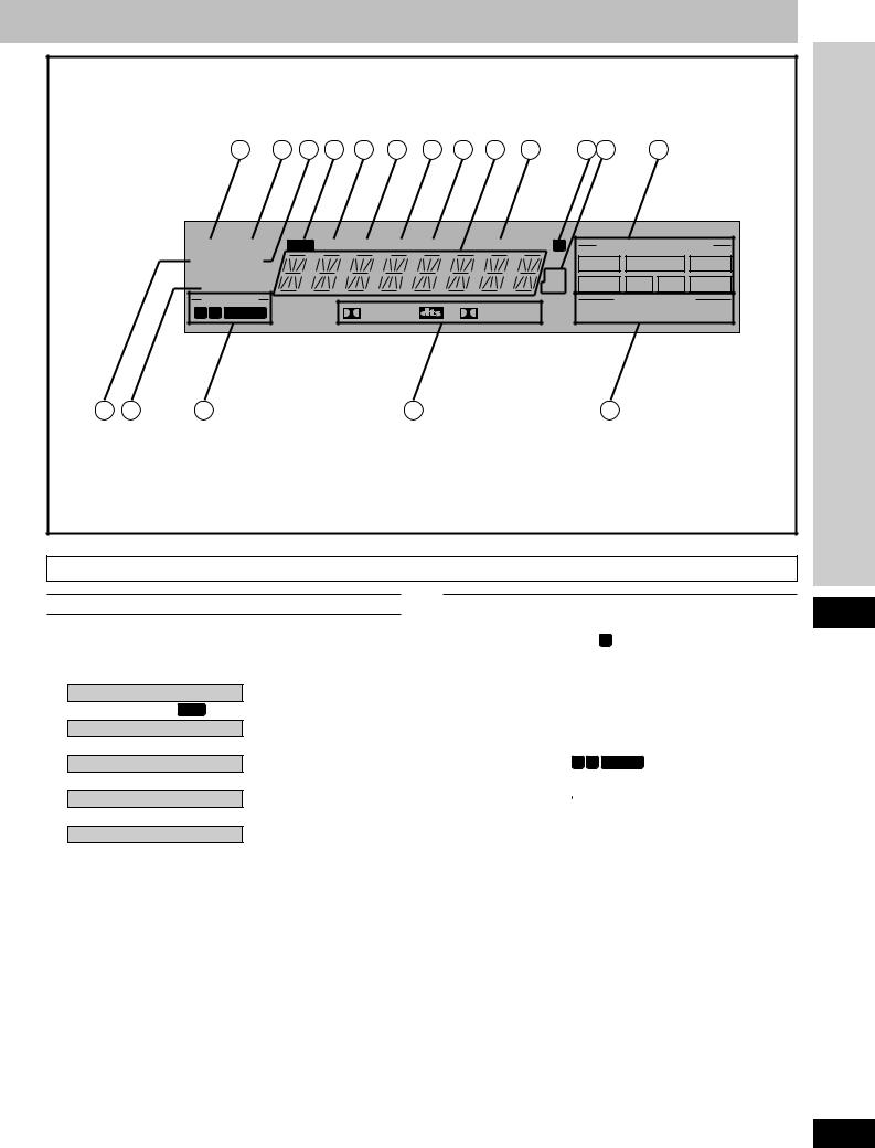
Display section
No. |
Name |
Ref.page |
@9Tuned indicator (TUNED) ................................. |
28 |
|
#0Stereo indicator (STEREO) .............................. |
28 |
|
#1Monaural indicator (MONO) ............................. |
28 |
|
#2Only for the United Kingdom |
|
|
RDS indicator ( RDS ) ........................................ |
32 |
|
#3Only for the United Kingdom |
|
|
PS indicator (PS) ............................................... |
32 |
|
#4Only for the United Kingdom |
|
|
PTY indicator (PTY) .......................................... |
32 |
|
#5Only for the United Kingdom |
|
|
RT indicator (RT) ............................................... |
32 |
|
#6Only for the United Kingdom |
|
|
EON indicator (EON) ......................................... |
34 |
|
#7Display |
|
|
#8Sleep indicator (SLEEP) ................................... |
49 |
|
No. |
|
Name |
|
|
|
|
Ref.page |
||
#9Memory indicator ( M ) ...................................... |
30 |
||||||||
$0Frequency unit indicator (kHz, MHz) .............. |
28 |
||||||||
$1Program format indicators |
|
||||||||
(PROGRAM FORMAT, L, C, R, LS, S, LFE, RS) ...... |
20 |
||||||||
$2Wake indicator (WAKE) .................................... |
49 |
||||||||
$3Low impedance indicator (LOW IMP) ............. |
24 |
||||||||
$4Front speaker indicator |
|
||||||||
(-SPEAKERS-, |
A B BI-WIRE ) .............................. |
22 |
|||||||
$5Signal format indicators |
|
||||||||
( |
|
DIGITAL, |
|
|
, |
|
|
PRO LOGIC) |
20 |
|
|
|
|
|
|||||
$6DSP sound mode indicators |
|
||||||||
(SOUND MODE, STEREO, SURROUND, SFC) ....... |
20 |
||||||||
Before use
7
RQT5518
SA-DA10 |
|
|
|
|
|
|
|
47 |
|
TV |
|
VCR |
|
DVD |
|
|
|
|
|
|
|
|
|
48 |
TAPE |
CD |
TUNER/BAND CH |
|
|||
|
|
|
|
|
|
55 |
|
|
1 |
2 |
|
3 |
|
|
|
|
|
|
|
|
|||
49 |
|
|
|
|
|
VOLUME |
|
4 |
5 |
|
6 |
|
+ |
56 |
|
|
7 |
8 |
|
9 |
|
– |
|
|
|
|
57 |
||||
|
DIRECT TUNING/ |
|
≥10/ENTER |
|
|||
50 |
DISC ENTER |
|
MUTING |
||||
|
0 |
|
-/-- |
|
|
58 |
|
48 |
DISC/DECK 1/2 |
MD |
SOUND MODE |
SFC |
59 |
||
51 |
|
|
|
|
|
|
60 |
52 |
|
|
|
|
|
|
|
|
DVD |
|
SLOW/ |
|
|
|
|
|
|
|
|
DELAY |
|
||
|
|
|
SEARCH |
|
|
||
|
TOP MENU |
|
|
MENU |
|
LEVEL |
|
53 |
|
ENTER |
|
|
+ |
61 |
|
|
DISPLAY |
|
|
RETURN |
– |
|
|
|
SUB TITLE |
AUDIO |
ANGLE |
|
TEST |
62 |
|
|
|
– PAGE + |
|
|
|||
|
GROUP |
|
DIMMER |
63 |
|||
|
|
|
|
|
|
|
|
54 |
–TV VOL + |
|
TV/AV |
|
DVD 6CH |
64 |
|
|
|
|
|
|
|
||
|
|
|
|
|
|
|
65 |
SA-DA8 |
|
|
|
|
|
|
|
|
|
TV |
|
VCR |
|
TUNER/ |
|
66 |
|
|
|
BAND |
|
||
|
TAPE |
MD |
|
CD |
74 |
||
|
|
|
|||||
67 |
|
|
|
|
|
|
|
68 |
TOP MENU |
|
|
|
|
DVD |
|
DISC/DECK |
ENTER |
|
|
|
|||
|
1/2 |
|
|
|
|||
|
|
|
|
|
|
|
|
|
DISPLAY |
|
|
|
|
MENU |
75 |
69 |
STEREO SURROUND |
SFC |
|
TEST |
76 |
||
|
|
|
|
|
|
||
|
DELAY |
LEVEL |
– |
|
+ |
||
|
|
77 |
|||||
|
1 |
2 |
|
3 |
DIRECT TUNING/ |
||
|
|
|
|||||
|
|
|
DISC ENTER |
|
|||
70 |
4 |
5 |
|
6 |
|
≥10/–/– – |
78 |
|
|
79 |
|||||
7 |
8 |
|
9 |
|
0 |
||
|
|
|
|
||||
71 |
TV VOL |
|
TV/AV |
DVD 6CH |
80 |
||
|
|
|
|
|
|
||
72 |
DIMMER MUTING |
– VOL + |
81 |
||||
|
|
|
|
|
|
82 |
|
73 |
|
|
|
|
|
|
|
8 |
|
|
|
|
|
|
|
RQT5518 |
|
|
|
|
|
|
|
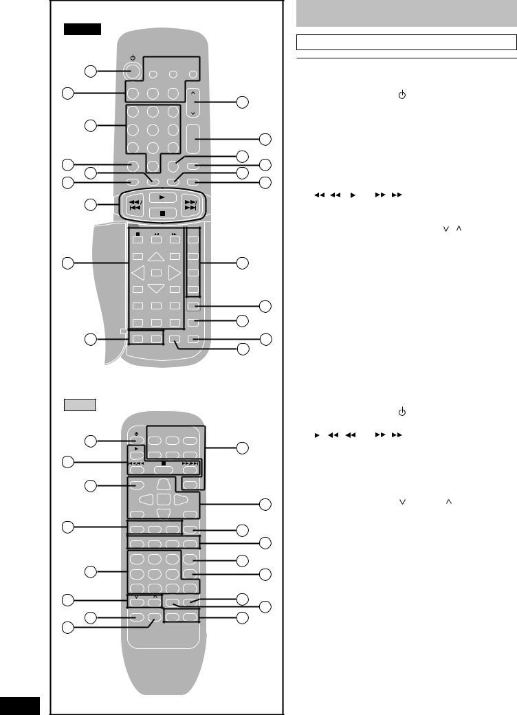
Front panel controls
Remote control
No. |
|
|
|
Name |
|
|
|
|
Ref.page |
|||||||
|
|
|
|
|
|
|
|
|
|
|
|
|
|
|
|
|
SA-DA10 |
|
|
|
|
|
|
|
|
|
|
|
|
|
|||
$7Standby/on button ( |
) .................................... |
|
|
|
39 |
|
||||||||||
$8Input select buttons |
|
|
|
|
|
|
|
|||||||||
|
(TV, VCR, DVD, TAPE, CD, TUNER/BAND, MD) |
..... 39 |
|
|||||||||||||
$9Numbered buttons ...................................... |
|
|
|
|
|
29, 39 |
||||||||||
%0Direct tuning/disc enter button |
|
|
|
|
||||||||||||
|
(DIRECT TUNING/DISC ENTER) ................ |
|
29, 39 |
|
||||||||||||
%1Disc/deck 1/2 select button |
|
|
|
|
||||||||||||
|
(DISC/DECK 1/2) |
................................................ |
|
|
|
|
|
|
41 |
|
||||||
%2Disc and deck operation buttons |
|
|
|
|||||||||||||
( |
/ |
|
, |
, |
|
, |
/ |
|
|
) |
|
|
|
41 |
|
|
|
|
|
|
|
|
|||||||||||
%3DVD player operation buttons ......................... |
|
|
45 |
|||||||||||||
%4TV volume buttons (–TV VOL+) ....................... |
|
|
43 |
|||||||||||||
%5Channel up/down ...............button (CH, , |
) |
|
39 |
|
||||||||||||
%6Volume buttons ..............(VOLUME, +, –) |
|
|
19, 39 |
|||||||||||||
%7³10/ENTER, -/– – button |
|
|
|
|
||||||||||||
|
(³10/ENTER, -/– –) ............................................. |
|
|
|
|
|
39 |
|||||||||
%8Muting button (MUTING) ............................ |
|
|
37, 39 |
|||||||||||||
%9DSP sound mode select button |
|
|
|
|
||||||||||||
|
(SOUND MODE) ................................................. |
|
|
|
|
|
|
|
39 |
|||||||
^0SFC mode select ..................button (SFC) |
|
|
23, 39 |
|
||||||||||||
^1Delay time/level adjust buttons |
|
|
|
|
||||||||||||
|
(DELAY, LEVEL, +, –) ........................... |
|
19, 23, 39 |
|||||||||||||
^2Test button (TEST) ...................................... |
|
|
|
|
|
19, 39 |
||||||||||
^3Dimmer button (DIMMER) .......................... |
|
|
37, 39 |
|||||||||||||
^4DVD 6CH input select button |
|
|
|
|
||||||||||||
|
(DVD 6CH) |
.......................................................... |
|
|
|
|
|
|
|
|
|
39 |
||||
^5TV/AV select ............................button (TV/AV) |
|
|
43 |
|
||||||||||||
|
|
|
|
|
|
|
|
|
|
|
|
|
|
|
|
|
SA-DA8 |
|
|
|
|
|
|
|
|
|
|
|
|
|
|
||
^6Standby/on button ( .................................... |
) |
|
|
|
39 |
|
||||||||||
^7Disc and deck operation buttons |
|
|
|
|||||||||||||
( |
, |
|
|
/ |
, |
|
, |
/ |
|
|
) |
|
|
|
41 |
|
|
|
|
|
|
|
|
||||||||||
|
|
|
|
|
|
|
||||||||||
^8Disc/deck 1/2 select button |
|
|
|
|
||||||||||||
|
(DISC/DECK 1/2) ................................................ |
|
|
|
|
|
|
|
41 |
|
||||||
^9DSP sound mode and SFC mode select |
|
|
||||||||||||||
|
buttons (STEREO, SURROUND, SFC) ...... |
|
23, 39 |
|||||||||||||
&0Numbered ......................................buttons |
|
|
|
|
|
29, 39 |
||||||||||
&1TV volume ...................buttons ( |
|
TV VOL |
) |
|
43 |
|
||||||||||
&2Dimmer button ...........................(DIMMER) |
|
|
37, 39 |
|||||||||||||
&3Muting button ............................(MUTING) |
|
|
37, 39 |
|||||||||||||
&4Input select buttons |
|
|
|
|
|
|
|
|||||||||
|
For the United Kingdom |
|
|
|
|
|
|
|
|
|||||||
|
(TV, VCR, TUNER/BAND, ..... |
TAPE, MD, CD, DVD) |
39 |
|
||||||||||||
|
For Australia and New Zealand |
|
|
|
|
|
||||||||||
|
(TV, VCR, TUNER/BAND, ..... |
TAPE, CD, DVD) |
39 |
|
||||||||||||
&5DVD player .........................operation buttons |
|
|
45 |
|||||||||||||
&6Test button ......................................(TEST) |
|
|
|
|
|
19, 39 |
||||||||||
&7Delay time/level adjust buttons |
|
|
|
|
||||||||||||
|
(DELAY, LEVEL, –, +) ........................... |
|
19, 23, 39 |
|||||||||||||
&8Direct tuning/disc enter button |
|
|
|
|
||||||||||||
|
(DIRECT TUNING/DISC ENTER) ................ |
|
29, 39 |
|
||||||||||||
&9³10/-/– – ................................button³(10/-/– –) |
|
|
39 |
|||||||||||||
*0DVD 6CH input select button |
|
|
|
|
||||||||||||
|
(DVD 6CH) .......................................................... |
|
|
|
|
|
|
|
|
|
|
39 |
||||
*1TV/AV select ............................button (TV/AV) |
|
|
43 |
|
||||||||||||
*2Volume buttons ..........................(– VOL +) |
|
|
19, 39 |
|||||||||||||
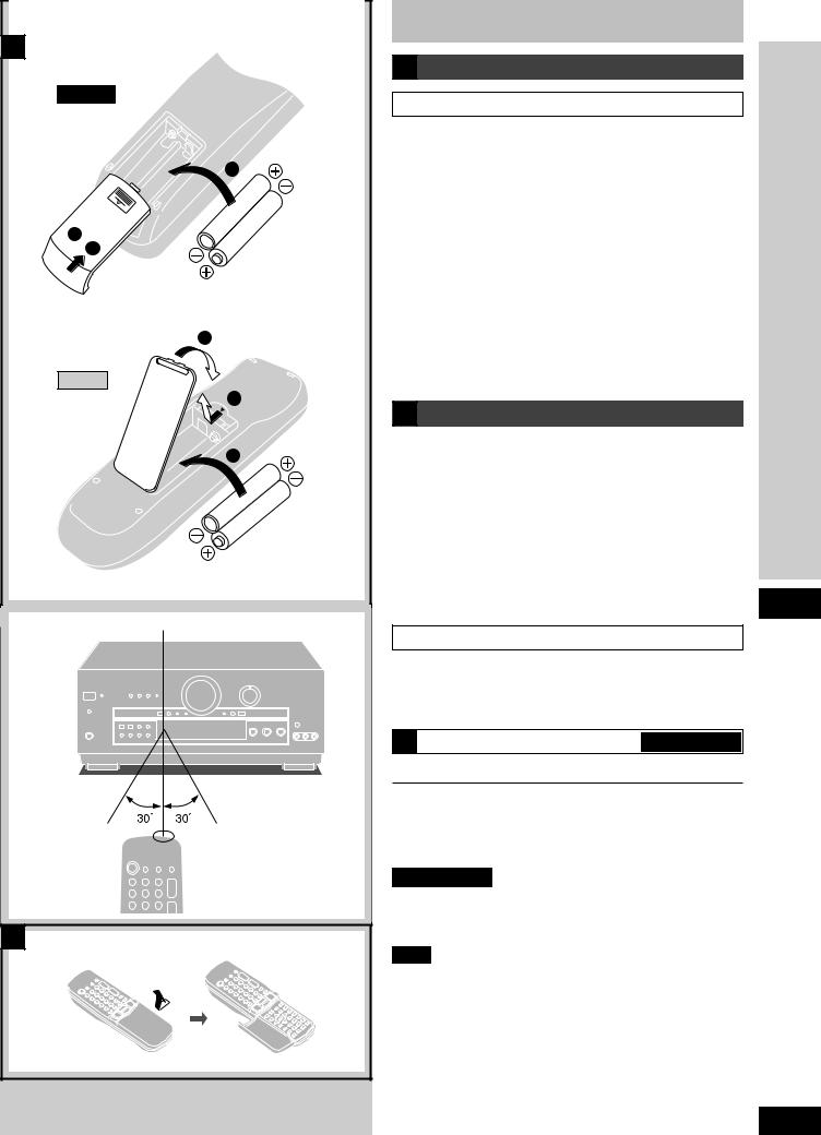
A
SA-DA10
2
1  3
3
(R6, AA, UM-3)
3
SA-DA8
1
2
(R6, AA, UM-3)
B |
Remote control signal sensor |
Transmission |
|
About 7 meters in front of the |
||
window |
|
|||
|
|
|
signal sensor. (The actual |
|
|
|
|
range will depend on the |
|
|
|
|
angle at which the remote |
|
|
|
|
control is used.) |
|
|
|
|
|
|
|
|
|
|
|
C
Concerning the remote control
A Battery installation
Use of batteries
¡Align the poles (+ and –) properly when inserting the batteries. Press in and down towards the minus end.
¡Do not mix old and new batteries or different types of batteries.
¡Do not recharge ordinary dry cell batteries.
¡Do not heat or disassemble the batteries. Do not allow them to contact flame or water.
¡Remove the batteries if the unit is not to be used for a long time. ¡Do not keep together with metallic objects such as necklaces.
¡Do not use rechargeable type batteries.
¡Do not use batteries if the covering has been peeled off.
Mishandling of batteries can cause electrolyte leakage which can damage items the fluid contacts and may cause a fire.
If electrolyte leaks from the batteries, consult your dealer.
Wash thoroughly with water if electrolyte comes in contact with any part of your body.
B Correct method of use
|
|
|
use |
Operation notes |
|
|
|
|
|
|
|
|
|
|
Before |
¡Do not place obstacles between the remote control |
signal |
||
the remote control unit free from dust. |
|
|
|
sensor and remote control unit. |
|
|
|
¡Do not expose the remote control signal sensor to direct sunlight or to the bright light of a fluorescent light.
¡Take care to keep the remote control signal sensor and end of
¡If the unit is installed in a rack with glass doors, the glass doors’ thickness or color might make it necessary to use the remote control a shorter distance from the unit.
To prevent damage
¡Never place heavy items on top of the unit.
¡Do not disassemble or reconstruct the unit.
¡Do not spill water or other liquids into the unit.
C How to open the remote control SA-DA10 only
For your reference
This remote control can be used to operate the receiver you purchased and some other Panasonic and Technics cassette decks, MD decks, CD players, TVs, VCRs and DVD players, provided they are equipped with a remote control sensor.
SA-DA10 only
It is also possible to change-over the remote control code so that the remote control can operate TVs, VCRs and DVD players which have not been manufactured by this company (a pages 46–47).
Note
¡For details on operating other equipment, see the instruction manual provided with specific unit.
¡Some models cannot be operated by this remote control. ¡Actual operations depend on your equipment and software.
9
RQT5518
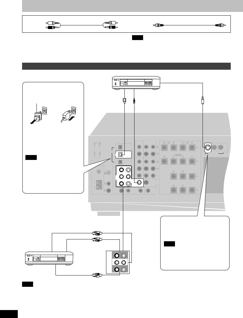
Connections
Stereo phono cable (not included)
White (L)
Red (R)
Video connection cable (not included)
Turn off all components before making any connections.
To connect equipment, refer to the appropriate operating instructions.
Note
¡Use digital connection to enjoy Dolby Digital or DTS
(\ page 20).
¡Use analogue connection to enjoy sources that cannot be decoded on this unit and to record a source (a pages 22 and 48).
Connecting a DVD player
DVD player (not included)
S-VIDEO OUT
Optical fiber cable |
DIGITAL OUT |
VIDEO OUT |
|
connection |
|||
|
|
||
Dust cap |
|
|
¡Do not bend the optical fiber cable. ¡If the digital optical connector is not going to be used, be sure to attach the dust cap to prevent exposure to
dust.
Note
Dolby Digital RF (radio frequency) signals cannot be decoded with this unit.
|
CD |
TAPE/MD |
|
|
L FRONT R |
|
|
|
|
|
|
|
|
REC |
PLAY |
R |
B |
A |
L |
IN |
IN |
MONITOR |
|
|
OPTICAL |
(OUT) |
(IN) |
|
|
|
|
|
|||
|
|
|
|
|
|
|
|
|
|
OUT |
|
|
|
|
|
|
|
|
|
|
|
|
|
LOOP ANT |
CD |
|
L |
|
|
|
|
|
+ |
|
|
HOLDER |
|
|
|
|
|
|
|
|
|
|
|
|
|
DIGITAL OPTICAL |
|
|
|
|
|
|
|
DVD VCR |
||
|
|
|
DVD |
|
|
|
|
|
R |
LF BI-WIRE |
HF |
S-VIDEO |
|
|
|
|
|
|
|
|
|
R |
L |
R |
L |
|
|
|
OPTICAL |
|
|
VCR 2 |
|
VCR 1 |
|
|
|
|
|
|
|
TV |
|
|
|
|
|
L |
|
|
– |
|
PHONO |
|
FRONT |
|
IN |
OUT |
IN |
|
|
|
||
FM |
R |
L |
|
|
|
|
|
|
||||
|
|
|
|
|
|
|
|
|||||
ANT |
GND |
|
|
|
|
|
|
|
R |
|
|
|
|
|
|
|
|
|
|
|
|
R SURROUND L |
CENTER |
||
75 Ω |
|
|
SUBWOOFER CENTER |
IN |
OUT |
IN |
||||||
|
|
|
|
SPEAKERS |
|
|
|
|||||
|
|
|
IN |
|
|
|
|
|
|
|
|
+ |
|
|
|
DVD/ |
|
|
|
|
|
|
|
|
|
|
|
|
DVD 6CH |
|
|
|
|
|
|
|
|
|
|
|
|
SURROUND SURROUND |
|
|
|
|
|
|
|||
|
|
|
R |
|
|
L |
|
|
SUBWOOFER |
|
|
|
|
L |
|
|
|
|
|
|
|
|
|
|
|
LOOP |
|
|
|
|
|
IN |
|
OUT |
R |
L |
|
|
|
|
|
|
|
|
|
|
|
||||
EXT |
|
|
|
|
|
|
|
|
|
|
|
|
AM |
R |
|
TV |
|
|
|
|
|
TV |
|
|
– |
ANT |
|
|
R |
|
IN |
L |
IN |
|
MONITOR OUT |
|
|
|
|
|
|
|
|
|
|
|
|||||
To connect analogue 6 channel |
|
AUDIO OUT |
|
(CENTER) |
AUDIO OUT |
(SUBWOOFER) |
(FRONT L,R) |
|
R |
FRONT |
L |
|
SUBWOOFER CENTER |
||
|
IN |
|
|
|
DVD/ |
|
|
|
DVD 6CH |
|
|
AUDIO OUT |
SURROUND SURROUND |
||
R |
|
L |
|
(SURROUND L,R)
Note
Connect to FRONT L, R if your DVD player does not have 6 channel output.
The S-VIDEO terminals
Connections through these terminals provide higher quality pictures than through the video terminal.
Note
When using S-VIDEO terminals, be aware that video signals input into the
VIDEO terminals cannot be output from S-VIDEO terminals or vice versa.
10
RQT5518
|
|
|
|
|
|
|
|
|
|
|
|
|
Optical fiber cable (not included) |
S-VIDEO cable (not included) |
|||
|
|
|
|
|
|
|
|
|
|
|
|
Connecting video equipment
VCR (for play only) (not included) |
VCR (not included) |
|
|||
|
|
|
AUDIO |
|
S-VIDEO OUT |
AV IN |
|
|
|
|
|
|
|
IN |
|
AV IN |
|
|
|
|
|
||
|
|
|
|
|
|
21pin scart cable |
VIDEO |
AUDIO |
AUDIO VIDEO |
VIDEO |
|
(not included) |
OUT |
OUT |
OUT |
OUT |
IN |
(VIDEO OUT) |
|
|
|
|
21pin scart cable |
|
|
|
|
(not included) |
|
(AUDIO OUT)


(VIDEO IN) (VIDEO OUT)
|
|
|
|
|
|
|
|
|
or |
|
|
|
|
|
|
or |
|
|
(AUDIO OUT) |
|
|
|
|
|
|
|
|
|
|
|
|
|
|
|
|
|
|
|
|
|
|
|
|
|
|
|
|
|
|
|
|
|
|
|
|
|
|
|
(AUDIO IN) |
|
|
|
|
|
|
|
CD |
|
TAPE/MD |
|
|
L FRONT R |
|
|
|
|
|
||
|
|
|
|
|
|
|
|
|
REC |
PLAY |
R |
B |
A |
L |
IN |
IN |
MONITOR |
||
|
|
|
OPTICAL |
|
|
|
|
(OUT) |
(IN) |
|
|
|
|
|
|
||||
|
|
|
|
|
|
|
|
|
|
|
|
|
|
|
|
|
OUT |
||
|
|
|
|
|
|
|
|
|
|
|
|
|
|
|
|
|
|
|
|
LOOP ANT |
|
CD |
|
|
|
|
|
|
|
L |
|
|
|
|
|
|
+ |
|
AC IN |
HOLDER |
|
|
|
|
|
|
|
|
|
|
|
|
|
|
|
|
|
|
|
|
DIGITAL |
OPTICAL |
|
|
|
|
|
|
|
|
|
|
|
|
DVD |
VCR 1 |
TV |
||
|
|
DVD |
|
|
|
|
|
|
|
R |
|
|
LF BI-WIRE |
HF |
|
|
S-VIDEO |
|
|
|
|
|
|
|
|
|
|
|
|
|
|
|
|
|
|
|
|||
|
|
|
|
|
|
|
VCR 2 |
VCR 1 |
R |
|
L |
R |
|
L |
|
|
|
||
|
|
|
OPTICAL |
|
|
|
|
|
|
|
|
|
|
|
|||||
|
|
TV |
|
|
|
|
|
|
|
L |
|
|
|
|
|
|
– |
|
|
|
PHONO |
|
|
FRONT |
|
IN |
|
OUT |
IN |
|
|
|
|
|
|
|
|
|
|
FM |
|
R |
L |
|
|
|
|
|
|
|
|
|
|
|
|
|
|||
|
|
|
|
|
R |
|
|
|
|
|
|
|
|
|
|||||
ANT |
GND |
|
|
|
|
|
|
|
|
|
|
|
|
|
|
|
|
|
|
|
|
|
|
|
|
|
|
|
|
|
|
R SURROUND L |
|
CENTER |
|
|
|
||
75 Ω |
|
|
|
|
|
|
IN |
|
OUT |
IN |
|
|
|
|
|
|
|||
|
|
SUBWOOFER |
CENTER |
|
|
|
SPEAKERS |
|
|
|
|
|
|
|
|
||||
|
|
|
IN |
|
|
|
|
|
|
|
|
|
|
|
|
|
+ |
|
|
|
|
DVD/ |
|
|
|
|
|
|
|
|
|
|
|
|
|
|
|
|
|
|
|
|
|
|
|
|
|
|
|
|
|
|
|
|
|
|
|
|
|
|
|
DVD 6CH |
|
SURROUND |
|
|
|
|
|
|
|
|
|
|
|
|
|
||
|
|
|
SURROUND |
|
|
|
|
|
|
|
|
|
|
|
|
|
|||
|
|
|
R |
|
|
L |
|
|
|
SUBWOOFER |
|
|
|
|
|
|
|
|
|
LOOP |
L |
|
|
|
|
|
IN |
|
|
OUT |
|
|
R |
L |
|
|
|
|
|
|
|
|
|
|
|
|
|
|
|
|
|
|
|
|
|
||||
EXT |
|
|
|
|
|
|
|
|
|
|
|
|
|
|
|
|
|
|
|
AM |
R |
TV |
|
|
|
|
|
|
|
TV |
|
|
|
|
|
|
– |
|
|
ANT |
|
|
R |
IN |
|
L |
IN |
|
|
MONITOR OUT |
|
|
|
|
|
|
|
|
|
|
|
|
|
|
|
|
|
|
|
|
|
|
|
|
|||||
|
|
|
|
|
|
|
|
|
|
|
|
|
|
|
|
|
(AUDIO OUT) |
||
|
|
|
|
|
|
|
|
or |
|
|
|
|
|
|
|
(VIDEO OUT) |
|||
|
|
|
|
|
|
|
|
|
|
|
|
|
|
|
(VIDEO IN) |
|
|||
|
|
|
|
|
|
|
|
|
|
|
|
|
|
|
|
|
21pin scart cable |
||
|
|
|
|
|
|
|
|
|
|
|
|
|
|
VIDEO |
(not included) |
||||
|
|
|
|
|
|
|
|
|
|
|
|
|
|
|
|
|
|||
|
|
|
|
|
|
|
|
|
|
|
|
|
|
IN |
|
|
|
|
AV IN |
DIGITAL |
|
|
AUDIO |
|
VIDEO |
|
|
|
|
|
|
|
|
||||||
|
|
|
|
|
|
|
|
|
|
|
|
||||||||
|
OUT |
|
|
OUT |
|
|
OUT |
|
|
|
|
|
|
|
|
|
|
||
|
|
|
|
|
|
|
|
|
|
|
|
VIDEO OUT |
|
|
|
|
S-VIDEO IN |
||
AUDIO OUT
Satellite receiver, etc. |
TV or TV monitor |
(not included) |
(not included) |
Connections
Connecting to the VCR 3 terminals on the front panel
VCR 2
 VCR 3
VCR 3
|
VCR 3 |
|
|
VIDEO |
|
|
OUT |
|
|
VIDEO IN L AUDIO IN R |
|
|
AUDIO |
|
Video camera, etc. |
OUT |
|
11 |
||
(not included) |
RQT5518

Connections
Connecting audio equipment
Stereo phono cable (not included)
White (L)
Red (R)
Optical fiber cable (not included)
Turntable (not included)
OUTPUT GND
Only for turntable with ground terminal.
|
|
|
|
|
CD |
TAPE/MD |
|
|
|
|
|
|
REC |
|
|
OPTICAL |
|
|
(OUT) |
|
LOOP ANT |
CD |
|
|
|
|
|
HOLDER |
|
|
|
|
|
|
|
DIGITAL |
OPTICAL |
|
|
|
|
|
DVD |
|
|
|
|
|
|
|
OPTICAL |
|
VCR 2 |
VCR |
|
|
|
|
|
|
||
|
TV |
|
|
|
|
|
|
PHONO |
|
FRONT |
IN |
OUT |
|
FM |
R |
L |
|
|||
|
|
|||||
ANT |
GND |
|
|
|
|
|
|
|
|
|
|
|
|
75 Ω |
|
SUBWOOFER |
|
IN |
OUT |
|
|
CENTER |
|
||||
|
|
IN |
|
|
|
|
|
DVD/ |
|
|
|
|
|
|
DVD 6CH |
|
|
|
|
|
SURROUND |
SURROUND |
R |
L |
LOOP |
L |
|
|
|
OUT |
|
|
|
|
IN |
|
|
|
|
|
|
|
EXT |
|
|
|
|
|
AM |
R |
TV |
|
|
|
ANT |
|
R |
IN |
L |
IN |
|
|
OUTPUT |
DIGITAL OUT |
|
|
|
|
|
|
|
CD player (or CD changer) (not included)
REC (IN) |
PLAY (OUT) |
Tape deck or MD deck (not included)
Note
If you want to connect a graphic equalizer, connect it to the TAPE/MD (for the United Kingdom) or TAPE (for Australia and New Zealand) terminals (\ page 24).
Antenna connections
AM loop antenna
¡Fit the AM loop antenna holder (included) onto the rear panel of this unit and then attach the AM loop antenna to the AM loop antenna holder (facing in the direction of best reception).
¡Keep the antenna cord away from tape decks, DVD players, and other cords.
FM indoor antenna
(included)
Adhesive tape
(not included)
FM antenna
Fix the other end of the antenna where reception is best.
When mounting the antenna to a column, wall or rack
|
|
|
|
|
|
|
Screw |
|
|
|
|
|
|
|
(included) |
|
|
|
CD |
TAPE |
|
|
|
|
|
|
|
REC |
PLAY |
|
|
|
OPTICAL |
|
(OUT) |
(IN) |
|
|
|
|
|
|
|
|
|
||
LOOP ANT |
CD |
|
|
|
|
L |
|
HOLDER |
|
|
|
|
|
|
|
|
DIGITAL OPTICAL |
|
|
|
|
AM loop antenna |
|
|
DVD |
|
|
|
|
R |
|
|
OPTICAL |
VCR 2 |
VCR 1 |
|
(included) |
||
|
TV |
|
|
|
|
L |
|
FM |
PHONO |
FRONT |
IN |
OUT |
IN |
|
|
|
|
|
|
|
|||
R |
L |
|
|
R |
|
||
ANT |
GND |
|
|
|
|
|
|
|
|
|
|
|
|
|
|
75 Ω |
|
|
IN |
OUT |
IN |
|
|
SUBWOOFER CENTER |
|
|
|
|
|||
IN
|
|
DVD/ |
|
|
|
|
|
|
DVD 6CH |
|
SURROUND |
|
|
|
|
SURROUND |
|
|
|
|
|
|
R |
|
L |
|
SUBWOOFER |
LOOP |
L |
|
|
|
IN |
OUT |
|
|
|
|
|
||
|
|
|
|
|
|
|
EXT |
|
|
|
|
|
|
AM |
R |
TV |
|
|
|
TV |
ANT |
|
R |
IN |
L |
IN |
MONITOR OUT |
1 |
2 |
3 |
12
RQT5518
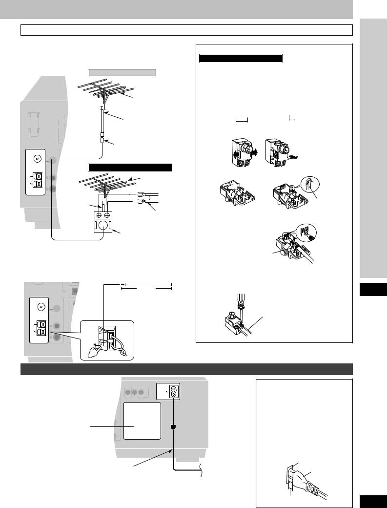
To connect an outdoor antenna
FM outdoor antenna
¡Disconnect the FM indoor antenna.
¡The antenna should be installed by a competent technician.
For the United Kingdom
|
FM outdoor antenna |
|
(not included) |
LOOP ANT |
75 W coaxial cable |
HOLDER |
(not included) |
|
|
|
Antenna plug (included) |
FM
ANT
75 Ω |
|
|
|
For Australia and New Zealand |
|
LOOP |
FM outdoor antenna |
|
(not included) |
||
EXT |
||
AM |
75 W |
|
ANT |
coaxial cable |
|
|
||
|
(not included) |
|
|
300 W feeder wire |
|
|
(not included) |
|
|
Antenna plug (included) |
AM outdoor antenna
¡Run a piece of vinyl wire horizontally across a window or other convenient location.
¡Leave the loop antenna connected.
¡Disconnect the antenna when the unit is not in use. Do not use the antenna during an electrical storm.
PHONO
FM
ANT
|
GND |
75 Ω |
|
LOOP |
L |
|
|
EXT |
|
AM |
R |
ANT |
|
5–12 m
Vinyl-covered wire
(not included)
How to use the antenna plug (included)
For Australia and New Zealand
Two types of wire are most commonly used for connection from the antenna: 300 W parallel feeder wire or 75 W coaxial cable. For best resistance to outside interference, the use of 75 W coaxial cable is suggested.
¡To connect a 75 Ω coaxial cable
q Remove a piece of the outer vinyl insulator.
 a
a 


20 mm |
10 mm |
w Carefully pull the tabs apart to remove the cover.
e Remove the lead wire and clamp it with the plastic bar.
 Lead wire
Plastic bar
rInstall the coaxial cable.
Clamp the cable conductor, and wind it on so that it doesn’t contact anything else.
Press down with pliers.
t Attach the cover.
¡To connect a 300 Ω feeder wire
Loosen the screws, connect the wires, and tighten the screws to secure the connection.
300 Ω feeder wire (not included)
Connections
Connecting the AC mains lead and other information
IN MONITOR
OUT
AC IN
VCR 1 TV
S-VIDEO
Cooling fan
The cooling fan operates at high power output levels only.
AC mains lead (included) |
|
To household mains |
|
|
|
|
socket |
|
|
|
|
|
|
Note |
|
(FOR THE UNITED KINGDOM ONLY) |
|
|
|
|
The included AC mains lead is for |
||
READ THE CAUTION FOR THE AC MAINS |
|
||
|
use with this unit only. |
||
LEAD ON PAGE 3 BEFORE CONNECTION. |
|
||
|
Do not use it with other equipment. |
||
AC mains lead
Connect this lead only after all other cables and cords are connected.
Insertion of Connector
Even when the connector is perfectly inserted, depending on the type of inlet used, the front part of the connector may jut out as shown in the drawing.
However there is no problem using the unit.
Appliance inlet |
|
Connector |
|
Approx. 6 mm |
13 |
|
RQT5518
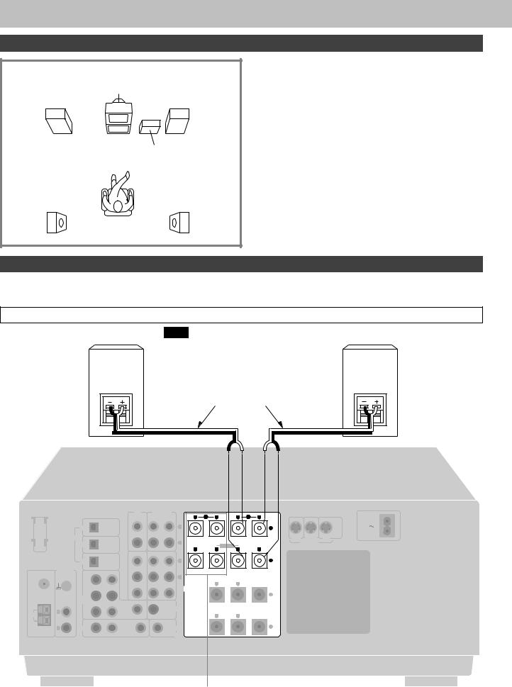
Speaker connections
Placement of speakers
Front speaker |
Center speaker |
Front speaker |
||
(left) |
(not included) |
(right) |
||
(not included) |
|
|
|
(not included) |
|
|
|
|
|
|
|
|
|
|
|
Subwoofer |
|
(not included) |
Surround speaker |
Surround speaker |
(left) |
(right) |
(not included) |
(not included) |
Front speakers
Place on the left and right of the TV at seated ear height so that there is good coherency between the picture and sound.
Center speaker
Place underneath or above the center of the TV. Aim the speaker at the seating area.
Surround speakers
Place on the side of or slightly behind the listening position, about one meter higher than ear level.
Subwoofer
The subwoofer can be placed in any position as long as it is at a reasonable distance from the TV.
Note that some experimentation can yield the smoothest low frequency performance. Placement near a corner can increase the apparent output level, but can result in unnatural bass.
Connecting speakers
Other connections are possible depending on your speaker system.
See your speaker system’s operating instructions for details.
Front speakers
Front speaker
(right)
(not included)
Note
If you connect speakers with an impedance
under 6 Ω, switch on “LOW IMP” (\ page 24).
Front speaker (left)
(not included)
Speaker cables (not included)
|
|
|
|
|
CD |
TAPE/MD |
|
L FRONT R |
|
|
|
|
|
||
|
|
|
|
|
|
REC |
PLAY |
R B |
A |
L |
IN |
IN |
MONITOR |
||
|
|
OPTICAL |
|
|
(OUT) |
(IN) |
|
|
|
|
|
||||
|
|
|
|
|
|
|
|
|
|
|
|
|
OUT |
||
|
|
|
|
|
|
|
|
|
|
|
|
|
|
|
|
LOOP ANT |
|
CD |
|
|
|
|
L |
|
|
|
|
|
+ |
|
AC IN |
HOLDER |
|
|
|
|
|
|
|
|
|
|
|
|
|
|
|
|
|
DIGITAL OPTICAL |
|
|
|
|
|
|
|
|
|
DVD |
VCR 1 |
TV |
|
|
|
DVD |
|
|
|
|
R |
|
LF BI-WIRE |
HF |
|
|
|
S-VIDEO |
|
|
|
|
|
|
|
|
|
|
|
|
|
|
|||
|
|
|
|
|
VCR 2 |
VCR 1 |
R |
L |
R |
|
L |
|
|
|
|
|
|
OPTICAL |
|
|
|
|
|
|
|
|
|
||||
|
|
|
|
|
|
|
|
|
|
|
|
|
|
||
|
|
TV |
|
|
|
|
L |
|
|
|
|
|
– |
|
|
|
PHONO |
FRONT L |
IN |
OUT |
IN |
|
|
|
|
|
|
|
|
||
FM |
|
|
|
|
|
|
|
|
|
|
|
||||
|
R |
|
|
R |
|
|
|
|
|
|
|
|
|||
ANT |
GND |
|
|
|
|
|
|
|
|
|
|
|
|
|
|
|
|
|
|
|
|
|
|
R SURROUND L |
|
CENTER |
|
|
|
||
75 Ω |
|
|
|
|
IN |
OUT |
IN |
|
|
|
|
|
|||
|
SUBWOOFER |
CENTER |
|
|
SPEAKERS |
|
|
|
|
|
|
|
|||
|
|
IN |
|
|
|
|
|
|
|
|
|
|
+ |
|
|
|
|
DVD/ |
|
|
|
|
|
|
|
|
|
|
|
|
|
|
|
|
|
|
|
|
|
|
|
|
|
|
|
|
|
|
|
DVD 6CH |
|
SURROUND |
|
|
|
|
|
|
|
|
|
|
|
|
|
SURROUND |
|
|
|
|
|
|
|
|
|
|
|
||
|
|
R |
|
L |
|
|
SUBWOOFER |
|
|
|
|
|
|
|
|
|
L |
|
|
|
|
|
|
|
|
|
|
|
|
|
|
LOOP |
|
|
|
IN |
|
OUT |
|
R |
L |
|
|
|
|
|
|
|
|
|
|
|
|
|
|
|
|
|
|
||||
EXT |
|
|
|
|
|
|
|
|
|
|
|
|
|
|
|
AM |
R |
TV |
|
|
|
|
TV |
|
|
|
|
|
– |
|
|
ANT |
|
R |
IN |
L |
IN |
|
MONITOR OUT |
|
|
|
|
|
|
|
|
|
|
|
|
|
|
|
|
|
|
|
|||||
|
|
|
|
“B” terminals |
|||
|
|
|
|
For connection to a second pair of speakers. |
|||
|
|
Speaker impedance: |
|
||||
|
|
|
|
|
|
||
|
|
A or B: 4-16 |
Ω |
|
Note |
|
|
14 |
|||||||
|
A and B: 8-16 |
Ω |
Use the A terminals to enjoy SURROUND, SFC and DVD 6CH INPUT. |
||||
|
|
|
|
|
|
|
|
RQT5518
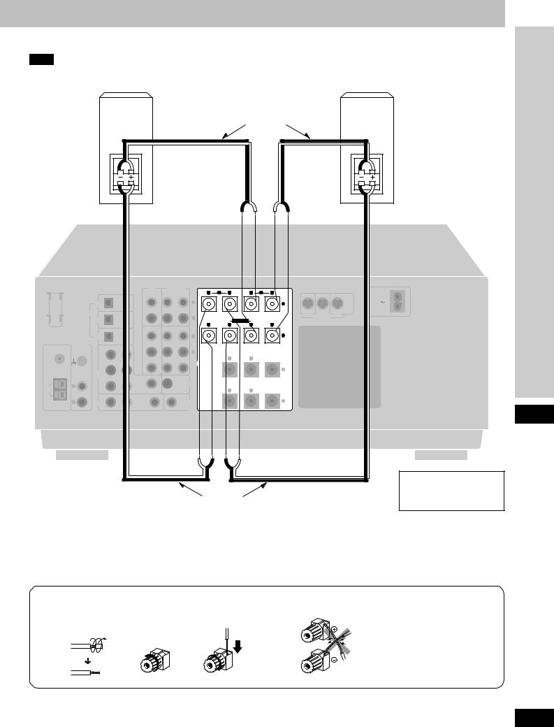
Bi-wiring connection
Note
When bi-wiring, use speakers designed for that purpose that have combined impedance of 6–16 Ω.
|
|
|
|
|
|
|
|
|
|
|
|
|
Speaker cables |
|
|
|
||
|
|
|
|
|
|
|
|
|
|
|
|
|
(not included) |
|
|
|
||
Front speaker |
|
|
|
|
|
|
|
|
|
|
|
|
|
|
|
|
|
|
(right) |
|
|
|
|
|
|
|
|
|
|
|
|
|
|
|
|
|
|
(not included) |
|
|
|
|
|
|
|
|
|
|
|
|
|
|
|
|
|
|
|
|
|
HF |
|
|
|
|
|
|
|
|
|
|
|
|
|
|
HF |
|
|
|
LF |
|
|
|
|
|
|
|
|
|
|
|
|
|
|
LF |
|
|
|
|
|
|
|
CD |
TAPE/MD |
|
|
L FRONT R |
|
|
|
|
|
||
|
|
|
|
|
|
|
|
REC |
PLAY |
R |
B |
A |
L |
IN |
IN |
MONITOR |
||
|
|
|
OPTICAL |
|
|
|
(OUT) |
(IN) |
|
|
|
|
|
|
||||
|
|
|
|
|
|
|
|
|
|
|
|
|
|
|
|
OUT |
||
|
|
|
|
|
|
|
|
|
|
|
|
|
|
|
|
|
|
|
LOOP ANT |
|
CD |
|
|
|
|
|
|
L |
|
|
|
|
|
+ |
|
|
AC IN |
HOLDER |
|
|
|
|
|
|
|
|
|
|
|
|
|
|
|
|
|
|
|
DIGITAL |
OPTICAL |
|
|
|
|
|
|
|
|
|
|
|
DVD |
VCR 1 |
TV |
||
|
|
DVD |
|
|
|
|
|
R |
|
|
LF |
BI-WIRE HF |
|
|
|
S-VIDEO |
|
|
|
|
|
|
|
|
|
|
|
|
|
|
|
|
|
||||
|
|
|
|
|
|
|
VCR 2 |
VCR 1 |
R |
|
L |
R |
|
L |
|
|
|
|
|
|
|
OPTICAL |
|
|
|
|
|
|
|
|
|
|
|
||||
|
|
TV |
|
|
|
|
|
|
L |
|
|
|
|
|
– |
|
|
|
|
PHONO |
|
|
FRONT |
|
IN |
OUT |
IN |
|
|
|
|
|
|
|
|
|
|
FM |
|
R |
L |
|
|
|
|
|
|
|
|
|
|
|
|
|||
|
|
|
|
R |
|
|
|
|
|
|
|
|
|
|||||
ANT |
GND |
|
|
|
|
|
|
|
|
|
|
|
|
|
|
|
|
|
|
|
|
|
|
|
|
|
|
|
|
R SURROUND L |
|
CENTER |
|
|
|
||
75 Ω |
|
|
|
|
|
|
IN |
OUT |
IN |
|
|
|
|
|
|
|||
|
|
SUBWOOFER |
CENTER |
|
|
SPEAKERS |
|
|
|
|
|
|
|
|
||||
|
|
|
IN |
|
|
|
|
|
|
|
|
|
|
|
+ |
|
|
|
|
|
DVD/ |
|
|
|
|
|
|
|
|
|
|
|
|
|
|
||
|
|
|
|
|
|
|
|
|
|
|
|
|
|
|
|
|
||
|
|
DVD 6CH |
|
SURROUND |
|
|
|
|
|
|
|
|
|
|
|
|
||
|
|
|
SURROUND |
|
|
|
|
|
|
|
|
|
|
|
|
|||
|
|
|
R |
|
|
L |
|
|
SUBWOOFER |
|
|
|
|
|
|
|
|
|
|
L |
|
|
|
|
|
|
|
|
|
|
|
|
|
|
|
|
|
LOOP |
|
|
|
|
|
IN |
|
OUT |
|
|
R |
L |
|
|
|
|
|
|
|
|
|
|
|
|
|
|
|
|
|
|
|
|
|
||||
EXT |
|
|
|
|
|
|
|
|
|
|
|
|
|
|
|
|
|
|
AM |
R |
TV |
|
|
|
|
|
|
TV |
|
|
|
|
|
– |
|
|
|
ANT |
|
|
R |
IN |
|
L |
IN |
|
MONITOR OUT |
|
|
|
|
|
|
|
|
|
|
|
|
|
|
|
|
|
|
|
|
|
|
|
|||||
Speaker cables (not included)
Front speaker (left)
(not included)
Speaker impedance:
BI-WIRE: 6-16 Ω
Connections
Connecting the cables
1 |
2 |
3 |
NO
15
RQT5518
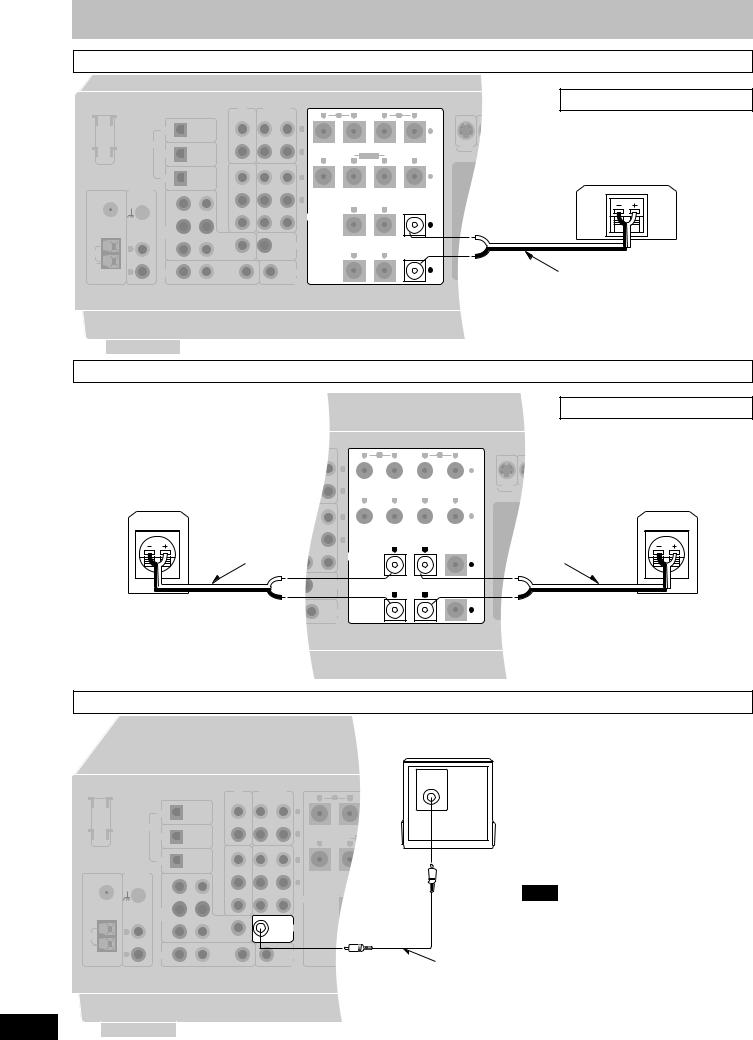
Speaker connections
Center speaker
|
|
|
|
|
CD |
TAPE/MD |
|
L FRONT |
|
|
|
|
|
|
|
|
|
|
REC |
PLAY |
R B |
R |
A |
L |
|
|
|
OPTICAL |
|
|
(OUT) |
(IN) |
|
|
|
|
|
|
LOOP ANT |
|
CD |
|
|
|
|
L |
|
|
|
|
|
HOLDER |
|
|
|
|
|
|
|
|
|
|
|
|
|
|
DIGITAL OPTICAL |
|
|
|
|
|
|
|
|
|
|
|
|
DVD |
|
|
|
|
R |
|
LF BI-WIRE |
HF |
|
|
|
|
|
|
|
|
|
|
|
|
|||
|
|
|
|
|
VCR 2 |
VCR 1 |
R |
L |
R |
|
L |
|
|
|
OPTICAL |
|
|
|
|
|
|
||||
|
|
TV |
|
|
|
|
L |
|
|
|
|
|
|
PHONO |
FRONT L |
IN |
OUT |
IN |
|
|
|
|
|
||
FM |
|
|
|
|
|
|
|
|
||||
|
R |
|
|
R |
|
|
|
|
|
|||
ANT |
GND |
|
|
|
|
|
|
|
|
|
|
|
|
|
|
|
|
|
|
|
R SURROUND L |
|
CENTER |
||
75 Ω |
|
|
|
|
IN |
OUT |
IN |
|
|
|||
|
|
|
|
|
|
|
|
|
||||
|
SUBWOOFER |
CENTER |
|
|
SPEAKERS |
|
|
|
|
|||
|
|
IN |
|
|
|
|
|
|
|
|
|
|
|
|
DVD/ |
|
|
|
|
|
|
|
|
|
|
|
|
DVD 6CH |
|
SURROUND |
|
|
|
|
|
|
|
|
|
|
SURROUND |
|
|
|
|
|
|
|
|
||
|
|
R |
|
L |
|
|
SUBWOOFER |
|
|
|
|
|
LOOP |
L |
|
|
|
IN |
|
OUT |
|
R |
L |
|
|
|
|
|
|
|
|
|
|
|
||||
EXT |
|
|
|
|
|
|
|
|
|
|
|
|
AM |
R |
TV |
|
|
|
|
TV |
|
|
|
|
|
ANT |
|
R |
IN |
L |
IN |
|
MONITOR OUT |
|
|
|
|
|
|
|
|
|
|
|
|
|
|||||
Speaker impedance: 6-16 Ω
Center speaker (not included)
Speaker cable (not included)
Surround speakers
Speaker impedance: 6-16 Ω
Surround speaker (right)
(not included)
Speaker cable 
(not included)
R B |
L FRONT |
R |
A |
|
L |
|
||||||||
|
|
|
|
|
|
|
|
|
|
|
|
|
+ |
|
|
|
|
|
|
|
|
|
|
|
|
|
|
|
|
|
|
LF |
|
|
|
|
HF |
|
|
|
|
|
||
|
|
|
|
|
|
|
|
|
|
|
|
|
||
|
|
|
BI-WIRE |
|
|
|
|
|
|
|
||||
|
|
|
|
|
|
|
|
|
|
|||||
R |
L |
|
|
R |
|
|
L |
|
||||||
|
|
|
|
|
|
|
|
|
|
|
|
|
– |
|
|
|
|
|
|
|
|
|
|
|
|
|
|
|
|
|
|
|
|
|
|
|
|
|
|
|
|
|
|
|
|
|
R SURROUND L |
|
CENTER |
|
|||||||||
+
Surround speaker (left)
(not included)
Speaker cable
(not included)
R L
–
Subwoofer
Active subwoofer (not included)
INPUT
|
|
|
|
|
CD |
TAPE/MD |
|
|
|
|
|
|
|
REC |
PLAY |
|
|
OPTICAL |
|
|
(OUT) |
(IN) |
|
LOOP ANT |
|
CD |
|
|
|
|
L |
HOLDER |
|
|
|
|
|
|
|
|
|
DIGITAL OPTICAL |
|
|
|
|
|
|
|
DVD |
|
|
|
|
R |
|
|
OPTICAL |
|
VCR 2 |
VCR 1 |
||
|
|
|
|
|
|
||
|
|
TV |
|
|
|
|
L |
|
PHONO |
FRONT L |
IN |
OUT |
IN |
||
FM |
|
|
|
||||
|
R |
|
|
R |
|||
ANT |
GND |
|
|
|
|
|
|
|
|
|
|
|
|
|
|
75 Ω |
|
SUBWOOFER |
CENTER |
IN |
OUT |
IN |
|
|
|
|
|
||||
|
|
IN |
|
|
|
|
|
|
|
DVD/ |
|
|
|
|
|
|
|
DVD 6CH |
|
SURROUND |
|
|
|
|
|
SURROUND |
|
|
SUBWOOFER |
||
|
|
R |
|
L |
|
|
|
|
|
|
|
|
|
|
|
LOOP |
L |
|
|
|
IN |
|
OUT |
|
|
|
|
|
|
|
|
EXT |
|
|
|
|
|
|
|
AM |
R |
TV |
|
|
|
|
TV |
ANT |
|
R |
IN |
L |
IN |
|
MONITOR OUT |
|
|
|
|||||
Monaural connection cable (not included)
16
Note
This receiver does not have an amplifier for the subwoofer.
To connect a passive subwoofer
¡Connect another amplifier and connect the subwoofer to it.
Or
¡Connect a passive subwoofer that has front speaker terminals
(See the operating instructions of the speaker system for details.)
RQT5518
Loading...