

Page 1

UR-4MD
DIGITAL VIDEO RECORDER
Instructions for use
ENGLISH
Page 2

2
Page 3

Contents
Thank you for choosing TEAC.
Read this manual carefully to get the best performance
from this unit. After reading this manual, keep it in a safe
place for future reference.
IMPORTANT SAFETY INSTRUCTIONS ..........................4
Intended use .............................................4
Introduction ................................................. 6
Before use ................................................... 6
What’s in the box .........................................6
Indication on the unit ..................................... 6
Setting up the unit ........................................6
Internal hard disk drive .................................... 7
Built-in battery ............................................ 7
Note about usable media ................................. 7
Note about the built-in fan ................................7
Front panel .................................................. 8
Rear panel ..................................................10
Preparations before turning the power on ..................12
Connecting the input cables .............................12
Connecting the output cables ...........................12
Connecting the audio input .............................12
Connecting the audio output ............................12
Connecting external switches ............................12
Connecting recording devices ...........................12
Connecting the power cord .............................12
Basic operations ............................................13
Turning the unit on ......................................13
Turning the unit off ......................................14
Energy-saving mode (Power save) ....................14
Standby (Shutdown) ..................................14
Basic menu operation. . . . . . . . . . . . . . . . . . . . . . . . . . . . . . . . . . . . 15
Formatting recording media .............................15
Recording ..................................................16
Determining where to save recorded data ...............16
To record to a USB drive ..............................16
To record to a network ................................16
Making external switch settings (video) ..................16
Recording video .........................................16
Taking photos ...........................................17
Inputting patient information ............................18
Inputting patient information with a keyboard ........18
Canceling the input of patient information ............18
Inputting patient information with a card/barcode ....19
Selecting how information is shown on an
external monitor .........................................19
Exiting recording mode ..................................19
Precautions when removing USB recording devices ...19
Playing back recordings ....................................21
Playing the newest video/photo .........................21
Playback operations .....................................21
Playing and pausing ..................................21
Stopping .............................................21
Changing playback speed ............................22
Jumping to an index ..................................22
Moving to the next recorded file ......................22
Moving to the next folder .............................23
Audio during playback ...................................23
Showing and playing back files in a list from the
most recent folder .......................................23
Searching for files by condition and playing them back ..24
Searching by ID .......................................24
Searching by name ...................................24
Searching by date ....................................25
Changing the device used for searching (playback) ...25
Managing recorded files ....................................26
Saving already recorded photos/videos on an
external device ..........................................26
Editing information for existing folders ...................28
Deleting data for existing folders .........................29
Folder structure used for recorded videos/photos ........30
Folder structure .......................................30
Viewing recorded videos/photos on a computer
(using HTML file on media) ............................31
List of recorded folders ................................31
List of videos/photos in folder .........................32
Settings ....................................................33
General settings .........................................33
Video IN ..............................................33
Audio IN ..............................................33
Video OUT ............................................33
Record To. . . . . . . . . . . . . . . . . . . . . . . . . . . . . . . . . . . . . . . . . . . . . 33
Playback From ........................................34
Clock .................................................34
Language .............................................34
Photo Options ...........................................34
Quality ................................................34
Format ...............................................34
Video Options ...........................................35
Quality ................................................35
Auto Index ............................................35
Ext Switch Trigger. . . . . . . . . . . . . . . . . . . . . . . . . . . . . . . . . . . . . 35
Advanced-1 .............................................35
Patient Info. Entry .....................................35
Auto File Division .....................................36
Format Recording Device .............................36
OSD ..................................................36
Copy to (from iHDD) ..................................36
Advanced-2 .............................................37
Erase iHDD (Keep) ....................................37
Storage Device Info.. . . . . . . . . . . . . . . . . . . . . . . . . . . . . . . . . . . 37
S.M.A.R.T. information ................................37
Beep ..................................................38
Updating the firmware ................................38
Network Options ........................................39
Mode Select ..........................................39
IP Address ............................................41
Current IP Address ....................................41
Optional accessories ........................................42
TEAC/TASCAM RC-10 remote control ....................42
TEAC/TASCAM RC-3F remote control ....................42
Maintenance ...............................................43
Recommended inspections ..............................43
Cleaning the unit ........................................43
Troubleshooting .........................................43
Specifications ...............................................44
Limits for electromagnetic compatibility (EMC) .............46
Software license information. . . . . . . . . . . . . . . . . . . . . . . . . . . . . . . . 50
GPL ......................................................51
LGPL Version 2 ...........................................52
LPGL Version 2.1 .........................................54
3
Page 4

IMPORTANT SAFETY INSTRUCTIONS
CAUTION: TO REDUCE THE RISK OF ELECTRIC SHOCK, DO NOT
REMOVE COVER (OR BACK). NO USER-SERVICEABLE PARTS
INSIDE. REFER SERVICING TO QUALIFIED SERVICE PERSONNEL.
The lightning flash with arrowhead symbol, within an
equilateral triangle, is intended to alert the user to the
M
V
WARNING: TO PREVENT FIRE OR SHOCK
HAZARD, DO NOT EXPOSE THIS APPLIANCE
TO RAIN OR MOISTURE.
1) Read these instructions.
2) Keep these instructions.
3) Heed all warnings.
4) Follow all instructions.
5) Explosion hazard: Do not use the apparatus in the presence of
6) Do not use this apparatus near liquids.
7) Do not install near any heat sources such as radiators, heat regis-
8) This apparatus conforms to Protection Class !. It is equipped
presence of uninsulated “dangerous voltage” within the
product’s enclosure that may be of sufficient magnitude
to constitute a risk of electric shock to persons.
The exclamation point within an equilateral triangle is
intended to alert the user to the presence of important
operating and maintenance (servicing) instructions in
the literature accompanying the appliance.
flammable anesthetics or explosive gases.
o Do not expose this apparatus to drips or splashes.
o Do not place any objects filled with liquids on the apparatus.
o Clean only with a slightly dampened cloth.
ters, or other apparatus that produce heat.
o Do not block any ventilation openings. Install in accordance
with the manufacturer’s instructions.
o Do not install this apparatus in a confined space such as a book
case or similar unit.
with a three-pole mains power connector and a power cord that
has a 3-prong grounding plug. The cord of such a product must
be plugged into an AC outlet that has a protective grounding
connection.
o Do not defeat the safety purpose of the grounding-type plug. If
the provided plug does not fit into your outlet, consult an electrician for replacement of the obsolete outlet.
o The apparatus should be located close enough to the AC outlet
so that you can easily grasp the power cord plug at any time.
The power plug is used as the disconnect device, the disconnect device shall remain readily operable.
o Protect the power cord from being pinched particularly at
plugs, convenience receptacles, and the point where they exit
from the apparatus.
o Lay the power cord in such a way that nobody can step on it,
drive over it or stumble over it.
o Do not use the apparatus with a damaged power cord.
o Unplug this apparatus during lightning storms or when unused
for long periods of time.
9) The UR-4MD has a replaceable lithium battery. There is danger of
explosion if a battery is replaced with an incorrect type of battery. When changing the battery is necessary, contact the retailer
where you purchased the unit or a contact on the back cover of
this manual and request replacement.
10) Only use attachments/accessories specified by the manufacturer.
11) Use only with the cart, stand, tripod, bracket, or
table specified by the manufacturer, or sold with
the apparatus. When a cart is used, use caution
when moving the cart/apparatus combination to
avoid injury from tip-over.
12) Refer all servicing to qualified service personnel. Servicing is
required when the apparatus has been damaged in any way, such
as liquid has been spilled or objects have fallen into the apparatus,
the apparatus has been exposed to rain or moisture, does not
operate normally, or has been dropped. Do not use the apparatus
until it has been repaired.
13) Do not modify the apparatus in any way. Use of controls or adjustments or performance of procedures other than those specified
herein may result in hazardous radiation exposure.
14) Caution when using earphones or headphones with the apparatus: Excessive sound pressure (volume) from earphones or headphones can cause hearing loss.
Intended use
This product is a video recorder for use in medical facilities. It is
intended to be used for backup recording of examinations and operations in combination with surgical microscopes, endoscope cameras,
medical displays and similar devices.
o This product is not intended to be used for diagnoses.
o Use this product only in accordance with these instructions for use.
Disposal method:
Follow local regulations for proper disposal.
Environmental information:
The UR-4MD draws nominal non-operating power from the AC outlet
when switched off on the front panel while its main power switch is
still in the on position ( | ).
4
Page 5
Federal Communications Commission (FCC) statement
Pb, Hg, Cd
IMPORTANT SAFETY INSTRUCTIONS
Declaration of Conformity
Model Number: UR-4MD
Trade Name: TEAC
Responsible party: TEAC AMERICA, INC.
Address: 1834 Gage Road, Montebello, California,90640, U.S.A.
Telephone number: 1-323-726-0303
This device complies with Part 15 of the FCC Rules. Operation is subject to the following two conditions: (1) this device may not cause
harmful interference, and (2) this device must accept any interference received, including interference that may cause undesired
operation.
Important notice
Changes or modifications to the equipment not expressly approved
by TEAC CORPORATION for compliance could void the user's authority to operate this equipment.
NOTE:
This equipment has been tested and found to comply with the limits for a Class B digital device, pursuant to Part 15 of the FCC Rules.
These limits are designed to provide reasonable protection against
harmful interference in a residential installation. This equipment
generates, uses and can radiate radio frequency energy and, if not
installed and used in accordance with the instructions, may cause
harmful interference to radio communications. However, there is no
guarantee that interference will not occur in a particular installation.
If this equipment does cause harmful interference to radio or television reception, which can be determined by turning the equipment
off and on, the user is encouraged to try to correct the interference
by one or more of the following measures:
1) Reorient or relocate the receiving antenna.
2) Increase the separation between the equipment and receiver.
3) Connect the equipment into an outlet on a circuit different from
that to which the receiver is connected.
4) Consult the dealer or an experienced radio/TV technician for help.
For Canada
Industry Canada Compliance Statement:
This Class B digital apparatus complies with Canadian ICES-003.
Cet appareil numérique de la classe B est conforme à la norme NMB-003 du Canada.
For Europe
Disposal of electrical and electronic equipment
1) All electrical and electronic equipment should be disposed of
separately from the municipal waste stream via collection facilities designated by the government or local authorities.
2) By disposing of electrical and electronic equipment correctly,
you will help save valuable resources and prevent any potential
negative effects on human health and the environment.
3) Improper disposal of waste electrical and electronic equipment
can have serious effects on the environment and human health
because of the presence of hazardous substances in the
equipment.
4) The Waste Electrical and Electronic Equipment (WEEE)
symbol, which shows a wheeled bin that has been
crossed out, indicates that electrical and electronic
equipment must be collected and disposed of separately from household waste.
5) Return and collection systems are available to end users. For
more detailed information about the disposal of old electrical and electronic equipment, please contact your city office,
waste disposal service or the shop where you purchased the
equipment.
Disposal of batteries and/or accumulators
1) Waste batteries and/or accumulators should be disposed of
separately from the municipal waste stream via collection facilities designated by the government or local authorities.
2) By disposing of waste batteries and/or accumulators correctly,
you will help save valuable resources and prevent any potential
negative effects on human health and the environment.
3) Improper disposal of waste batteries and/or accumulators can
have serious effects on the environment and human health
because of the presence of hazardous substances in them.
4) The WEEE symbol, which shows a wheeled bin that has
been crossed out, indicates that batteries and/or accumulators must be collected and disposed of separately
from household waste.
If a battery or accumulator contains more than the specified values of lead (Pb), mercury (Hg), and/or cadmium (Cd) as defined
in the Battery Directive (2006/66/EC), then the chemical symbols
for those elements will be indicated beneath the WEEE symbol.
5) Return and collection systems are available to end users. For
more detailed information about the disposal of waste batteries
and/or accumulators, please contact your city office, waste disposal service or the shop where you purchased them.
DECLARATION OF CONFORMITY
We, TEAC EUROPE GmbH., Bahnstrasse 12, 65205 Wiesbaden-Erbenheim, Germany declare in own responsibility, the TEAC
product described in this manual is in compliance with the European Directive for medical devices 93/42/EEC.
5
Page 6
Introduction
Before use
Copyright and disclaimers
Information is given about products in this manual only for the
purpose of example and does not indicate any guarantees against
infringements of third-party intellectual property rights and other
rights related to them. TEAC Corporation will bear no responsibility
for infringements on third-party intellectual property rights or their
occurrence because of the use of these products.
This product is licensed under the AVC patent portfolio license for
the personal use of a consumer or other uses in which it does not
receive remuneration to (I) encode video in compliance with the
AVC standard (“AVC video”) and/or (II) decode AVC video that was
encoded by a consumer engaged in a personal activity and/or was
obtained from a video provider licensed to provide AVC video. No
license is granted or shall be implied for any other use. Additional
information may be obtained from MPEG LA, L.L.C.
See http://www.mpegla.com
Other company names and product names in this document are
the trademarks or registered trademarks of their respective owners.
Information about open source copyrights and licensing is contained in the section “Software license information” at the end of
this document.
Features
o Automatic sensing of resolution and input connection
makes connecting other equipment easy
o Record buttons for video and photo allow quick start-
ing for easy operation
o Recording and playback of videos and photos for
extended periods is possible
o Photos can be taken while recording video
o External contact switches can be used to control
recording
o Simultaneous recording to both the internal hard disk
and a USB drive provides high confidence data saving
o Supports high-definition formats up to WUXGA
o Built-in liquid-crystal display (LCD) allows input
images to be checked and status to be displayed
o Contents can be transferred over a network
o S.M.A.R.T. status of internal hard disk allows checking
for malfunction
o Short-term retention of power prevents data loss
when power is interrupted
o Light and compact design
What’s in the box
Check to be sure the box includes all the supplied accessories shown below. Please contact the retailer where
you purchased the unit or a contact on the back cover
of this manual if any of these items are missing or have
been damaged during transportation.
Power cord × 1
Instructions for use (this document) × 1
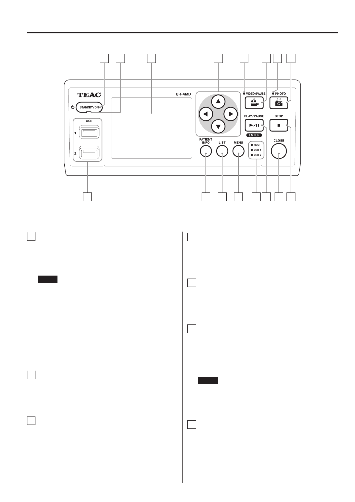
Indication on the unit
Front panel
Indication Function
Use this button to turn the unit on/
off.
Rear panel
Indication Function
Use this connector to supply power
to the unit. Connect the included
power cord here.
This is a potential equalization connector. Connect a potential equalization cable with a connector that is
compliant with DIN 42801 here.
Use this connector to connect to a
network.
Use this connector to input video
signals.
Use this connector to output video
signals.
Setting up the unit
Before using the UR-4MD, read and follow all safety
instructions given in section “IMPORTANT SAFETY
INSTRUCTIONS” on page 4.
Set up the unit in a location that meets the following requirements in order to ensure safe and proper
operation.
o Environmental conditions:
• Temperature: 5–40 °C
• Humidity: 5–80 %RH (no condensation)
• Maximum wet bulb temperature: 29 °C
• Electromagnetic environment: See “Limits for electromagnetic compatibility (EMC)” on page 46.
o Place the unit with its rubber feet down and install on
a level surface. Avoid vibrations.
6
Page 7

Before use
o Avoid use in the following types of places because
doing so could result in malfunction or other trouble:
• Near equipment that generates high-frequency
waves.
• Where strong magnetic force or static electricity is
present.
o Depending on the television broadcast frequency,
uneven colors might appear on televisions that are
used near this unit when its power is on. This is not
a malfunction of either this device or the television.
If this should happen, use the unit further from the
affected device.
o Before packing the unit for relocation or transporta-
tion, for example, disconnect all cables and other
devices. Not doing so could damage the connectors.
Internal hard disk drive
This unit has a built-in hard disk drive (HDD). This HDD is
easily affected by impact forces, vibrations and changes
in the environment, including the temperature, and this
could affect video that is being recorded.
Please observe the following precautions.
• Do not subject the unit to vibrations or impacts.
• Place and use the unit on a level surface.
• Do not turn the unit off while its hard disk is being
accessed.
Built-in battery
This unit has a battery to run the internal clock. If this battery dies, the correct time cannot be retained, and this
will affect the time information of recorded images. We
recommend changing the battery every five years before
it dies. When changing the battery is necessary, contact
the retailer where you purchased the unit or a contact on
the back cover of this manual and request replacement.
Note about usable media
You can connect USB flash drives and USB hard drives
to this unit. Format the media with this unit before
recording.
Note about the built-in fan
The fan built into this unit has a limited lifespan. If it
breaks, contact the retailer where you purchased the
unit or a contact on the back cover of this manual and
request repair.
IMPORTANT NOTICE
Long-term storage of recorded contents on the builtin HDD cannot be guaranteed. Moreover, as space
becomes necessary, the oldest recordings will be
erased automatically. We recommend that you use
a LAN or USB drive to transfer important video and
photo data for storage on a computer or DVD, for
example.
IMPORTANT NOTICE
Hard disk drives eventually fail. Depending on use
conditions, problems might start occurring in a few
years. If recording or playback becomes impossible,
contact the retailer where you purchased the unit or a
contact on the back cover of this manual and request
repair.
7
Page 8
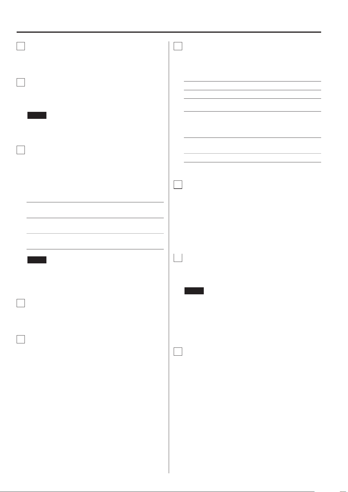
Front panel
A B GC D E F
OP
H
I J K L MN
A
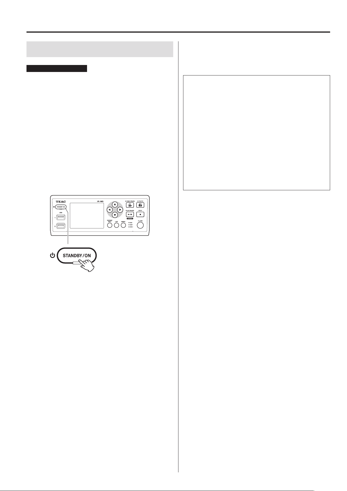
STANDBY/ON button
Press to turn the unit on. The LCD display lights.
When the power is on, press it to put the unit into
energy-saving mode.
NOTE
o The unit will only turn on if the main power switch
on the back of the unit is set to On ( | ).
o Press and hold for at least 1 second to shut the unit
down.
o Press and hold for about 4 seconds to force the
unit to shut down.
See “Turning the unit off” on page 14 for details.
B
STANDBY LED
Solid green: On
Solid amber: Standby
D
5, b, g, t buttons
Use these to change and select menu items and to
view recorded photos and videos.
E
VIDEO LED
Lit: Video being recorded
Blinking: Video recording paused
F
VIDEO/PAUSE button
Press to start video recording.
Press this button during video recording to pause
recording.
Press it again to resume recording.
NOTE
When video recording is paused, an index is created
at that point.
C
LCD display
This shows input images (previews), playback images,
status information and setting menus.
8
G
PHOTO LED
This lights when photos are being recorded.
Page 9
Front panel
H
PHOTO button
Use to record photos.
I
USB ports (USB 1/USB 2)
Connect USB flash drives and hard disk drives to
these.
NOTE
Do not connect USB hubs.
J
PATIENT INFO button
Press to show patient information when, for example,
you want to input or check it.
Press and hold for 1 second to toggle between the
following options of how information is shown on an
external monitor:
Information is shown (“OSD1” appears briefly on
the external monitor)
Information is not shown (“OSD2” appears briefly on
the external monitor)
Only status icon is shown (“OSD3” appears briefly on
the external monitor)
M
Status LEDs
These show the access status of the internal HDD and
drives connected to USB 1 and USB 2.
Internal HDD
Solid green: Normal
Unlit: Error
USB 1/2
Solid green: Device connection recognized
In this state, the device can also
be securely removed
Amber: Writing or formatting (or device
being connected)
Unlit: No device
N
PLAY/PAUSE button
ENTER button
Press to play a recorded file.
Press during video playback to pause playback.
When making a menu setting, press to confirm the
selected item.
NOTE
If “Patient Info. Entry” is set to “Off”, patient information
will not be shown.
K
LIST button
Press to show the list of already recorded folders.
L
MENU button
Press to open the menu in order to make unit
settings.
O
CLOSE button
Press to end recording, playback, menu operations or
searching and close the current patient folder.
NOTE
Press this button to close any open files and folders.
Wait until the USB status LED lights green before you
disconnect a USB drive. Not doing so could damage
recorded data.
P
STOP button
Press during video recording to stop recording. Press
during video playback to stop playback.
9
Page 10
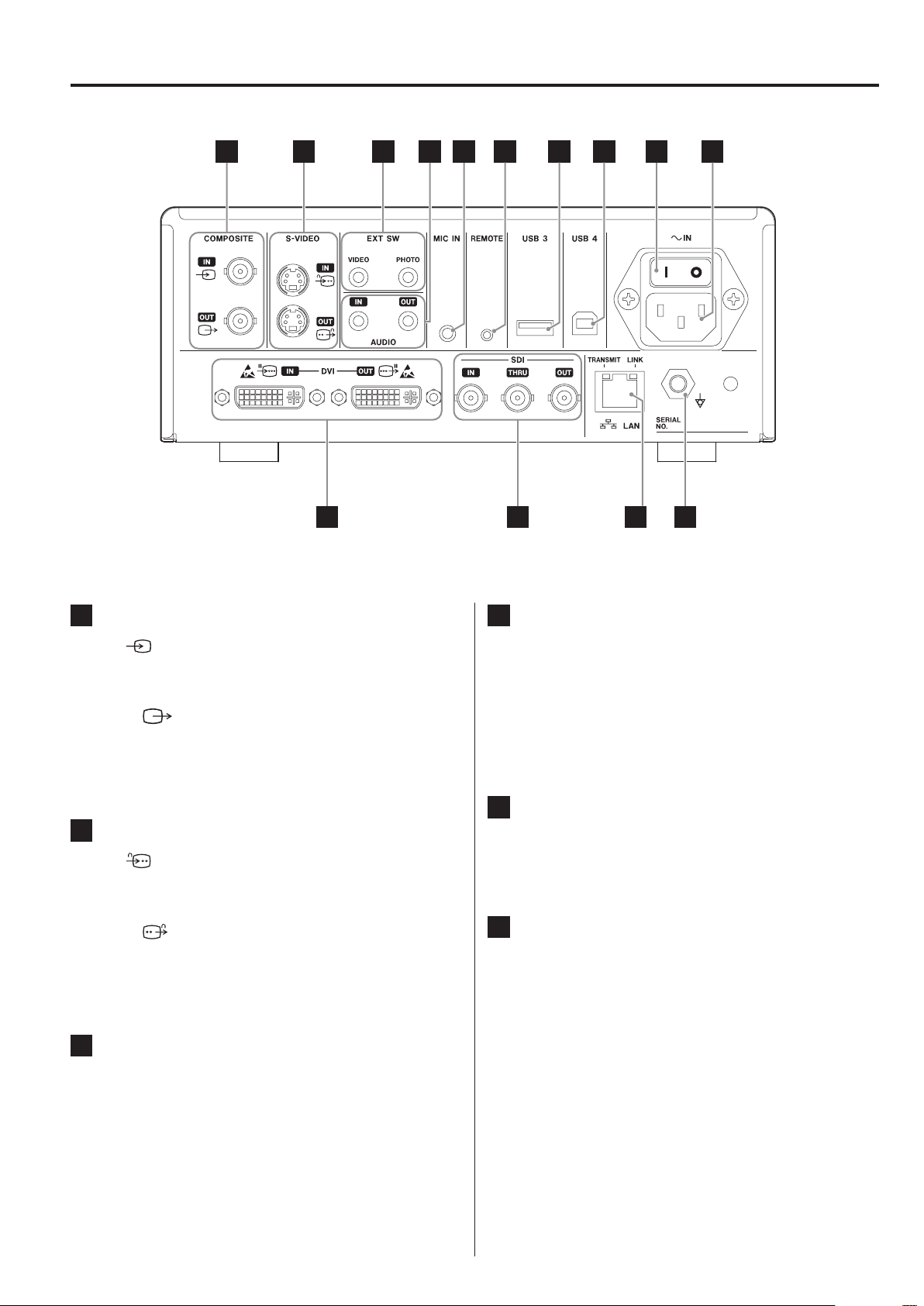
Rear panel
A B C D E F G H JI
NK L M
A
COMPOSITE input/output connectors
IN ( )
Input a Composite Video (NTSC/PAL) signal here.
(BNC connector)
OUT ( )
This outputs a Composite Video (NTSC/PAL) signal.
(BNC connector)
B
S-VIDEO input/output connectors
IN ( )
Input an S-Video (NTSC/PAL) signal here.
(S connector)
OUT ( )
This outputs an S-VIDEO (NTSC/PAL) signal.
(S connector)
C
External switch input connectors
D
AUDIO input/output connectors
IN
Input an audio signal here. (3.5-mm stereo mini jack)
OUT
This outputs an audio signal. (3.5-mm stereo mini
jack)
E
MIC IN (input) connector
Connect a microphone here to input an audio signal.
(3.5-mm mini jack)
F
REMOTE connector
Connect a TEAC/TASCAM RC-10 wired remote controller or TEAC/TASCAM RC-3F foot switch (sold separately) to use for controlling this unit. (2.5-mm mini
jack)
(EXTSW)
Connect external VIDEO and PHOTO switches here.
(3.5-mm stereo mini jacks)
10
Page 11
Rear panel
G
USB port (USB 3)
You can connect a USB keyboard, a card reader or a
barcode reader to input patient information here.
(USB 2.0 Type A)
Use a card reader or a barcode reader that has keyboard interface specifications.
For details, please contact TEAC or a TEAC distributor.
NOTE
USB hubs cannot be connected here.
H
USB port (USB 4)
Use to access data on this unit from an external
device (when set to USB Mass Storage) or to control
this unit with commands from an external device
(when not set to USB Mass Storage).
To control this unit with commands, you must create
a communication program. For details, please contact
TEAC or one of the TEAC distributors.
(USB 2.0 Type B).
L
SDI connectors
IN
Input an SDI video signal here. (BNC connector)
THRU
This passes through input SDI video signals. (BNC
connector)
OUT
This outputs an SDI video signal. (BNC connector)
M
LAN connector
Use to connect the unit to a network. Follow the
instructions provided by the network administrator
regarding connections and settings.
(10BASE-T/100BASE-TX/1000BASE-T (RJ-45))
LINK LED
This lights when a link pulse is detected.
TRANSMIT LED
This blinks during transmission.
NOTE
USB hubs cannot be connected here.
I
Main power switch
Use to enable/disable power supply to the unit. This
switch needs to be in the On position ( | ) in order for
the front-panel STANDBY/ON button to operate.
J
Power cord connector (~IN)
Connect the included power cord here.
Always connect the power cord to a grounded power
outlet.
K
DVI input/output connectors
IN ( )
Input a DVI (DVI-D) video signal here.
OUT ( )
This outputs a DVI (DVI-D) video signal.
N
Potential equalization connector ( )
Use to connect a potential equalization cable with a
connector that complies with DIN 42801.
When using this in combination with other medical
equipment, connect the devices using dedicated
cables.
IMPORTANT NOTICE
Connectors that display this mark are susceptible to internal damage from static electricity.
Be careful not to touch the connector contact
points with bare hands.
11
Page 12
Preparations before turning the power on
Connecting the input cables
This unit has S-VIDEO and COMPOSITE VIDEO standard
video input connectors and DVI and SDI high definition
video input connectors.
Connect input cables to the connectors that you will use.
Connecting the output cables
This unit has S-VIDEO and COMPOSITE VIDEO standard
video output connectors and DVI and SDI high definition
video output connectors.
In connection example 1 below, input images cannot be
seen on the monitor when this unit is off.
If connected as shown in example 2, input images can be
seen on the monitor even when this unit is off.
Connection example 1
Image device This unit Monitor
Connecting recording devices
Recording to a USB drive
Connect the USB drive to the USB 1 or USB 2 port on the
front of the unit. When the USB drive is on, the corresponding LED lights green.
To disconnect it, press the CLOSE button. Disconnect
it after the corresponding USB LED stops blinking
(becomes lit green again).
For details about settings, see “Determining where to
save recorded data” on page 16 and “Record To” on
page 33.
Recording to a network
Use a cable to connect to the communication network.
For details about settings, see “Network Options” on page
39.
Connecting the power cord
Connection example 2
Image device This unit Monitor
Different signal input to this unit
Connecting the audio input
This unit has an audio input connector. Connect the
audio input connector as necessary.
For SDI audio, this can be used together with the SDI
video input connector.
For details, see the “Audio IN” item (page 33).
Connecting the audio output
This unit has an audio output connector. Connect the
audio output connector as necessary.
For SDI audio, this can be used together with the SDI
video output connector.
V
CAUTION
Only connect this unit to a mains voltage of AC 100–
240 V ±10 % (50/60 Hz). Any other power supply
could cause fire or electric shock.
Always use isolation transformers in order to prevent
electric shocks.
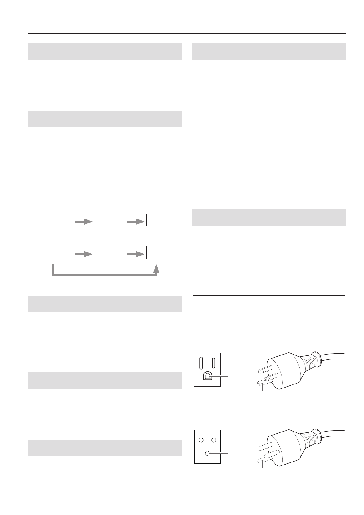
The power cord has a three-pronged plug. In order to
assure safe use, do not connect it to a two-pronged
(ungrounded) outlet.
For USA:
Grounding
Outlet Grounding plug
For Europe:
Connecting external switches
This unit has external switch connectors (EXT SW).
Connect the external switch connectors as necessary
(see page 16).
12
Grounding
Outlet Grounding plug
Page 13
Basic operations
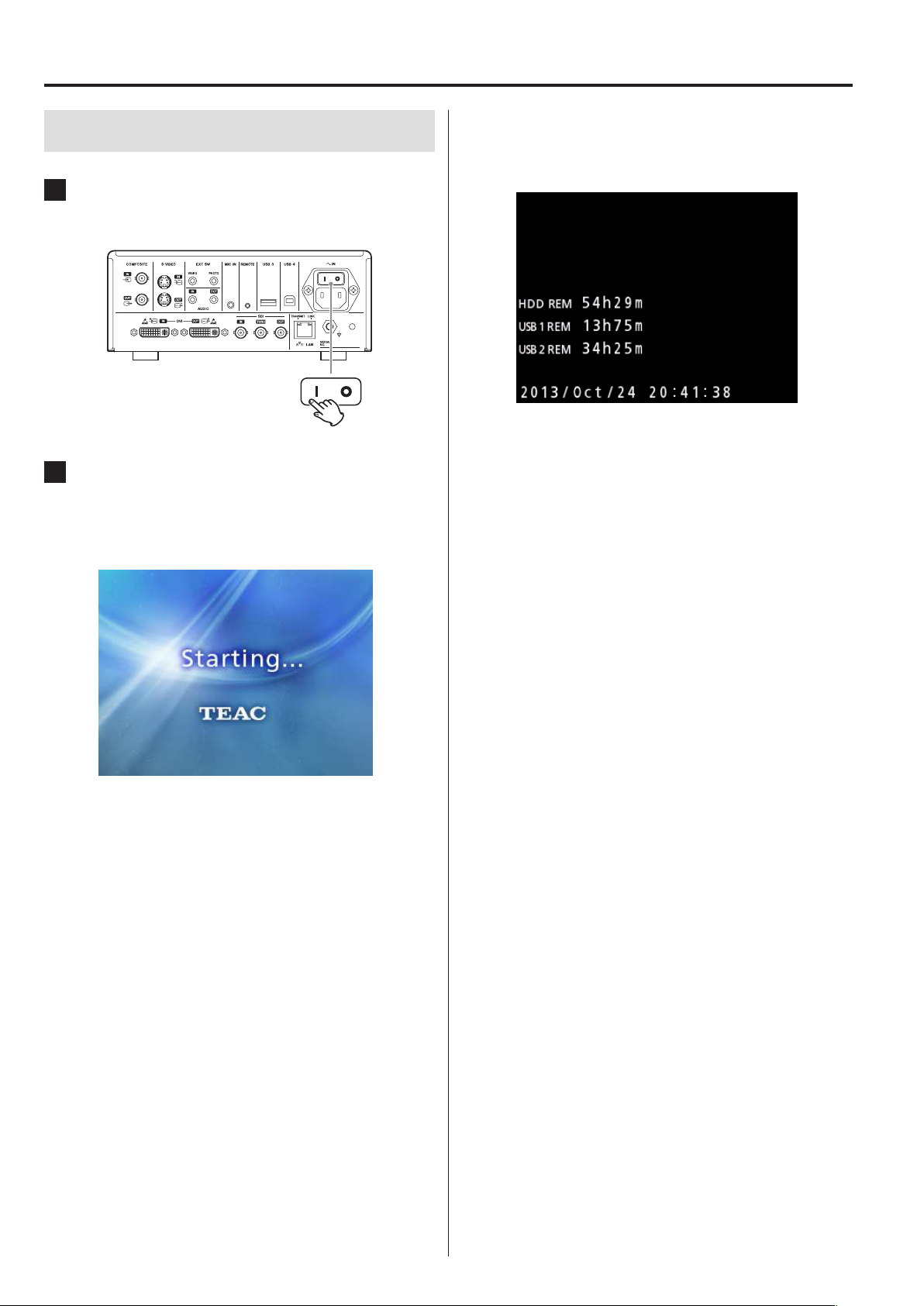
Turning the unit on
1 Set the main power switch on the back
of the unit to the on ( | ) position.
2 Press the STANDBY/ON button on the
front of the unit.
The LCD display on the front of the unit lights, and
“Starting…” appears.
When the front panel LCD shows text about various status items, the unit is ready for the next user
operation.
o If video is being input, that video will appear in the
background.
After the unit starts, the input video is shown. If there
is no input, a black background will be shown.
13
Page 14
Basic operations
Turning the unit off
IMPORTANT NOTICE
Before turning the unit off (standby or energy-saving
mode):
o Stop recording
o End access to all media (make sure the USB status LED
for connected memory devices lights green)
Shutdown procedures will be conducted if the power is
suddenly interrupted, but data preservation cannot be
guaranteed. In particular, turning the power off while any
media is being accessed could damage data, making it
unusable.
o To put the unit into energy-saving mode:
Press the STANDBY/ON button briey.
Standby (Shutdown)
This turns the unit off. Restarting the unit will take about
30 seconds.
When the unit will not be used for a long
time
If this unit will not be used for a long time, follow the
procedures below to switch the unit off.
1. Press and hold the STANDBY/ON button on the
front panel to put the unit into standby.
2. Set the main power switch on the rear panel to
the Off position (˜).
o The STANDBY LED stays lit for a few minutes after
the main power has been turned off because of
the short-term power retention function for use
during power outages. When this reserve power is
depleted, the STANDBY LED will extinguish.
o To put the unit into standby:
Press the STANDBY/ON button for about
one second.
Energy-saving mode (Power save)
In this mode, the unit stays ready while conserving
energy. This is useful if you want to be able to use the
unit sometime soon without waiting.
o In energy-saving mode, the fan will continue to turn.
14
Page 15
Basic operations
Basic menu operation
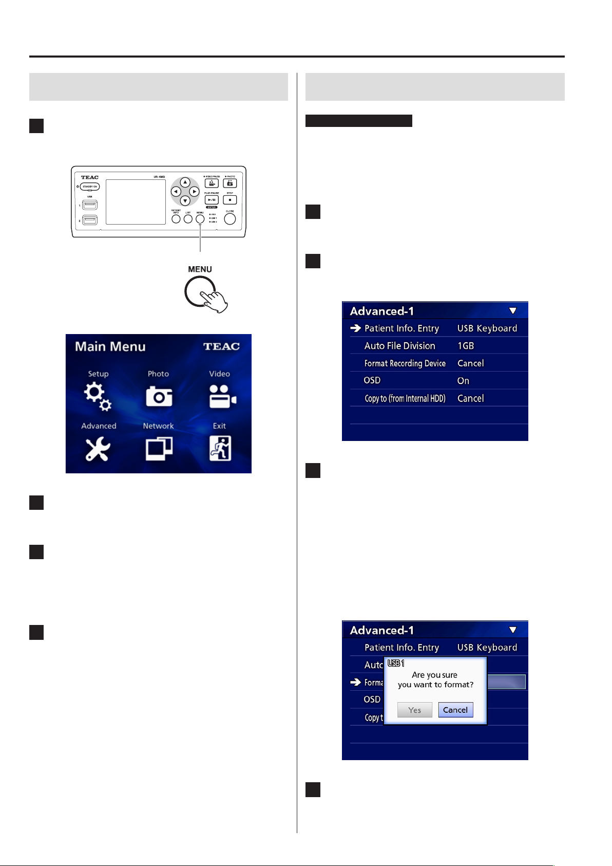
1 Press the MENU button to open the main
menu.
Formatting recording media
IMPORTANT NOTICE
Be aware that doing this will erase all the data on the
selected medium.
If the internal HDD is selected, the data on the hard disk
in this unit will be erased.
1 Press the MENU button to open the Main
Menu.
2 Select “Advanced” e “Format Recording
Device”.
3 Select the medium you wish to format
and press the ENTER button.
2 Use the 5, b, g and t buttons to
change the selection.
3 Press the ENTER button to open the
selected menu.
o To return to the previous screen, press the MENU
button.
USB1
Format the medium connected to USB port 1.
USB2
Format the medium connected to USB port 2.
HDD
Format the internal hard disk.
4 To close the Main Menu, press the CLOSE
button, or press the ENTER button when
“Exit” is selected.
4 Select “Yes” to start formatting.
15
Page 16
Recording
Determining where to save recorded data
Before starting recording, set where recording data will
be saved.
o The unit always records to the internal HDD.
o Depending on the setting, the unit is able to record
simultaneously to the internal HDD, to USB 1, USB 2
and to the network.
To record to a USB drive
1 Press the MENU button.
2 Select “Setup” e “Record To”.
3 Select one of the following settings.
USB1 + USB2
Record the same data to both USB 1 and USB 2.
USB1
Record to only USB 1.
USB2
Record to only USB 2.
o Recording will be made from the image at the time a
device is connected to the corresponding USB port.
Recorded images from before the connection was
made will not be transferred to the connected device.
o Do not connect or disconnect USB drives while
recording. Doing so could result in the loss of not
only the data being recorded, but also data that has
already been recorded. Furthermore, doing this could
cause other malfunction.
Making external switch settings (video)
You can connect external switches to the EXT SW connectors on the rear panel and use them to control this
unit.
1 Press the MENU button.
2 Select “Video” e “Ext. Switch Trigger”.
3 Set the desired operation.
For details, see “Ext Switch Trigger” in“Video Options”
on page 35.
NOTE
There are no external switch settings for still images.
Recording video
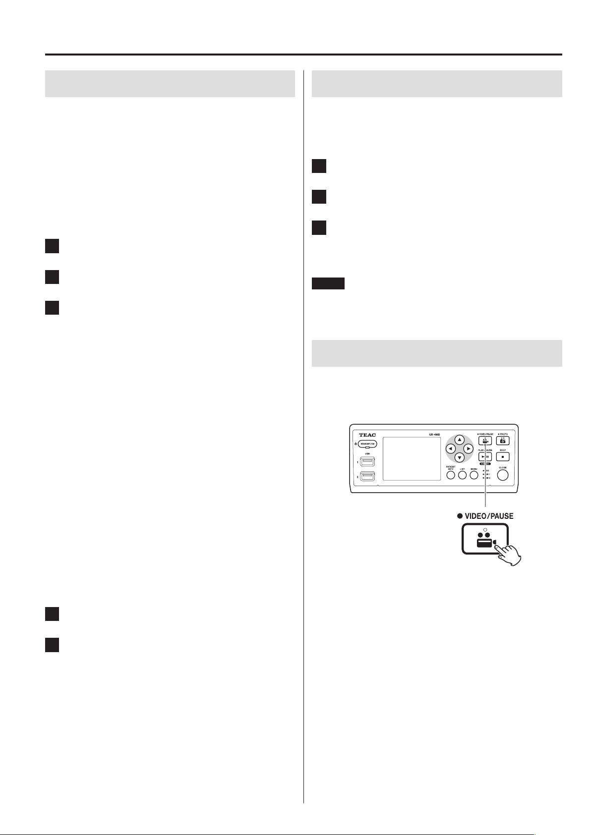
o Press the VIDEO/PAUSE button on the
front panel to start recording video.
To record to a network
1 Press the MENU button.
2 Select “Network” e “Mode Select” and
set the desired network mode.
CIFS client
This unit will be a CIFS client, and recordings will be
saved to the network share configured in the CIFS client settings.
FTP client
This unit will be an FTP client, and recordings will be
saved to the FTP server.
16
o Press the VIDEO/PAUSE button again to
pause recording.
o Press the STOP button to stop video
recording.
o If recording is started before patient information is
input, the video will have no patient information. If
patient information is necessary, refer to “Inputting
patient information” on page 18, and input patient
information before you start recording video.
o To disable on-screen information while recording
video, press and hold the PATIENT INFO button. Or set
“OSD” accordingly (see “OSD” on page 36).
Page 17
Recording
During video recording, the following will occur.
o If video is being input, that video will appear in the
background.
o During video recording, the VIDEO LED above the
VIDEO/PAUSE button will light amber.
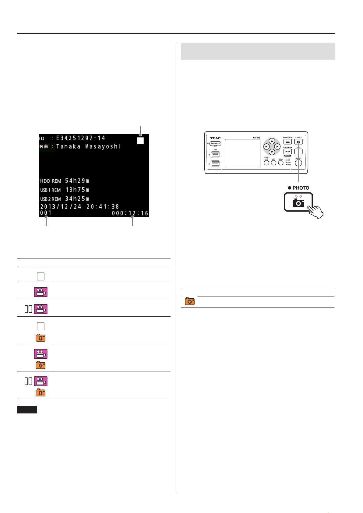
o A status icon will appear at the top right of the display.
o While capturing video recording, you can press the
PHOTO button to take a photo.
Status icon
Taking photos
o Press the PHOTO button on the front of
the unit to take a photo.
The PHOTO LED above the PHOTO button lights
amber briefly.
A camera icon briefly appears at the top right of the
display.
Number of recordings
(999 maximum)
Icons that appear during recording
Icon Explanation
Stopped
Video being recorded
Paused during video recording
Photo taken while video recording stopped
Photo taken while recording video
Photo taken while video recording paused
Recording time
o If a photo is taken before patient information is input,
the photo will have no patient information. If patient
information is necessary, refer to “Inputting patient
information” on page 18, and input patient information before you take a photo.
Icon that appears when taking a photo
Icon Explanation
Photo being taken
NOTE
When recording for a long time, the file will automatically
be divided. The division size depends on the setting (see
page 36).
Even if a file has been divided, the recording can be
played back on this unit without interruption.
17
Page 18

Recording
Inputting patient information
A USB keyboard, card reader or barcode reader is necessary to input patient information.
o Refer to “Patient Info. Entry” on page 35 and set up
the input device being used.
Inputting patient information with a keyboard
You can use a USB keyboard connected to the USB 3 port
on the back of the unit to input patient information.
Use the USB keyboard to input the ID, name, sex and
birth date of the patient.
1 Press the PATIENT INFO button.
Hospital, Procedure, Modality and Operation Room are immediately retained internally. Erase item information that is not
needed.
3 Press the ENTER button to conrm.
Buttons and corresponding USB keyboard keys
Operation Button USB keyboard
New patient PATIENT INFO F10
Move to field
above
Move to field
below
Move cursor left
Move cursor right
Confirm and
enable recording
Close the screen CLOSE
Delete character at
cursor
Delete character to
left of cursor
Character input — Character code
5 2 (up-arrow)
b x (down-arrow)
g s (left-arrow)
t w (right-arrow)
ENTER ENTER
F1
ESC
PATIENT INFO
— DEL
— Backspace
2 Use the keyboard to input the information.
NOTE
o If you do not press the front panel ENTER button
or keyboard ENTER key, the input value will not be
confirmed.
o Only English letters and numerals can be input.
o Use a keyboard according to the “Language” setting.
Canceling the input of patient information
On the patient information input screen, press the CLOSE
or PATIENT INFO button.
18
Page 19

Recording
Inputting patient information with a card/ barcode
You can connect a card reader or a barcode reader to the
USB port 3 on the rear panel of the unit to input patient
information.
1 Press the PATIENT INFO button.
2 Read the card/barcode.
3 Press the ENTER button to conrm and
enable video recording.
Exiting recording mode
Press the CLOSE button to clear the patient information
and exit recording mode.
Videos and photos from before pressing the CLOSE button will be stored in the same folder. The maximum number of images, including both still and video images, in
one folder is 999. If this number is reached and you want
to record further, press the CLOSE button to end recording once. When recording is next started, a new folder
will be created.
Precautions when removing USB record-
NOTE
o If you do not press the front panel ENTER button, the
input value will not be confirmed.
o Only English letters and numerals can be input.
o Characters other than English letters and numerals
cannot be shown properly.
Selecting how information is shown on an external monitor
Press and hold the PATIENT INFO button for 1 second to
toggle between the following options of how information is shown on an external monitor:
Information is shown (“OSD1” appears briefly on the
external monitor)
Information is not shown (“OSD2” appears briefly on the
external monitor)
Only status icon is shown (“OSD3” appears briefly on the
external monitor)
ing devices
After pressing the CLOSE button to stop recording video
or photos, do not immediately disconnect the USB
device because the unit continues writing to the USB
device for some time.
Disconnecting a USB device when writing could cause
some of the recorded images and management files to
be damaged, resulting in the loss of image data. Follow
these procedures when disconnecting USB devices:
1 Press the CLOSE button to stop record-
ing and wait until all the status LEDs
light green.
Depending on the recording time, several minutes
might pass before they all light green.
2 After conrming that all LEDs are lit
green, press the LIST button and conrm
that the recorded images are at the very
top of the list.
3 Conrm that the playback device shown
at the bottom left corner of the display is
a USB device (USB1 or USB2).
19
Page 20

Recording
4 Conrm that you can play back recorded
images.
5 Press the CLOSE button to stop
playback.
6 After the playback icon disappears from
the display, disconnect the USB device.
20
Page 21

Playing back recordings
Playing the newest video/photo
Press the front panel PLAY/PAUSE button to play back the
most recently recorded data.
Icons that appear during playback
Icon Explanation
Ordinary video playback
Playback paused
1, 2, 3, 4 or 5 appears depending on the
video playback speed
Photo being shown
Playback operations
Playing and pausing
Press the PLAY/PAUSE button.
o During ordinary video playback, this pauses playback.
o At all other times, this starts ordinary playback (normal
1× speed).
o When viewing a photo, this does nothing.
Stopping
During playback, press the CLOSE or STOP button to stop
playback.
Status icon
Recording start
date and time
Playback time/image recording time
Playback image number/total number of images in folder
IMPORTANT NOTICE
The newest video/photo can only be played immediately
after starting up or immediately after recording.
Opening the list or starting playback will change the
playback folder.
21
Page 22

Playing back recordings
Changing playback speed
During video playback, press the t button to increase
the playback speed one level at a time.
Press the g button to decrease the playback speed one
level.
NOTE
o This unit does not have a “rewind” function.
o When playing back at high speed, the video could
become irregular. If this happens, restart normal playback and try again.
Moving to the next recorded file
When viewing photos or when video playback ends,
press the 5 button to move to the next file.
Press the b button to move to the previous file.
Jumping to an index
When viewing video, press and hold the t button to
jump to the next index and play the video from there.
If there are no more indexes until the end of the video,
this will jump to the end of the video and pause playback
instead.
Press and hold the g button to jump to the previous
index and play the video from there.
If there are no more indexes until the beginning of the
video, this will jump to the beginning of the video and
play the video from there.
22
Press at least 2
seconds
Page 23

Playing back recordings
Moving to the next folder
During playback or when playback is paused, press the
5 button for at least two seconds to move to the next
folder.
Press at least 2
seconds
Press the b button for two or more seconds to move to
the previous folder.
Audio during playback
Audio is played only during ordinary playback.
NOTE
Audio is not played during high-speed playback.
Showing and playing back files in a list from the most recent folder
Press the LIST button or the USB keyboard F3 key to show
the recording data in the most recently dated folder.
Press at least
2 seconds
Detected device
Current folder number/total number of folders
23
Page 24

Playing back recordings
Searching for files by condition and
playing them back
NOTE
If “Patient Info. Entry” is set to “Off”, the search function
cannot be used.
Searching by ID
1 Press the PATIENT INFO button.
2 Move the cursor to the ID eld.
3 Use a USB keyboard to input the ID.
4 Press the LIST button or the USB key-
board F3 key to start searching.
Searching by name
1 Press the PATIENT INFO button.
2 Move the cursor to the NAME eld.
3 Use a USB keyboard to input the name.
4 Press the LIST button or the USB key-
board F3 key to start searching.
24
Page 25

Playing back recordings
Searching by date
1 Press the PATIENT INFO button.
2 Move the cursor to the DATE eld.
3 Use a USB keyboard to input the date.
4 Press the LIST button or the USB key-
board F3 key to start searching.
Changing the device used for searching (playback)
On the search result screen, press the g or t button,
or the USB keyboard s or w key to change devices in
the following order.
Internal HDD USB 1 USB 2
Buttons and corresponding USB keyboard keys
Operation Button USB keyboard
New patient PATIENT INFO F10
Move to field above
Move to field below
Move cursor left
Move cursor right
Confirm and record ENTER ENTER
Close the screen CLOSE
Delete character at
cursor
Delete character to
left of cursor
Character input — Character code
Start search LIST F3
5 2 (up-arrow)
b x (down-arrow)
g s (left-arrow)
t w (right-arrow)
F1
ESC
PATIENT INFO
— DEL
— Backspace
25
Page 26

Managing recorded files
Saving already recorded photos/videos on an external device
You can use this unit to copy data recorded on it to an
external device. Use the “Copy to (from iHDD)” function
on the “Advanced-1” screen (page 36).
Copying to USB 1 or USB 2
1 Press the MENU button.
2 Select “Advanced”.
3 Select “Copy to (from iHDD)”.
4 Select “USB1” or “USB2”.
5 Select the order to copy folders.
Copying to an FTP server
1 Press the MENU button.
2 Select “Advanced”.
3 Select “Copy to (from iHDD)”.
4 Select “Network (FTP)”.
5 Select the order to copy folders.
NOTE
o All videos and photos in that folder will be copied.
Selecting individual files for copying is not possible.
o Confirm that the copy destination has enough open
space.
If the internal HDD contains a large amount of data,
copying could require several hours.
We recommend that you copy when you do not need
to use the unit for extended periods.
NOTE
For details about FTP server settings, see “FTP Server” in
“Mode Select” on page 39.
Copying to a CIFS server
1 Press the MENU button.
2 Select “Advanced”.
3 Select “Copy to (from iHDD)”.
4 Select “Network (CIFS)”.
5 Select the order to copy folders.
26
NOTE
For details about CIFS server settings, see “CIFS Server” in
“Mode Select” on page 39.
Page 27

Managing recorded files
Copying a specified folder
1 Press the LIST button to open the list.
o If the internal HDD list is not shown, use the d
and e buttons to set the searched (playback)
device to “HDD”.
2 Use the 3 and c buttons to select the
folder you want to copy, and press the
MENU button.
4 Use the 3 and c buttons to select the
copy destination, and press the ENTER
button.
Devices to which copying is currently possible are
shown as copy destinations.
5 When a conrmation dialog appears,
press the d button to select “Yes”, and
then press the ENTER button.
A pop-up menu appears.
3 Use the 3 and c buttons to select
“Copy”, and press the ENTER button.
This opens the “Destination” pop-up menu.
o Copying cannot be started if the copy destination
does not have enough open space.
o You can cancel copying while in progress by press-
ing the ENTER button.
27
Page 28

Managing recorded files
6 When the “Copy completed!” message
appears, press the ENTER button to
return to the list.
Editing information for existing folders
1 Press the LIST button to open the list.
2 Use the 3 and c buttons to select the
folder with information you want to edit,
and press the MENU button.
A pop-up menu appears.
28
3 Use the 3 and c buttons to select “Edit”,
and press the ENTER button.
Page 29

Managing recorded files
The PATIENT INFORMATION screen for the folder
opens.
4 Change the folder information, and
press the ENTER button.
A confirmation dialog appears.
Deleting data for existing folders
1 Press the LIST button to open the list.
2 Use the 3 and c buttons to select the
folder to delete, and press the MENU
button.
A pop-up menu appears.
5 Select “Yes” and press the ENTER button
to save the edited information.
IMPORTANT NOTICE
When being used as USB Mass Storage or on a network,
editing folder information might not be possible. In
this case, set the network mode to “Off” (see “Network
Options” on page 39).
3 Use the 3 and c buttons to select
“Delete”, and press the ENTER button.
29
Page 30

Managing recorded files
A confirmation dialog appears.
4 Select “Yes” and press the ENTER button.
A confirmation dialog appears again.
Folder structure used for recorded videos/photos
A folder is created for each patient with information
input. The folders are named in the following format
using the year, month, day, hour, minute, second and ID.
yymmddhhmmss_ID
NOTE
If the ID has a character that cannot be used in the file
name, that character will be replaced with a hash symbol
(#).
Folder information is updated when recording is completed (when the CLOSE button is pushed to end the
recording session).
Folder structure
5 If you are sure that deletion is okay,
select “Yes” and press the ENTER button.
The selected folder data will be deleted.
IMPORTANT NOTICE
o Deleted data cannot be restored. Be careful when
using this function.
o When being used as USB Mass Storage or on a net-
work, deleting folder information might not be pos-
sible. In this case, set the network mode to “Off” (see
“Network Options” on page 39).
Root directory
PatientList.html (html file)
20131216154525_000012345 (patient management folder)
video_files (video storage folder)
000001.mov (video file)
000002.mov (video file)
000004.mov (video file)
000005.mov (divided video file, part 1)
000005-002.mov (divided video file, part 2)
000007.mov
photo_files (photo storage folder)
000003.jpg (photo file (numbered in order taken))
000006.jpg (photo file)
Files.html (List of videos/photos in folder)
20131216181554_0000112255 (patient management folder)
video_files (video storage folder)
30
Page 31

Managing recorded files
Viewing recorded videos/photos on a computer (using HTML file on media)
Recorded videos/photos and information about folders can be viewed using an internet browser on a computer. Open
the file “PatientList.html” for this purpose.
List of recorded folders
The unit creates an HTML list (PatientList.html) of the folders recorded on the internal HDD.
In addition, when copying data to an external USB drive, an HTML list (PatientList.html) of the folders is created on that
device.
No: Folder number on media
They are shown in the order copied.
Date: Recording date
ID: Patient ID (link to list of videos/photos in folder)
Name: Patient name (link to list of videos/photos in folder)
D.O.B.: Patient date of birth (stored character string shown as is)
Sex: Patient sex
Num of image: Number of videos/photos in the folder (link to list of videos/photos in folder)
31
Page 32

Managing recorded files
List of videos/photos in folder
Click a patient ID or Name in the Folder List to show the list as follows.
No: Number of video/photo in folder, divided videos are shown with a hyphen (–)
File: File name (link)
Size: Actual file size
Length: Recording time or “Photo”, divided videos are shown with a hyphen (–)
32
Page 33

Settings
General settings
Move the cursor to the item to be set, and press the
ENTER button to enable the item to be changed.
Video IN
Automatic video input switching is supported
When video signal input is detected, the video input will
automatically be switched. When multiple video signals
are input, the unit will switch to the video input with the
highest priority.
The input video signal is detected in the following order.
SDI DVI S-VIDEO COMPOSITE
Set the video input with the highest priority.
For example, if “Video IN” is set to “DVI”, the priority will be
as follows.
DVI w SDI w S-VIDEO w COMPOSITE
o If the video input is COMPOSITE, it will not switch to
S-VIDEO.
o If the video input is S-VIDEO, it will not switch to
COMPOSITE.
o Moreover, video input will not switch during
recording.
Manual video input switching
When not recording or playing back, press and hold the
5 or b button to search for a different input connector
that has a video signal and switch to it. If no video signal
input is found, nothing will change.
Audio IN
Set the audio input with the highest priority.
SDI
AUDIO
MIC
Automatic audio input switching
When audio input is detected together with video input,
it will automatically be switched.
The audio input signal is detected in the following order.
SDI AUDIO MIC
For example, if the setting is AUDIO, the priority will be as
follows.
AUDIO w SDI w MIC
o Presence of a digital signal is detected for SDI, and
connected plugs are detected for the AUDIO and MIC
input jacks.
o Moreover, audio input will not switch during
recording.
o SDI audio can only be selected when the video input
is SDI.
o SDI audio will only function when using SDI video
input. Moreover, if the video input is an SDI signal with
embedded audio data, SDI audio will be set and cannot be changed (AUDIO and MIC cannot be used).
Video OUT
This sets the resolution of the output video signal when
there is no input video signal.
NTSC: Output from COMPOSITE and S-VIDEO OUT
connectors
PAL: Output from COMPOSITE and S-VIDEO OUT
connectors
1024x768: Output from DVI OUT connector
1920x1080: Output from DVI and SDI OUT connectors
o During playback, the set video resolution will be out-
put if it is different from the playback image even if
there is an input video signal.
Record To
Use this to set the USB connector to which further
recording devices are connected.
USB1 + USB2
USB1
USB2
o The unit always records to the internal HDD.
33
Page 34

Settings
o When set to USB1 + USB2, the same video/photo is
recorded to both. However, it is possible to use only
one USB drive with this setting.
Playback From
This sets the playback device.
USB1
USB2
Internal HDD
o If the set device is not available during playback, the
unit will check the connections in the order above
and search for a device.
Clock
This shows the current date and time.
The selected element (cursor location) appears
highlighted.
g, t:
5, b:
ENTER: Confirm the set date and time.
MENU: Cancel the date and time change.
Note
This unit’s built-in clock will not always stay accurate. We
recommend checking and adjusting the time setting on
a regular basis.
Move the cursor to the previous/next element.
Increase or decrease the element’s value.
Photo Options
Quality
Use to set the quality of photos taken.
HQ: High quality
SQ: Standard quality
EQ: Economy quality (small file size)
Format
JPEG: JPEG compression
JPEG (info on): JPEG compression
The following folder information is
embedded at the top of photos:
Date, ID, Name, Date of birth, Sex,
Hospital, Physician
DICOM (.dcm): DICOM file format (photo is JPEG format)
Language
Set the language used by the menus.
English
日本語
Français
Deutsch
Italiano
Español
한국어
中文
Português
Türkçe
IMPORTANT NOTICE
Uncompressed DICOM photos are not supported. Only
JPEG-compressed photos are supported.
34
Page 35

Settings
Video Options
Quality
Use to set the quality of video recorded.
HQ: High quality
SQ: Standard quality
EQ: Economy quality (small file size)
Auto Index
Set how indexes are added to videos during recording.
Off: Indexes are not added.
1 min: An index is added every minute.
5 min: An index is added every 5 minutes.
10 min: An index is added every 10 minutes.
20 Even
Per File:
After a video is recorded, the recording is
divided into 20 equal intervals, and indexes
are added.
Ext Switch Trigger
Advanced-1
Patient Info. Entry
Select the device to use for inputting patient information.
(This setting is only applied to patient information input.)
Off: Patient information will not be input.
USB Keyboard: Enables use of a USB keyboard for
patient information input.
Card/Barcode
Reader:
o Enhanced standard US layout keyboards are supported.
o Connect USB devices for patient information input to
the USB 3 port on the back of the unit.
When using magnetic cards/barcodes, set the range of
the characters to be read.
Enables use of a USB card/barcode
reader for patient information input.
When this setting is used, the following character range setting screen
will appear. Make settings for each
range of information.
Use to set the operation of external switches (EXT SW).
Push to Switch: Press to alternately start and pause
recording.
Hold to Record: Record while pressing.
35
Page 36

Settings
Range settings are from the position of the first character
(Start) to the position of the last character (End). If only
one character is used, the Start and End values are the
same.
ID: Set the character range used for the ID
Name: Set the character range used for the name
D.O.B.: Set the character range used for the date
of birth
Sex: Set the character range used for the sex
Show All
Info:
On this screen, all the data input by the
card/barcode reader is shown.
OSD
Set how information is shown on an external monitor
(OSD: on-screen display of patient information, remaining
capacity, time, etc.).
ON: Information is shown
OFF: Information is not shown
ICON: Only status icon is shown
You can also press and hold the PATIENT INFO button
to instantly toggle between the available options (see
“PATIENT INFO button” on page 9).
Copy to (from iHDD)
Use to copy recorded videos/photos from the internal
HDD to a different location (see page 26). Select the
copy destination device:
Cancel
USB1
USB2
Network (FTP)
Network (CIFS)
Auto File Division
Set the file size for automatic file division used when
recording video.
4 GB
1 GB
o Division is necessary due to file system limitations.
When using FTP transmission, smaller files are more
efficient.
o Depending on the video quality setting and the reso-
lution of the input video signal, the actual file division
size could become smaller than this setting.
Format Recording Device
Use this to format (initialize) the recording device (media).
Cancel
USB1
USB2
iHDD
After selecting the device, the following options are
shown in the line below.
Selecting an option will start copying.
From Older Folder: All data will be copied starting with
the oldest folder.
From Newer Folder: All data will be copied starting with
the newest folder.
IMPORTANT NOTICE
Formatting a device will erase all recorded data on it. Be
aware that this cannot be undone.
36
Page 37

Settings
Advanced-2
Erase iHDD (Keep)
Set how data is erased from the internal HDD. Data will
be erased according to this setting when the unit is
started.
Off: Do not erase. Recording will become
impossible when the HDD becomes
full.
Keep 200 GB: Folders will be erased from oldest first
so that about 200 GB of data remain.
Keep 100 GB: Folders will be erased from oldest first
so that about 100 GB of data remain.
Keep 50 GB: Folders will be erased from oldest first
so that about 50 GB of data remain.
Keep Last 24
Hours:
Keep Last 7 Days: Folders that are more than 7 days old
Folders that are more than 24 hours
old (from recording start time) are
erased.
(from recording start time) are erased.
iHDD Information: This shows information about the
internal HDD.
Capacity: This shows the total capacity.
Free Space: This shows the amount of free space.
Used Space: This shows the amount of space
already used.
iHDD S.M.A.R.T.: This shows S.M.A.R.T. information for
the internal HDD.
USB 1 S.M.A.R.T.: This shows S.M.A.R.T. information for
the device connected to USB 1.
USB 2 S.M.A.R.T.: This shows S.M.A.R.T. information for
the device connected to USB 2.
S.M.A.R.T. information
Storage Device Info.
This shows various information about the selected storage device.
This shows the “Current”, “Worst” and “Threshold” values
for each item.
01 Read Error Rate
02 Throughput Performance
05 Reallocated Sectors Count
07 Seek Error Rate
0A Spin Retry Count
C4 Reallocation Event Count
C5 Current Pending Sector Count
C6 Uncorrectable Sector Count
C8 Write Error Rate
DF Load/Unload Retry Count
37
Page 38

Settings
Beep
Use to turn the built-in beeping sound on/off.
On: Beep will sound.
Off: Beep will not sound.
o The beep will sound when, for example, buttons are
used, recording starts and warnings occur.
Updating the firmware
Follow these procedures to update this unit’s firmware.
Follow the procedures exactly. Failure to do so could
cause the unit to malfunction.
IMPORTANT NOTICE
o Before updating, back up recorded data as necessary.
After updating, the unit might not be able to play
earlier files. In addition, you should format the builtin hard drive after updating. (See “Format Recording
Device” on page 36.)
o Do not interrupt the power or remove a USB storage
device while updating. Doing so could cause the unit
to malfunction.
7 Press the MENU button.
8 Select “Advanced”.
9 Scroll down until the “Advanced-2”
screen appears.
10 Select “Firmware Update” and press
ENTER.
Cancel: Do not update.
Execute: Update the firmware.
11 Select “Execute” and press ENTER.
A confirmation dialog appears.
In the example illustrated below, the unit will be
updated from firmware version 1.00 to 1.02.
1 Format a USB ash drive with this unit.
See “Formatting recording media” on page 15.
2 Copy the rmware update le from the
computer to the root folder on the USB
ash drive.
12 Select “Yes” and press ENTER to start the
3 Press the STANDBY/ON button for one
second to shut the unit down.
update.
The following screen will appear.
4 Disconnect all cables from the LAN,
USB 3, USB 4 and video (SDI, DVI,
COMPOSITE, S-VIDEO) connectors on the
back of the unit.
5 Press the STANDBY/ON button to turn
the unit on.
IMPORTANT NOTICE
After turning the unit on, do not use record or playback functions before conducting the update.
o Updating can take a few minutes.
o When updating completes, the unit will automati-
cally restart. Wait until the unit restarts.
6 Connect the USB ash drive prepared for
the update to the unit’s USB port 1.
38
13 Reconnect the cables as necessary.
o Contact the retailer where you purchased the unit for
information about firmware updates.
Page 39

Settings
Network Options
Mode Select
Use to set the network mode.
Off: Disable network functions
FTP Client: Files will automatically be transmitted to the
set FTP server.*
CIFS Client: Files will automatically be transmitted to the
set CIFS server.*
CIFS Server: This unit becomes a CIFS server and its files
can be read from CIFS clients.
As a server, the unit is read-only.*
Reading is not possible during recording.
USB Mass
Storage:
Use this unit as a USB mass storage device,
allowing files to be read from a USB Host.
As a server, the unit is read-only.
Connect the USB host to the USB 4 port on
the back of the unit.
Reading is not possible during recording.
The external command control function
cannot be used at the same time. With this
setting, the USB Mass Storage function will
be used for operation. When not set to “USB
Mass Storage”, the external command control function will be used for operation.
Restarting the device is necessary when
switching to the “USB Mass Storage” setting
or switching from the “USB Mass Storage”
setting to another setting.
Depending on the selected setting, one of the following
screens for making detailed settings will appear.
Use a USB keyboard for input. (Connect it to the USB 3
port on the back of the unit.)
IMPORTANT NOTICE
o Operation on an unreliable network could cause loss
of data.
o A DNS server, for example, is necessary for name reso-
lution of the computer and unit IP addresses in the
setting of each mode.
FTP Client Mode
FTP Server: Use a USB keyboard to input the server
name.
User Name: Use a USB keyboard to input the user
name.
Password: Use a USB keyboard to input the
password.
Setting example:
FTP Server: 192.168.0.101
User Name: dvr
Password: abcde
*These options have screens for making detailed settings.
IMPORTANT NOTICE
o When using multiple recorders, recording data could
be lost if the recording destination is set to the same
location on the same server. Do not use the same
location setting.
o “User Name” and “Password” are required.
Corresponding user settings must also be made on
the server.
39
Page 40

Settings
CIFS Server Mode
Model Name
(or Machine
Name):
User Name: Use a USB keyboard to input the user name.
Password: Use a USB keyboard to input the password.
User name and password set here can be used for readonly access to this device from the network.
Setting example:
Model Name (or Machine Name): video_recoder
User Name: dvr
Password: abcde
Use a USB keyboard to input the model
name.
CIFS Client Mode
Path: Use a USB keyboard to input the network
path.
User Name: Use a USB keyboard to input the user name.
Password: Use a USB keyboard to input the password.
Setting example:
Path (host name or IP/share): 192.168.0.101/dvr_mount
User Name: dvr
Password: abcde
o The user/password set here must exist on the com-
puter where the share exists, and the user must have
access privileges for this share.
IMPORTANT NOTICE
When using multiple recorders, recording data could be
lost if the recording destination is set to the same location on the same server. Do not use the same location
setting.
40
Page 41

Settings
IP Address
Use this to set the unit’s network address.
Automatic
(DHCP):
Manual: Input the following network address
IP Address: Use a USB keyboard to set the IP
Subnet Mask: Use a USB keyboard to set the
Default
Gateway:
DNS Server1: Use a USB keyboard to set DNS
DNS Server2: Use a USB keyboard to set DNS
WINS Server: Use a USB keyboard to set the
NOTE
If the IP address setting is changed, the new setting will
be applied after the unit is restarted.
Use a DHCP server to automatically acquire
network settings. Select “Current IP Address”
on the “Network Options” screen to show
the acquired network address.
information.
address.
subnet mask.
Use a USB keyboard to set the
default gateway.
server 1.
server 2.
WINS server.
Current IP Address
This shows the currently set IP address.
41
Page 42

Optional accessories
By connecting one of the following remote controls to the REMOTE connector on the back of the UR-4MD, you can use
it to control the unit. The remote buttons/pedals and the unit functions that they control are as follows.
See the Owner’s Manual of each remote control for other information about using it.
TEAC/TASCAM RC-10 remote control
RC-10 UR-4MD function (button)
RECORD Operation set under “Ext. Switch Trigger” (see “Making external switch settings
(video)” on page 16)
STOP (STOP)
PLAY (PLAY/PAUSE)
MARK (PHOTO)
F3
F4
>> (FF)
<< (REW)
F1 (LIST)
F2 (CLOSE)
(1)
(z)
(q)
(a)
o Use the wired remote control adapter with the RC-10 remote control to use it with the UR-4MD.
TEAC/TASCAM RC-3F remote control
2.5mm TRS plug (Tip: SIGNAL, Ring: GND, Sleeve: GND)
Pedal L
RC-3F UR-4MD function (button)
Pedal C (center) Operation set under “Ext. Switch Trigger” (see “Making external switch settings (video)” on page 16)
Pedal L (left) (STOP)
Pedal R (right) (PHOTO)
Pedal C
Pedal R
42
Page 43

Maintenance
Recommended inspections
Check the following items before use each day.
Doing so will help you find problems quickly and
prevent trouble.
Daily inspections
o Make sure the power cord and plugs are in good con-
dition. Replace worn or damaged cords before using
the UR-4MD.
o Confirm that the power cord is plugged in firmly at
both ends.
o Confirm that the various connectors are properly
connected.
o Make sure all connected equipment is in safe
condition.
Other regular inspections
TEAC recommends regular inspections of the equipment
to maintain its functionality and increase safety. Please
contact the retailer where you purchased the unit for
information about maintenance inspections, including
regular inspections, and maintenance contracts as well as
other services.
Troubleshooting
In the following cases, please check the items listed
before requesting repair.
The unit does not turn on.
e Confirm that the power plug is connected. (Make sure
that it is properly connected to an outlet and has not
become disconnected.)
The unit turns on but there is no video output.
e Confirm that the connectors on the rear panel have
not become disconnected and that the cables that
you are using have not been damaged.
Verify that the input has been properly selected.
Cleaning the unit
For your safety, disconnect the power plug from the outlet before cleaning.
o If the top cover or panel faces become dirty, wipe it
gently with a soft cloth that has been slightly dampened with a diluted neutral cleaning fluid or other
suitable cleaning agent and wrung out well.
o Do not use aerosol cleaners as they could cause dust
and other matter to accumulate inside the unit.
o Avoid letting rubber or plastic items touch the unit
for long amounts of time as this could damage the
cabinet.
43
Page 44

Specifications
General
Recording media
Internal ...................................2.5-inch HDD
(about 450 GB for data)
External .....................................USB drives
(flash drives and hard disk drives)
Format ...........................................FAT32
Placement for operation .....................level surface
Mains power .............AC 100–240 V ±10 %, 50/60 Hz
0.62–0.35 A
Operating environment
Temperature ......................................5–40 °C
Humidity ...................5–80 %RH (no condensation)
Maximum wet bulb temperature ...................29 °C
Atmospheric pressure .....................750–1040 hPa
Storage environment
Temperature .............................−20 °C to +60 °C
Standards
Safety standards ..............................IEC 60601-1
CSA 60601-1
EN 60601-1
EMC ........................................IEC 60601-1-2
CSA 60601-1-2
EN 60601-1-2
FCC class B
Certification .................................CSA NRTL/C
Medical equipment specifications
Medical Device classification ....................... Class I
Electrical classification ..................Protection Class I
Protection against harmful intrusion of water ....Ordinary
Degree of safety in the presence of a flammable anesthetic mixture with air or with oxygen or nitrous oxide:
Not suitable for use in the presence of a flammable
anesthetic mixture with air or with oxygen or nitrous
oxide.
Operation mode ..... Continuously operating equipment
Humidity ...................5–80 %RH (no condensation)
Maximum wet bulb temperature ...................29 °C
Atmospheric pressure .....................600–1040 hPa
Transportation environment
Temperature .............................−30 °C to +60 °C
Humidity ...................5–90 %RH (no condensation)
Maximum wet bulb temperature ...................29 °C
Atmospheric pressure .....................600–1040 hPa
External dimensions (W × D × H)
210.5 mm × 88.5 mm × 235 mm
(including rubber feet, excluding protrusions on rear
panel)
Weight ............................................ 2.6 kg
Video/audio input signals
Analog (NTSC/PAL)
COMPOSITE ..................1.0 Vpp, 75 Ω termination
S-VIDEO ....1.0 Vpp, 75 Ω termination, brightness signal
NTSC ..........0.286 Vpp, 75 Ω termination, color signal
PAL ..............0.3 Vpp, 75 Ω termination, color signal
Digital (high resolution video)
SDI .......................1080p, 1080i, 720p, 480i, 576i
DVI-D ......................... 640 × 480 – 1920 × 1200
o 1920 × 1200 is reduced to 1728 × 1080 and recorded
Audio
AUDIO .........................3.5-mm stereo mini jack
−8 dBs, 10 kΩ or higher, unbalanced
Exclusive with SDI video input connector
MIC ............................3.5-mm mono mini jack
44
Page 45

Specifications
Video/audio output signals
Analog (NTSC/PAL)
COMPOSITE ..................1.0 Vpp, 75 Ω termination
S-VIDEO ....1.0 Vpp, 75 Ω termination, brightness signal
NTSC ..........0.286 Vpp, 75 Ω termination, color signal
PAL ..............0.3 Vpp, 75 Ω termination, color signal
Digital (high resolution video)
SDI .......................1080p, 1080i, 720p, 480i, 576i
DVI-D ......................... 640 × 480 – 1920 × 1200
Audio
AUDIO .........................3.5-mm stereo mini jack
−8 dBs, 1 kΩ, unbalanced
Exclusive with SDI video output connector
Video/photo data processing
Compression method, videos .......................H.264
Compression method, photos .......................JPEG
Audio data processing
Format .............................................LPCM
Sampling frequency ...............................48 kHz
Quantization bit depth .............................16 bit
Interfaces
LAN .......................RJ45 (100Base-TX/1000Base-T)
USB-A .........................for recording × 2 (USB 2.0)
for character input × 1 (USB keyboard)
USB-B ..........................for computer connection
REMOTE ................................2.5-mm mini jack
Contact switch ........................3.5-mm mini jacks
File format ...........................................mov
45
Page 46

Limits for electromagnetic compatibility (EMC)
Important EMC notices for use in medical environments
o The UR-4MD needs special precautions regarding EMC and needs
to be installed and put into service according to the EMC information provided in these instructions for use.
o Portable and mobile RF communications equipment such as cel-
lular phones can affect the UR-4MD.
Guidance and manufacturer’s declaration – electromagnetic emissions
The UR-4MD is intended for use in the electromagnetic environment specified below.
The customer or the user of the UR-4MD should assure that it is used in such an environment.
Emission test Compliance Electromagnetic environment – guidance
RF emissions
Group 1
CISPR 11
RF emissions
Class B
CISPR 11
Harmonic emissions
Class A
IEC 61000-3-2
Voltage fluctuations/
flicker emissions
Complies
IEC 61000-3-3
The UR-4MD uses RF energy only for its internal function. Therefore, its RF
emissions are very low and are not likely to cause any interference in nearby
electronic equipment.
The UR-4MD is suitable for use in all establishments, including domestic
establishments and those directly connected to the public low-voltage
power supply network that supplies buildings used for domestic purposes.
IMPORTANT NOTICE
If the UR-4MD is used adjacent to or stacked with other equipment, it
should be observed to verify normal operation in the configuration in
which it will be used.
List of cables used for EMC tests
Type of cable Specifications
AC mains cable 2 m, non-shielded
S-VIDEO IN port cable 1.5 m, shielded
COMPOSITE IN port cable 1.5 m, shielded
DVI-D IN port cable 1.5 m, shielded
SDI IN port cable 2 m, shielded
REMOTE port cable 3 m, shielded
COMPOSITE OUT port cable 1.5 m, shielded
S-VIDEO OUT port cable 1.5 m, shielded
DVI-D OUT port cable 1.5 m, shielded
SDI OUT port cable 2 m, shielded
LAN cable 2 m, shielded
USB cable 1.5 m, shielded
AUDIO IN port cable 1.5 m, shielded
AUDIO OUT port cable 1.5 m, shielded
MIC IN cable 1 m, shielded
EXT SW (VIDEO) port cable 2 m, shielded
EXT SW (PHOTO) port cable 2 m, shielded
46
Page 47

Limits for electromagnetic compatibility (EMC)
Guidance and manufacturer’s declaration – electromagnetic immunity
The UR-4MD is intended for use in the electromagnetic environment specified below. The customer or the user of the UR-4MD should assure
that it is used in such an environment.
Immunity test IEC 60601 test
level
Electrostatic discharge
±6 kV contact
(ESD)
±8 kV air
IEC 61000-4-2
Electrical fast transient/
burst
±2 kV for power
supply lines
Compliance
level
±6 kV contact
±8 kV air
±2 kV for power
supply lines
Electromagnetic environment-guidance
Floors should be wood, concrete or ceramic tile. If floors are covered with
synthetic material, the relative humidity should be at least 30%.
Mains power quality should be that of a typical commercial or hospital
environment.
IEC 61000-4-4
Surge
IEC 61000-4-5
Voltage dips, short interruptions and voltage
variations on power supply input lines
IEC 61000-4-11
Power frequency
(50/60 Hz)
magnetic field
±1 kV for input/
output lines
±1 kV differential
mode
±2 kV common
mode
<5 % U
T
(>95 % dip in UT)
for 0.5 cycle
±1 kV for input/
output lines
±1 kV differential
mode
±2 kV common
mode
<5 % U
T
(>95 % dip in UT)
for 0.5 cycle
Mains power quality should be that of a typical commercial or hospital
environment.
Mains power quality should be that of a typical commercial or hospital
environment. If the user of the UR-4MD requires continued operation during
power mains interruptions, it is recommended that the UR-4MD be powered
from an uninterruptible power supply or a battery.
40 % U
T
(60 % dip in UT)
for 5 cycles
70 % U
T
(30 % dip in UT)
for 25 cycles
<5 % U
T
(>95 % dip in UT)
for 5 sec.
40 % U
T
(60 % dip in UT)
for 5 cycles
70 % U
T
(30 % dip in UT)
for 25 cycles
<5 % U
T
(>95 % dip in UT)
for 5 sec.
3 A/m 3 A/m Power frequency magnetic fields should be at least characteristic of a typical
location in a typical commercial or hospital environment.
IEC 61000-4-8
NOTE: UT is the AC mains voltage prior to application of the test level.
47
Page 48

Limits for electromagnetic compatibility (EMC)49Limits for electromagnetic compatibility (EMC)
Guidance and manufacturer’s declaration – electromagnetic immunity
The UR-4MD is intended for use in the electromagnetic environment specified below. The customer or the user of the UR-4MD should assure
that it is used in such an environment.
Immunity test IEC 60601 test
level
Conducted RF
disturbances
IEC 61000-4-6
Radiated RF disturbances
IEC 61000-4-3
3 Vrms
150 kHz to 80 MHz
3 V/m
80 MHz to 2.5 GHz
Compliance
level
3 Vrms
3 V/m
Electromagnetic environment-guidance
Portable and mobile RF communications equipment should be used no
closer to any part of the UR-4MD, including cables, than the recommended
separation distance calculated from the equation appliance to the frequency of the transmitter.
Recommended separation distance
d = 1.2 √P
d = 1.2 √P 80 MHz to 800 MHz
d = 2.3 √P 800 MHz to 2.5 GHz
Where P is the maximum output power rating of the transmitter in watts
(W ) according to the transmitter manufacturer and d is the recommended
separation distance in meters (m).
Field strengths from fixed RF transmitters, as determined by an electromagnetic site survey, a should be less than the compliance level in each
frequency range.
b
Interference may occur in the vicinity of equipment marked with following
symbol:
NOTE 1: At 80 MHz and 800 MHz, the higher frequency range applies.
NOTE 2: These guidelines may not apply in all situations. Electromagnetic propagation is affected by absorption and reflection from structures,
objects and people.
a
Field strengths from fixed transmitters, such as base stations for radio (cellular/cordless) telephones and land mobile radios, amateur radio, AM
and FM radio broadcast and TV broadcast cannot be predicted theoretically with accuracy. To assess the electromagnetic environment due to
fixed RF transmitters, an electromagnetic site survey should be considered. If the measured field strength in the location in which the UR-4MD is
used exceeds the applicable RF compliance level above, the UR-4MD should be observed to verify normal operation. If abnormal performance
is observed, additional measures may be necessary, such as reorienting or relocating the UR-4MD.
b
Over the frequency range 150 kHz to 80 MHz, field strengths should be less than 3 V/m.
48
Page 49

Recommended separation distances between portable and mobile RF communications equipment and the UR-4MD
The UR-4MD is intended for use in an electromagnetic environment in which radiated RF disturbances are controlled. The customer or the user
of the UR-4MD can help prevent electromagnetic interference by maintaining a minimum distance between portable and mobile RF communications equipment (Transmitters) and the UR-4MD as recommended below, according to the maximum output power of the communications
equipment.
Rated maximum out-
put power of transmit-
ter
W
0.01 0.12 0.12 0.23
0.1 0.38 0.38 0.73
1 1.2 1.2 2.3
10 3.8 3.8 7.3
100 12 12 23
For transmitters rated a maximum output power not listed above, the recommended separation distance d in meters (m) can be estimated
using the equation applicable to the frequency of the transmitter, where P is the maximum output power rating of the transmitter in watts (W )
according to the transmitter manufacturer.
NOTE 1: At 80 MHz and 800 MHz, the separation distance for the higher frequency range applies.
NOTE 2: These guidelines may not apply in all situations. Electromagnetic propagation is affected by absorption and reflection from structures,
objects and people.
150 kHz to 80 MHz
d = 1.2 √P
Separation distance according to frequency of transmitter
m
80 MHz to 800 MHz
d = 1.2 √P
800 MHz to 2.5 GHz
d = 2.3 √P
Page 50

Software license information
The software used in this product includes software that TEAC
Corporation (hereafter, “TEAC”) has received permission to use from
third parties either directly or indirectly. We request that you read the
notice about this software without fail.
Notice regarding software that uses the GNU GPL
This product includes software covered by the following GNU General
Public License (hereafter, “GPL”) or GNU Lesser General Public License
(hereafter, “LGPL”).
In accordance with the attached conditions of the GPL/LGPL, we are
informing you that customers have the right to obtain, change and
redistribute the source code of this software.
Package list
linux-3.0.35 gst-plugins-ugly-0.10.11
kernel-3.0.35-imx_4.0.0 gstreamer-core-0.10.35-1
u-boot-2009.08-imx_3.0.3 imx-lib-3.0.35-4.0.0
gst-plugins-base-0.10.35 imx-test-3.0.35-4.0.0
gst-plugins-good-0.10.30 smartmontools-6.3
If you wish to obtain the source code for this software, you may
request it by accessing the following URL and filling out a registration
form.
http://www.teac.co.jp/support/opensource/index.html
Please understand that we are unable to respond to questions about
the source code contents and similar matters.
The original texts of the GNU General Public License and GNU Lesser
General Public License are provided on page 51.
50
Page 51

Software license information
GPL
GNU GENERAL PUBLIC LICENSE
Version 2, June 1991
Copyright (C) 1989, 1991 Free Software Foundation, Inc.
51 Franklin St, Fifth Floor, Boston, MA 02110-1301 USA
Everyone is permitted to copy and distribute verbatim copies
of this license document, but changing it is not allowed.
Preamble
The licenses for most software are designed to take away your
freedom to share and change it. By contrast, the GNU General Public
License is intended to guarantee your freedom to share and change free
software--to make sure the software is free for all its users. This
General Public License applies to most of the Free Software
Foundation's software and to any other program whose authors commit to
using it. (Some other Free Software Foundation software is covered by
the GNU Library General Public License instead.) You can apply it to
your programs, too.
When we speak of free software, we are referring to freedom, not
price. Our General Public Licenses are designed to make sure that you
have the freedom to distribute copies of free software (and charge for
this service if you wish), that you receive source code or can get it
if you want it, that you can change the software or use pieces of it
in new free programs; and that you know you can do these things.
To protect your rights, we need to make restrictions that forbid
anyone to deny you these rights or to ask you to surrender the rights.
These restrictions translate to certain responsibilities for you if you
distribute copies of the software, or if you modify it.
For example, if you distribute copies of such a program, whether
gratis or for a fee, you must give the recipients all the rights that
you have. You must make sure that they, too, receive or can get the
source code. And you must show them these terms so they know their
rights.
We protect your rights with two steps: (1) copyright the software, and
(2) offer you this license which gives you legal permission to copy,
distribute and/or modify the software.
Also, for each author's protection and ours, we want to make certain
that everyone understands that there is no warranty for this free
software. If the software is modified by someone else and passed on, we
want its recipients to know that what they have is not the original, so
that any problems introduced by others will not reflect on the original
authors' reputations.
Finally, any free program is threatened constantly by software
patents. We wish to avoid the danger that redistributors of a free
program will individually obtain patent licenses, in effect making the
program proprietary. To prevent this, we have made it clear that any
patent must be licensed for everyone's free use or not licensed at all.
The precise terms and conditions for copying, distribution and
modification follow.
GNU GENERAL PUBLIC LICENSE
TERMS AND CONDITIONS FOR COPYING, DISTRIBUTION AND MODIFICATION
0. This License applies to any program or other work which contains
a notice placed by the copyright holder saying it may be distributed
under the terms of this General Public License. The "Program", below,
refers to any such program or work, and a "work based on the Program"
means either the Program or any derivative work under copyright law:
that is to say, a work containing the Program or a portion of it,
either verbatim or with modifications and/or translated into another
language. (Hereinafter, translation is included without limitation in
the term "modification".) Each licensee is addressed as "you".
Activities other than copying, distribution and modification are not
covered by this License; they are outside its scope. The act of
running the Program is not restricted, and the output from the Program
is covered only if its contents constitute a work based on the
Program (independent of having been made by running the Program).
Whether that is true depends on what the Program does.
1. You may copy and distribute verbatim copies of the Program's
source code as you receive it, in any medium, provided that you
conspicuously and appropriately publish on each copy an appropriate
copyright notice and disclaimer of warranty; keep intact all the
notices that refer to this License and to the absence of any warranty;
and give any other recipients of the Program a copy of this License
along with the Program.
You may charge a fee for the physical act of transferring a copy, and
you may at your option offer warranty protection in exchange for a fee.
2. You may modify your copy or copies of the Program or any portion
of it, thus forming a work based on the Program, and copy and
distribute such modifications or work under the terms of Section 1
above, provided that you also meet all of these conditions:
a) You must cause the modified files to carry prominent notices
stating that you changed the files and the date of any change.
b) You must cause any work that you distribute or publish, that in
whole or in part contains or is derived from the Program or any
part thereof, to be licensed as a whole at no charge to all third
parties under the terms of this License.
c) If the modified program normally reads commands interactively
when run, you must cause it, when started running for such
interactive use in the most ordinary way, to print or display an
announcement including an appropriate copyright notice and a
notice that there is no warranty (or else, saying that you provide
a warranty) and that users may redistribute the program under
these conditions, and telling the user how to view a copy of this
License. (Exception: if the Program itself is interactive but
does not normally print such an announcement, your work based on
the Program is not required to print an announcement.)
These requirements apply to the modified work as a whole. If
identifiable sections of that work are not derived from the Program,
and can be reasonably considered independent and separate works in
themselves, then this License, and its terms, do not apply to those
sections when you distribute them as separate works. But when you
distribute the same sections as part of a whole which is a work based
on the Program, the distribution of the whole must be on the terms of
this License, whose permissions for other licensees extend to the
entire whole, and thus to each and every part regardless of who wrote it.
Thus, it is not the intent of this section to claim rights or contest
your rights to work written entirely by you; rather, the intent is to
exercise the right to control the distribution of derivative or
collective works based on the Program.
In addition, mere aggregation of another work not based on the Program
with the Program (or with a work based on the Program) on a volume of
a storage or distribution medium does not bring the other work under
the scope of this License.
3. You may copy and distribute the Program (or a work based on it,
under Section 2) in object code or executable form under the terms of
Sections 1 and 2 above provided that you also do one of the following:
a) Accompany it with the complete corresponding machine-readable
source code, which must be distributed under the terms of Sections
1 and 2 above on a medium customarily used for software interchange; or,
b) Accompany it with a written offer, valid for at least three
years, to give any third party, for a charge no more than your
cost of physically performing source distribution, a complete
machine-readable copy of the corresponding source code, to be
distributed under the terms of Sections 1 and 2 above on a medium
customarily used for software interchange; or,
c) Accompany it with the information you received as to the offer
to distribute corresponding source code. (This alternative is
allowed only for noncommercial distribution and only if you
received the program in object code or executable form with such
an offer, in accord with Subsection b above.)
The source code for a work means the preferred form of the work for
making modifications to it. For an executable work, complete source
code means all the source code for all modules it contains, plus any
associated interface definition files, plus the scripts used to
control compilation and installation of the executable. However, as a
special exception, the source code distributed need not include
anything that is normally distributed (in either source or binary
form) with the major components (compiler, kernel, and so on) of the
operating system on which the executable runs, unless that component
itself accompanies the executable.
If distribution of executable or object code is made by offering
access to copy from a designated place, then offering equivalent
access to copy the source code from the same place counts as
distribution of the source code, even though third parties are not
compelled to copy the source along with the object code.
4. You may not copy, modify, sublicense, or distribute the Program
except as expressly provided under this License. Any attempt
otherwise to copy, modify, sublicense or distribute the Program is
void, and will automatically terminate your rights under this License.
However, parties who have received copies, or rights, from you under
this License will not have their licenses terminated so long as such
parties remain in full compliance.
5. You are not required to accept this License, since you have not
signed it. However, nothing else grants you permission to modify or
distribute the Program or its derivative works. These actions are
prohibited by law if you do not accept this License. Therefore, by
modifying or distributing the Program (or any work based on the
Program), you indicate your acceptance of this License to do so, and
all its terms and conditions for copying, distributing or modifying
the Program or works based on it.
6. Each time you redistribute the Program (or any work based on the
Program), the recipient automatically receives a license from the
original licensor to copy, distribute or modify the Program subject to
these terms and conditions. You may not impose any further
restrictions on the recipients' exercise of the rights granted herein.
You are not responsible for enforcing compliance by third parties to
this License.
7. If, as a consequence of a court judgment or allegation of patent
infringement or for any other reason (not limited to patent issues),
conditions are imposed on you (whether by court order, agreement or
otherwise) that contradict the conditions of this License, they do not
excuse you from the conditions of this License. If you cannot
distribute so as to satisfy simultaneously your obligations under this
License and any other pertinent obligations, then as a consequence you
may not distribute the Program at all. For example, if a patent
license would not permit royalty-free redistribution of the Program by
all those who receive copies directly or indirectly through you, then
the only way you could satisfy both it and this License would be to
refrain entirely from distribution of the Program.
If any portion of this section is held invalid or unenforceable under
any particular circumstance, the balance of the section is intended to
apply and the section as a whole is intended to apply in other
circumstances.
It is not the purpose of this section to induce you to infringe any
patents or other property right claims or to contest validity of any
such claims; this section has the sole purpose of protecting the
integrity of the free software distribution system, which is
implemented by public license practices. Many people have made
generous contributions to the wide range of software distributed
through that system in reliance on consistent application of that
system; it is up to the author/donor to decide if he or she is willing
to distribute software through any other system and a licensee cannot
impose that choice.
This section is intended to make thoroughly clear what is believed to
be a consequence of the rest of this License.
8. If the distribution and/or use of the Program is restricted in
certain countries either by patents or by copyrighted interfaces, the
original copyright holder who places the Program under this License
may add an explicit geographical distribution limitation excluding
those countries, so that distribution is permitted only in or among
countries not thus excluded. In such case, this License incorporates
the limitation as if written in the body of this License.
9. The Free Software Foundation may publish revised and/or new versions
of the General Public License from time to time. Such new versions will
be similar in spirit to the present version, but may differ in detail to
address new problems or concerns.
Each version is given a distinguishing version number. If the Program
specifies a version number of this License which applies to it and "any
later version", you have the option of following the terms and conditions
either of that version or of any later version published by the Free
Software Foundation. If the Program does not specify a version number of
this License, you may choose any version ever published by the Free Software
Foundation.
10. If you wish to incorporate parts of the Program into other free
programs whose distribution conditions are different, write to the author
to ask for permission. For software which is copyrighted by the Free
Software Foundation, write to the Free Software Foundation; we sometimes
make exceptions for this. Our decision will be guided by the two goals
of preserving the free status of all derivatives of our free software and
of promoting the sharing and reuse of software generally.
NO WARRANTY
11. BECAUSE THE PROGRAM IS LICENSED FREE OF CHARGE, THERE IS NO WARRANTY
FOR THE PROGRAM, TO THE EXTENT PERMITTED BY APPLICABLE LAW. EXCEPT WHEN
OTHERWISE STATED IN WRITING THE COPYRIGHT HOLDERS AND/OR OTHER PARTIES
PROVIDE THE PROGRAM "AS IS" WITHOUT WARRANTY OF ANY KIND, EITHER EXPRESSED
OR IMPLIED, INCLUDING, BUT NOT LIMITED TO, THE IMPLIED WARRANTIES OF
MERCHANTABILITY AND FITNESS FOR A PARTICULAR PURPOSE. THE ENTIRE RISK AS
TO THE QUALITY AND PERFORMANCE OF THE PROGRAM IS WITH YOU. SHOULD THE
PROGRAM PROVE DEFECTIVE, YOU ASSUME THE COST OF ALL NECESSARY SERVICING,
REPAIR OR CORRECTION.
12. IN NO EVENT UNLESS REQUIRED BY APPLICABLE LAW OR AGREED TO IN WRITING
WILL ANY COPYRIGHT HOLDER, OR ANY OTHER PARTY WHO MAY MODIFY AND/OR
REDISTRIBUTE THE PROGRAM AS PERMITTED ABOVE, BE LIABLE TO YOU FOR DAMAGES,
INCLUDING ANY GENERAL, SPECIAL, INCIDENTAL OR CONSEQUENTIAL DAMAGES ARISING
OUT OF THE USE OR INABILITY TO USE THE PROGRAM (INCLUDING BUT NOT LIMITED
TO LOSS OF DATA OR DATA BEING RENDERED INACCURATE OR LOSSES SUSTAINED BY
YOU OR THIRD PARTIES OR A FAILURE OF THE PROGRAM TO OPERATE WITH ANY OTHER
PROGRAMS), EVEN IF SUCH HOLDER OR OTHER PARTY HAS BEEN ADVISED OF THE
POSSIBILITY OF SUCH DAMAGES.
END OF TERMS AND CONDITIONS
How to Apply These Terms to Your New Programs
If you develop a new program, and you want it to be of the greatest
possible use to the public, the best way to achieve this is to make it
free software which everyone can redistribute and change under these terms.
To do so, attach the following notices to the program. It is safest
to attach them to the start of each source file to most effectively
convey the exclusion of warranty; and each file should have at least
the "copyright" line and a pointer to where the full notice is found.
<one line to give the program's name and a brief idea of what it does.>
Copyright (C) <year> <name of author>
This program is free software; you can redistribute it and/or modify
it under the terms of the GNU General Public License as published by
the Free Software Foundation; either version 2 of the License, or
(at your option) any later version.
This program is distributed in the hope that it will be useful,
but WITHOUT ANY WARRANTY; without even the implied warranty of
MERCHANTABILITY or FITNESS FOR A PARTICULAR PURPOSE. See the
51
Page 52

Software license information
GNU General Public License for more details.
You should have received a copy of the GNU General Public License
along with this program; if not, write to the Free Software
Foundation, Inc., 51 Franklin St, Fifth Floor, Boston, MA 02110-1301 USA
Also add information on how to contact you by electronic and paper mail.
If the program is interactive, make it output a short notice like this
when it starts in an interactive mode:
Gnomovision version 69, Copyright (C) year name of author
Gnomovision comes with ABSOLUTELY NO WARRANTY; for details type 'show w'.
This is free software, and you are welcome to redistribute it
under certain conditions; type `show c' for details.
The hypothetical commands `show w' and `show c' should show the appropriate
parts of the General Public License. Of course, the commands you use may
be called something other than `show w' and `show c'; they could even be
mouse-clicks or menu items--whatever suits your program.
You should also get your employer (if you work as a programmer) or your
school, if any, to sign a "copyright disclaimer" for the program, if
necessary. Here is a sample; alter the names:
Yoyodyne, Inc., hereby disclaims all copyright interest in the program
`Gnomovision' (which makes passes at compilers) written by James Hacker.
<signature of Ty Coon>, 1 April 1989
Ty Coon, President of Vice
This General Public License does not permit incorporating your program into
proprietary programs. If your program is a subroutine library, you may
consider it more useful to permit linking proprietary applications with the
library. If this is what you want to do, use the GNU Library General
Public License instead of this License.
LGPL Version 2
GNU LIBRARY GENERAL PUBLIC LICENSE
Version 2, June 1991
Copyright (C) 1991 Free Software Foundation, Inc.
51 Franklin Street, Fifth Floor, Boston, MA 02110-1301 USA
Everyone is permitted to copy and distribute verbatim copies
of this license document, but changing it is not allowed.
[This is the first released version of the library GPL. It is
numbered 2 because it goes with version 2 of the ordinary GPL.]
Preamble
The licenses for most software are designed to take away your
freedom to share and change it. By contrast, the GNU General Public
Licenses are intended to guarantee your freedom to share and change
free software--to make sure the software is free for all its users.
This license, the Library General Public License, applies to some
specially designated Free Software Foundation software, and to any
other libraries whose authors decide to use it. You can use it for
your libraries, too.
When we speak of free software, we are referring to freedom, not
price. Our General Public Licenses are designed to make sure that you
have the freedom to distribute copies of free software (and charge for
this service if you wish), that you receive source code or can get it
if you want it, that you can change the software or use pieces of it
in new free programs; and that you know you can do these things.
To protect your rights, we need to make restrictions that forbid
anyone to deny you these rights or to ask you to surrender the rights.
These restrictions translate to certain responsibilities for you if
you distribute copies of the library, or if you modify it.
For example, if you distribute copies of the library, whether gratis
or for a fee, you must give the recipients all the rights that we gave
you. You must make sure that they, too, receive or can get the source
code. If you link a program with the library, you must provide
complete object files to the recipients so that they can relink them
with the library, after making changes to the library and recompiling
it. And you must show them these terms so they know their rights.
Our method of protecting your rights has two steps: (1) copyright
the library, and (2) offer you this license which gives you legal
permission to copy, distribute and/or modify the library.
Also, for each distributor's protection, we want to make certain
that everyone understands that there is no warranty for this free
library. If the library is modified by someone else and passed on, we
want its recipients to know that what they have is not the original
version, so that any problems introduced by others will not reflect on
the original authors' reputations.
Finally, any free program is threatened constantly by software
patents. We wish to avoid the danger that companies distributing free
software will individually obtain patent licenses, thus in effect
transforming the program into proprietary software. To prevent this,
we have made it clear that any patent must be licensed for everyone's
free use or not licensed at all.
Most GNU software, including some libraries, is covered by the ordinary
GNU General Public License, which was designed for utility programs. This
license, the GNU Library General Public License, applies to certain
designated libraries. This license is quite different from the ordinary
one; be sure to read it in full, and don't assume that anything in it is
the same as in the ordinary license.
The reason we have a separate public license for some libraries is that
they blur the distinction we usually make between modifying or adding to a
program and simply using it. Linking a program with a library, without
changing the library, is in some sense simply using the library, and is
analogous to running a utility program or application program. However, in
a textual and legal sense, the linked executable is a combined work, a
derivative of the original library, and the ordinary General Public License
treats it as such.
Because of this blurred distinction, using the ordinary General
Public License for libraries did not effectively promote software
sharing, because most developers did not use the libraries. We
concluded that weaker conditions might promote sharing better.
However, unrestricted linking of non-free programs would deprive the
users of those programs of all benefit from the free status of the
libraries themselves. This Library General Public License is intended to
permit developers of non-free programs to use free libraries, while
preserving your freedom as a user of such programs to change the free
libraries that are incorporated in them. (We have not seen how to achieve
this as regards changes in header files, but we have achieved it as regards
changes in the actual functions of the Library.) The hope is that this
will lead to faster development of free libraries.
The precise terms and conditions for copying, distribution and
modification follow. Pay close attention to the difference between a
"work based on the library" and a "work that uses the library". The
former contains code derived from the library, while the latter only
works together with the library.
Note that it is possible for a library to be covered by the ordinary
General Public License rather than by this special one.
GNU LIBRARY GENERAL PUBLIC LICENSE
TERMS AND CONDITIONS FOR COPYING, DISTRIBUTION AND MODIFICATION
0. This License Agreement applies to any software library which
contains a notice placed by the copyright holder or other authorized
party saying it may be distributed under the terms of this Library
General Public License (also called "this License"). Each licensee is
addressed as "you".
A "library" means a collection of software functions and/or data
prepared so as to be conveniently linked with application programs
(which use some of those functions and data) to form executables.
The "Library", below, refers to any such software library or work
which has been distributed under these terms. A "work based on the
Library" means either the Library or any derivative work under
copyright law: that is to say, a work containing the Library or a
portion of it, either verbatim or with modifications and/or translated
straightforwardly into another language. (Hereinafter, translation is
included without limitation in the term "modification".)
"Source code" for a work means the preferred form of the work for
making modifications to it. For a library, complete source code means
all the source code for all modules it contains, plus any associated
interface definition files, plus the scripts used to control compilation
and installation of the library.
Activities other than copying, distribution and modification are not
covered by this License; they are outside its scope. The act of
running a program using the Library is not restricted, and output from
such a program is covered only if its contents constitute a work based
on the Library (independent of the use of the Library in a tool for
writing it). Whether that is true depends on what the Library does
and what the program that uses the Library does.
1. You may copy and distribute verbatim copies of the Library's
complete source code as you receive it, in any medium, provided that
you conspicuously and appropriately publish on each copy an
appropriate copyright notice and disclaimer of warranty; keep intact
all the notices that refer to this License and to the absence of any
warranty; and distribute a copy of this License along with the
Library.
You may charge a fee for the physical act of transferring a copy,
and you may at your option offer warranty protection in exchange for a
fee.
2. You may modify your copy or copies of the Library or any portion
of it, thus forming a work based on the Library, and copy and
distribute such modifications or work under the terms of Section 1
above, provided that you also meet all of these conditions:
a) The modified work must itself be a software library.
b) You must cause the files modified to carry prominent notices
stating that you changed the files and the date of any change.
c) You must cause the whole of the work to be licensed at no
charge to all third parties under the terms of this License.
d) If a facility in the modified Library refers to a function or a
table of data to be supplied by an application program that uses
the facility, other than as an argument passed when the facility
is invoked, then you must make a good faith effort to ensure that,
in the event an application does not supply such function or
table, the facility still operates, and performs whatever part of
its purpose remains meaningful.
(For example, a function in a library to compute square roots has
a purpose that is entirely well-defined independent of the
application. Therefore, Subsection 2d requires that any
application-supplied function or table used by this function must
be optional: if the application does not supply it, the square
root function must still compute square roots.)
These requirements apply to the modified work as a whole. If
identifiable sections of that work are not derived from the Library,
and can be reasonably considered independent and separate works in
themselves, then this License, and its terms, do not apply to those
sections when you distribute them as separate works. But when you
distribute the same sections as part of a whole which is a work based
on the Library, the distribution of the whole must be on the terms of
this License, whose permissions for other licensees extend to the
entire whole, and thus to each and every part regardless of who wrote
it.
Thus, it is not the intent of this section to claim rights or contest
your rights to work written entirely by you; rather, the intent is to
exercise the right to control the distribution of derivative or
collective works based on the Library.
In addition, mere aggregation of another work not based on the Library
with the Library (or with a work based on the Library) on a volume of
a storage or distribution medium does not bring the other work under
the scope of this License.
3. You may opt to apply the terms of the ordinary GNU General Public
License instead of this License to a given copy of the Library. To do
this, you must alter all the notices that refer to this License, so
that they refer to the ordinary GNU General Public License, version 2,
instead of to this License. (If a newer version than version 2 of the
52
Page 53

Software license information
ordinary GNU General Public License has appeared, then you can specify
that version instead if you wish.) Do not make any other change in
these notices.
Once this change is made in a given copy, it is irreversible for
that copy, so the ordinary GNU General Public License applies to all
subsequent copies and derivative works made from that copy.
This option is useful when you wish to copy part of the code of
the Library into a program that is not a library.
4. You may copy and distribute the Library (or a portion or
derivative of it, under Section 2) in object code or executable form
under the terms of Sections 1 and 2 above provided that you accompany
it with the complete corresponding machine-readable source code, which
must be distributed under the terms of Sections 1 and 2 above on a
medium customarily used for software interchange.
If distribution of object code is made by offering access to copy
from a designated place, then offering equivalent access to copy the
source code from the same place satisfies the requirement to
distribute the source code, even though third parties are not
compelled to copy the source along with the object code.
5. A program that contains no derivative of any portion of the
Library, but is designed to work with the Library by being compiled or
linked with it, is called a "work that uses the Library". Such a
work, in isolation, is not a derivative work of the Library, and
therefore falls outside the scope of this License.
However, linking a "work that uses the Library" with the Library
creates an executable that is a derivative of the Library (because it
contains portions of the Library), rather than a "work that uses the
library". The executable is therefore covered by this License.
Section 6 states terms for distribution of such executables.
When a "work that uses the Library" uses material from a header file
that is part of the Library, the object code for the work may be a
derivative work of the Library even though the source code is not.
Whether this is true is especially significant if the work can be
linked without the Library, or if the work is itself a library. The
threshold for this to be true is not precisely defined by law.
If such an object file uses only numerical parameters, data
structure layouts and accessors, and small macros and small inline
functions (ten lines or less in length), then the use of the object
file is unrestricted, regardless of whether it is legally a derivative
work. (Executables containing this object code plus portions of the
Library will still fall under Section 6.)
Otherwise, if the work is a derivative of the Library, you may
distribute the object code for the work under the terms of Section 6.
Any executables containing that work also fall under Section 6,
whether or not they are linked directly with the Library itself.
6. As an exception to the Sections above, you may also compile or
link a "work that uses the Library" with the Library to produce a
work containing portions of the Library, and distribute that work
under terms of your choice, provided that the terms permit
modification of the work for the customer's own use and reverse
engineering for debugging such modifications.
You must give prominent notice with each copy of the work that the
Library is used in it and that the Library and its use are covered by
this License. You must supply a copy of this License. If the work
during execution displays copyright notices, you must include the
copyright notice for the Library among them, as well as a reference
directing the user to the copy of this License. Also, you must do one
of these things:
a) Accompany the work with the complete corresponding
machine-readable source code for the Library including whatever
changes were used in the work (which must be distributed under
Sections 1 and 2 above); and, if the work is an executable linked
with the Library, with the complete machine-readable "work that
uses the Library", as object code and/or source code, so that the
user can modify the Library and then relink to produce a modified
executable containing the modified Library. (It is understood
that the user who changes the contents of definitions files in the
Library will not necessarily be able to recompile the application
to use the modified definitions.)
b) Accompany the work with a written offer, valid for at
least three years, to give the same user the materials
specified in Subsection 6a, above, for a charge no more
than the cost of performing this distribution.
c) If distribution of the work is made by offering access to copy
from a designated place, offer equivalent access to copy the above
specified materials from the same place.
d) Verify that the user has already received a copy of these
materials or that you have already sent this user a copy.
For an executable, the required form of the "work that uses the
Library" must include any data and utility programs needed for
reproducing the executable from it. However, as a special exception,
the source code distributed need not include anything that is normally
distributed (in either source or binary form) with the major
components (compiler, kernel, and so on) of the operating system on
which the executable runs, unless that component itself accompanies
the executable.
It may happen that this requirement contradicts the license
restrictions of other proprietary libraries that do not normally
accompany the operating system. Such a contradiction means you cannot
use both them and the Library together in an executable that you
distribute.
7. You may place library facilities that are a work based on the
Library side-by-side in a single library together with other library
facilities not covered by this License, and distribute such a combined
library, provided that the separate distribution of the work based on
the Library and of the other library facilities is otherwise
permitted, and provided that you do these two things:
a) Accompany the combined library with a copy of the same work
based on the Library, uncombined with any other library
facilities. This must be distributed under the terms of the
Sections above.
b) Give prominent notice with the combined library of the fact
that part of it is a work based on the Library, and explaining
where to find the accompanying uncombined form of the same work.
8. You may not copy, modify, sublicense, link with, or distribute
the Library except as expressly provided under this License. Any
attempt otherwise to copy, modify, sublicense, link with, or
distribute the Library is void, and will automatically terminate your
rights under this License. However, parties who have received copies,
or rights, from you under this License will not have their licenses
terminated so long as such parties remain in full compliance.
9. You are not required to accept this License, since you have not
signed it. However, nothing else grants you permission to modify or
distribute the Library or its derivative works. These actions are
prohibited by law if you do not accept this License. Therefore, by
modifying or distributing the Library (or any work based on the
Library), you indicate your acceptance of this License to do so, and
all its terms and conditions for copying, distributing or modifying
the Library or works based on it.
10. Each time you redistribute the Library (or any work based on the
Library), the recipient automatically receives a license from the
original licensor to copy, distribute, link with or modify the Library
subject to these terms and conditions. You may not impose any further
restrictions on the recipients' exercise of the rights granted herein.
You are not responsible for enforcing compliance by third parties to
this License.
11. If, as a consequence of a court judgment or allegation of patent
infringement or for any other reason (not limited to patent issues),
conditions are imposed on you (whether by court order, agreement or
otherwise) that contradict the conditions of this License, they do not
excuse you from the conditions of this License. If you cannot
distribute so as to satisfy simultaneously your obligations under this
License and any other pertinent obligations, then as a consequence you
may not distribute the Library at all. For example, if a patent
license would not permit royalty-free redistribution of the Library by
all those who receive copies directly or indirectly through you, then
the only way you could satisfy both it and this License would be to
refrain entirely from distribution of the Library.
If any portion of this section is held invalid or unenforceable under any
particular circumstance, the balance of the section is intended to apply,
and the section as a whole is intended to apply in other circumstances.
It is not the purpose of this section to induce you to infringe any
patents or other property right claims or to contest validity of any
such claims; this section has the sole purpose of protecting the
integrity of the free software distribution system which is
implemented by public license practices. Many people have made
generous contributions to the wide range of software distributed
through that system in reliance on consistent application of that
system; it is up to the author/donor to decide if he or she is willing
to distribute software through any other system and a licensee cannot
impose that choice.
This section is intended to make thoroughly clear what is believed to
be a consequence of the rest of this License.
12. If the distribution and/or use of the Library is restricted in
certain countries either by patents or by copyrighted interfaces, the
original copyright holder who places the Library under this License may add
an explicit geographical distribution limitation excluding those countries,
so that distribution is permitted only in or among countries not thus
excluded. In such case, this License incorporates the limitation as if
written in the body of this License.
13. The Free Software Foundation may publish revised and/or new
versions of the Library General Public License from time to time.
Such new versions will be similar in spirit to the present version,
but may differ in detail to address new problems or concerns.
Each version is given a distinguishing version number. If the Library
specifies a version number of this License which applies to it and
"any later version", you have the option of following the terms and
conditions either of that version or of any later version published by
the Free Software Foundation. If the Library does not specify a
license version number, you may choose any version ever published by
the Free Software Foundation.
14. If you wish to incorporate parts of the Library into other free
programs whose distribution conditions are incompatible with these,
write to the author to ask for permission. For software which is
copyrighted by the Free Software Foundation, write to the Free
Software Foundation; we sometimes make exceptions for this. Our
decision will be guided by the two goals of preserving the free status
of all derivatives of our free software and of promoting the sharing
and reuse of software generally.
NO WARRANTY
15. BECAUSE THE LIBRARY IS LICENSED FREE OF CHARGE, THERE IS NO
WARRANTY FOR THE LIBRARY, TO THE EXTENT PERMITTED BY APPLICABLE LAW.
EXCEPT WHEN OTHERWISE STATED IN WRITING THE COPYRIGHT HOLDERS AND/OR
OTHER PARTIES PROVIDE THE LIBRARY "AS IS" WITHOUT WARRANTY OF ANY
KIND, EITHER EXPRESSED OR IMPLIED, INCLUDING, BUT NOT LIMITED TO, THE
IMPLIED WARRANTIES OF MERCHANTABILITY AND FITNESS FOR A PARTICULAR
PURPOSE. THE ENTIRE RISK AS TO THE QUALITY AND PERFORMANCE OF THE
LIBRARY IS WITH YOU. SHOULD THE LIBRARY PROVE DEFECTIVE, YOU ASSUME
THE COST OF ALL NECESSARY SERVICING, REPAIR OR CORRECTION.
16. IN NO EVENT UNLESS REQUIRED BY APPLICABLE LAW OR AGREED TO IN
WRITING WILL ANY COPYRIGHT HOLDER, OR ANY OTHER PARTY WHO MAY MODIFY
AND/OR REDISTRIBUTE THE LIBRARY AS PERMITTED ABOVE, BE LIABLE TO YOU
FOR DAMAGES, INCLUDING ANY GENERAL, SPECIAL, INCIDENTAL OR
CONSEQUENTIAL DAMAGES ARISING OUT OF THE USE OR INABILITY TO USE THE
LIBRARY (INCLUDING BUT NOT LIMITED TO LOSS OF DATA OR DATA BEING
RENDERED INACCURATE OR LOSSES SUSTAINED BY YOU OR THIRD PARTIES OR A
FAILURE OF THE LIBRARY TO OPERATE WITH ANY OTHER SOFTWARE), EVEN IF
SUCH HOLDER OR OTHER PARTY HAS BEEN ADVISED OF THE POSSIBILITY OF SUCH
DAMAGES.
END OF TERMS AND CONDITIONS
How to Apply These Terms to Your New Libraries
If you develop a new library, and you want it to be of the greatest
possible use to the public, we recommend making it free software that
everyone can redistribute and change. You can do so by permitting
redistribution under these terms (or, alternatively, under the terms of the
ordinary General Public License).
To apply these terms, attach the following notices to the library. It is
safest to attach them to the start of each source file to most effectively
convey the exclusion of warranty; and each file should have at least the
"copyright" line and a pointer to where the full notice is found.
<one line to give the library's name and a brief idea of what it does.>
Copyright (C) <year> <name of author>
This library is free software; you can redistribute it and/or
modify it under the terms of the GNU Library General Public
License as published by the Free Software Foundation; either
version 2 of the License, or (at your option) any later version.
This library is distributed in the hope that it will be useful,
but WITHOUT ANY WARRANTY; without even the implied warranty of
MERCHANTABILITY or FITNESS FOR A PARTICULAR PURPOSE. See the GNU
Library General Public License for more details.
You should have received a copy of the GNU Library General Public
License along with this library; if not, write to the Free Software
Foundation, Inc., 51 Franklin Street, Fifth Floor, Boston, MA 02110-1301 USA
Also add information on how to contact you by electronic and paper mail.
You should also get your employer (if you work as a programmer) or your
school, if any, to sign a "copyright disclaimer" for the library, if
necessary. Here is a sample; alter the names:
Yoyodyne, Inc., hereby disclaims all copyright interest in the
library `Frob' (a library for tweaking knobs) written by James Random Hacker.
<signature of Ty Coon>, 1 April 1990
Ty Coon, President of Vice
That's all there is to it!
53
Page 54

Software license information
LPGL Version 2.1
GNU LESSER GENERAL PUBLIC LICENSE
Version 2.1, February 1999
Copyright (C) 1991, 1999 Free Software Foundation, Inc.
51 Franklin Street, Fifth Floor, Boston, MA 02110-1301 USA
Everyone is permitted to copy and distribute verbatim copies
of this license document, but changing it is not allowed.
[This is the first released version of the Lesser GPL. It also counts
as the successor of the GNU Library Public License, version 2, hence
the version number 2.1.]
Preamble
The licenses for most software are designed to take away your
freedom to share and change it. By contrast, the GNU General Public
Licenses are intended to guarantee your freedom to share and change
free software--to make sure the software is free for all its users.
This license, the Lesser General Public License, applies to some
specially designated software packages--typically libraries--of the
Free Software Foundation and other authors who decide to use it. You
can use it too, but we suggest you first think carefully about whether
this license or the ordinary General Public License is the better
strategy to use in any particular case, based on the explanations below.
When we speak of free software, we are referring to freedom of use,
not price. Our General Public Licenses are designed to make sure that
you have the freedom to distribute copies of free software (and charge
for this service if you wish); that you receive source code or can get
it if you want it; that you can change the software and use pieces of
it in new free programs; and that you are informed that you can do
these things.
To protect your rights, we need to make restrictions that forbid
distributors to deny you these rights or to ask you to surrender these
rights. These restrictions translate to certain responsibilities for
you if you distribute copies of the library or if you modify it.
For example, if you distribute copies of the library, whether gratis
or for a fee, you must give the recipients all the rights that we gave
you. You must make sure that they, too, receive or can get the source
code. If you link other code with the library, you must provide
complete object files to the recipients, so that they can relink them
with the library after making changes to the library and recompiling
it. And you must show them these terms so they know their rights.
We protect your rights with a two-step method: (1) we copyright the
library, and (2) we offer you this license, which gives you legal
permission to copy, distribute and/or modify the library.
To protect each distributor, we want to make it very clear that
there is no warranty for the free library. Also, if the library is
modified by someone else and passed on, the recipients should know
that what they have is not the original version, so that the original
author's reputation will not be affected by problems that might be
introduced by others.
Finally, software patents pose a constant threat to the existence of
any free program. We wish to make sure that a company cannot
effectively restrict the users of a free program by obtaining a
restrictive license from a patent holder. Therefore, we insist that
any patent license obtained for a version of the library must be
consistent with the full freedom of use specified in this license.
Most GNU software, including some libraries, is covered by the
ordinary GNU General Public License. This license, the GNU Lesser
General Public License, applies to certain designated libraries, and
is quite different from the ordinary General Public License. We use
this license for certain libraries in order to permit linking those
libraries into non-free programs.
When a program is linked with a library, whether statically or using
a shared library, the combination of the two is legally speaking a
combined work, a derivative of the original library. The ordinary
General Public License therefore permits such linking only if the
entire combination fits its criteria of freedom. The Lesser General
Public License permits more lax criteria for linking other code with
the library.
We call this license the "Lesser" General Public License because it
does Less to protect the user's freedom than the ordinary General
Public License. It also provides other free software developers Less
of an advantage over competing non-free programs. These disadvantages
are the reason we use the ordinary General Public License for many
libraries. However, the Lesser license provides advantages in certain
special circumstances.
For example, on rare occasions, there may be a special need to
encourage the widest possible use of a certain library, so that it becomes
a de-facto standard. To achieve this, non-free programs must be
allowed to use the library. A more frequent case is that a free
library does the same job as widely used non-free libraries. In this
case, there is little to gain by limiting the free library to free
software only, so we use the Lesser General Public License.
In other cases, permission to use a particular library in non-free
programs enables a greater number of people to use a large body of
free software. For example, permission to use the GNU C Library in
non-free programs enables many more people to use the whole GNU
operating system, as well as its variant, the GNU/Linux operating
system.
Although the Lesser General Public License is Less protective of the
users' freedom, it does ensure that the user of a program that is
linked with the Library has the freedom and the wherewithal to run
that program using a modified version of the Library.
The precise terms and conditions for copying, distribution and
modification follow. Pay close attention to the difference between a
"work based on the library" and a "work that uses the library". The
former contains code derived from the library, whereas the latter must
be combined with the library in order to run.
GNU LESSER GENERAL PUBLIC LICENSE
TERMS AND CONDITIONS FOR COPYING, DISTRIBUTION AND MODIFICATION
0. This License Agreement applies to any software library or other
program which contains a notice placed by the copyright holder or
other authorized party saying it may be distributed under the terms of
this Lesser General Public License (also called "this License").
Each licensee is addressed as "you".
A "library" means a collection of software functions and/or data
prepared so as to be conveniently linked with application programs
(which use some of those functions and data) to form executables.
The "Library", below, refers to any such software library or work
which has been distributed under these terms. A "work based on the
Library" means either the Library or any derivative work under
copyright law: that is to say, a work containing the Library or a
portion of it, either verbatim or with modifications and/or translated
straightforwardly into another language. (Hereinafter, translation is
included without limitation in the term "modification".)
"Source code" for a work means the preferred form of the work for
making modifications to it. For a library, complete source code means
all the source code for all modules it contains, plus any associated
interface definition files, plus the scripts used to control compilation
and installation of the library.
Activities other than copying, distribution and modification are not
covered by this License; they are outside its scope. The act of
running a program using the Library is not restricted, and output from
such a program is covered only if its contents constitute a work based
on the Library (independent of the use of the Library in a tool for
writing it). Whether that is true depends on what the Library does
and what the program that uses the Library does.
1. You may copy and distribute verbatim copies of the Library's
complete source code as you receive it, in any medium, provided that
you conspicuously and appropriately publish on each copy an
appropriate copyright notice and disclaimer of warranty; keep intact
all the notices that refer to this License and to the absence of any
warranty; and distribute a copy of this License along with the
Library.
You may charge a fee for the physical act of transferring a copy,
and you may at your option offer warranty protection in exchange for a
fee.
2. You may modify your copy or copies of the Library or any portion
of it, thus forming a work based on the Library, and copy and
distribute such modifications or work under the terms of Section 1
above, provided that you also meet all of these conditions:
a) The modified work must itself be a software library.
b) You must cause the files modified to carry prominent notices
stating that you changed the files and the date of any change.
c) You must cause the whole of the work to be licensed at no
charge to all third parties under the terms of this License.
d) If a facility in the modified Library refers to a function or a
table of data to be supplied by an application program that uses
the facility, other than as an argument passed when the facility
is invoked, then you must make a good faith effort to ensure that,
in the event an application does not supply such function or
table, the facility still operates, and performs whatever part of
its purpose remains meaningful.
(For example, a function in a library to compute square roots has
a purpose that is entirely well-defined independent of the
application. Therefore, Subsection 2d requires that any
application-supplied function or table used by this function must
be optional: if the application does not supply it, the square
root function must still compute square roots.)
These requirements apply to the modified work as a whole. If
identifiable sections of that work are not derived from the Library,
and can be reasonably considered independent and separate works in
themselves, then this License, and its terms, do not apply to those
sections when you distribute them as separate works. But when you
distribute the same sections as part of a whole which is a work based
on the Library, the distribution of the whole must be on the terms of
this License, whose permissions for other licensees extend to the
entire whole, and thus to each and every part regardless of who wrote
it.
Thus, it is not the intent of this section to claim rights or contest
your rights to work written entirely by you; rather, the intent is to
exercise the right to control the distribution of derivative or
collective works based on the Library.
In addition, mere aggregation of another work not based on the Library
with the Library (or with a work based on the Library) on a volume of
a storage or distribution medium does not bring the other work under
the scope of this License.
3. You may opt to apply the terms of the ordinary GNU General Public
License instead of this License to a given copy of the Library. To do
this, you must alter all the notices that refer to this License, so
that they refer to the ordinary GNU General Public License, version 2,
instead of to this License. (If a newer version than version 2 of the
ordinary GNU General Public License has appeared, then you can specify
that version instead if you wish.) Do not make any other change in
these notices.
Once this change is made in a given copy, it is irreversible for
that copy, so the ordinary GNU General Public License applies to all
subsequent copies and derivative works made from that copy.
This option is useful when you wish to copy part of the code of
the Library into a program that is not a library.
4. You may copy and distribute the Library (or a portion or
derivative of it, under Section 2) in object code or executable form
under the terms of Sections 1 and 2 above provided that you accompany
it with the complete corresponding machine-readable source code, which
must be distributed under the terms of Sections 1 and 2 above on a
medium customarily used for software interchange.
If distribution of object code is made by offering access to copy
from a designated place, then offering equivalent access to copy the
source code from the same place satisfies the requirement to
distribute the source code, even though third parties are not
compelled to copy the source along with the object code.
5. A program that contains no derivative of any portion of the
Library, but is designed to work with the Library by being compiled or
linked with it, is called a "work that uses the Library". Such a
work, in isolation, is not a derivative work of the Library, and
therefore falls outside the scope of this License.
However, linking a "work that uses the Library" with the Library
creates an executable that is a derivative of the Library (because it
contains portions of the Library), rather than a "work that uses the
library". The executable is therefore covered by this License.
Section 6 states terms for distribution of such executables.
When a "work that uses the Library" uses material from a header file
that is part of the Library, the object code for the work may be a
derivative work of the Library even though the source code is not.
Whether this is true is especially significant if the work can be
linked without the Library, or if the work is itself a library. The
threshold for this to be true is not precisely defined by law.
If such an object file uses only numerical parameters, data
structure layouts and accessors, and small macros and small inline
functions (ten lines or less in length), then the use of the object
file is unrestricted, regardless of whether it is legally a derivative
work. (Executables containing this object code plus portions of the
Library will still fall under Section 6.)
Otherwise, if the work is a derivative of the Library, you may
distribute the object code for the work under the terms of Section 6.
Any executables containing that work also fall under Section 6,
whether or not they are linked directly with the Library itself.
6. As an exception to the Sections above, you may also combine or
link a "work that uses the Library" with the Library to produce a
work containing portions of the Library, and distribute that work
under terms of your choice, provided that the terms permit
modification of the work for the customer's own use and reverse
engineering for debugging such modifications.
You must give prominent notice with each copy of the work that the
Library is used in it and that the Library and its use are covered by
this License. You must supply a copy of this License. If the work
during execution displays copyright notices, you must include the
copyright notice for the Library among them, as well as a reference
directing the user to the copy of this License. Also, you must do one
of these things:
a) Accompany the work with the complete corresponding
machine-readable source code for the Library including whatever
changes were used in the work (which must be distributed under
Sections 1 and 2 above); and, if the work is an executable linked
with the Library, with the complete machine-readable "work that
uses the Library", as object code and/or source code, so that the
user can modify the Library and then relink to produce a modified
executable containing the modified Library. (It is understood
that the user who changes the contents of definitions files in the
Library will not necessarily be able to recompile the application
to use the modified definitions.)
b) Use a suitable shared library mechanism for linking with the
Library. A suitable mechanism is one that (1) uses at run time a
copy of the library already present on the user's computer system,
rather than copying library functions into the executable, and (2)
will operate properly with a modified version of the library, if
54
Page 55

Software license information
the user installs one, as long as the modified version is
interface-compatible with the version that the work was made with.
c) Accompany the work with a written offer, valid for at
least three years, to give the same user the materials
specified in Subsection 6a, above, for a charge no more
than the cost of performing this distribution.
d) If distribution of the work is made by offering access to copy
from a designated place, offer equivalent access to copy the above
specified materials from the same place.
e) Verify that the user has already received a copy of these
materials or that you have already sent this user a copy.
For an executable, the required form of the "work that uses the
Library" must include any data and utility programs needed for
reproducing the executable from it. However, as a special exception,
the materials to be distributed need not include anything that is
normally distributed (in either source or binary form) with the major
components (compiler, kernel, and so on) of the operating system on
which the executable runs, unless that component itself accompanies
the executable.
It may happen that this requirement contradicts the license
restrictions of other proprietary libraries that do not normally
accompany the operating system. Such a contradiction means you cannot
use both them and the Library together in an executable that you
distribute.
7. You may place library facilities that are a work based on the
Library side-by-side in a single library together with other library
facilities not covered by this License, and distribute such a combined
library, provided that the separate distribution of the work based on
the Library and of the other library facilities is otherwise
permitted, and provided that you do these two things:
a) Accompany the combined library with a copy of the same work
based on the Library, uncombined with any other library
facilities. This must be distributed under the terms of the
Sections above.
b) Give prominent notice with the combined library of the fact
that part of it is a work based on the Library, and explaining
where to find the accompanying uncombined form of the same work.
8. You may not copy, modify, sublicense, link with, or distribute
the Library except as expressly provided under this License. Any
attempt otherwise to copy, modify, sublicense, link with, or
distribute the Library is void, and will automatically terminate your
rights under this License. However, parties who have received copies,
or rights, from you under this License will not have their licenses
terminated so long as such parties remain in full compliance.
9. You are not required to accept this License, since you have not
signed it. However, nothing else grants you permission to modify or
distribute the Library or its derivative works. These actions are
prohibited by law if you do not accept this License. Therefore, by
modifying or distributing the Library (or any work based on the
Library), you indicate your acceptance of this License to do so, and
all its terms and conditions for copying, distributing or modifying
the Library or works based on it.
10. Each time you redistribute the Library (or any work based on the
Library), the recipient automatically receives a license from the
original licensor to copy, distribute, link with or modify the Library
subject to these terms and conditions. You may not impose any further
restrictions on the recipients' exercise of the rights granted herein.
You are not responsible for enforcing compliance by third parties with
this License.
11. If, as a consequence of a court judgment or allegation of patent
infringement or for any other reason (not limited to patent issues),
conditions are imposed on you (whether by court order, agreement or
otherwise) that contradict the conditions of this License, they do not
excuse you from the conditions of this License. If you cannot
distribute so as to satisfy simultaneously your obligations under this
License and any other pertinent obligations, then as a consequence you
may not distribute the Library at all. For example, if a patent
license would not permit royalty-free redistribution of the Library by
all those who receive copies directly or indirectly through you, then
the only way you could satisfy both it and this License would be to
refrain entirely from distribution of the Library.
If any portion of this section is held invalid or unenforceable under any
particular circumstance, the balance of the section is intended to apply,
and the section as a whole is intended to apply in other circumstances.
It is not the purpose of this section to induce you to infringe any
patents or other property right claims or to contest validity of any
such claims; this section has the sole purpose of protecting the
integrity of the free software distribution system which is
implemented by public license practices. Many people have made
generous contributions to the wide range of software distributed
through that system in reliance on consistent application of that
system; it is up to the author/donor to decide if he or she is willing
to distribute software through any other system and a licensee cannot
impose that choice.
This section is intended to make thoroughly clear what is believed to
be a consequence of the rest of this License.
12. If the distribution and/or use of the Library is restricted in
certain countries either by patents or by copyrighted interfaces, the
original copyright holder who places the Library under this License may add
an explicit geographical distribution limitation excluding those countries,
so that distribution is permitted only in or among countries not thus
excluded. In such case, this License incorporates the limitation as if
written in the body of this License.
13. The Free Software Foundation may publish revised and/or new
versions of the Lesser General Public License from time to time.
Such new versions will be similar in spirit to the present version,
but may differ in detail to address new problems or concerns.
Each version is given a distinguishing version number. If the Library
specifies a version number of this License which applies to it and
"any later version", you have the option of following the terms and
conditions either of that version or of any later version published by
the Free Software Foundation. If the Library does not specify a
license version number, you may choose any version ever published by
the Free Software Foundation.
14. If you wish to incorporate parts of the Library into other free
programs whose distribution conditions are incompatible with these,
write to the author to ask for permission. For software which is
copyrighted by the Free Software Foundation, write to the Free
Software Foundation; we sometimes make exceptions for this. Our
decision will be guided by the two goals of preserving the free status
of all derivatives of our free software and of promoting the sharing
and reuse of software generally.
NO WARRANTY
15. BECAUSE THE LIBRARY IS LICENSED FREE OF CHARGE, THERE IS NO
WARRANTY FOR THE LIBRARY, TO THE EXTENT PERMITTED BY APPLICABLE LAW.
EXCEPT WHEN OTHERWISE STATED IN WRITING THE COPYRIGHT HOLDERS AND/OR
OTHER PARTIES PROVIDE THE LIBRARY "AS IS" WITHOUT WARRANTY OF ANY
KIND, EITHER EXPRESSED OR IMPLIED, INCLUDING, BUT NOT LIMITED TO, THE
IMPLIED WARRANTIES OF MERCHANTABILITY AND FITNESS FOR A PARTICULAR
PURPOSE. THE ENTIRE RISK AS TO THE QUALITY AND PERFORMANCE OF THE
LIBRARY IS WITH YOU. SHOULD THE LIBRARY PROVE DEFECTIVE, YOU ASSUME
THE COST OF ALL NECESSARY SERVICING, REPAIR OR CORRECTION.
16. IN NO EVENT UNLESS REQUIRED BY APPLICABLE LAW OR AGREED TO IN
WRITING WILL ANY COPYRIGHT HOLDER, OR ANY OTHER PARTY WHO MAY MODIFY
AND/OR REDISTRIBUTE THE LIBRARY AS PERMITTED ABOVE, BE LIABLE TO YOU
FOR DAMAGES, INCLUDING ANY GENERAL, SPECIAL, INCIDENTAL OR
CONSEQUENTIAL DAMAGES ARISING OUT OF THE USE OR INABILITY TO USE THE
LIBRARY (INCLUDING BUT NOT LIMITED TO LOSS OF DATA OR DATA BEING
RENDERED INACCURATE OR LOSSES SUSTAINED BY YOU OR THIRD PARTIES OR A
FAILURE OF THE LIBRARY TO OPERATE WITH ANY OTHER SOFTWARE), EVEN IF
SUCH HOLDER OR OTHER PARTY HAS BEEN ADVISED OF THE POSSIBILITY OF SUCH
DAMAGES.
END OF TERMS AND CONDITIONS
How to Apply These Terms to Your New Libraries
If you develop a new library, and you want it to be of the greatest
possible use to the public, we recommend making it free software that
everyone can redistribute and change. You can do so by permitting
redistribution under these terms (or, alternatively, under the terms of the
ordinary General Public License).
To apply these terms, attach the following notices to the library. It is
safest to attach them to the start of each source file to most effectively
convey the exclusion of warranty; and each file should have at least the
"copyright" line and a pointer to where the full notice is found.
<one line to give the library's name and a brief idea of what it does.>
Copyright (C) <year> <name of author>
This library is free software; you can redistribute it and/or
modify it under the terms of the GNU Lesser General Public
License as published by the Free Software Foundation; either
version 2.1 of the License, or (at your option) any later version.
This library is distributed in the hope that it will be useful,
but WITHOUT ANY WARRANTY; without even the implied warranty of
MERCHANTABILITY or FITNESS FOR A PARTICULAR PURPOSE. See the GNU
Lesser General Public License for more details.
You should have received a copy of the GNU Lesser General Public
License along with this library; if not, write to the Free Software
Foundation, Inc., 51 Franklin Street, Fifth Floor, Boston, MA 02110-1301 USA
Also add information on how to contact you by electronic and paper mail.
You should also get your employer (if you work as a programmer) or your
school, if any, to sign a "copyright disclaimer" for the library, if
necessary. Here is a sample; alter the names:
Yoyodyne, Inc., hereby disclaims all copyright interest in the
library `Frob' (a library for tweaking knobs) written by James Random Hacker.
<signature of Ty Coon>, 1 April 1990
Ty Coon, President of Vice
That's all there is to it!
55
Page 56

TEAC CORPORATION
TEAC AMERICA, INC. 1834 Gage Road, Montebello, California 90640 U.S.A. Phone: +1-323-726-0303
TEAC EUROPE GmbH Bahnstrasse 12, 65205 Wiesbaden-Erbenheim, Germany Telefon: +49-611-7158-0
1-47 Ochiai, Tama-shi, Tokyo 206-8530 Japan Phone: +81-42-356-9160
D01226411Issue Date: 17 Dec 2015
 Loading...