

Page 1

5IOI33T I
The purpose of this booklet is to supply a fund of information that will increase your knowledge of and interest in open reel
tape decks. We realize that no manual this size could possibly answer every question you may have nor cover every feature and
technique used today. But, if this booklet helps you to enjoy your deck a little more, its basic purpose has been achieved.
-CONTENTS-
page 2 Tape Tracks and Channels on O pen Reel Tape Decks
3 Introduction to Open Reel Tape Decks
4 Introduction (Part 2)
5 Bias and Equalization — General Theory
6 Quadraphonic So und and 4-Channel Tape Decks
7 The Tape - Record Time vs Length
8 Tape— Judging Condition and Handling
9 Special Recording Techniques
10
11 About Dolby NR
12 Timer and Remote Control
13 Owner's Care
14 Basic Trouble-shooting Ch art
15 Tape Loading and Erasing
16 Lubrication and Optional Accessories
Special Recording Techniques (part 2)
ENVIRONMENTAL CONSIDERATIONS
Your TEAC deck is well constructed and is adaptable to a wide range of conditions, but a few cautions should be observed to insure proper
operation and prolong unit's useful life.
TEMPERATURE EXTREMES
Do not operate the deck at temperatures above 100/F (38/C) or lower than 40/F (5/C). Direct sunlight, stoves, or heating devices nearby will
also raise the internal temperature of the deck which may cause damage to some components. Low temperatures may cause sluggish
operation and place an overload on the drive mechanism.
DUSTY ENVIRO NMENTS
As with any precision machine having moving parts, your deck should be covered when not in use. Excessive dust may result in bearing or
tape head wear. Also protect yourtapes from dust.
HIGH H UMIDITY AND OCEAN SA LT AIR
High humidity conditions will shorten equipment life from corrosion and possible fungus growth on the printed circuit boards. If near the
ocean, extra care should be taken to cover your deck after use. Covering will prevent salt air from corroding metal surfaces, especially the
bearings and internal connections.
EXTREME LINE VOLTAGE FLUCTUATION
If you are in an area where line voltage fluctuation is severe, the use of a voltage controller (VARIAC) may be advisable.
Page 2
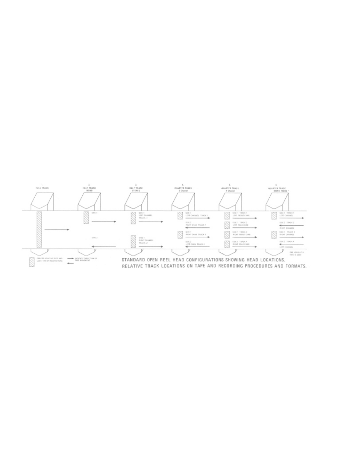
Tape Tracks and Channels of The Open Reel Tape
Decks
1. Full track recording: The magnetic flux pattern produced by the head covers almost the whole surface of the tape. The entire tape
is recorded in one direc tion only.
2. Half track monophon ic: The flux pattern generated by the head covers less than half of the tape surface and the recording head is
off-set to one edge of the tape. A monophonic signal is recorded on one half of the tape and then the reels are inter-changed and the
other half of the ta pe is record ed. The sam e half track head is used for both passes. T he tracks are, o f course, reco rded in opp osite
directions on the tape.
3. Half track stereo: Two recording sections (heads) are used to record two tracks simultaneously on the tape. Both channels are
recorded in the same direction on one pass through the tape.
4. Quarter track, 2-channel stereo: 2 record heads are used to record all 4 tracks on the tape. On the first pass through the tape, track
1 and 3 are recorded simultaneously. At the end of the first pass, the reels are inter-changed and tracks 2 and 4 are recorded using the
same two he ads that reco rded tracks 1 and 3. Th e actual prog ram on the tap e for tracks 1 an d 3, and 2 and 4 is reco rded in opp osite
directions but since the reels are inter-changed between passes, the tape is recorded and played in the forward direction for both passes
of the tape.
5. Quarter track, 4-track/4-channel (Qua draphonic): The head assembly consists of 4 separate heads and all 4 tracks can be
recorded at the same time on a single pass through the tape.
6. Quarter track, single channel (Mo nophonic): The 4 tracks on the tape are recorded one track at a time. At the end of each pa ss
through the tape the reels are interchanged and the next track is recorded. The order in which the tracks are recorded is 1, 4, 3 and 2.
Four track re cording gives maximum playback time however, the benefits of stereo reproduc tion are lost.
DIAGRAM A.
Playback compatibility
Diagram A shows the relative track locations and dimensions on a standard prerecorded 1/4" open reel tape. The playback heads
closely correspond to the record heads depicted in the diagram. Some decks in fact use the same record head for playback also. A brief
study of the track locations and recording sequence for the various common tape formats will lead to many valid conclusions
concerning compatibility between various tapes and tape decks. Some of these conclusions are stated briefly below.
1. A half track mono deck can playback a pre-recorded full track tape.
2. A half track stereo deck can play either a full track or a half track tape but the signal from a half track mono tape on side 2
will be played b ack in the op posite direc tion. However, the right channel output can be turned down and the left channel only
used for playback of both sides of the tape. When playing a furl track tape the left and right channel will reproduce the same
sounds.
3. A four track stereo tape dec k can playback both 4 track and 2 track tapes and from the point of compatibility has the widest
possible range of utilization. When playing a 2 track stereo tape on a 4 track recorder, track #1 will be completely covered by
the head. Track #2 will be slightly off alignment but stereo can still be enjoyed by compensating for the slight loss of track #2
volume with the volume or balance controls of the amplifier. On the other hand a four track tape cannot be played back on a
two track reco rder as bo th tracks #1 a nd #2, and #3 and # 4 will be repro duced together resulting in m ixed unintelligible
sound.
There are of course other possibilities for playback compatibility that the inventive audiophile or home recordist can discover by
consulting this diagram and o ther sour ces. The pr ocedures fo r rec ording in each of the v ario us formats will be covered in the O wner 's
Manual supplied with each TEAC deck. T his section is intended to give the interested recordist a complete overview of standard
recording tape forma ts.
Almost all tape decks are designed and constructed to record and playback only one of the standard formats. A few 4-channel decks
have a selectible 2-track playback head for compatibility with pre-recorded 2-track tapes. Full track and half track monophonic decks
for home use are rarely, if ever, available today. Full track professional decks may be purchased however.
Page 3
Introduction to Open Reel Tape Decks
Open Reel
Many articles have been written concerning the relative merits of open reel decks vs cassettes decks. Some of these articles have even
selected one or the other as being better. Our position, at TEAC, is that both types are excellent, can give good service and provide
many months and even years of recording and listening pleasure. A large number of audiophiles own both an open reel deck and a
cassette deck. Cassette decks have many advantages and features that continue to attract customers (especially convenience and price).
Open reel decks also have capabilities and features that appeal to many serious audiophiles. Here are some of them. Features such as
separate Record/Playback heads, Editing and cueing controls, mic-line mixing, monitoring functions, provide versatility for many
creative recording situations. The modern audiophile doesn't seem to be content to just record performances as they are. He or she
wants to create, to experiment, to modify. They want to put something of themselves into their recordings. The pro or semi-pro
recordist will find the high end performance and versatility a distinct advantage. Few, if any, records are made today directly from a
single live performance. A singer's voice is recorded at one time, instruments are added or changed, a chorus may be added and often
other special effects are mixed in. The final recording may be completely unrecognizable by the artist who sang the original song.
The higher speeds of the open reel decks make possible higher quality recordings which challenge the limits of one's entire stereo
system.
The quality, styling and price of open reel decks make them prestige items. A well designed open reel deck seems to blend in with the
most expensive furniture decor and even enhances the overall atmosphere of successful living. There are various head types and
configurations. Thi s sec tion is intend ed to give you a ba sic idea of ho w some o f the systems oper ate. Ple ase c onsult y our o wner's
manual for complete details of the features and capabilities of your deck.
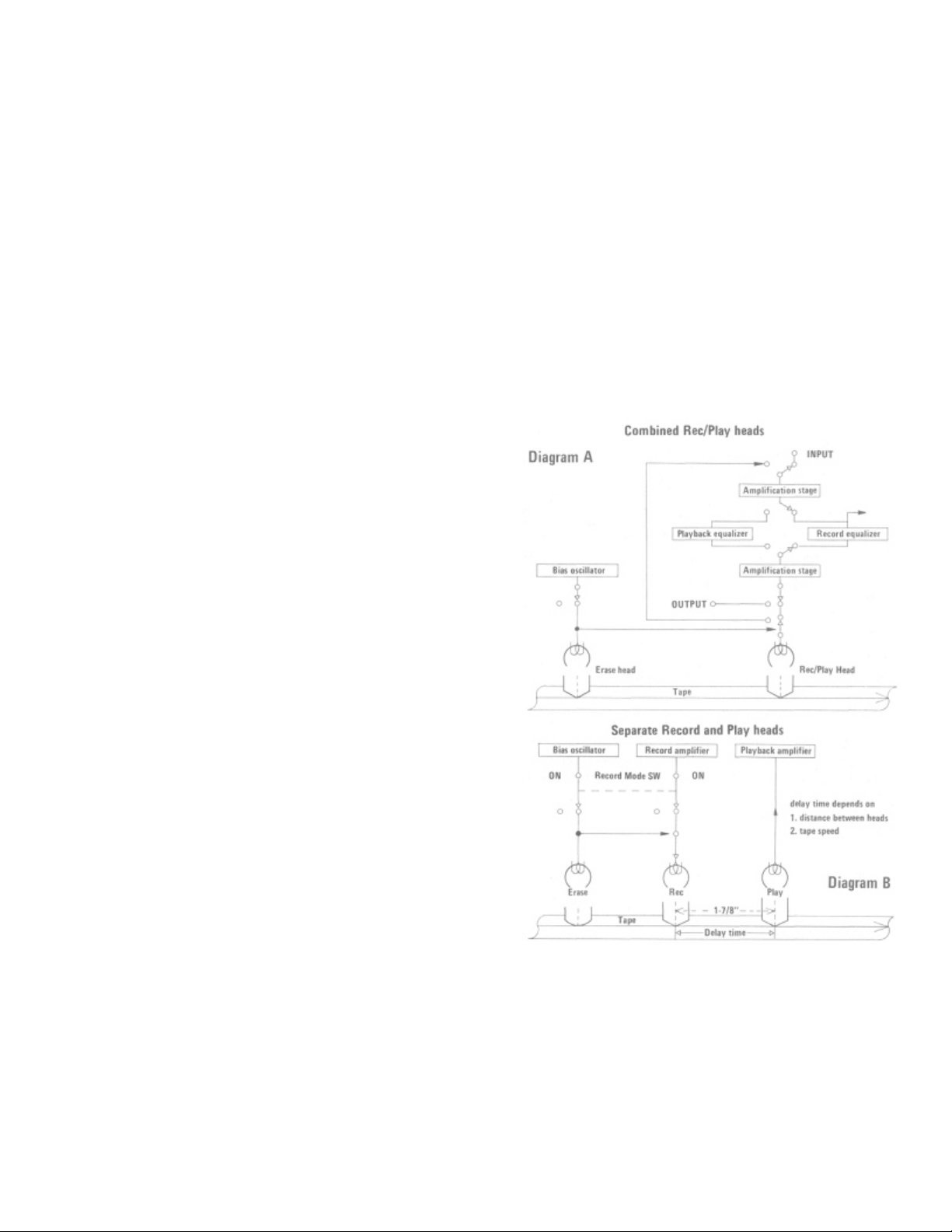
Earlier models of tape recorders used a combined Record/ Play head.
(Diagram A). With such a head, you cannot record and reproduce at the
same time. Another disadvantage of the combined head was in the design
of the width of the head gap. Modern head technology generally dictates
that the gap width should be different between the record and playback
functions for optimum output and frequency response.
When there are severe space and cost limitations, combined record/play
heads are still used today, and even though these heads are well designed
and highly efficient they still represent a compromise of optimum head
design. Open reel decks which normally have no head space limitations
and usually command a higher price due to their special cap abilities,
normally have separate R ecord and Play head s. (Diagram B). The sep arate
heads allow monitoring of the tape during recording. This system has
distinct advantages. You can insure that your tape is actually being
recorded properly as you record. The playback signal can also be
connected to the record head for special effects, such as sound-on-sound,
echo and sound-with-sound. (These techniques are explained on pp. 9,
10.)
With separate record and playback heads there will be a time delay
between the recorded signal and the reproduced signal. The delay depends
on two factors; the physical distance between the two heads and the tape
speed. For instance, if the record head and playback heads are 1-7/8" apart
and the tape speed is 3-3/4 ips, the delay is about 1/2 second. With the
tape speed increased to 7-1/2 ips; the delay is 1/4 second. At 15 ips the
delay is about 1/8 second. See diagram B.
For some recording situations, even this fraction of a second is not
acceptab le. If a musician or audiophile
wanted to add a new instrument or voice to a song already recorded and
wanted to listen to the record ed song for tim ing and synchro nization, this
delay would present a problem.
Page 4
Introduction to Open Reel Tape Decks (cont)
Editing and Cueing
Editing means to change a tape by physically cutting out unwanted sections of a recording or adding sounds by adding pieces of prerecorded tape. The cutting and rejoining of sections of tape is called splicing. Cueing means to locate a section of tape by listening for
the beginning or end of a rec orded section. High speed cueing is done by causing the tape to contact the playback head during fast
forward or rewind operation by retracting the tape "lifters." Manual cueing is done by moving the tape across the playback head by
turning the tape reels by hand. High speed and manual cueing are special features that are available on most TEAC open reel tape
decks.
MIC/Line Mixing
MIC/LINE mixing is a feature that allows the recordist to mix a line input and a microphone input together on the same track. An
internal mixer in the tape deck is required to accomplish this. You can add a live sound by MIC (your own voice or other sounds) to a
pre-recorded song connected to the LINE Inputs for real creative recording.
Monitoring function
Monitoring basically means to listen to the playback of a recording while recording. You can insure that the sound is actually going on
the tape properly without waiting until the tape is rewound and then played back. The deck must have separate REC and Play heads for
this monitoring function.
Splicing Tape
Editing tape is a fascinating way to make creative recordings by eliminating and joining different segments of a recording into one
pleasing tap e. Long, silent or boring segments can be rem oved by p roper editing. In fact, as editing is a creative exercise, the re is only
your imagination and the length of tape to limit the possibilities. Broken tape can also be easily mended by splicing, one of the steps
required in editing.
The first step is to precisely locate the section of tape to be removed.
On some TEAC decks this can be done by manually cueing the tape. Consult the Owner's Manual for operation of this feature in your
deck.
Next, use an Editing Block or a pair of scissors (demagnetized) to cut the tape at the places marked. Finally, the splicing is to be done.
A Tape Splicer is preferred, but a pair of scissors that have been demagnetized will be satisfactory. Before you proceed, have some
commercially available Splicing Tape available. Never use Cellophane (Scotch Brand) tape, for that adhesive will spread and
contaminate your head s.
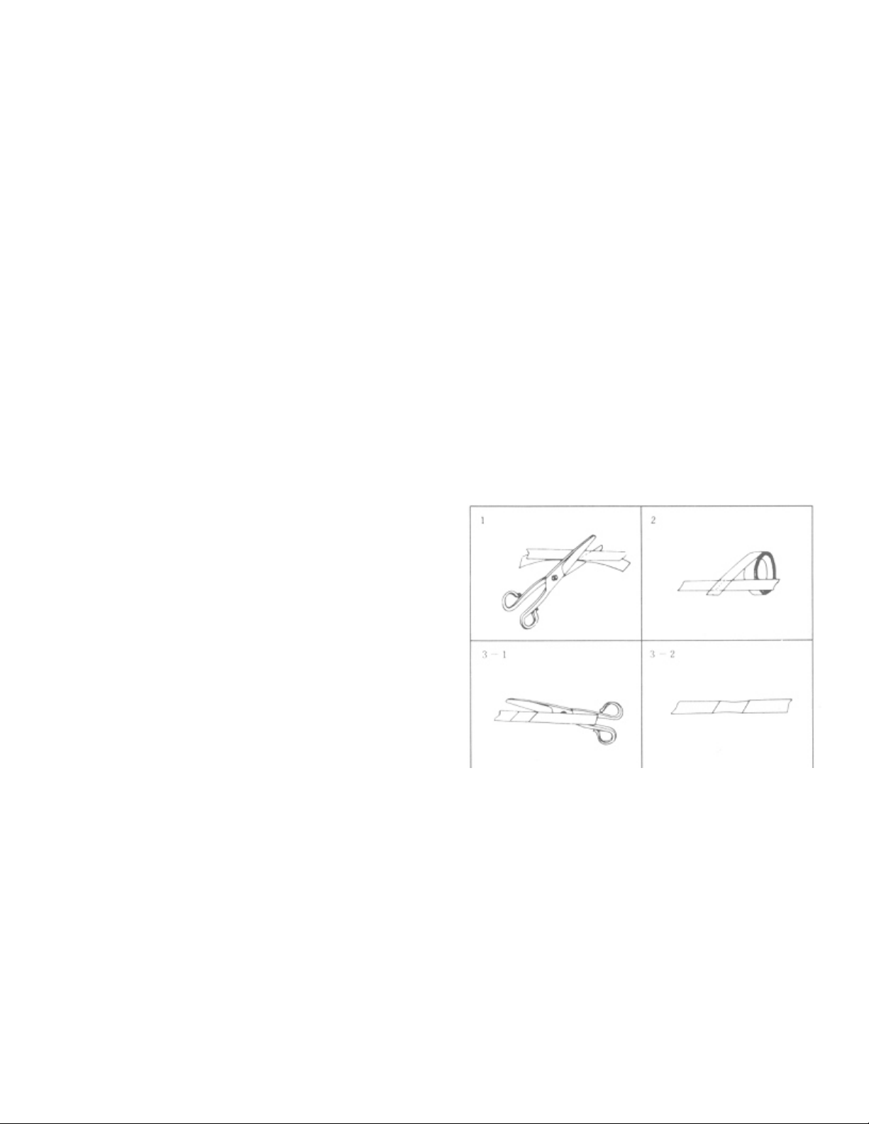
1. Overlap the ends to be spliced by approximately ½ inch and align
them carefully.
2. Cut through the center of the overlapped area at a 45 to 60 degree
angle.
3. Butt the slanted ends of the cut tape together. Use a straightedge or
ruler to assure a perfectly straight alignment.
4. Apply splicing tape to the shiny base side of the tape (opposite to the
tape side that touches the head) as shown in diagram 2. Note that
splicing tape goes perpendicular to the recording tape.
5. Place the spliced connection on a hard surface and rub the splicing
tape briskly with your fingernail or o ther hard sm ooth object. This is to
assure a firm adherence to the splicing tape.
6. Trim off the excess splicing tape as shown in Fig. 3-1 and 3-2. Note
how to cut slightly into the recording tape to insure complete removal of
the excess.
IMPO RTANT: Editing will destroy or seriously "cut" any material recorded on the other side of the tape (tracks 2 & 4). If editing is
anticipated, record only on one side of the tape. After editing, material can then be copied onto both sides of another tape. When
attaching blank "leader" tape onto your tapes, follow the same procedures given here for splicing.
Page 5
Bias and Equalization-General Theory
Bias
In order to get the magnetic particles on a tape to respond properly to the changing signal supplied to the record head, a preconditioning bias is needed. Most home recorders today use an alternating current (AC) bias at a frequency of 50 to 150kHz. This bias
raises the magn etic level of the o xide particles so that even small changes in the signal from the record head will cause relatively
similar changes in the magnetic level of the particles on the tape. Without this bias pre-conditioning, the oxide particles do not respond
properly to the signal from the record head. This high frequency bias signal is applied to the tape together with the desired audio signal
by the record head. Since the bias signal frequency is much higher than the audio frequency range, there is little chance that the bias
signal will interfere with the sound reproduction.
The amount of bias (bias level) affects the signal-to-noise ratio, distortion and the frequency response of the tape and hence of the deck
itself. Too little bias w ill allow more d istortion than is ne cessary. Bias also affects the output lev el of the tape. N ormally, as bias is
increased the signal level off the tape increases, up to a maximum output level which depends on the type and quality of the tape.
Increasing the bias level beyond this point causes the output level (and consequently, the S/N ratio) to decrease. The "optimum" level
of bias is usually a c omprom ise between the best results in S/N ratio, distortion and high frequency response, and usually differs with
different types and brands of tape. For this reason, all TEAC tape decks offer the user a switch selection for different bias levels or a
bias adjustment. One or the other of these is absolutely necessary if the recordist expects to use more than one type of tape. If everyone
used the same type and brand of tape, the tape deck manufacturers could all set their bias circuits for a specific type of tape and
everything would be fine. But, there are many good brands and types of tapes available and many recordists use more than one type of
tape. Experience and e xperimentation will help you decide which tape to use and what bias level is m ost appro priate
for specific situations.
TEAC offers charts and/or instructions on how to set the bias level for various brands of tape. These instructions should be followed
until the recordist developes sufficient knowledg e (and has the proper m easuring equipment) to make reliable tape evaluations.
Equalization
The EQ (equalization) selection must also match the type of tape formulation being used. If for instance, a deck was factory adjusted
for standard tapes and the recordist decided to use low noise/high output tapes with their accompanying high frequency emphasis, the
high frequencies would so und too bright.
The equ alization switch c an be used to reduce this high frequency over-emphasis an d restore the o utput signal to its orig inal fidelity.
Conversely, if the deck is factory adjusted for low noise/high output tapes and the recordist decided to use standard tapes, the high
frequencies will be much lower and an equalization setting that emphasizes high frequencies should be selected to compensate for
these low levels. TEAC tells in our instruction manual what equalization level should be selected for various types of tape. Together
with the bias setting, the suggestions sho uld be close ly adhered to until the audiophile develop es the experience and knowledge to
decide for himself.
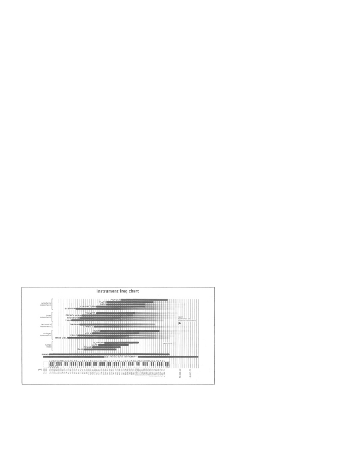
Frequency Response
Frequency response is one of many parameters or specifications that manufacturers consider in the design of their open reel tape
decks. But it is possible to over-emp hasize this one parameter at the exp ense of others, such as signal to-noise ratio. In general, it's best
to consider a well designed tape deck as a series of compromises that are made to give the best overall operation and performance. The
following musical sound frequency chart will help you understand the basic requirements of frequency response versus actual
recordable freque ncies.
Page 6

4-Channel Tape Decks
Introduction to Quadraphonic Sound
Propon ents of quad raphonic so und may overwhelm the newcomer with high sounding words like "sp atial effect, ambience, music hall
realism" or "surround sound". In simple terms, the philoso phy behind the emergence of quadraphonic sound goes like this.
When a perso n attends a concert or other m usical production in an auditorium or concert hall he hears sounds from many directions.
The primary or most significant sound originate from the direction of the orchestra, but there are also reflected sounds which one hears
from many other directions, including the sides, top and rear of the hall. The sound from the top and sides of the hall are often
insignificant because the primary sounds from the front tend to over-ride them. However, the sounds from the rear seem to add a
special dimension to the performance and give a sense of space and position to the listener. Without these rear sounds the "ambience"
of the auditorium would be lost and the listener would not enjoy the realism of being in the audience. To accurately record all of the
dimensions one "feels" at a live concert requires many channels but as a practical limit due to both space at home and financial
restrictions, 4 channels was determined to be the minimum number of channels required. These are the two front primary stereo
channels and two more rear channels that give the sense of position, ambience or "music hall realism".
Another use of 4-channel sound has also been investigated by some peo ple. This is "surround sou nd". Althou gh the "music hall
ambience" concept and "surround sound" are often considered the same thing, there is a difference. The music hall ambience concept
attempts to put the listener in the audience at a concert or musical performance. The idea is to faithfully record and reproduce the true
sounds an d realism of the hall. The sounds heard from each chann el are basically the same, with only a slight (though important)
difference in reverberation, volume level and acoustic phases.
Surround sound by contrast tries to put you in the band and even allows you to "walk through the band". The sounds on the 4 channels
are often quite different. A piano may emanate from channel 1, a bass may dominate channel 2 and channels 3 and 4 may contain other
sounds. The instruments and the volume levels may vary on each channel and the listener may get the impression that he is moving
around in the orchestra, some music experts call this type recording "gimmickry". Some others will say this type of 4-channel sound
provides vastly expanded creative possibilities.
Possible Spea ker arrangem ents
4-Channel speaker placement
In order to get the same sound ambience and emotional
atmosphere of the original recorded 4-channel mu sic logically
requires that the speaker layout be the same as the original
mike placement. For instance, if you record using a mike
arrangement as shown in Figure 1 A, your speaker
arrangement should be similar to 1 B. Acoustic properties of
the room or studio during recording versus these of the
listening room may cause some differences in the sound
experience. Since music is an emotional as well as a physical
experience you may want to experiment for the arrangement
that suits you best and gives you the greatest personal
satisfaction. Som e of the many possible speaker plac ements
are shown in Figure 2. The geometry and size of the listening
room will also affect the sound quality. A very small room will
severely limit the spa cing and place ment of your speakers. A
large listening room would offer more freedom of choice and
perhaps more problems with acoustics. One suggestion
concerning speaker placement in order to get faithful
reproduction of pre -recorded tapes is to try to picture your own
listening room in the original auditorium or recording area.
Page 7

The Tape-Record Time vs Length
The Tape
The length of a full reel of recording tape as well as the recording time, is determined by the reel diameter and the thickness of the
base mater ial.
The use of 1 or ½ mil base tape is recommended for 4 track high fidelity recording. Polyester base tape is preferred for use in humid or
extremely dry areas. Three recording speeds are commonly used, 3-3/4, 7-1/2 and 15 inches per second (ips). 15 ips is generally used
for produ ction of master tapes and for professional and semiprofessional use. 7-1/2 ips is commonly used for home high fidelity
recording. Generally speaking, the higher the recording speed, the better fidelity (especially at the very high audio frequencies).
However, due to the extremely high quality of the TEAC tape decks, recordings of excellent quality can be made at the lower speeds.
This provides maximum tape economy and extended playing time.
The recording time indicated in the charts below is for one single pass of the tape, therefore the total recording time will be either two
or four times that indicated, depending upon the method of recording (2 track stereo or mono-phonic).
7" reel
Base Tape len gth Recording time
7-1/2 ips 3-3/4 ips
1-1/2 mil 1200ft. 30 min. 60 min.
1 mil 180 0ft. 45 min. 90 min.
1/2 mil 2400 ft. 60 min. 120 min.
10-1/2" reel
Base Tape length Recording time
15 ips 7-1/2 ips 3-3/4 ips
1-1/2 mil 2400 ft. 30 min. 60 min. 120 min.
1 mil 3600 ft. 45 min. 90 min. 180 min.
1/2 mil 480 0 ft. 60 min. 120 min. 240 min.
Level Setting
Correct level setting of the MIC and LINE Input Controls will assure full frequency response, maximum dynamic range, minimum
amount of tape noise and the least possible distortion in your recorded tape. This is based upon the nature of magnetic recording tape
which has a useable recording range as shown in the chart below.
When the input level (an audio signal of a specified voltage) is very low
or weak, it must compete with the hiss and noise always present at the
same low level on the tape. Stronger input levels, are recorded above
this tape noise and tend to cover or "mask" it so you hear only the
desired sound during playback. If the input level is too high, it enters
the region shown at the top of the chart, which represents the limits of
the tape. This limit says that no matter how much stronger you record,
the tape can not accept and return the same strength of signal. The result
is known as "saturation distortion", and is heard as a garbled or harsh
sound. The dynamic range available is found betwee n this distortion at the high end and the noise at the low end . As the chart also
shows, there is a difference between recording tape. The tape on the left is representative of conventional or normal recording tape. To
the right is the improved kind of low noise/high output tape.
Input Level Controls (MIC and LINE) are used to match the strength of the input signal to the requirements of the tape. If the input
signal is a little too strong these controls must be adjusted to reduce it to prevent distortion. If the signal is a little too weak, the
controls must be set to increase the preamplification for raising the signal above the tape's noise level. Of these two limits, the
distortion caused by high level inputs is used as a reference for setting the controls. Generally speaking, the shaded area at the upper
(right side) of the V U meters' scale indicates that d istortion levels are being app roached. This area begins at 0 VU . As the ideal is to
record the p rogram without distortion of the loud parts o r losing the pur ity on the quieter p arts, the record ing level must co nsider both
limits.
Choice of Tape
Most ma gnetic tape av ailable com mercially today is clearly marked with its specifications, su ch as thickness, type of base material,
tape length (or reel diameter) and other characteristics.
Since TEAC open reel decks are factory adjusted for use with low-noise types of tapes as standard reference, we recommend that you
use the tape selection table printed in the Owner's Manual for selecting the tape to be used.
Page 8

Tape-Judging Condition and Handling
Tape condition can be judged by appearance when wound on the reel and viewed from the side.
1) Is it neatly wound? 2) Are there steps or irregularities in the winding? 3) Is the color of the base uniform as seen from the side? 4) Is
the tape edge smooth?
Selecting the tape and reel
For recording, new tape is not necessarily needed. If the tape is of good quality the erase head will erase the previous recording as the
new recording is made. However, avoid using tape whose coating is worn, peeled off or stretched.
If the color of the winding is different throughout the reel it is an indication that two different types of tape have
been spliced in. In some cases, the color may differ according to production lot even for the same type tape, or between opposite sides
of the wound tape.
Normal condition reel
The use of a good quality reel is an important point in preventing damage to the tape edge or uneven stretching. Always use reels of
the same diameter.
Judging tape condition by how it travels
Tapes w hich snake up and down between the g uides or over the heads will inevitably lead to level fluctuation and az imuth
misalignmen t.
Unevenly stretched tape which travels either higher or lower than the true path of the tape will in extreme cases drift off the pinch
roller.
Snaky motio n of an uneve nly stretched tap e is indicated b y the arrows.
Hang do wn a length of tape to chec k straightness
Tape Storage and Handling
Magnetic tape recordings are superior to phonograph discs because, with proper care, they can be kept and replayed for many, many
years without degradation. D uring playback, the biggest danger to the recording is a magnetized or dirty point on the deck, such as a
head or capstan. Ca re for the recording and the tape must be continued even after playing it by following these guides:
1. Protect the ta pe from dust
Keep it in the plastic bag and the original carton.
2. Protect the tape from heat
Do not pla ce it on top o f audio com ponents. Sto re it in a cool roo m but also av oid freezing te mperatures. Keep it out o f direct sunlight.
3. Protect the ta pe from stress
Tremendous pressure is built-up on the inner windings of tape. This pressure is acceptable unless you apply additional stress by
bending or squee zing the sides of the reels. This problem is increased if the windings are irregular. Frequent starts and stops will cause
uneven winding pressure and the tape will be unevenly wound from side to side within the reel. Slight pressure on the sides will then
break or crack the edge of the tape. Therefore, always prepare your tapes for long-term storage by re-winding them using the [ > ]
(forward) and [ < ] (Reverse) Playback operating speeds or the Uniform Wind speed (if your deck has this feature). The Fast Forward
and Rewind speeds normally apply a greater tape tension that is not recommended for tapes that will be unused for a long time.
4. Protect the tape from strong magnetic fields
Just as a Bulk Eraser will remove the recorded material, so will a permanent magnet or the voice coil of a speaker destroy your
favorite recording.
5. Protect the tape from humidity
Fungus growths will cause irreparable damage to the tape if stored in damp places. Keep the tape in the original plastic bag, but insure
that it is dry before storing.
Page 9

Special Recording Techniques
Sound-On-Sound Recording
The technique of recording sound on sound is basically a method for mixing the monophonic recording from one track with a
subsequent recording (generally live) on the second track (also monophonic). This procedure can be repeated from one track into the
other until the no ise level (tape hiss) from successive recordings has added to gether to an un desirable lev el, probab ly after five or six
recordings.
1. Make a monophonic recording on the Left channel (track 1).
2. Rewind the tape to the beginning of the recording.
3. Connect an audio cable from the Left channel OUTPUT jack to the Right channel LINE IN jack.
4. Insert a headphone plug into the PHONES jack and microphone into the MIC R (right) jack.
5. Place the RECORD - MODE L (left) switch OFF and the R (right) switch ON.
6. Engage the Rec ord/Pause mode by depressing the REC and PAUSE control buttons.
7. Reduce the Left LINE Level Controls and the Left MIC Level Control. Make a preliminary level setting with the Right MIC Level
control, using SOURCE Mo nitor.
8. Switch to TAPE-MONITOR. Release the Record Pause Mode by pushing the [REC] but ton.
9. Listen only to the Left earpiece on the hea dphones.
10. While monitoring the Left channel with headphones, make a mixed record ing by adjusting the MIC-R and LINE-R Level controls.
Observe the VU Meter (Right) but note that the reading will be slightly delayed because of the distance from the Record head to the
Playback head.
Sound-on-sound recording step chart
1st 2nd 3rd
MIC IN or LIN E IN jack
MIC or LINE Level Control L R L
MONITOR SELECT Switch
VU Meter L R L
REC. MODE SELECT Switch Left Right Left
OUTPUT L L R
Headphone Left Left Right
TEAC decks that have dual inputs and outputs facilitate Sound on Sound recording and make it possible to record Sound on Sound
with a Line Source as well as a Microphone Source as described above. Procedures for Sound on Sound with line are basically the
same as above; substitute "Right LINE" for "Right MIC" while maintaining the Right channel output stationary. For succeeding
recordings, simply reverse the chan nels each time, and use the alternate controls and switches.
If the LINE control does not provide sufficient adjustment you might re-adjust the OUTPU T contro l to prevent satu ration or to raise it
to a satisfactory level for recording. If the mixed recording on track 3 (right channel) is unsatisfactory, you may record it again, for the
original material still remains on track 1.
Sound-with-Sound
"Sound with So und", like sound on sound, involves recording monophonic material one track at a time on each of the two channels.
Unlike sound on sound, however, there is no mixing of the first track signal together with the second track recording. During playback
after the secon d recording, you will hear two distinct channels simultaneously but they will not be synchro nized nor have the affects
obtainable from stereophonic methods. Procedures are similar to monophonic recording, except the tape is rewound after the first track
is recorded so that the next recording is made parallel and in the same direction on the other channel. The first track is monitored
during the second reco rding to retain a relationship between the two c hannels.
For example, in language training, the student's response will be on the second track, re-recorded as often as desired, without
destroying the teacher's recording on track 1. Perhaps more common is to record music on one track and then add dialogue or
commentary on the other or vice versa. Music is generally not recorded "with" music, however, for the two recordings will not be
synchronized.
Another interesting use for the Sound with Sound recording technique is to produce your own personalized "sing-along" Play your
favorite record and record in monophonic on one channel. As you are recording you can add your voice to the other track via a MIC
input. During playback you can adjust the OUTPUT level of each channel to get the "best" blend of your voice and the original song
on the other track.
L R L
SOURCE
and TAPE
TAPE TAPE
Page 10

Special Recording Techniques
Echo Recording
The echo repetition cycle is strictly limited by the spacing between the Record head and the Playback (monitor) head, and by the tape
speed. The higher tape speed (7-1/2 ips) gives the quicker echo. Echo persistence (the number of repetitions) depends upon the
strength of recording. Persistence can be increased by increasing the OUTPUT Level setting. Avoid oversetting the Level for
saturation will begin when the echo becomes too strong. Set the MONITOR switch to TAPE.
Sound on Soun d and Stereo Echo Unit
Creative recording is especially enhanced with the versatile AX-10
Sound-o n-sound and Echo U nit. On standa rd 2-channel decks with
separate record and playback heads, you can produce sound-on-sound
and a wide range of echo effects including normal or "mono" echo and
stereo or "cross" echo.
The Model AX-10 Sound-on-Sound and Stereo Echo Unit is designed
to adapt a stereo tape recorder so that it can make sound-on-sound
recording s (mixing and recording from one track to the other) or apply
echo effects du ring record ing in stereo. Either process is simply
carried out by depressing the red buttons singly or in proper
combinations. This unit is adaptable only to stereo tape decks which
feature the ability to record on one track while playing back the
opposite track. In addition, decks with separate record and playback
heads and electronics are essential for the echo function.
With 4-channel decks, tw o AX-10's create dazzling quadra-son ic
effects — like rotating echo and psuedo-quad from stereo recordings.
Also recommended for 4-channel decks is the AX-20 Mix-down Panel. A hand-held studio console, the AX-20 converts 4-channel
recordings into 2-channel stereo masters and, with the level controls on the deck, can be used for mixing and blending selected
channels during recording.
Recording Directly from a Source
Although m ost connection diagrams show the tape deck connected directly
to a stereo amplifier, it is not necessary to limit yourself to that one source
for quality recording. In fact, almost any standard audio component may be
connected from its output to the LINE IN jacks of the deck with the
following exceptions.
1. Never connect the Speaker output of any amplifier to the deck.
2. Turntable and phonograph outputs need special amplification and
equalization from an amplifier before they can be recorded.
3. DIN cords are designed only for connection between the deck and a stereo
amplifier.
4. Electrical pickups for m usical instruments, electric guitars and electronic
organs are probably unacceptable. Check with your dealer or the unit's instruction manual before attempting to record directly from
these sources.
Dubbing (duplicating) tapes for yourself or others to enjoy is one of the many pleasures of tape recording. All that is needed is another
tape deck or player. Co pying may be d one from o pen-reel to o pen-reel, to cassette or to cartridge by conn ecting the output of one to
the input of another.
If possible, all copies should be made from one "Master" tape: either the original recording you have made or a first copy from a
spliced and edited tape. If c opy # 1 is used to make co py # 2, then #2 to make # 3, etc., the successive generations of copies tend to
accumulate a small amount of tape noise from each sequential copy. The primary key to maintaining high quality copies is having a
Master tape recorded at as high an input level (without distortion) as possible for maximum dynamic range. Other means to reduce the
small losses in dynamic range from tape hiss build-up include: (a) the use of Dolby Noise Reduction processing during the original
(Master) recording; (b) the use of good quality "low noise/high output" tapes at every stage of recording and copying; and (c) the
establishment of identical playback and recording levels while copying.
Page 11

* "DOLBY" and the Dolby Double-D symbol " DO ' trade marks of Dolby Laboratories Inc.
About Dolby NR
Dolby N oise Redu ction Units
The Dolb y Noise Reduction U nits are designed to reduce the h iss noise that is an inherent problem in the tape recording process.
When dubbing or copying tapes without some type of hiss reduction, the hiss from the two decks becomes cumulative and can become
a serious problem. Dolby noise reduction units reduce this noise by special circuits which overemphasize the mid and high range
sounds during re-recording and then reduce these same sounds (and the inherent hiss of the tape and the recording circuitry) during
playback.
Since Dolby circuits are licensed by Dolby Laboratories Inc., there are no significant differences in the basic function of the
various TEAC Dolby Noise Reduction Units. The primary choice of which unit to buy depends on the features, convenience of
operation and controls and the quantity and types of inputs and outputs desired. Dubbing with the Dolby Noise Reduction Unit When
dubbing a master tape it may be advisable to record the master tape through a Dolby Noise Reduction Unit as shown in the diagram
below.
Dolby Laboratories Inc. have developed an effective noise reduction system which reduces tape noise and hiss by as much as 10 dB.
This system is available from TEAC Corp. in the AN-60, AN-80, AN-180, AN-300 and other models. When using a Dolby Noise
Reduction Un it with a TEAC deck, note these following points:
1. Connect the Dolby NR unit directly to the deck. All audio cables from
the amplifier or other sources are then connected to the Dolby NR unit.
2. Unless specifically stated otherwise in the Dolby unit's Instruction
Manual, all instructions in this manual are still applicable. The type of tape
used in recording will determine the B IAS and EQ switch positions.
3. Before recording, be sure to perform the Dolby calibration procedure per
the instructions in the Dolby N oise Redu ction Unit's Owne r's Manual.
Playback of Dolby encoded tapes
When playing back a tape which was Dolby encoded on a deck which does
not have intern al Dolby circu itry, a separate D olby Noise Reduction Unit is
necessary. (Diagram N)
To enjoy the benefits of the Dolby N oise Reduction System both
recording and playbac k levels must be m atched. T herefore, "Dolbyencoded", "Dolby processed", or Dolbyized" tapes must be played back
through a properly calibrated Dolby Noise Reduction Unit, available from
TEAC a nd other compan ies.
Playback calibration for the Dolby NR System is simplified with the
TEAC Memory Marker Guides. The M-M guide on the OUTPUT
Control ca n be used to accurately mark the calibrated setting for quick re -establishment of the calibration.
Please note these points:
1. The Dolby NR System is not a filter and will not eliminate noises that
are present in the original recording.
2. Improvements in the recording tape itself (such as low noise/high
output tape ) have significantly reduced the inherent tape noise level.
Although the Dolby NR System is still contributing to an improved
signal to noise ratio when using these tapes, the advantages of the system
may not be so readily app arent.
When playing back a Dolby-encoded tape on a deck which has internal
Dolby circuitry, no external Dolby unit is needed. (Diagram O)
Page 12

Timer and Remote Control
Timer Contro lled Record and P layback TEAC makes a variety of timer control adaptors sold separately from the deck as accessories.
These timer control adaptors can be connected to the deck for automatic timed control of the Record and Playback functions of the
deck. Du ring your abse nce or while slee ping, your favo rite FM program can b e recorded; or awaken yourself to a rec ording of a
favorite song or music.
Carefully read the operating instructions enclosed with the timer control adaptor, which explain how to connect it to the de ck, how to
prepare the deck and set the recording levels for automatic, timed recording. After setting the timer control, push the [REC] or [Play]
button as de sired. When the timer reaches the designated time, record or playback will be started automatically wh en electricity is
provided by the AC clock timer con trol.
Remote Controlled Operation
To further enhance the flexibility and con venience of TEA C tape decks,
TEAC produc es many models of Remote Control Units. These u nits
allow you to control all or most of the transport functions from up to 15
feet away from the deck. You can control the deck from the comfort of
your easy chair or have freedom to move around during live recording
sessions.
For more specific instructions and capabilities of each of the timer
control adaptors and the remote control units, consult the operating
instruction man ual. The follo wing three illustration s will give you basic
hook-up information, pictorial views of the various units and a
compatib ility chart for many of the tape decks that TEAC sells
throughout the world. Be sure to get the correct unit that matches your
deck.
Timer Control Adapter/Remote Control compatibility chart
TEAC Model Remote Control Timer Control
A-2300SD RC-120
A-2300SR RC-140
A-2300SX RC-120
A-2340RS RC-140
A-2340SX RC-120
A-3300SR RC-140 RC-320
A-3300SX RC-120
A-3340S RC-120
A-4300SX RC-140
A-6100 RC-120
A-6300 RC-140
A-6600 RC-80
A-7300 RC-170
A-7300RX RC-170 RC-350
25-2 RC-170
40-4 RC-170
Adaptor
Page 13

Owner's Care
Cleaning and Degaussing
The single most important point in tape deck maintenance is frequent and proper cleaning of the heads. The heads should always be
cleaned before making important recordings and at least once for every 8 hours of use (record or playback). Dirty heads will cause a
reduction in high frequency response, irregular head wear, drop-outs and in extreme cases may cause the deck not to record at all. The
small amount of time and effort required will be more than compensated for by the higher quality of recording and reproduction
available if these procedures are followed.
Commonly used cleaning fluids are chlorothane, isopropyl alcohol and TEAC Head Cleaner (Fluid "A" in the TZ-261 kit).
Chlorothane is non-flammable and has excellent cleaning properties. Alcohol is harmless but is combustible and its cleaning properties
are lower. T EAC H ead Clea ning Fluid is non-toxic, non-combustible and has excellent cleaning properties and its use is
recommended.
Using a stiff cotto n swab or a p iece of gauze dipped in c leaning fluid, rub the entire head surface, being cautious not to scratch it.
Repeat the proce ss on each head until all discoloration and tape oxides are removed. Clean all metal parts over which the tape passes,
such as capstan shaft, tape guides, tape lifters, etc.
The cotton swabs should have a rigid shaft, a satisfactory job cannot be accomplished with the slender flexible types often seen.
During lon g periods o f use, the heads m ay become slightly magnetized . As a result, high freq uency respo nse will decrea se, noise will
develop, or in extreme cases, the high frequencies will drop-out or noise will be introduced into your valued pre-recorded tapes. To
keep your d eck opera ting with its original fide lity the heads shou ld thus be deg aussed at least on ce for every 5 0 hours of use, with i.e.,
TEAC mo del E-l Head Demagnetizer. Places specified for degaussing include each head, capstan shaft and guide post. Before
proceeding with the following steps move all the pre-recorded tapes sufficiently away from the degaussing area.
1. Turn OFF power to the deck.
2. Slide the switch of E-l ON, bring the tip close to the head and slowly mo ve it up and down four or five times.
3. Slowly draw it away from the head.
4. After finishing all points, turn OFF power to the demagnetizer only after it has been drawn at least 12 inches (30 cm) away from the
heads.
After prolo nged use the p inch roller will acc umulate a film of oxide. Use only Fluid "B " from the T EAC T Z-261 kit as it is esp ecially
formulated for cleaning rubber surfaces. Do not use chlorothane as it will cause deterioration of the rubber roller.
Note: The newer tape formulations leave a gray or white residue which is difficult to detect. Regular cleaning schedules should be
established rather than relying on observation.
Care of the wooden cabinet
Ordinary furniture cleaner and polish can be used to maintain the attractive finish.
Cleaning the Faceplate.
A soft cloth and mild cleaning fluids (non-ab rasive) can be used to restore the luster of the faceplate. An oil-damped cloth will also
give good results, but take care not to get oil on the tape path components such as the pinch roller, capstan, etc.
Page 14

Basic Trouble-shooting Chart
Basic troub le-shooting of an open reel tape deck is similar to trouble-shooting any other electrical or electronic equipment. Always
check the most obvious possible causes first including such things as: power cord, fuse, switch and control setting or position, proper
connec tions to the desired in put and outp ut sig nal, etc. Con sult your Owner's Manual for the correct operating procedure and
instructions.
Many of the most common problems are listed in the chart below.
SYMPTOM CORRECTIVE ACTION
Tape Transport
VU meter lamps do not illuminate when power
SW is turned on
No tape motion Is tape properly threaded and shut-off arm held in proper position?
Tape rubbing reel flanges Is reel properly seated, reel adap tor spacer installed or remove d per instructions,
Playback Operation
No sound. VU M eter shows normal indication. Are connections between tape deck and amplifier properly made?
No sound, no meter indication Check co nnections an d switch settings per procedure in Owner's M anual.
Poor so und quality Are heads clean? Is the tape in good condition and properly recorded?
Unstable sound. Same as above. Also, is pinch roller clean?
Recording
Does not Record Che ck switch settings and c on nect ion p er Recordi ng proc edure in the Owner's
Power cord connected, fuse ok?
tape in good condition?
Was tape actually recorded? Try another tape.
Manua l.
Does not Record, no audio at tape monitor but
OK at SOURCE
Monitored sound is poor, distorted, noisy, etc. Are Input levels properly set, BIAS/EQ Switches in correct position for the type
Record mode switches ON, tape in motion, heads clean?
of tape you are using?
Heads clean and demagnetized, tape in good condition?
Did you follo w correct R ecording procedure given in Owner's Manual?
Page 15

Tape Loading and Erasing
TEAC's "QUIK-LOK" reel holders
Always secure these reel holders before operating the deck to assure
adequate, solid support for the tape reels. Install the clamp adaptors for
10%" reels (when required) to the reel table before mounting the large
reels. Follow the procedures below for mounting 7" reels or the adaptors
onto the deck. Numbers given refer to the illustration.
A) Rotate sections 2 and 1 of the reel shaft fully counterclockwise.
B) Place the reel onto the reel shaft while slowly ro tating the reel CCW to
keep both tab sets in line.
C) When the reel is firmly seated on the reel table, turn sections 1 and 2
fully clockwise to secure the reel firmly in place. The tabs on section 2 of
the shaft should be centered between the slo ts on the reel.
10-1/2" reel clamp adaptor
When using large diameter tape reels use the reel clamp adaptor (TZ-
612).
1) Secure the reel clamp adaptor to the reel tables using the same
procedures as above.
2) Turn the locking knob of the adaptor fully CCW.
3) Align the 3 notches in the 10" reel hub with the 3 pair of detents on
the adaptor and push the reel all the way onto the adaptor.
4) Turn the locking knob of the adaptor tightly clockwise about 90
degrees until the reel is firmly secured to the adaptor. When removing
the reel from the adaptor, turn th e locking kno b CCW and use both
hands to carefully pull the reel off the adaptor. T his adaptor includes a
special spacer (shown in diagram A) which must be used when adaptor
is used with N AB Stand ard 10-1/2 " metal reels. T o use the adaptor with
Standard plastic reels, this spacer must be removed. Removal of the
spacer is quite easy
1) turn the ad aptor while ho lding the spac er until the ears of the spacer match the cut-outs at the back surface of the adaptor 2) lift
spacer off of the adaptor 3 ) keep the spacer for future use with metal reels.
Erasing recorded tape
One of the a dvantages of recording tape over records is that it can be recorded over and o ver again. T his raises the que stion of how is
the previous recording removed. Here are three different ways to erase earlier recorded material. Automatic erasing and recording: As
the photo sh ows, there is an E rase head lo cated to the left o f the Record head in your d eck. Its function is to purge the tracks of all
previous recording by means of a strong alternating magnetic field immediately before the tape reaches the Record head. This is done
automatically whenever you select record mode in the deck.
Erasing with the deck: Yo u may erase the entire tape track (s) at a time with no recording by rotating the M IC and LIN E level con trols
fully to MIN. and/or disconnecting the input connections. Start the deck in the Record Mode and tracks selected (by MODE switched
ON) will be erased.
Bulk erasu re: TEA C's Mode l E-2 Bulk Tape Eras er (or its equiva lent)
will quickly erase th e entire tape in a few seconds. This is the only
satisfactory way to erase a previously recorded ½ or full track tape to
prevent undesirable "cross-talk" or chatter from the former material. For
complete d irections on ho w to use, consult the instruction supplied with
the Bulk Eraser.
Page 16

Lubrication and Optional Accessories
Use TE AC TZ-255 oil or equivalent.
Lubricate points listed below at every 1,000 hours of operation or once a year if equipment is infrequently used.
CAPS TAN S HAFT: Remove the dust cove r by turning it counterclockwise with fingers, apply approximately 2 drops of oil to the oilchamber fe lt.
PINCH RO LLER SHA FT: Unscrew the cap with fingers, apply one drop of oil to the shaft bearing.
CAUTION: Do not apply excessive quantities of oil, over lubrication can be a source of difficulty. Do not apply oil to any rubber
parts. Should oil be spilled onto rubber parts, remove immediately with TEAC rubber cleaning fluid.
Lubrication should be accomplished immediately after use while equipment is still warm.
After applying lubricant, leave tape deck in horizontal position for 1—2 hours until oil is thoroughly absorbed.
Optional Accessories
MC-106L
Dynamic
Microphone
HP-120
Stereo Headphones
RE-1002
10-1/2" Metal Reel
RE-701
7 inch Plastic Reel
(large hub)
RE-711
7 inch Metal Reel
(small hub)
RE-702
7 inch Plastic Reel
(small hub)
TEAC,
The leader. Always has been.
TEAC CORPOR ATION: 3-7-3, Naka-cho, Musashino, Tokyo, Japan Phone: (0422) 53-1111
TEAC CORPOR ATION OF AM ERICA: 7733 Telegraph Road, Montebello, California 90640 Phone: (213) 726-0303
TEAC AUSTRALIA P TY.,LTD.: 165 Gladstone Street, South Melbourne, Victoria 3205, Australia Phone: 699-6000
PRINTED IN JAPAN • O58OK4 • D-2223AM
 Loading...