

Page 1
DM-24
Digital Mixing Console
Professional
9101439701
OWNER’S MANUAL
Ü
The lightning flash with arrowhead symbol, within an equilateral triangle, is intended to alert
ÿ
Ÿ
This appliance has a serial number
located on the rear panel. Please record
the model number and serial number
and retain them for your records.
Model number
Serial number
the user to the presence of uninsulated “dangerous voltage” within the product’s enclosure
that may be of sufficient magnitude to constitute a risk of electric shock to persons.
The exclamation point within an equilateral triangle is intended to alert the user to the presence of important operating and maintenance (servicing) instructions in the literature
accompanying the appliance.
CAUTION: TO REDUCE THE RISK OF ELECTRIC SHOCK, DO NOT
REMOVE COVER (OR BACK). NO USER-SERVICEABLE PARTS INSIDE.
REFER SERVICING TO QUALIFIED SERVICE PERSONNEL.
WARNING: TO PREVENT FIRE OR SHOCK
HAZARD, DO NOT EXPOSE THIS
APPLIANCE TO RAIN OR MOISTURE.
Page 2

Important Safety Precautions
IMPORTANT (for U.K. Customers)
DO NOT cut off the mains plug from this equipment.
If the plug fitted is not suitable for the power points in your home or
the cable is too short to reach a power point, then obtain an
appropriate safety approved extension lead or consult your dealer.
If nonetheless the mains plug is cut off, remove the fuse
of the plug
inadvertent connection to the mains supply.
If this product is not provided with a mains plug, or one has to be
fitted, then follow the instructions given below:
IMPORTANT: The wires in this mains lead are coloured in
accordance with the following code:
WARNING: This apparatus must be earthen.
As the colours of the wires in the mains lead of this apparatus may
not correspond with the coloured markings identifying the terminals
in your plug proceed as follows:
The wire which is coloured GREEN-and-YELLOW must be
connected to the terminal in the plug which is marked by the letter
E or by the safety earth symbol ç or coloured GREEN or GREENand-YELLOW.
immediately, to avoid a possible shock hazard by
GREEN-AND-YELLOW : EARTH
BLUE : NEUTRAL
BROWN : LIVE
and dispose
For U.S.A
TO THE USER
This equipment has been tested and found to
comply with the limits for a Class A digital device,
pursuant to Part 15 of the FCC Rules. These
limits are designed to provide reasonable
protection against harmful interference in a
residential installation. This equipment generates, uses, and can radiate radio frequency
energy and, if not installed and used in
accordance with the instruction manual, may
cause harmful interference to radio communications.
Operation of this equipment in a residential area
is likely to cause harmful interference in which
case the user will be required to correct the
interference at his own expense.
CAUTION
Changes or modifications to this equipment not
expressly approved by TEAC CORPORATION
for compliance could void the user’s authority to
operate this equipment.
The wire which is coloured BLUE must be connected to the terminal
which is marked with the letter N or coloured BLACK.
The wire which is coloured BROWN must be connected to the
terminal which is marked with the letter L or coloured RED.
When replacing the fuse only a correctly rated approved type should
be used and be sure to re-fit the fuse cover.
IF IN DOUBT — CONSULT A COMPETENT ELECTRICIAN.
For the consumers in Europe
WARNING
This is a Class A product. In a domestic environment, this
product may cause radio interference in which case the user
may be required to take adequate measures.
Pour les utilisateurs en Europe
AVERTISSEMENT
Il s’agit d’un produit de Classe A. Dans un environnement
domestique, cet appareil peut provoquer des interférences
radio, dans ce cas l’utilisateur peut être amené à prendre
des mesures appropriées.
Für Kunden in Europa
Warnung
Dies is eine Einrichtung, welche die Funk-Entstörung nach
Klasse A besitzt. Diese Einrichtung kann im Wohnbereich
Funkstörungen versursachen ; in diesem Fall kann vom
Betrieber verlang werden, angemessene Maßnahmen
durchzuführen und dafür aufzukommen.
2 TASCAM DM-24
Page 3
IMPORTANT SAFETY INSTRUCTIONS
CAUTION:
…Read all of these Instructions.
…Save these Instructions for later use.
…Follow all Warnings and Instructions marked on the audio
equipment.
1) Read Instructions — All the safety and operating instructions should
be read before the product is operated.
2) Retain Instructions — The safety and operating instructions should
be retained for future reference.
3) Heed Warnings — All warnings on the product and in the operating
instructions should be adhered to.
4) Follow Instructions — All operating and use instructions should be
followed.
5) Cleaning — Unplug this product from the wall outlet before cleaning.
Do not use liquid cleaners or aerosol cleaners. Use a damp cloth for cleaning.
6) Attachments — Do not use attachments not recommended by the
product manufacturer as they may cause hazards.
7) Water and Moisture — Do not use this product near water — for
example, near a bath tub, wash bowl, kitchen sink, or laundry tub; in a wet
basement; or near a swimming pool; and the like.
8) Accessories — Do not place this product on an unstable cart, stand,
tripod, bracket, or table. The product may fall, causing serious injury to a
child or adult, and serious damage to the product. Use only with a cart,
stand, tripod, bracket, or table recommended by the manufacturer, or sold
with the product. Any mounting of the product should follow the manufacturer’s instructions, and should use a mounting accessory recommended by
the manufacturer.
9) A product and cart combination should be moved with care. Quick stops,
excessive force, and uneven surfaces may cause the product and cart combination to overturn.
10) Ventila ti on — Slots and openings in the cabinet are provided for ventilation and to ensure reliable operation of the product and to protect it from
overheating, and these openings must not be blocked or covered. The openings should never be blocked by placing the product on a bed, sofa, rug, or
other similar surface. This product should not be placed in a built-in installation such as a bookcase or rack unless proper ventilation is provided or
the manufacturer’s instructions have been adhered to.
11) Power Sources — This product should be operated only from the
type of power source indicated on the marking label. If you are not sure of
the type of power supply to your home, consult your product dealer or local
power company. For products intended to operate from battery power, or
other sources, refer to the operating instructions.
12) Grounding or Polarization — This product may be equipped with a
polarized alternating-current line plug (a plug having one blade wider than
the other). This plug will fit into the power outlet only one way. This is a
safety feature. If you are unable to insert the plug fully into the outlet, try
reversing the plug. If the plug should still fail to fit, contact your electrician
to replace your obsolete outlet. Do not defeat the safety purpose of the
polarized plug.
13) Power-Cord Protection — Power-supply cords should be routed so
that they are not likely to be walked on or pinched by items placed upon or
against them, paying particular attention to cords at plugs, convenience
receptacles, and the point where they exit from the product.
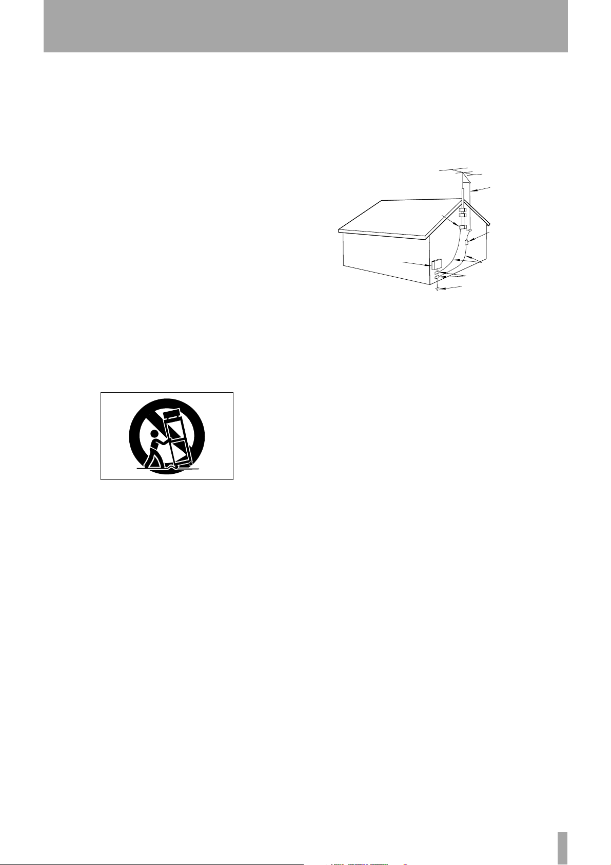
14) Outdoor Antenna Grounding — If an outside antenna or cable
system is connected to the product, be sure the antenna or cable system is
grounded so as to provide some protection against voltage surges and builtup static charges. Article 810 of the National Electrical Code, ANSI/NFPA
70, provides information with regard to proper grounding of the mast and
supporting structure, grounding of the lead-in wire to an antenna discharge
unit, size of grounding conductors, location of antenna-discharge unit, connection to grounding electrodes, and requirements for the grounding electrode.
“Note to CATV system installer:
This reminder is provided to call the CATV system installer’s attention to
Section 820-40 of the NEC which provides guidelines for proper grounding
and, in particular, specifies that the cable ground shall be connected to the
grounding system of the building, as close to the point of cable entry as
practical.
Example of Antenna Grounding as per
National Electrical Code, ANSI/NFPA 70
ANTENNA
LEAD IN
WIRE
GROUND
CLAMP
ANTENNA
DISCHARGE UNIT
(NEC SECTION 810-20)
ELECTRIC
SERVICE
EQUIPMENT
NEC - NATIONAL ELECTRICAL CODE
GROUNDING CONDUCTORS
(NEC SECTION 810-21)
GROUND CLAMPS
POWER SERVICE GROUNDING
ELECTRODE SYSTEM
(NEC ART 250. PART H)
15) Lightning — For added protection for this product during a lightning
storm, or when it is left unattended and unused for long periods of time,
unplug it from the wall outlet and disconnect the antenna or cable system.
This will prevent damage to the product due to lightning and power-line
surges.
16) Power Lines — An outside antenna system should not be located in
the vicinity of overhead power lines or other electric light or power circuits,
or where it can fall into such power lines or circuits. When installing an
outside antenna system, extreme care should be taken to keep from touching such power lines or circuits as contact with them might be fatal.
17) Overloading — Do not overload wall outlets, extension cords, or
integral convenience receptacles as this can result in risk of fire or electric
shock.
18) Object and Liquid Entry — Never push objects of any kind into
this product through openings as they may touch dangerous voltage points
or short-out parts that could result in a fire or electric shock. Never spill
liquid of any kind on the product.
19) Servicing — Do not attempt to service this product yourself as opening or removing covers may expose you to dangerous voltage or other
hazards. Refer all servicing to qualified service personnel.
20) Damage Requiring Service — Unplug this product from the wall
outlet and refer servicing to qualified service personnel under the following
conditions:
a) when the power-supply cord or plug is damaged.
b) if liquid has been spilled, or objects have fallen into the product.
c) if the product has been exposed to rain or water.
d) if the product does not operate normally by following the operating
instructions. Adjust only those controls that are covered by the operating
instructions as an improper adjustment of other controls may result in
damage and will often require extensive work by a qualified technician to
restore the product to its normal operation.
e) if the product has been dropped or damaged in any way.
f) when the product exhibits a distinct change in performance – this
indicates a need for service.
21) Replacement Parts — When replacement parts are required, be sure
the service technician has used replacement parts specified by the manufacturer or have the same characteristics as the original part.
Unauthorized substitutions may result in fire, electric shock, or other
hazards.
22) Safety Check — Upon completion of any service or repairs to this
product, ask the service technician to perform safety checks to determine
that the product is in proper operating condition.
23) Wall or Ceiling Mounting — The product should be mounted to a
wall or ceiling only as recommended by the manufacturer.
24) Heat — The product should be situated away from heat sources such
as radiators, heat registers, stoves, or other products (including amplifiers)
that produce heat.
TASCAM DM-24 3
Page 4

Table of Contents
1 – Introduction
Features ........................................................ 8
Supplied accessories .................................... 9
About this manual ....................................... 9
How this manual is arranged .................................9
Word clock issues ...................................... 11
2 – User interface
Scope of controls ....................................... 12
Global screens ....................................................... 12
Module screens ..................................................... 12
PODs ....................................................................13
Fine value settings using the PODs .....................13
Other ways of changing values ........................... 14
Using the faders to change values ...................... 14
Soft keys ................................................................ 15
Soft key pull-up menus .........................................15
Rotary encoders (ring LEDs) ...................... 15
Encoders used as EQ gain controls ...................... 16
Encoders used as EQ frequency controls .............16
Encoders used as Q controls ................................. 16
Encoders used as pan controls .............................17
Encoders used as aux send controls .................... 17
Fader layers ................................................ 18
Machine control keys ................................ 18
Automation keys ....................................... 18
Automation status ................................................ 19
3 – System-wide options
OPTION screen ........................................... 20
SETUP ....................................................................20
UPPER BAR DISPLAY ................................................20
LOCATE DISPLAY MODE .........................................20
ENCODER OPERATION MODE .................................20
LIBRARY DIRECT KEY OPERATION ..........................20
OL/STATUS LED TYPE ..............................................20
FADER SENSITIVITY .................................................21
METER CALIBRATION ..............................................21
PREFERENCES .........................................................21
Fader Auto MODULE Select ....................................21
Select MODULE Return ...........................................21
ST Link by SEL key ...................................................21
Balance Level CENTER: 0dB .....................................21
SEL Key Follows Fader Layer Status ......................21
Meter Follows SEL key ............................................22
Automation fader OFF ............................................22
Cursor follows EQ Band Key ..................................22
FLASH Info. ..............................................................22
Version Info. ............................................................22
Battery Check ..........................................................22
SOLO ....................................................................22
MODE SELECT ..........................................................22
SOLO LINK ................................................................22
SOLO TYPE ...............................................................23
INPLACE SOLO DEFEAT ...........................................23
SYNC/TC .................................................................23
DTRS Remote Timecode ..........................................23
RS-422 IN Timecode .................................................23
TRA Target link ........................................................23
Automation synchronization source .....................23
TC IN .........................................................................23
MIDI IN MTC .............................................................24
INT. ...........................................................................24
INT. START TIME ......................................................24
FLY WHEEL (frames) ...............................................24
DIGITAL screens ..........................................24
CLOCK settings ......................................................24
High sampling frequency ....................................... 25
Fs Status ..................................................................25
D-IN MANUAL SETUP ..............................................25
WORD SYNC IN ....................................................... 25
TDIF interfaces ........................................................25
ADAT ........................................................................25
AES3 .........................................................................25
CASCADE MASTER ..................................................25
Word phase ............................................................. 25
Checking the clock sources ...................................25
Out of range clock signals ....................................26
The FORMAT screen ..............................................26
Type of DIGITAL IN connection ..............................26
Other digital input parameters .............................. 26
Digital output .......................................................... 26
Multi I/O settings .................................................... 26
Stereo out setup .....................................................26
SLOT screen ............................................................27
4 – Parts of the DM-24
Top surface .................................................28
Analog module inputs ...........................................29
Other analog I/O ....................................................29
Module control section .........................................30
Library section .......................................................30
Parameter control section .....................................31
Monitoring section ................................................32
Module faders and selection, etc. ........................33
Transport and automation control .......................33
Rear panel ...................................................34
5 – Setting up the I/O
Signal sources .............................................36
Sixteen mic/line analog inputs ..............................36
Three TDIF connectors ............................................36
ADAT connector ......................................................36
DIGITAL IN 1 & 2 ...................................................... 36
Card slots ................................................................. 36
Assignable returns ..................................................36
Internal effectors .................................................... 36
Output signals ............................................37
Eight output busses ................................................37
Six aux busses ......................................................... 37
Stereo master outputs ............................................37
Direct outputs .........................................................37
Physical outputs .....................................................37
TDIF-1 connectors ...................................................37
ADAT OUT connector ............................................. 37
Slot cards ................................................................. 37
Assignable sends ....................................................37
Digital outputs (x 2) ................................................37
STEREO OUTPUTS (L, R) ..........................................37
Patching between input and return .........37
Assigning inputs to channels ....................38
Input sources ..........................................................38
Return modules .....................................................39
Digital inputs .........................................................39
Channel-to-buss assignments (global) .....40
Master settings ....................................................... 40
AUX 1-2 ....................................................................40
Channel-to-buss assignments by channel ...........41
Other module parameters ....................................41
4 TASCAM DM-24
Page 5

Table of Contents
Output assignments ...................................42
Digital outputs .......................................................42
Assignable sends and returns ...................43
Master compressors ...................................43
6 – Hookup
Analog connections ....................................44
MIC/LINE connections ...........................................44
External dynamics processors and effectors .......45
Analog monitoring and mastering ...................... 45
Digital connections .....................................46
DTRS recorder connections ...................................46
ADAT connections .................................................47
Digital inputs and outputs ....................................47
Synchronization and control connections 47
Word sync clock connections ................................ 48
MIDI connections ...................................................48
SMPTE/EBU timecode connections .......................48
Meter unit ..............................................................48
P2 connections .......................................................48
7 – Module operations
Selecting modules ......................................49
Common area indicators and controls ......50
Dynamics controls .................................................50
Gate/Expander ........................................................ 50
Compressor ............................................................. 50
Compressor insert point ......................................... 50
Dynamics meter ...................................................... 50
Other common controls and displays ..................51
Digital trim and pan ............................................... 51
Phase switch ........................................................... 51
Assignable inserts ................................................... 51
Input/return assignments ...................................... 51
Meter ....................................................................... 51
EQ and buss assignments ...................................... 51
Fader section ........................................................... 51
Mute and fader groups .......................................... 51
Digital trim control ................................................51
Pan control ............................................................. 51
Balance controls for stereo linked pair ................52
Global pan ..............................................................52
Ganging ................................................................... 52
Setup ....................................................................... 52
Dynamics screen .........................................53
Noise gate (GATE) .................................................53
Compressor ............................................................53
Expander ................................................................53
EQ ............................................................54
On/off (all bands) ................................................... 54
Gain (all bands) ....................................................... 54
Frequency range (all bands) .................................. 54
Q (all bands) ............................................................ 54
EQ band type .......................................................... 54
High band ................................................................ 54
High-mid band ........................................................ 54
Low-mid band ......................................................... 55
Low band ................................................................ 55
EQ library ...............................................................55
Aux sends ....................................................55
Aux sends (global) .................................................55
Fader control ........................................................... 56
Setup ....................................................................... 56
Copy ......................................................................... 56
Source (pre/post and SOURCE) settings ................56
Setup ........................................................................56
Linked aux sends .....................................................56
Setup screen ...............................................57
Channel source (CH SOURCE) .................................58
Gate switch (GATE SW) ...........................................58
Aux 1 and 2 source (AUX 1-2 SOURCE) ..................58
Compression insert (COMP INSERT) .......................58
Compressor switch (COMP SW) .............................58
Assignable insert position (ASSIGN INSERT) .........58
Assignable insert switch (ASSIGN INS SW) ...........58
Phase switch (
Digital delay time (DELAY) .....................................58
Digital delay units (UNIT) .......................................59
Φ
) .....................................................58
Digital trim and delay (global) .................. 59
Global digital trim ................................................ 59
Fader control ...........................................................59
Setup ........................................................................59
Global digital delay .............................................. 59
Unit ...........................................................................60
Fader control ...........................................................60
Setup ........................................................................60
PRE/POST .................................................................60
Linked modules .......................................... 60
Channels ..................................................................60
Master modules .......................................................60
Linking and unlinking modules ........................... 60
Stereo linking (global) .......................................... 61
Screens for linked modules .................................. 61
Phase ........................................................................61
Pan ............................................................................61
Mono switch (MONO SW) ......................................61
UTILITY copying ......................................... 62
8 – Dynamics processors
Turning the processors on and off ...................... 63
DYNAMICS (input channels 1–16) ............. 63
Selecting a gate or an expander ......................... 63
“Master” settings .................................................. 64
GATE/EXPAND .........................................................64
LINK L->R ..................................................................64
Trigger source ..........................................................64
Compressor ..............................................................64
Insert point ..............................................................64
LINK L->R ..................................................................64
Trigger source ..........................................................64
Soft keys (library) ................................................. 64
DYNAMICS (channels 17–32) ..................... 64
DYNAMICS (master channels) ................... 65
No expander or gate ...............................................65
Insert point ..............................................................65
Linking .....................................................................65
Assigning processors to master channels ........... 65
Dynamics diagram ..................................... 66
Gates/expanders ........................................ 66
Gate .................................................................... 66
Threshold .................................................................66
Range .......................................................................66
Hysteresis .................................................................66
Gate attack time ......................................................66
Gate hold time .........................................................66
Gate decay time ......................................................66
Expander ............................................................... 66
Threshold .................................................................66
Ratio .........................................................................66
TASCAM DM-24 5
Page 6

Table of Contents
Attack .......................................................................66
Release .....................................................................66
Compressors ............................................... 67
Threshold .................................................................67
Compression ratio ...................................................67
Attack time ..............................................................67
Release time ............................................................67
Auto make-up ..........................................................67
Output gain .............................................................67
Preset library entries ................................. 67
Compressors .......................................................... 67
Gates/Expanders ................................................... 68
9 – Grouping
Mute groups .............................................. 69
Turning groups on and off ...................................70
Copying mute settings to the faders ...................70
Fader groups .............................................. 70
Fader groups to mute groups .............................. 71
Turning groups on and off ...................................71
Grouping layers ......................................... 71
10 – Monitoring
Control room monitoring .......................... 73
Control room outputs ...........................................73
Control room signal selection .............................. 73
2-track input ..........................................................74
Studio monitoring ..................................... 74
Studio monitoring volume ................................... 75
Soloing ....................................................... 75
MODE SELECT ........................................................75
SOLO LINK .............................................................. 75
SOLO TYPE ............................................................. 75
PFL ............................................................................75
AFL ............................................................................75
INPLACE SOLO .........................................................75
Inplace solo defeat ................................................ 76
SOLO level ............................................................. 76
Turning soloing on and off .................................. 76
Dimming and talkback .............................. 76
Slate settings ............................................. 77
Lineup oscillator .................................................... 77
Meters and faders ..................................... 77
Master meters ....................................................... 78
Channel faders ...................................................... 79
Meter and fader setup .......................................... 79
Fader level ...............................................................79
Meter ballistics (METER SETUP) ..............................79
11 – Machine Control/Location
Selecting devices for control .................... 80
Deleting devices from the list .............................. 81
Auto-detection of devices ....................................81
Selecting the control type for the devices .......... 81
STATE .......................................................................81
DEVICE ......................................................................81
ID ..............................................................................81
CHASE ......................................................................81
TRA ...........................................................................82
REC ...........................................................................82
Machine Control mapping memories ..................82
To use a machine control mapping ...................... 83
Viewing the transport mappings .........................83
Editing a mapping .................................................83
General parameters ...................................83
Program Change channels ....................................83
Program Change values ........................................84
General MIDI parameters ......................................84
MIDI OUT Active Sensing .......................................84
OUTPUT MTC when slaved ....................................84
RESET (ffh) ...............................................................84
MIDI filtering ..........................................................84
Serial output ..........................................................84
Edit Frames .............................................................84
Play Mode ..............................................................85
AUTO .......................................................................85
DEFERRED ................................................................85
IMMEDIATE .............................................................85
Cueing Mode ..........................................................85
Locate Preroll .........................................................85
Location memories .....................................85
Selecting the location point display .....................85
Storing a location memory “on the fly” ..............86
Manually entering and editing a location
memory ...............................................................86
Location to a location memory .............................86
Viewing a list of location memories ....................87
Manual location .....................................................87
Repeat play ............................................................87
Auto punch operations .........................................87
ALL INPUT and AUTO MON ...................................87
External control ..........................................87
Moving between screens ......................................88
DTRS devices ...............................................88
DA-98HR .................................................................89
DIGITAL INPUT .........................................................89
INPUT PATCH ........................................................... 89
OUTPUT PATCH .......................................................89
INPUT MONITOR .....................................................89
TRACK DELAY ..........................................................89
TIME MODE .............................................................89
TC REC ......................................................................89
TC Generator ........................................................... 89
Machine Offset ....................................................... 89
PUNCH IN/OUT ........................................................89
DITHER ..................................................................... 89
VARI SPEED .............................................................. 89
CLOCK ......................................................................89
DTRS mixer .............................................................90
DA-78HR .................................................................91
DA-98 .....................................................................91
DA-38 .....................................................................92
DA-88 .....................................................................92
MIDI controllers ..........................................93
MIDI faders .................................................93
12 – MIDI
Bulk dumps .................................................95
Bulk transfer of data from the DM-24 .................95
Bulk transfer of data to the DM-24 ......................96
Updating the system software .................96
Control Change messages to and from
the DM-24 ................................................96
MIDI Implementation Chart .......................98
13 – Library functions
Library concepts .....................................................99
6 TASCAM DM-24
Page 7

Table of Contents
Managing library entries ...........................99
Storing active library entries ................................ 99
Storing entries in a non-active library ...............100
Loading entries from an active library ..............100
Loading entries from a non-active library .........100
Library undo/redo ...............................................101
Setting and editing titles ....................................101
Libraries—snapshots ................................102
Protecting snapshot settings ..............................102
I/O SEL / BUSS ASSIGN ......................................... 102
GROUPING ............................................................. 102
OTHER .................................................................... 102
Snapshot “neutral” setting ................................. 102
Libraries—effects ......................................103
Libraries—dynamics processors ..............104
Preset dynamics entries—compressors .............. 104
Preset dynamics entries—gates .........................105
Libraries—EQ ............................................105
Preset EQ entries .................................................106
14 – Surround operations
Selecting a surround mode ......................107
Monitoring surround patterns ...........................107
Selecting a buss pattern .....................................108
Assigning modules ...................................108
“Pan” controls ...........................................109
Global boom levels (5.1 only) .............................110
15 – High sampling frequency
To select high sampling frequency ....................112
Constraints on other devices ..............................112
Channels, etc. ............................................113
High sampling frequency I/O .............................114
Monitoring ................................................115
Aux sends ................................................. 115
Channel stereo linking ............................. 115
Grouping ................................................... 116
Trim and delay ......................................... 116
Libraries .................................................... 116
Other screens ........................................... 117
16 – Options
Clock sources ....................................................... 118
Cascade card ............................................. 119
Setting up the cascade ....................................... 119
Use of the cascade .............................................. 119
Cascaded facilities .............................................. 120
Soloing and muting ..............................................120
Snapshots ..............................................................120
Automation ...........................................................120
MIDI Control Change ............................................120
Cascading and effects ........................................ 120
High sampling frequency considerations ......... 121
TDIF-1 card ................................................ 121
ADAT card ................................................. 121
AES3 card .................................................. 122
Input options ...................................................... 122
Output options ................................................... 122
AD/DA card ............................................... 123
Timecode display ................................................ 123
17 – Specifications
Analog audio I/O ...................................... 124
Digital audio I/O ....................................... 125
Miscellaneous I/O connections ............... 125
Equalization ............................................. 126
System performance ............................... 126
Physical characteristics ............................ 126
Dimensional drawing .............................. 127
Messages and troubleshooting .............. 127
Block diagram (normal sampling
TASCAM DM-24 7
Page 8

1 – Introduction
The DM-24 digital mixing console is designed to
provide you with superlative audio quality in today’s
digital audio recording environment, as well as ease
of use and flexibility to meet changing needs.
This Reference Manual is not intended to be read
from cover to cover, but we do suggest that you make
Features
The DM-24 includes many advanced features,
including:
• the sixteen long-throw motorized “channel” faders
are “layered”, allowing control of up to 32 mono
inputs (which may be “ganged” in stereo pairs),
eight buss sends and six aux sends in a compact
package
• in addition to the sixteen faders mentioned above,
one other dedicated motorized long-throw fader is
used for the stereo out buss
• the TASCAM TDIF-1 digital audio format and
other general digital audio formats such as ADAT,
AES/EBU, SPDIF, as well as high-quality A/D and
D/A conversion, are supported,
• Modular expansion slot facilities provide further
flexibility
• sixteen integral high-quality microphone amplifiers, with switchable phantom powering and 24-bit
A/D conversion
• the DM-24 is capable of accepting and transmitting
digital audio data in 24-bit format, allowing it to be
used with the HR series of TASCAM DTRS
recorders as well as the MX2424 recorder
• internal processing is carried out at floating 32-bit
resolution
• eight output busses and six auxiliary sends
• eight fader groups and eight mute groups
• grouping layers provide further flexibility in grouping arrangements
• all popular surround formats (2+2, 3+2, 5.1) as
well as stereo, are supported for final mixdown
• expansion with another DM-24 console using an
optional cascade slot card
• both 44.1 kHz and 48 kHz base sampling frequencies are supported, together with dual-frequency
support (88.2kHz and 96 kHz), with flexible clock
configuration
• each of the 32 analog input channels is equipped
with 4-band fully-parametric equalization and a
dynamics processor
yourself familiar with the contents of this section as
well as the structure of this manual, so that you can
find answers to questions when you need them.
If you learn a little about the key features and principles of operation now, before you start to use the
DM-24 it will save you time and trouble later on.
• the capability of acting as a remote controller for a
wide variety of devices using the DTRS remote, P2
or MMC protocol
• synchronization to SMPTE/EBU timecode and
MIDI timecode, and MIDI timecode generation
facilities, allowing location of connected recorders,
etc. and integration with the DTRS tape system
• full control room and studio monitoring facilities
are provided, along with an integral talkback
microphone and master bargraph meters
• graphical user interface, based on the successful
TASCAM series of digital mixing consoles, and
featuring a backlit LCD with a flexible POD-based
user interface
• “ring encoders” give instant visual feedback of key
EQ, pan and aux send settings
• integral Antares© Microphone Modeler technology, allowing the DM-24 to emulate the distinctive
characteristics of any of a wide variety of classic or
modern microphones, using any standard
microphone
• integral t.c.electronics reverberation technology,
providing full standard reverberation facilities
within the DM-24
• flexible digital multi-effector providing many standard effects without the need for outboard equipment or connections
• library facilities for snapshot mix settings, frequently-used EQ settings, effect settings, dynamics
processor settings, etc.
• MIDI control allows dynamic control of parameters through MIDI messages, so mix events can be
recorded on MIDI for replay, as well as snapshot
recall being linked to Program Change messages
• the DM-24 contains its own automation system,
allowing full real-time control of almost all mix
parameters with no need for connection to other
units
• an optional meter bridge unit provides channel and
master metering facilities through LED bargraph
displays which are switchable in “layers”
8 TASCAM DM-24 Reference Manual
Page 9
Supplied accessories
1 – Introduction—Supplied accessories
As well as the documentation supplied with the DM24, you should also have packed with the unit:
• A power cord
• A warranty card
• A list of authorized TASCAM service stations
About this manual
Please note the following typographical and other
conventions used in this manual:
• Physical “push” controls of the DM-24 are referred
to as “keys”.
• “Push” controls which are shown and used on the
screen are referred to as “buttons”.
• The names of keys and other connectors and controls of the DM-24 are given in the following typeface:
DYNAMICS.
• The names of on-screen buttons and other onscreen features, titles and prompts, etc. are given in
the following typeface:
LIBRARY DATA.
If any of these items is missing, contact your TASCAM distributor.
Retain the box and other packing material that came
with the DM-24 in case you need to transport it in the
future.
• The names of any physical keys, connectors and
controls of other devices are given in the following
typeface: REMOTE IN.
WARNING
“Warnings” give advice regarding a possible hazard to
equipment or personnel.
NOTE
“Notes” provide additional information which requires
special attention.
How this manual is arranged
In addition to this manual, we also provide a Quick
Reference Guide, which you can use to remind you
of the quick ways in which common operations are
carried out.
Even if you are familiar with the operation of mixers
and digital mixers, and even if you never usually read
instruction manuals, we suggest that you read the
first few sections of this manual. They will provide
useful background information for you as you use the
DM-24.
The other sections of this manual are more in the
nature of background reference, and contain information that you may not need for everyday working.
1 – “Introduction” on page 8 : This section.
It provides an overview of the DM-24, its operational
features, and the manual.
2 – “User interface” on page 12 : This sec-
tion explains how to use the DM-24 controls in order
how to access the different screens, change values of
parameters and so on.
this section in order to understand the way in which
these global settings will affect the way in which you
use the unit,
4 – “Parts of the DM-24” on page 28 : This
section introduces the different keys and controls of
the DM-24. Since many of the keys have more than
one function, which is determined by the software, it
is impossible to give a full description of the use of
each control in this section. A description of the top
and rear panel connectors is also provided,
5 – “Setting up the I/O” on page 36 :
Because the DM-24 is essentially a “soft” product,
many of the hardware features are not mapped to logical functions on a one-to-one basis. This section
explains the different mapping and routing options
available to you, and how to configure the DM-24 for
your individual requirements.
6 – “Hookup” on page 44 : Explains how to
connect the DM-24 to other equipment (analog and
digital audio, control and timing connections, etc.).
3 – “System-wide options” on page 20 :
There are a number of options available on the DM24 which affect the whole operation of the unit. See
7 – “Module operations” on page 49 : In
many ways, this can be regarded as the most essential
part of the manual. It explains how to carry out the
TASCAM DM-24 Reference Manual 9
Page 10

1 – Introduction—About this manual
operations that you would typically carry out with an
analog console (EQ settings, assigning channels,
making Aux sends, etc.).
8 – “Dynamics processors” on page 63 :
The DM-24 contains flexible digital dynamics processors which can be used in a wide variety of ways,
and these are treated in their own section here.
9 – “Grouping” on page 69 : The DM-24
allows channels to be grouped into fader and mute
groups. This section explains how to set up and use
these groups.
10 – “Monitoring” on page 73 : Using the
DM-24 in a studio situation demands an understanding of the relationship between the different outputs
and what is heard in the control room as well as the
studio. This section covers these topics, as well as the
flexible solo facilities provided with the DM-24.
11 – “Machine Control/Location” on
page 80 : The DM-24 can act as a remote control
unit for a wide variety of external devices, and provides MIDI timecode synchronization facilities. This
section provides a guide to these facilities, as well as
the way that the DM-24 can act as a location memory
and recall unit for these external devices.
12 – “MIDI” on page 95 : MIDI devices can be
used with Program Change and Control Change messages for remote control of the DM-24. In addition,
settings can be stored for later recall over a MIDI
connection using System Exclusive messages. This
section gives details of these facilities.
It also explains the procedures to be carried out if the
internal system software is to be upgraded.
13 – “Library functions” on page 99 : Var i-
ous settings (effects, EQ settings, snapshots and
dynamics processors) can be stored for later use in
internal libraries. Read this section in order to understand how to make the best of these facilities.
14 – “Surround operations” on
page 107 : The DM-24 is capable of performing
mixdown operations in various surround modes as
well as stereo. This section explains how to connect
and use the DM-24 for surround operations together
with the way in which it can be used for successful
surround mixing.
15 – “High sampling frequency” on
page 112 : The DM-24 can be used in high sam-
pling frequency modes (88.2k and 96k). This section
describes the differences when the high sampling frequency is selected.
16 – “Options” on page 118 : This section
provides you with a quick reference to the extra facilities available to enhance your DM-24. It also contains a list of the messages displayed by the DM-24.
Even though the DM-24 is relatively simple to operate, and should prove almost error-free in everyday
operation, you may need to refer to this section in
order to correct an abnormal situation.
17 – “Specifications” on page 124 : The raw
facts and figures concerning the DM-24. You may
need to refer to this section to discover the compatibility of the DM-24 with other equipment.
There is also a list of messages which may be displayed by the DM-24. You may use this to help you
understand what is going on when you see a message
displayed on the screen.
Index : We try to make the index a useful place to
look if you need help on a particular topic. Use the
index first when searching for an answer.
10 TASCAM DM-24 Reference Manual
Page 11

Word clock issues
1 – Introduction—Word clock issues
The “word clock” in a digital audio system is the timing information that enables the digital audio samples in a system to be synchronized between the
different devices. It is completely unconnected with
timecode clocks, etc.
There must be one, and only one, word clock master
device in a digital audio system. The DM-24 is capable of acting as a word clock master or as a slave.
WARNING
There should be one, and only one, word clock master
in a setup. Multiple word clocks in a setup may result in
noise. which can damage monitoring equipment
(speakers and amplifiers).
Check with the other equipment that you are using to
see whether it can be a master or slave, and work out
which device will be your word clock master. If the
DM-24 is to be a word clock slave in your system, it
can accept word clocks from the following sources:
• An external clock connected through the dedicated
connector
• The TDIF-1 interfaces
• The integral ADAT interface
• Either of the two
DIGITAL IN interfaces
• Either of the slots occupied by an optional digital
interface card. In the case of an AES/EBU interface
card, any of the four stereo signal pairs may be
individually selectable as the word clock source.
• If two DM-24 units are being cascaded, the clock
source on a cascaded DM-24 will always be the
cascade master DM-24 unit. The master of the cascade chain can select its clock from any available
source.
The clock can be at 44.1 kHz or 48 kHz or 88.1kHz
or 96kHz with some variation possible for varispeed,
etc. at ±6%.
NOTE
When the DM-24 is linked to an external word clock, it
can only use a base frequency clock. Even when many
external devices are operating at high sampling frequencies, they output such a base frequency clock. If
the external device does not do so, and only outputs a
high sampling frequency clock, the DM-24 must be used
as the word clock master for the system.
TASCAM DM-24 Reference Manual 11
Page 12
2 – User interface
Scope of controls
The DM-24 has three main types of control screen:
system screens, which control parameters for the
whole of the system, “global” control screens which
Global screens
As the name suggests, the “global” screens allow you
to see all the parameters for many channels (the prepost settings for Aux 3 in this example), and to edit
them using the POD system as explained here
(“PODs” on page 13).
affect a certain parameter for a number of channels or
modules at once, and the “module” control screens
controlling all the parameters for one module.
Sometimes a key will have two labels. The function
described by the lower label (white on blue) is
accessed by pressing the
SHIFT indicator is lit, and then pressing the appropri-
ate key.
In this example, the
MIDI/MC key when the SHIFT indicator is lit.
SHIFT key is a “smart” key. Pressing and releas-
The
ing it within a short time (somewhat less than half a
second) latches it on and off as shown by the indicator being lit.
SHIFT key so that the
EXT. CTRL key becomes the
These global display screens are selected using the
SCREEN MODE keys to the right of the display
screen.
Module screens
Alternatively, the screen can be used to show and set
the parameters of one module (similar to a channel
strip on a conventional console).
However, since the number of parameters and features available on the DM-24 is more than a single
screen can display, four screens are available for each
module, accessed through the soft keys (“Soft keys”
on page 15).
To use a module:
1 Press the
the display.
2 Use the soft keys (“Soft keys” on page 15) to
select a sub-screen (
SETUP).
MODULE key situated to the left of
DYNAMICS, EQ, AUX or
Pressing and holding the key for more than about half
a second and then releasing it will cause the indicator
to go out when the key is released (non-latching).
While the
(the white on blue) is always active.
4 Press the
SHIFT indicator is lit, the shifted function
SEL key of the module you want to
edit. The screen changes to show the settings
for the selected module:
3 Press the
module whose parameters you want to edit.
FADER LAYER key containing the
12 TASCAM DM-24 Reference Manual
Page 13
5 Use the cursor keys, the soft keys and the
PODs to make changes to the module’s
parameters. See below for details.
PODs
2 – User interface—Scope of controls
The DM-24 features four rotary controls immediately below the screen, called PODs.
These are used as “soft” controls to adjust parameters; that is, they have no fixed assignment to control
any single parameter in the console, but are used to
control a parameter which is currently highlighted on
screen.
The POD controls have no end-stop, but are continuously moveable. The value of the parameter controlled by the POD is shown by the graphical onscreen representation of the control.
As part of the POD system, cursor keys are included,
which move the cursor to the appropriate part of the
screen.
In addition, the dial can usually be used to move the
cursor around the screen. Usually when we mention
that the cursor keys can be used for navigation, the
dial can also be used, even when this is not explicitly
stated.
Use the § and ¶ keys or the dial to move the cursor
row (shown by a blinking box surrounding the row)
up and down. Sometimes in some global screens (as
shown here) the box does not cover the full width of
a screen row, and the Ó and Á keys or dial must be
used to move the box within the row.
When a number of on-screen controls are highlighted
by a box surrounding the row containing up to four
on-screen knobs, the appropriate PODs are used to
control the on-screen controls.
If the row also contains on-screen buttons, these are
“pushed” by using the Ó and Á keys or dial to navigate to the button in the row (if necessary), and then
pressing the
ENTER key.
Fine value settings using the PODs
By pressing and holding the 2ND F. key while turning a POD, the value set using the POD can be
changed more precisely.
This feature is useful when the parameter being
changed has many possible values (for example, the
digital delay setting) which are first set using the
default “coarse” setting, and then fine-tuned using
the fine mode with the
This feature can also be used with the rotary encoders (“Rotary encoders (ring LEDs)” on page 15) to
2ND F. key.
set values entered using these controls with more
precision.
There is also an option setting which allows PODs
and encoders to be used for fine setting of values
without the use of the
OPERATION MODE” on page 20). If this is
enabled, pressing the
POD or encoder changes values in “coarse” or accelerated mode.
2ND F. key (“ENCODER
2ND F. key and turning the
TASCAM DM-24 Reference Manual 13
Page 14
2 – User interface—Scope of controls
Other ways of changing values
The JOG/DATA dial can also be used to change
parameter values.
Checkboxes
On/off button
Radio buttons
Parameter values
edited without the
ENTER key.
1 Use the cursor keys to move the cursor
(sometimes shown by a blinking thick box
surrounding the parameter to be changed,
and sometimes by a
ƒ symbol beside the
parameter to be changed.
2 When the parameter to be changed is high-
lighted as described above, use the entry dial
to set the value (it starts to flash), and the
ENTER key to confirm the value set with the
dial.
Alternatively, if the parameter is an on-off
switching button or a checkbox (a number of
checkboxes can be checked individually),
press the
ENTER key when the cursor is next
to the button or checkbox.
If the parameter is a “radio button” (one of a
number of alternative options), simply highlight another radio button in the same group,
and press the
ENTER key to change the state
of the buttons in the group.
NOTE
In some screens, (for example the module screens), the
active area is marked by a flashing box. The dial is then
used for navigation, rather than for setting values.
There are other screens, where the dial is chiefly, but
not exclusively, used for navigation (e.g. the
SETUP
screen (“SETUP” on page 20). If the dial is used
for numerical data entry in such cases, it is necessary to
press
ENTER
the value with the dial, and
editing to confirm the value.
(the value flashes) before starting to edit
ENTER
once again after
OPTION
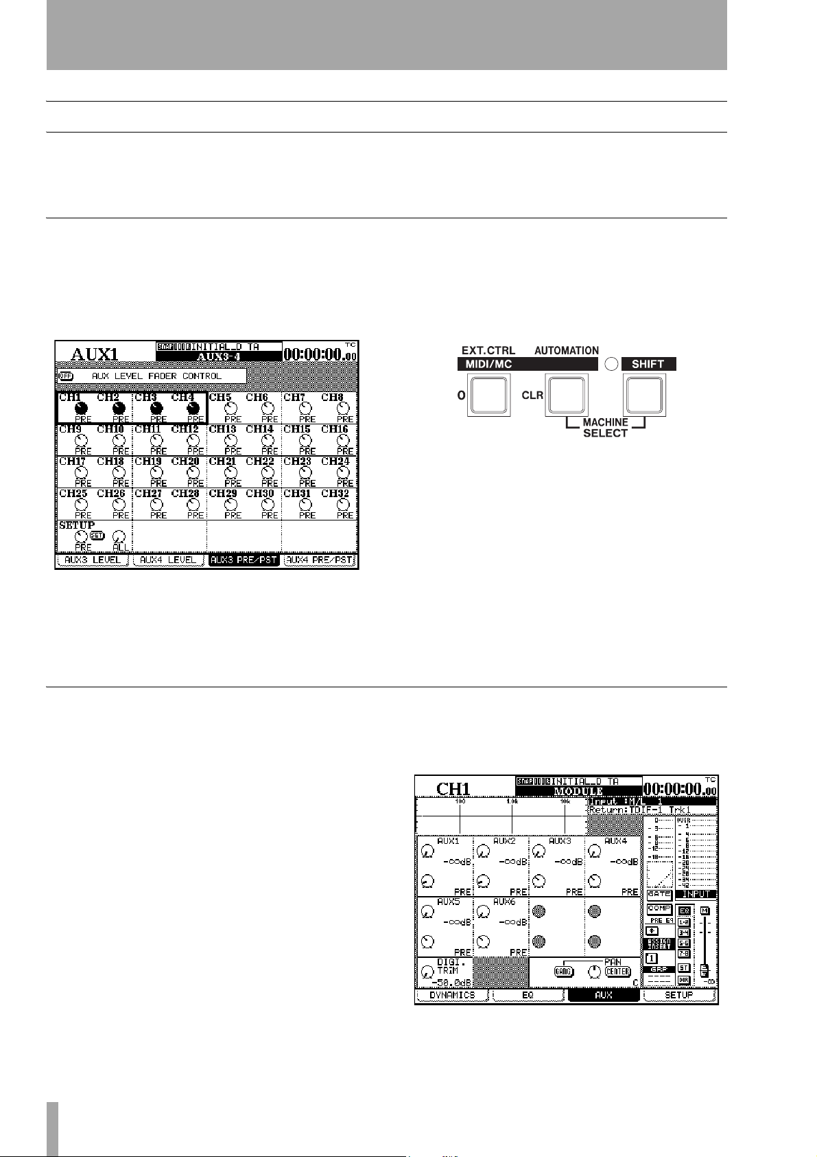
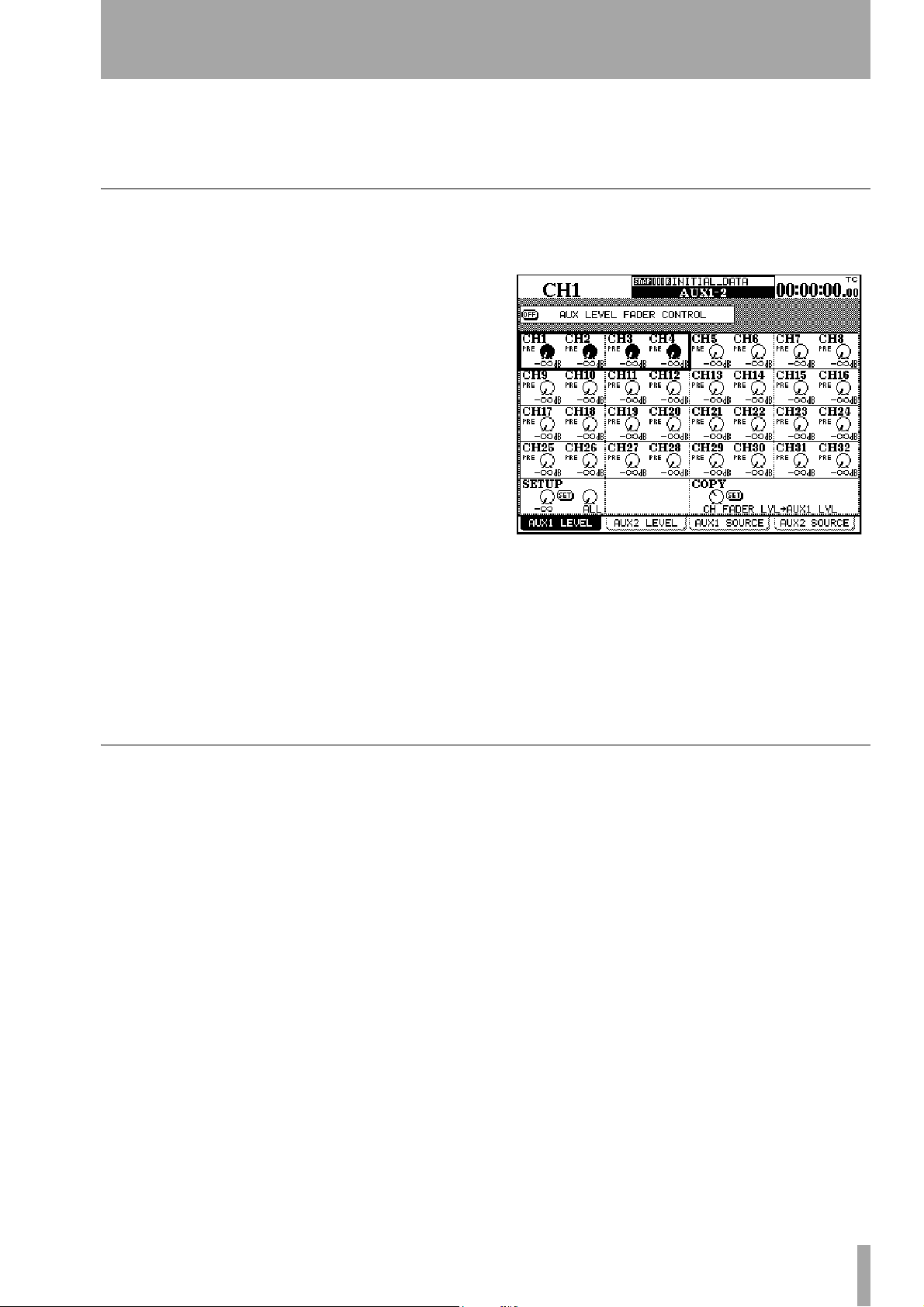
Using the faders to change values
In the global screens, there is often a special onscreen button, allowing the setting of the values in
the screen directly using the faders.
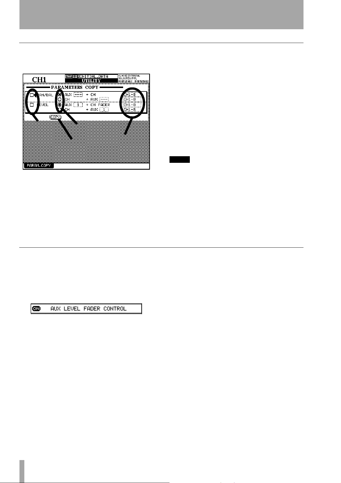
To enable this feature, turn the on-screen
CONTROL
button to ON.
The name of this button is prefixed by the title of the
screen (here it is an
AUX LEVEL screen which is being
edited).
When the button is turned on:
• The faders move to reflect the values set for the
current parameter
• The fader layer key starts to flash (if it is a channel
module layer and not the master layer—see “Fader
layers” on page 18). This flashing key shows that
the faders are not currently acting as channel faders
FADER
and that moving the faders will change the currently selected parameter, not the module’s signal
level.
• Moving the fader of a channel changes the value of
the current parameter.
• Using the POD to change the value of a channel’s
parameter moves the corresponding fader if the
layer is active. If the layer is not active, the fader
will be moved to the new position when the layer is
made active.
The status of the fader control setting is memorized
between screens (and even when the DM-24 is turned
off and on again). It is therefore possible for the faders to move when the screen is changed.
The layer continues flashing as long as the faders are
not controlling the channel levels.
14 TASCAM DM-24 Reference Manual
Page 15
Soft keys
2 – User interface—Rotary encoders (ring LEDs)
At the bottom of a display screen, there may be some
“tabs” displayed, which lead to further related
screens or pre-defined action.
Soft key pull-up menus
In a few screens, for example, the library screens,
where many soft keys are used for the “one-off”
actions, a soft key (usually soft key 1) is used to bring
up a small menu at the bottom of the screen:
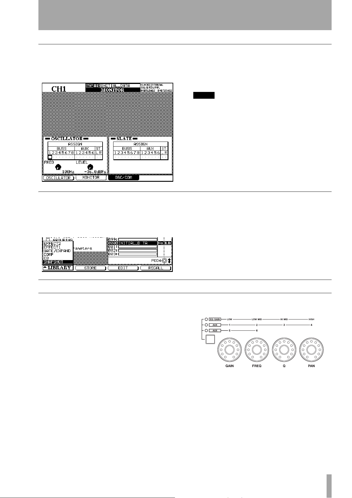
The four keys at the bottom of the screen, beside the
PODs, are used as “soft keys” to jump to the screens
shown on the “tabs”. In this example, the
and
OSC/COM tabs are controlled by soft keys 2 and 3.
NOTE
It is also possible to jump to the different screens by
repeated presses of the key which brings up the screen
(in this case, the
MONITOR
key).
MONITOR
These keys are sometimes used to perform a unique
“one-off” action, as shown in this screen, where the
oscillator can be turned on and off using soft key 1.
When such a menu pops up, either the dial or the
POD corresponding to the soft key (usually POD 1)
is used to select the desired option (which is highlighted in inverse video).
Rotary encoders (ring LEDs)
These controls allow you to set commonly-used
parameters such as EQ parameters, pan and balance,
and Aux send levels.
These are not dedicated controls, as the parameters
which may be controlled using them are changed
using selection keys, but their action is confined to
fewer parameters than the POD controls.
Like the PODs, these controls are continuously
moveable, and have no end-stop. Unlike the PODs,
though, the parameters that they control may not necessarily be shown on screen. In order to gain an indication of the current value, the eleven LED indicators
Use either the
ENTER key or the soft key which was
used to pull up the menu to make the selection from
the menu.
arranged in a ring around the knob light to show the
current value, as explained in the sections below.
These encoders have three different functions:
• EQ controls and pan controls to control the EQ
settings (gain, frequency and Q) as well as the current channel pan/balance of the currently active
module. In this mode none of the encoder indicators (to the left of the encoders) is lit, and the band
controlled is determined by the appropriate
EQUALIZER key.
TASCAM DM-24 Reference Manual 15
Page 16
2 – User interface—Rotary encoders (ring LEDs)
• EQ gain controls, where the gain of the four EQ
bands is adjusted using these encoders. The
encoder
EQ GAIN indicator is lit in this case.
• AUX send level controls, where either the encoder
AUX 1 through 4 indicators or the AUX 5 and 6
indicators are lit (in the latter case, only the two
leftmost encoders have any function).
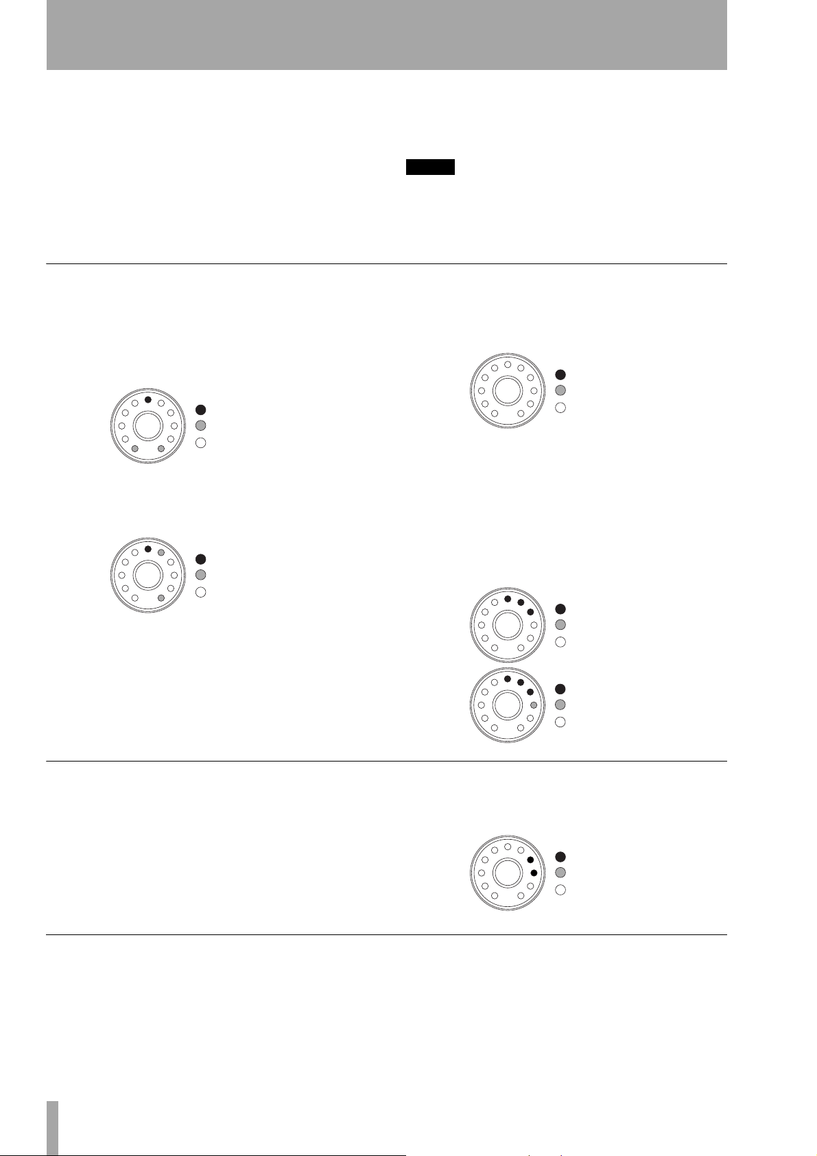
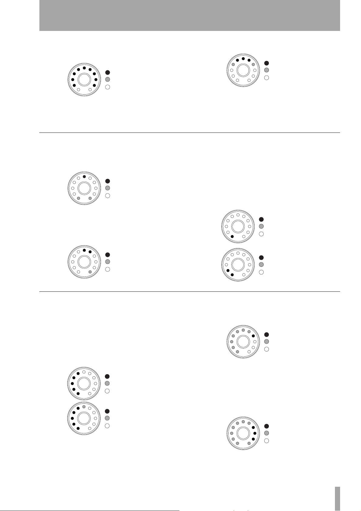
Encoders used as EQ gain controls
When the encoders are used as EQ gain controls, a
unity gain (neither cut nor boost) is represented by
the sixth (center) LED being lit, and the two LEDs at
the extreme clockwise and counterclockwise positions “half-lit” (dimmed).
= on
= dimmed
= off
When the encoder is near the center position, but not
quite there, the LED next to the center is lit, as well
as the “end” LED on the appropriate side:
= on
= dimmed
= off
See the appropriate section on module operations
(“Module operations” on page 49) for full details of
the parameters controlled here.
NOTE
The option described in “Fine value settings using the
PODs” on page 13 also affects the operation of these
encoders when used in conjunction with the
key.
2ND F.
If the EQ band is set as a high-pass for low-pass filter
or is used as a notch filter (depending on the band),
all LEDs around the rotary encoder are off:
= on
= dimmed
= off
When the encoder is turned either clockwise or counterclockwise, to boost or cut the gain respectively, the
end LEDs go out, and the LEDs on the appropriate
side of the center light (the more the cut or boost, the
more LEDs will light). “Half steps” are shown by
dimmed LEDs at the end of the chain. The illustrations below show a relatively small amount of gain
applied, and then a little more gain:
= on
= dimmed
= off
Encoders used as EQ frequency controls
When the encoders are used to set the frequency controlled by an EQ band, only one or at most two LEDs
are lit at any one time.
As the knob is turned clockwise, the ring LEDs light
in turn, representing the position of the knob
“pointer”. For greater accuracy, intermediate values
Encoders used as Q controls
The Q of an EQ band refers to the width of the filter
when it is in notch or peak mode (but not in shelf or
= on
= dimmed
= off
are shown by two LEDs being lit simultaneously, as
in the illustration below:
= on
= dimmed
= off
16 TASCAM DM-24 Reference Manual
Page 17
2 – User interface—Rotary encoders (ring LEDs)
filter mode). Low Q values affect a wide portion of
the spectrum, as shown below:
= on
= dimmed
= off
Encoders used as pan controls
When the encoders are used to make pan settings, the
center pan position is represented in the same way as
unity gain on the EQ gain controls:
= on
= dimmed
= off
“Almost center” positions are shown in a similar way
to the “almost unity” gain position (that is, the center
LED is lit, along with the LED immediately next to
it, with the end LED on that side being dimmed).
and high values affect a narrow frequency band:
= on
= dimmed
= off
Note that “intermediate values” are shown on the
encoders by dimmed LEDs, as above. The LED pattern in Q mode is always symmetrical about the
upper center indicator.
When the pan position is moved to either the left or
the right of center, one (or two, to represent intermediate settings) LEDs light to show the current pan
position.
The illustrations below show the pan position at the
hard left position, and then at a position just right of
hard left.
= on
= dimmed
= off
= on
= dimmed
= off
Encoders used as aux send controls
When the encoders are used as aux send controls and
the control is turned clockwise, the LEDs light up,
following the “pointer” of the knob.
The number of LEDs lit depends on the aux send
level relative to unity position (0.0dB).
Below this position, the LEDs light clockwise, with
intermediate positions shown by dimmed LEDs:
= on
= dimmed
= off
= on
= dimmed
= off
= on
= dimmed
= off
At the 0.0dB point, the LEDs representing values
below this point are dimmed, and the “0” LED lights.
= on
= dimmed
= off
When aux sends are set above the 0.0dB level, the
LEDs above the unity point light in sequence (intermediate positions shown by dimmed LEDs), with the
LEDs below the unity point being dimmed. The diagram here shows a setting just below maximum
(9.6dB):
= on
= dimmed
= off
TASCAM DM-24 Reference Manual 17
Page 18

2 – User interface—Fader layers
When two aux channels are linked together, the
encoders work in a slightly different way for the
selected channel. The first encoder (
the pan for the first two aux sends (
the second (
The third (
FREQ) controls the level for these sends.
Q) and fourth (PAN ) control the pan and
level respectively for aux sends
GAIN) controls
1-2 or 5-6) and
3-4 in the first AUX
encoder setting (they have no effect in the second
AUX encoder setting).
The operation of the pan settings is as described for
channel operations (“Encoders used as pan controls”
on page 17).
Fader layers
The DM-24 has sixteen physical “channel” faders
and one master fader. However, it is capable of
accepting more inputs than faders (up to 32 channels), and also has eight output busses and six aux
sends, which are often controlled on conventional
mixers using their own faders.
LAYER 12345678910111213141516
1–16
17–32
MASTER
a. Master fader
12345678910111213151516M
17 18 19 20 21 22 23 24 25 26 27 28 29 30 31 32 M
B1 B2 B3 B4 B5 B6 B7 B8 A1 A2 A3 A4 A5 A6 — — M
To allow the sixteen faders to control the different
parts of the console, the faders are arranged in “layers”. The layers are arranged as follows (as shown
above each fader on the console itself):
M
a
Use the
LAYER STATUS keys located to the right of
the master fader, to switch between the three fader
layers. The selected key lights and the keys are of different colors, as shown in the table above, so that it is
easy to see which layer is currently active, even from
a distance.
Machine control keys
As well as the keys controlling the DM-24 functions,
there are also dedicated keys to control external
devices connected to the DM-24.
Among these keys there are dedicated transport keys
which allow basic transport control, as well as controls for auto punch and repeat control of external
devices.
There are also
strip, which are used to arm tracks on a connected
device.
REC keys at the top of each channel
These fader layers also affect the use of the module
REC keys (used for arming the tracks of external
control devices), the
SEL keys, and the MUTE keys.
When the fader layer is selected, the faders move to
show the current status of the layer.
See “Machine Control/Location” on page 80 for full
details.
A strip of location keys to the right of the display
mode keys controls the location facilities on the connected machine. When these keys are used for location, the
NUMERIC ENTRY functions. The digits entered with
DISPLAY MODE keys take on their
these keys are labelled at the left of the keys.
These keys are also used to enter digits when naming
or renaming library entries (“Setting and editing
titles” on page 101).
Automation keys
The DM-24 has self-contained automation facilities.
The dedicated keys to control these functions are all
colored purple for easy identification.
18 TASCAM DM-24 Reference Manual
These keys are the AUTOMATION block by the transport controls, and the purple key near the rotary
encoders.
There is a separate “shift” key to control the second
function of some of the automation keys (and the
Page 19

2 – User interface—Automation keys
undo/redo function of the library. This key is the 2ND
F.
key (above and to the left of the rotary encoders).
These second functions are labeled below the key in
inverse lettering:
To use these second functions, press and hold the
2ND F. key and press the key whose second function
is to be used.
Press and
hold this key
and press
this key
to access
this function
(KEEP)
Automation status
As explained in the automation manual, the automation engine can be turned on or off in the main automation screen.
The
AUTOMATION UNDO key is used in automation
operations in order to undo any unwanted changes to
automated mixes.
The operation of the automation facilities is
explained in a separate manual.
When the automation engine is enabled, the word
AUTO appears at the top of the screen, together with
any automation mode currently enabled.
TASCAM DM-24 Reference Manual 19
Page 20
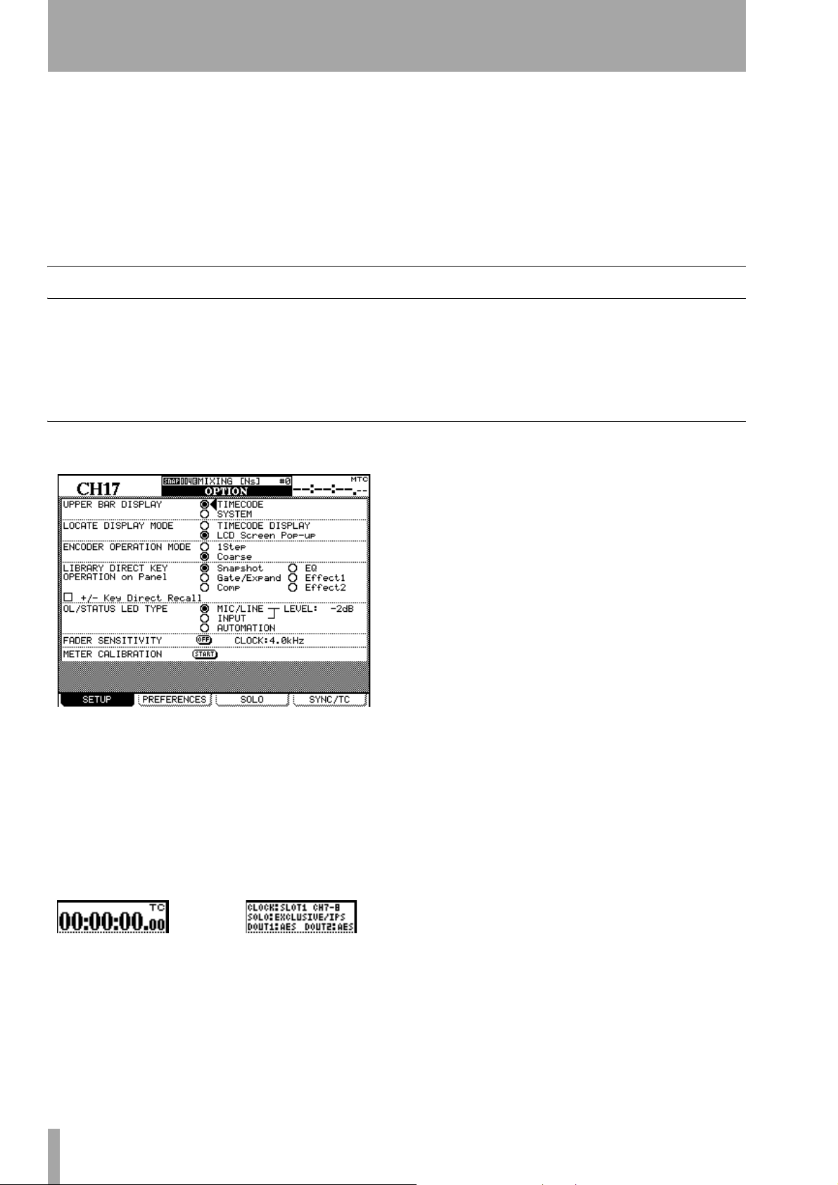
3 – System-wide options
The DM-24 provides a number of options which control the overall functionality of the console.
These are accessed through the
OPTION and DIGITAL
screens.
Within these screens, you can (in the
OPTION screen):
• Set up various interface preferences
• Set up the way in which soloing works
OPTION screen
To access the OPTION screen:
1 Press the
lit.
2 Press the
SETUP
The following options are available from this screen:
SHIFT key so that the indicator is
AUX 1-2/OPTION key.
• Set up timecode preferences for synchronization
with other units
and in the
DIGITAL screen
• Set up the word sync clock
• Choose the digital input and output formats
• Define and make settings for the optional slot cards
These options are described in detail below:
The screen changes to show the
OPTION
screen. There are four screens available using
the soft keys immediately below the display:
SETUP, PREFERENCES, SOLO and SYNC/TC.
ENCODER OPERATION MODE When using
the encoders (“Rotary encoders (ring LEDs)” on
page 15), or the PODs, the parameter being edited
may sometimes have too many values to allow easy
setting using the encoder (for example, there are 127
different pan positions). Using the
“click” of the encoders corresponds to one step in the
parameter values. Using the
changing of the parameter values to be accelerated,
with fewer clicks of the encoder.
1Step setting, one
Coarse option allows the
Use the § and ¶ cursor keys (or dial) to move the
cursor to the appropriate fields, and then press the
ENTER key to change the value.
UPPER BAR DISPLAY This parameter has two
options:
TIMECODE, the top right field of the display shows
incoming timecode, and when set to
system parameters (clock source, solo mode, etc.) are
displayed.
TIMECODE and SYSTEM. When set to
SYSTEM, certain
LOCATE DISPLAY MODE This parameter deter-
mines how a location entry will be shown on the display: in the timecode position (
as a separate popup display in the center of the screen
(
LCD Screen Popup).
TIMECODE DISPLAY) or
Holding down the
2ND F. key while turning the POD
or encoder reverses the usual acceleration mode (if
1Step is chosen, 2ND F. + POD/encoder = acceler-
ated, and if
Coarse is chosen, 2ND F. + POD/encoder
= accelerated.
LIBRARY DIRECT KEY OPERATION This
parameter controls the type of library accessed by the
RECALL and STORE, and the + and – keys in the
LIBRARY section to the left of the screen. There are
six choices:
tings,
for gate and expander effects,
processor settings for compression effects,
equalization setting library, and
Snapshot refers to the overall mixer set-
Gate/Expand to the dynamics processor settings
Comp to the dynamics
EQ to the
Effect1 and Effect2 to
the first and second internal effector settings, respectively.
+/- Key Direct box is checked, this allows instant
If the
recall of a library entry selected using the
+ and –
keys.
OL/STATUS LED TYPE The OL/STATUS LED
indicators above each fader can serve one of two purposes: firstly, if either of the two “overload” options
20 TASCAM DM-24 Reference Manual
Page 21
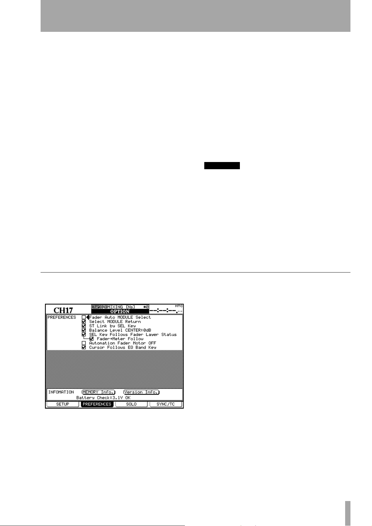
3 – System-wide options—OPTION screen
(MIC/LINE or INPUT) is selected, they act as overload
indicators when the input level exceeds the level set
in the
LEVEL field (OVER, 0, –2, –4, –6, –8, –10, –12,
–18, –30 or –42 (dB).
This status can be set for either the
through 16 or for the
INPUT associated with the mod-
MIC/LINE inputs 1
ule, using the appropriate radio buttons.
Set the level for the overload lighting by moving to
the value, pressing the
set the value and pressing
ENTER key, turning the dial to
ENTER to confirm the
value.
Otherwise, if the
AUTOMATION option is selected,
these indicators show the current automation status
of the channels, as explained in the automation
manual.
FADER SENSITIVITY This parameter allows you
to specify the sensitivity of the faders, as used in the
automation process.
The DM-24 touch sensing capabilities are dependent
on the ambient humidity and environment. Depending on these factors, it may sometimes happen that
faders which have been touched are not recognized
as having been touched, or the faders are recognized
as having been touched when they have not actually
been touched.
The value of the sensitivity is set by default to 4.0k,
but you may wish to set it to any of the following values:
1.0k, 1.5k, 2.0k, 2.5k, 3.0k, 3.5k, 4.0k (Hz). High
values mean higher touch sensitivity.
While the
switched
FADER SENSITIVITY on-screen button is
ON and this screen is visible, touching any
of the faders with your fingers will illuminate the
STATUS/OL indicator for as long as the fader is
touched. This provides a very useful check for the
sensitivity of the faders.
METER CALIBRATION Move the cursor to the
START button and press ENTER to start the process of
calibrating the DM-24 meters.
WARNING
You must turn down the headphone and control room
monitor levels before starting this check, to avoid any
possible damage to your ears and to the control room
monitoring system.
Press the ENTER key (or cancel the process using a
cursor key). After the meter calibration process has
finished (about 3 seconds), the message
calibration finished
appears as a popup message. You
can then restore the control room and headphone levels.
METER
PREFERENCES
The following general working preference settings
are available from this screen:
Fader Auto MODULE Select When enabled
and a
MODULE or DYNAMICS screen is shown, this
option allows a module to be selected whenever its
fader is touched, in addition to the usual method of
pressing the
option is enabled, the module shown at the top left of
the screen changes when its fader is touched.
SEL key. In other screens, when this
Select MODULE Return When checked, this
option allows the
module to appear if the
pressed and held for about two seconds.
MODULE screen of the appropriate
SEL key of the module is
ST Link by SEL key When checked, this option
allows the stereo linking of two adjacent modules
(provided the left module of the pair is odd-numbered) by pressing and holding the
module and pressing the
SEL key of the other.
SEL key of one
Balance Level CENTER: 0dB When two chan-
nels are linked together as a stereo pair, the pan controls change to a balance control, as mentioned
earlier. In the center position, the level may either be
set to 0dB (checked) or a 3dB cut (unchecked).
SEL Key Follows Fader Layer Status allows
the setup of the automatic linking of the selected
channel to the selected meter layer.
When this option is selected, if a channel is selected,
the fader layer is changed, and then the fader layer is
changed back again, the originally-selected channel
is automatically selected.
TASCAM DM-24 Reference Manual 21
Page 22
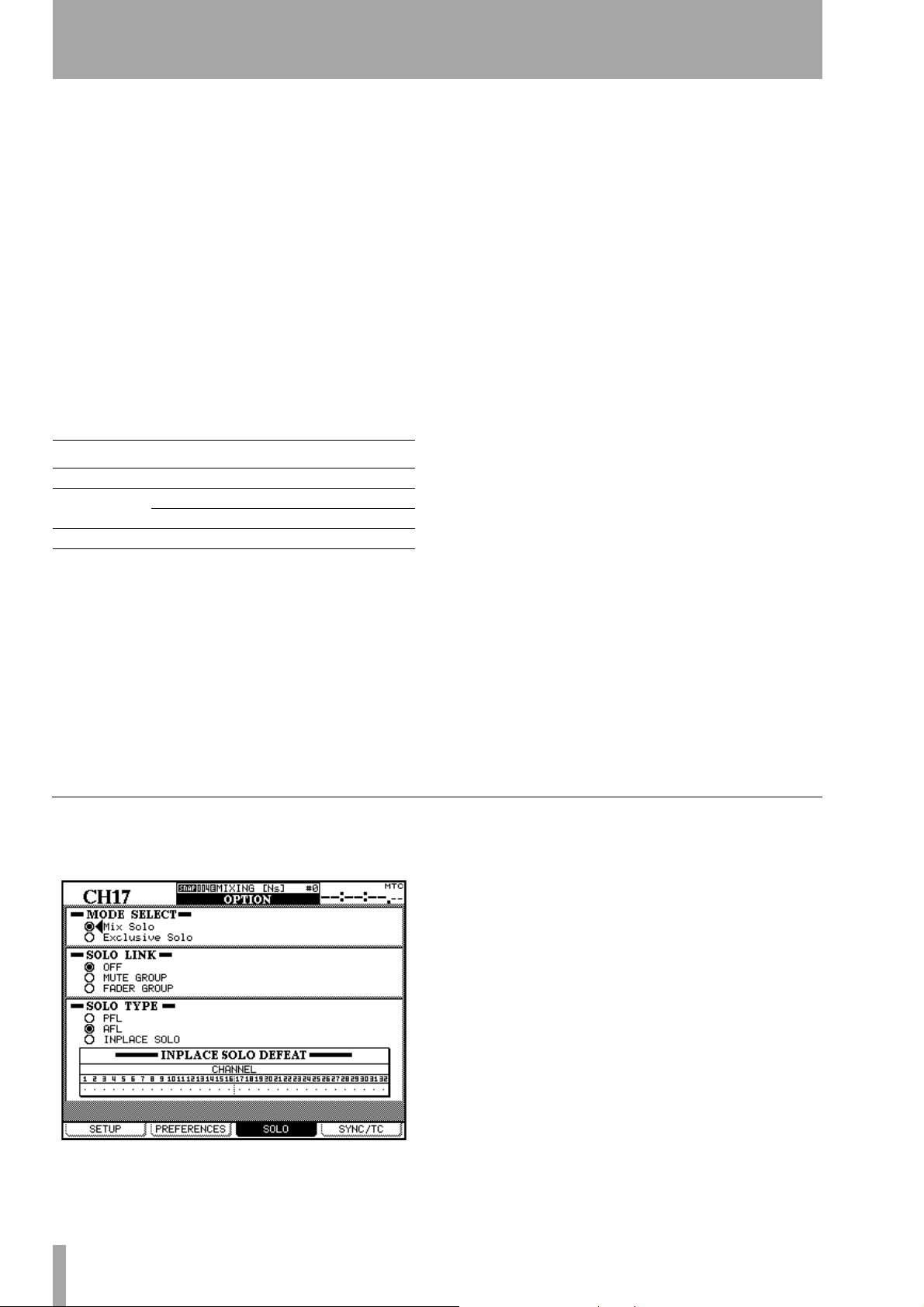
3 – System-wide options—OPTION screen
For example, if this option is active, and SEL 2 key is
lit with fader layer 1-16 active, fader layer 17-32 is
then selected,
then fader layer 1-16 is then re-selected,
SEL key 3 (channel 19) is selected, and
SEL key 2
will be active.
If the option is not active, any
SEL key which is lit
remains lit when the fader layer is changed. For
example, if this option is not selected, and
SEL key 2
is lit with fader layer 1-16 active, and fader layer
17-24 is then selected,
SEL key 2 will still be lit (that
is, channel 18).
Meter Follows SEL key When this option is
checked, the meter layer automatically changes when
the appropriate
faders” on page 77). The modes are as follows:
Fader layer SEL keys Meter layer
CH 1–16 CH 1–16 CH 1–24
CH 17–32
MASTER Buss 1–8/Aux1–6/Stereo MASTER/CH 25–32
SEL key is pressed (see “Meters and
CH 17–24 CH 1–24
CH 25–32 MASTER/CH 25–32
FLASH Info. This on-screen button allows you to
see how many times the flash memory used for storing library entries, etc. has been used (written to).
Moving the cursor to this on-screen button and pressing
ENTER brings up a pop-up panel showing the
number of times that the flash memory locations
have been used. Pressing
ENTER again allows you to
view the automation memory area usage. Dismiss
this pop-up by pressing
ENTER once more.
If any flash memory location has been written to too
many times in the life of the unit, a popup message
will automatically appear to alert you of this fact.
You should then contact your TASCAM dealer for
service.
Version Info. For service, etc. it is useful to know
the software version numbers of the different components. Moving the cursor to this on-screen button and
pressing
software version numbers of the different components (including the internal effector units). Press
ENTER to dismiss this panel.
ENTER brings up a pop-up panel with the
Automation fader OFF When this option is
active (checked), in automation mode, when the
automated mix is being read (played back), the faders
do not move.
Cursor follows EQ Band Key When the
option is enabled and modules are being edited, and
any of the EQ band keys (
LOW) is pressed, the box cursor surrounding the
HI, HI MID, LOW MID or
active on-screen controls will move to highlight the
active band.
SOLO
The solo modes on the DM-24 can be set up in a
number of different ways using this screen:
Battery Check This is a “read-only” display. It
shows the current voltage and the status of the
DM-24’s internal battery.
If the battery voltage falls below a certain level, or is
reported as being above a certain level, this display
blinks, and the screen shows
Can’t Save System Data,
together with the out-of-range voltage.
Consult your TASCAM distributor if you see this
message.
MODE SELECT Either Mix Solo or Exclusive Solo
can be selected here. The
number of channels (that is, all whose
are lit in solo mode) to have their outputs added
together to the solo mix. The
allows one channel (the one whose
pressed last) to be soloed at one time.
Mix Solo mode allows a
MUTE keys
Exclusive Solo mode only
MUTE key was
SOLO LINK This option allows the fader and mute
groups to be used with the solo function. This is
explained more fully in the solo part of the section
describing monitoring (see “SOLO LINK” on
page 75). Briefly, if one of the group options (
or FADER GROUP) is enabled, selecting a group
GROUP
master module solos or unsolos the whole of the
group. If a group slave module is selected, the solo
status of only that slave module is affected.
MUTE
22 TASCAM DM-24 Reference Manual
Page 23
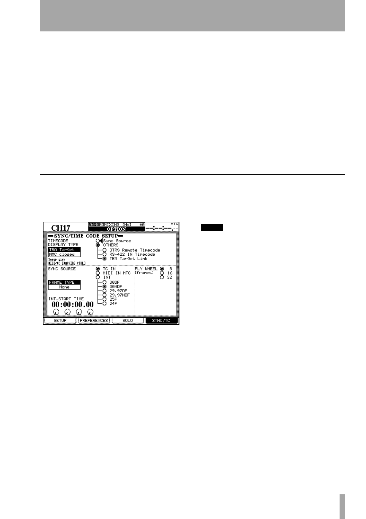
3 – System-wide options—OPTION screen
SOLO TYPE There are three options that may be
selected here:
post-fader listen) and
explained in more detail in the solo section, but
briefly; the
the signal before it is sent through the panpot and
fader. The stereo outputs are unaffected (soloing is
only done through the
puts) An AFL selection will output the post-fader
signal from the selected channels through the monitoring system. By contrast, soloing a channel in
Inplace Solo mode monitors the soloed signal(s) via
the stereo outputs while all the other signals are cut
from the stereo outputs.
PFL (pre-fader listen), AFL (after- or
INPLACE SOLO. Again, these are
PFL option provides a way of listening to
CR and STUDIO monitor out-
SYNC/TC
The following settings affect the timecode and synchronization settings (as can be selected for display
on the top right of the screen, used for automation
purposes as well as for location, etc.):
INPLACE SOLO DEFEAT This option is a defeat
option to prevent channels selected in this way from
being muted when other channels are soloed. It can
be used with a pair of effect returns, for instance, so
that these effect returns will always be added in the
inplace mix, together with those other channels
selected for inplace soloing. Inplace soloing will output the soloed channel(s) from the stereo outputs, and
cut all other channels. Use the cursor keys (or channel
SEL key) to highlight a channel, and the ENTER
key to change the status of the INPLACE SOLO DEFEAT
setting.
Alternatively, use the
direct selection and de-selection of the channels (use
ENTER to make the setting).
at the top right of the DM-24 display (above the timecode value). If timecode is selected as the timing
source on the DTRS unit,
of the display.
SEL keys of the modules for
TC is shown on the top right
The screen is split into two parts: the top part allows
the selection of a timecode source for display. This
displayed timecode may be the source used for automation synchronization (
source of timecode (
Sync Source is selected, the source selected in the
If
Sync Source) or another
OTHERS).
lower part of the screen to determine the automation
synchronization source is displayed.
The following options are available for the display of
incoming timecode:
DTRS Remote Timecode This is the timecode
embedded in the REMOTE/SYNC output from a
DTRS unit. The actual format and the relationship of
this to the ABS time on the DTRS unit depends on
the setup of the DTRS unit. If the ABS time is used
as the timing source on the DTRS unit,
ABS is shown
NOTE
A DTRS unit connected to the DM-24 through a card
inserted in slot 1 or 2 cannot be used as a timecode display source in this way.
RS-422 IN Timecode This refers to any timecode
received through the RS-422. If this option is
selected,
TC is shown on the top right of the DM-24
display.
TRA Target link This refers to the timecode from
the currently selected transport target (as set up in the
MIDI/MC settings
TC or DTRS is shown on the top right of the
Either
screen if the transport target is a DTRS unit (as
explained above),
the transport target is a closed MMC loop, and
ABS if an ADAT is selected, MTC if
INT if
the internal generator is selected as the transport target.
If the transport target is a MMC closed loop device,
MMC Closed) is highlighted on screen.
this (
Automation synchronization source
Choose from the following options to select the automation synchronization timecode source:
TC IN This refers to the analog linear timecode sig-
nal received at the
selected,
TC is shown on the top right of the DM-24
display.
TC IN jack. If this option is
TASCAM DM-24 Reference Manual 23
Page 24
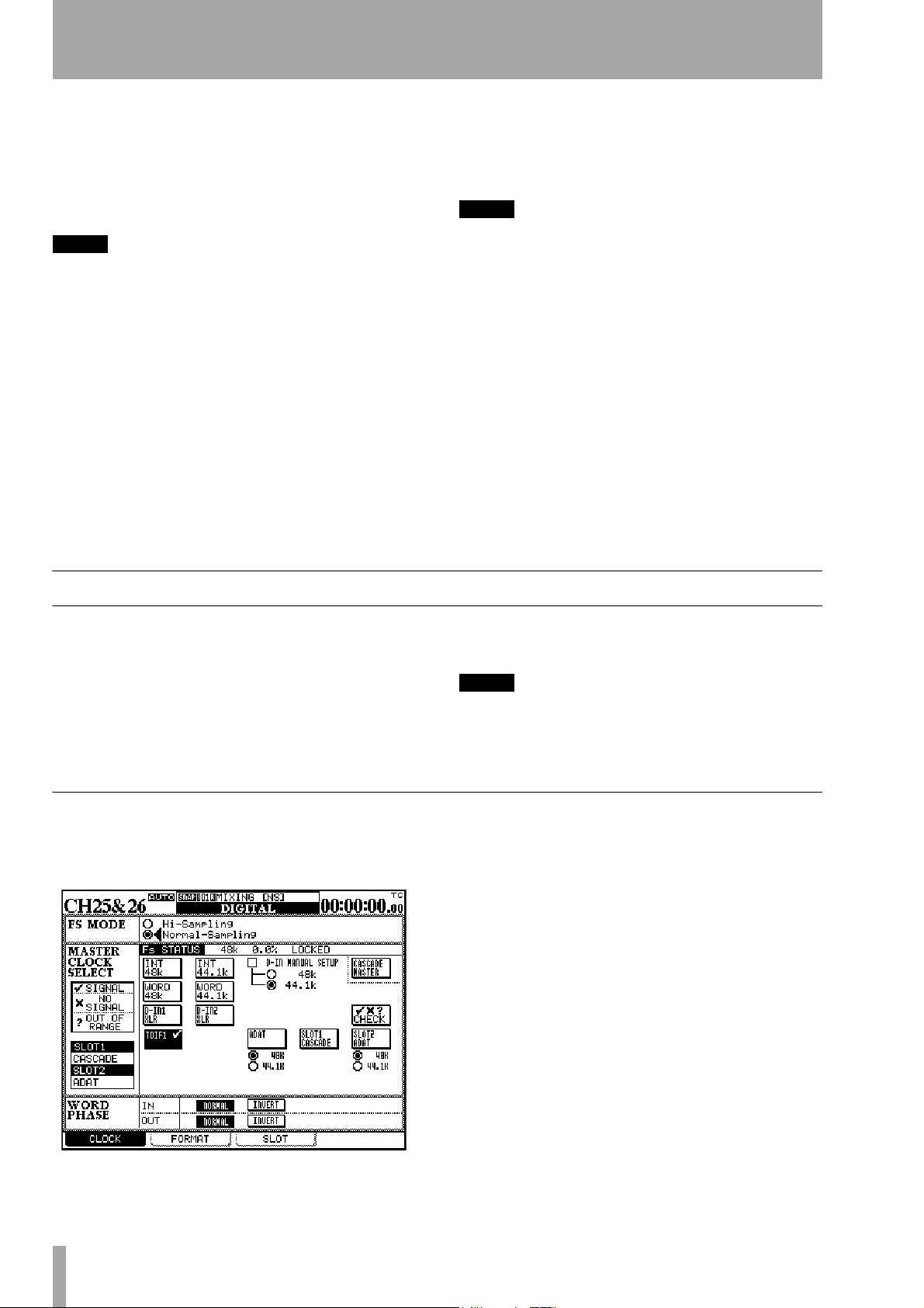
3 – System-wide options—DIGITAL screens
MIDI IN MTC This refers to any MIDI Timecode
received at the
MTC is shown on the top right of the DM-24 display.
MIDI IN jack. If this option is selected,
INT. This refers to the DM-24’s own internal (MIDI
Timecode) generator.
NOTE
The internal timecode generator is not functional in this
release of the DM-24 software. It will be implemented
in a future release, and appropriate documentation
concerning its use will be provided at that time.
If the internal generator is chosen, the frame type can
be selected from the following list:
drop-frame),
fps drop-frame),
(25 fps) and
30NDF (30 fps non-drop), 29.97DF (29.97
29.97NDF (29.97 fps non-drop), 25
24 (24fps). If this option is selected, INT
is shown on the top right of the DM-24 display.
If the internal frame type is changed, then an automatic calculation is performed to convert the old
frame type as accurately as possible to the new frame
rate. For instance, if the frame type is 24 fps and the
30DF (30 fps
current frame position is set to 12 (that is, halfway
through a second), if the frame type is changed to 30
fps the frame position will be set to 15 (again, halfway through a second).
NOTE
When external timecode sources are used, the frame
type is automatically recognized.
INT. START TIME If the internal generator is
selected as the timecode source, then the PODs are
used to set the generator start time. Move the cursor
so that the time is surrounded by an on-screen box,
and then use the four PODs to set the hours, minutes,
seconds and frames of the generator start time.
FLY WHEEL (frames) If an external timecode
source is selected, then it is possible to compensate
for loss of incoming signal, allowing the DM-24 to
“flywheel” for a set number of frames before it
reports the loss of incoming timecode. The values
available here are 8, 16 and 32 frames (the length of a
frame depends on the frame type being received).
DIGITAL screens
The DIGITAL screens contain a number of different
parameters affecting the digital audio operation of
the DM-24.
There are three screens: the
digital clock source is selected, the
which provides facilities for controlling the format of
digital data transmitted from and received by the
CLOCK settings
This screen allows the viewing and selection of digital audio clocks from devices connected to the
DM-24.
CLOCK screen, where the
FORMAT screen,
DM-24, and the
SLOT screen, to control any optional
cards fitted in the slots.
NOTE
There should be one, and only one, word clock source in
a digital audio setup. Multiple word clocks in a setup
may result in noise which can damage monitoring
equipment (speakers and amplifiers).
Use the cursor keys or dial to move around the
screen, and the
ENTER key to make selections.
Depending on the current assignments, the screen
may change a little from that shown here. For example, if ADAT has not been selected as a return source,
then it will not be shown in the appropriate position.
If slot cards are not fitted, they will not appear on this
screen, but if they are fitted, the
SLOT fields to the left
of the screen are filled, and show the slot cards currently fitted.
24 TASCAM DM-24 Reference Manual
The condition of a master clock status is shown using
symbols.
If the right clock is not available, or if the clock is out
of the permissible limits, an appropriate symbol
(cross or question mark) is shown.
Page 25
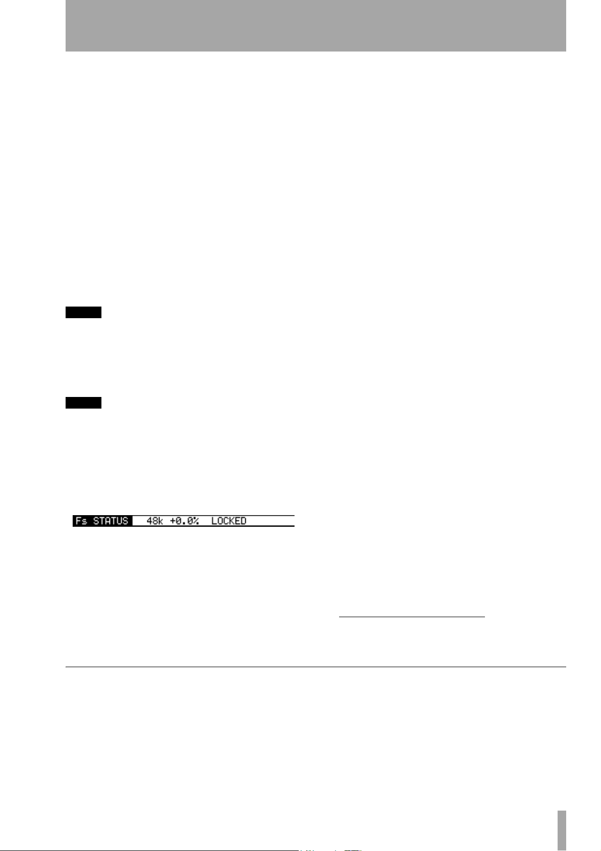
3 – System-wide options—DIGITAL screens
A popup appears with an unlocked indication and an
error message. If this happens, correct the clock
source, and press the
ENTER key to dismiss the
popup.
When a clock source is selected, the clock indicators
to the left of the console change to show the current
clock frequency and the
EXT CLOCK indicator lights
if an external clock has been selected as the clock
source.
High sampling frequency To select high sam-
pling frequency mode, select
ENTER.
When the DM-24 changes to high sampling frequency, a popup message is shown on screen, telling
you to turn off the DM-24 and turn it on again, to
enter high sampling frequency mode.
NOTE
Remember to turn down the monitor value, etc. to
avoid “thumps” which may damage equipment when
turning the DM-24 on and off.
Hi-Sampling, and press
D-IN MANUAL SETUP A manual selection may
be made in the case of one of the digital inputs (
being selected as a clock source with sampling frequency conversion. Select the appropriate destination
frequency here.
Whether the RCA or XLR connector is used as the
clock source is selected in the
I/O screens (“Digital
inputs” on page 39), not here.
D-IN)
WORD SYNC IN Since the frequency information
of any signal received at the
nector is not used by the DM-24, if this source is to
be selected as the word sync source for the DM-24,
the sampling frequency must be explicitly selected.
WORD SYNC IN con-
TDIF interfaces In the case of the TDIF-1 inter-
faces card), the device attached to the card source is
shown as either a
OTHER (another type of recorder connected through
the TDIF-1 interface). If the indicator shows DA88,
then I/O data is truncated to 16 bits, otherwise I/O is
carried out at 24 bits.
DA-88 (DA-88 DTRS recorder) or
The clock source screen changes in the case of high
sampling frequency being selected.
NOTE
Many other display screens will change if high sampling
frequency is selected. These differences are described in
a separate chapter (“High sampling frequency” on
page 112).
Fs Status This shows the current sampling fre-
quency status (base frequency, deviation from the
nominal value, and the locked/unlocked status).
Select the appropriate clock source. In the case of the
internal clocks, the frequency may be chosen as
either 44.1kHz or 48kHz. In most other cases, the
frequency is pre-determined.
There are one or two other points to be borne in mind
when making these settings.
ADAT In the case of an ADAT “lightpipe” interface
card, the
clock master, is always selected.
INT setting, allowing the ADAT to act as the
AES3 In the case of an AES/EBU interface card,
there are four different sources (the four AES/EBU
1
inputs
) which may be selected as the word clock
source for the DM-24.
CASCADE MASTER If the DM-24 has been set
up as a cascade slave (using the
screen), then this cascade master option is automatically selected, and this setting cannot be changed (the
master is free, of course, to accept its clock from anywhere).
DIGITAL SLOT
Word phase The phase of the word sync signal
can be inverted independently for input and output
relative to normal. Use the phase correction facilities
to match word clocks from different equipment.
1. This changes to two inputs when high frequency sampling is selected.
Checking the clock sources
To give details of all possible sources, move the cursor to the on-screen
A popup message appears. Use the
continue with the check (cancel using any of the cursor keys).
CHECK button, and press ENTER.
ENTER key to
The DM-24 mutes, and a panel appears with details
of all possible clock sources. Press
ENTER once
again to dismiss this panel.
TASCAM DM-24 Reference Manual 25
Page 26
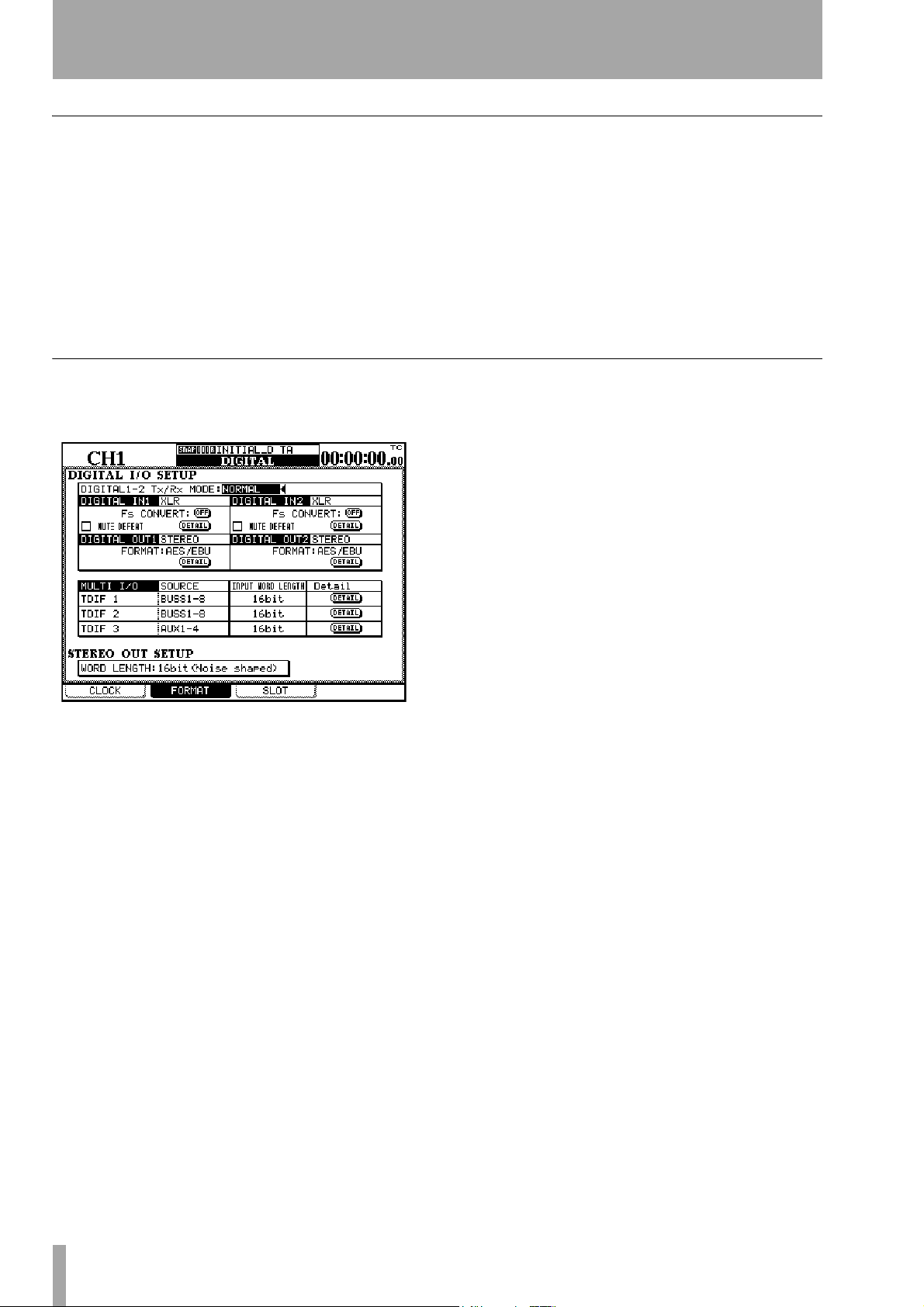
3 – System-wide options—DIGITAL screens
Out of range clock signals
When setting the clock, the sampling frequency
received can be ±6% of the stated nominal value.
When in use, the frequency can be ±7% of the stated
value. This allows a digital device which has a
varispeed feature to be used as the word clock source
for the DM-24.
If the selected clock source goes out of range, the
DM-24 mutes, the currently-selected clock indicator
flashes, and a message appears on the display.
The FORMAT screen
This screen allows you to see and work with the digital audio inputs and outputs connected to the DM-24.
The DM-24 reports the out-of-range clock frequency
at a range of ±9.9% relative to the stated frequency,
but mutes at 7.0% or over.
Press the
change to the
condition (by selecting another clock source, or by
re-selecting the clock if it has come back into range).
ENTER key to dismiss the popup message,
CLOCK screen, and correct the error
Other digital input parameters At normal
base sampling frequencies, the DM-24 is capable of
performing sampling frequency conversion on the
incoming data. This can be turned on or off individually using the on-screen
MUTE DEFEAT checkbox allows the DM-24 to
The
ignore a status bit in some implementations of digital
audio, which are otherwise satisfactory. If this is
unchecked, when this audio is received, the input
may be muted and the following messages may be
displayed on screen:
bit 1=1 of the channel status) or
(byte 0, bit5=1).
Fs CONVERT buttons.
Not Audio data Digital In1 (byte 0,
Source Fs unlocked
The first part of this screen affects the digital inputs.
Note that the I/O screen is used to determine whether
the XLR connector or RCA pin jack is used for each
of these inputs.
Type of DIGITAL IN connection Typically,
these connectors will be used for base frequency digital audio (44.1 k or 48 k). This is shown as
on the display. However, if the DM-24 is in high
sampling frequency mode, these inputs may be used
for high sampling frequency inputs. There are two
ways in which they can be used for high sampling
frequency;
used to transmit one channel of high sampling frequency audio, hence two lines are needed for a stereo
pair) and
at twice the usual speed, where one AES/EBU cable
is used to transmit a pair of high sampling frequency
signals at high speed.
Use the cursor, dial and
If the DM-24 is set to an incompatible sampling frequency, a popup message appears.
DUAL-LINE (where one AES/EBU cable is
HIGH-SPEED where the audio is transmitted
ENTER key to set this value.
NORMAL
Details of the digital audio data can be obtained from
a popup produced by pressing the
Such information includes the format, type, emphasis
status, etc.
DETAIL button.
Digital output The assignments for the two digi-
tal outputs are made using the I/O screen. The format
can be changed between AES/EBU and SPDIF (the
SPDIF option is meaningful at base sampling frequen-
cies only) and details of the data can be obtained
from a popup produced by pressing the
ton. Such information includes the format, contents,
emphasis status, word length, etc.
DETAIL but-
Multi I/O settings These assignments are made
in the I/O screen, and cannot be changed. However,
the word length for each of the TDIF groups can be
set (either
viewed (
mode, sampling frequency, word length and emphasis status, etc.
16bit, 20bit or 24bit) and the details can be
DETAIL button). These details include TX/RX
Stereo out setup This allows the choice of the
word length output from the stereo out as being
either 24-bit data, 20-bit with noise shaping, or 16-bit
with noise shaping.
26 TASCAM DM-24 Reference Manual
Page 27
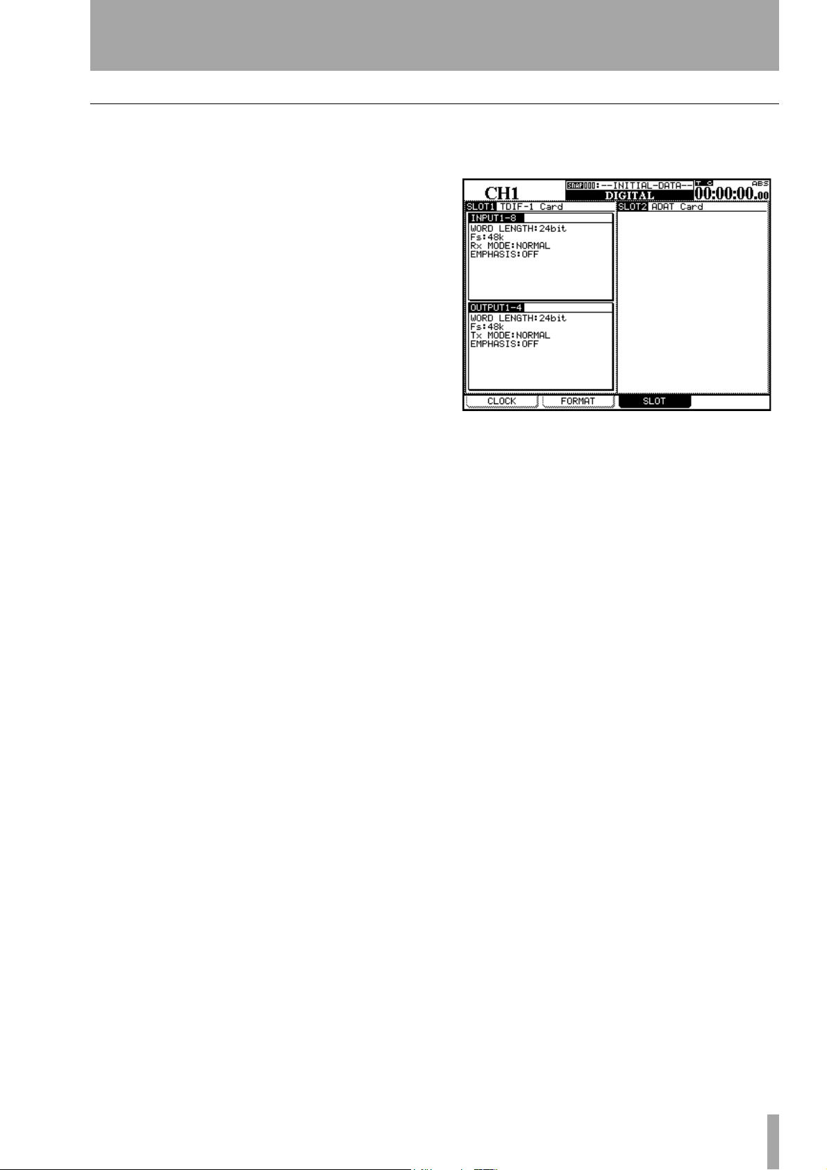
SLOT screen
3 – System-wide options—DIGITAL screens
On the slot screen, the different optional interface
cards that can be fitted to the DM-24 are automatically detected and the options can be set. These are
described separately in “Options” on page 118.
If slot cards have been fitted, they are shown on this
screen, as in the example below.
TASCAM DM-24 Reference Manual 27
Page 28
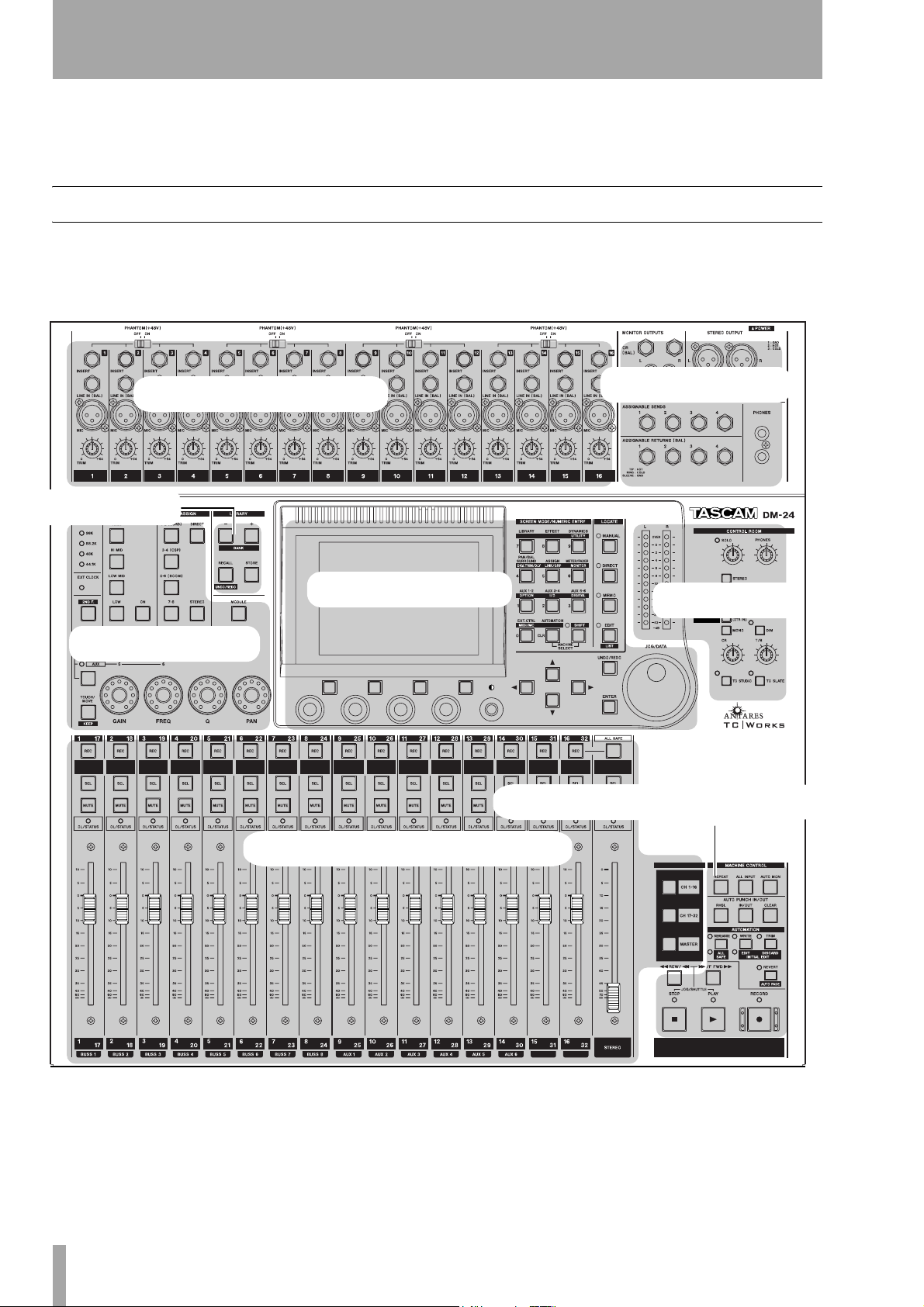
4 – Parts of the DM-24
This section is divided into what we hope is a functional and logical order to help locate and use the
controls.
Top surface
The top surface of the DM-24 may be conveniently
divided into the following sections:
Analog module inputs
Library section
This section is not a complete guide to the functions
of the DM-24—treat it more as a “road-map” than a
guidebook.
Other analog I/O
Module control
Parameter control
Transport and automation control
Module faders and selection, etc.
Monitoring
28 TASCAM DM-24 Reference Manual
Page 29
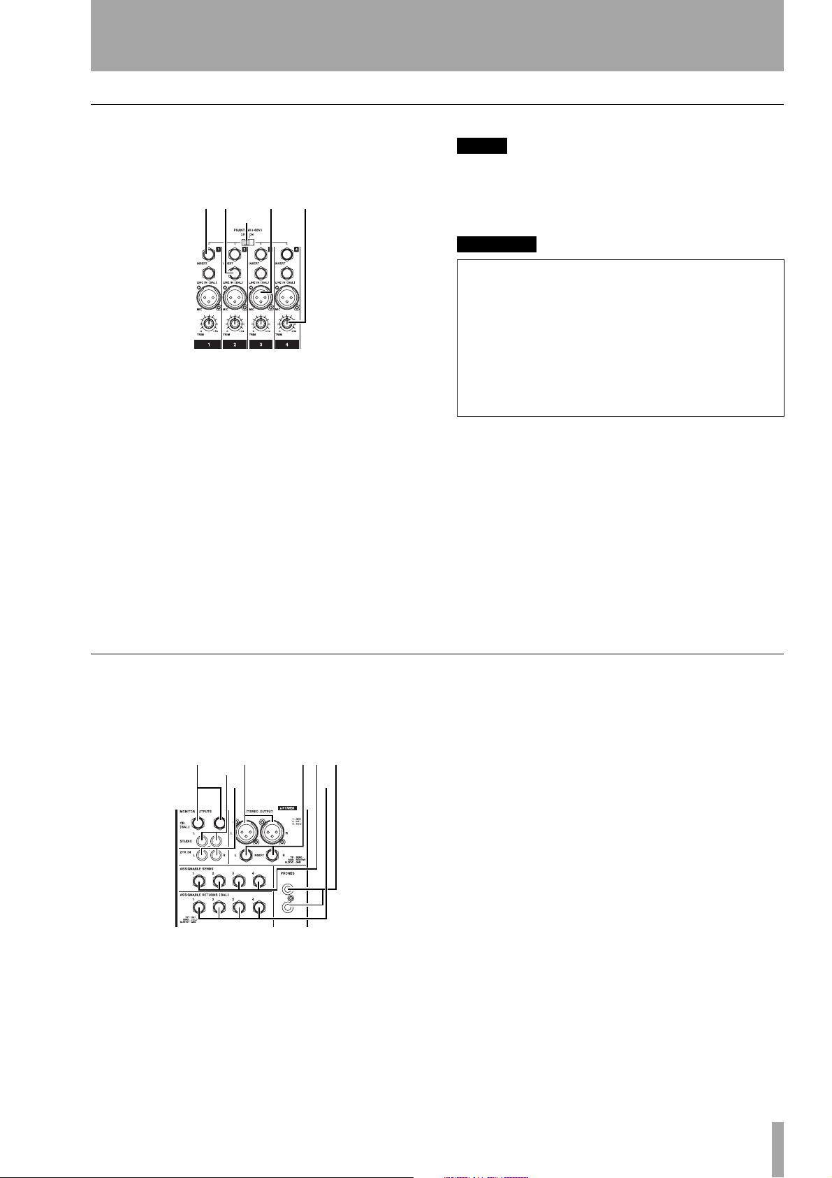
Analog module inputs
4 – Parts of the DM-24—Top surface
These inputs typically feed the first sixteen input
channels, but may be assigned in other ways as
explained in “Setting up the I/O” on page 36.
12 3 4
5
1 INSERT These TRS 1/4” connectors are used
to provide a postthe return (–2dBu) occurring just pre-AD convertor.
TRIM insert (send at –2dBu), and
2 LINE IN (BAL) These balanced 1/4” jacks
accept analog inputs at a nominal +4dBu input level,
adjustable with the
TRIM controls.
3 MIC These XLR connectors accept analog
inputs for balanced microphones. Phantom power is
available (switchable in groups of 4 inputs).
The input level is adjustable with the
TRIM controls.
NOTE
There is no switch to allow a choice between the
and the
not be made to both inputs of a channel simultaneously.
LINE
inputs. Accordingly, connections should
WARNING
Connection of microphone cables and microphones:
to prevent hazard or damage, ensure that only
microphone cables and microphones designed to the
IEC 268-15A standard are connected.
Connexions des microphones et de leurs câbles: pour
éviter tout endommagement, s’assurer de brancher
uniquement des microphones et des câbles de microphones conçus selon la norme IEC 268-15A.
MIC
4 TRIM These controls allow the input levels
from the
range of 56dB.
Turning these controls clockwise increases the level
of the signal fed to the channel AD convertors.
MIC and LINE inputs to be adjusted over a
5 PHANTOM (+48V) These switches allow
+48V phantom power to be provided to the
channel inputs. These switches are arranged so that
one switch controls the phantom power for four input
channels (1 through 4, 5 through 8, 9 through 12, and
13 through 16).
MIC
Other analog I/O
These inputs and outputs provide analog feeds to
monitoring systems, etc.a balanced pair of stereo
master outputs and an insert loop for these outputs.
8
7
06
qe
9w
There are also four assignable sends and returns, as
explained in “Setting up the I/O” on page 36.
6 MONITOR OUTPUTS [CR (BAL)] These
1/4” balanced analog outputs are used to provide
monitoring signals to the control room as selected
using the monitor select switches (+4dBu nominal
level).
7 STEREO OUTPUT This pair of balanced
XLR connectors provides the analog stereo out signal
at +4dBu.
8 MONITOR OUTPUTS [STUDIO] These
unbalanced RCA connectors provide unbalanced signals to the studio at a nominal output level of
–10dBV.
9 2-TR IN These two RCA unbalanced inputs
are typically used for monitoring the replay from an
analog mastering device at a nominal input level of
–10dBV.
A STEREO OUTPUT [INSERT] These 1/4”
TRS connectors provide insert facilities for the
STEREO OUTPUTs. The send (level –2dBu) is post
DA convertor and the return (level –2dBu) is immediately before outputs.
TASCAM DM-24 Reference Manual 29
Page 30
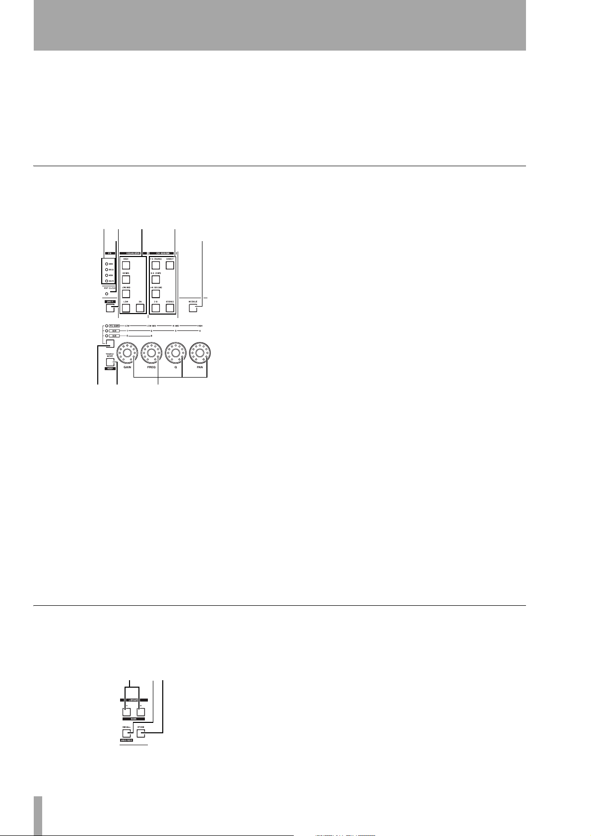
4 – Parts of the DM-24—Top surface
B ASSIGNABLE SENDS These balanced
1/4” jacks (–2dBu) are used either as insert sends for
the input channels or as aux sends (see “Setting up
the I/O” on page 36).
C ASSIGNABLE RETURNS (BAL) These
quasi-balanced returns (–2dBu) are either used as
Module control section
This section is chiefly used for the control of the
most commonly-used module parameters:
rt y u
io
aux returns or as insert returns for the input channels
(see “Setting up the I/O” on page 36).
D PHONES These two stereo 1/4” jacks provide
headphone outputs.
BUSS 1-2, BUSS 3-4, BUSS 5-6 and BUSS 7-8)
ses (
or to the stereo outputs (
(
DIRECT).
The legends in parentheses on the first three buss
keys refer to surround assignments if a surround
mode has been selected.
STEREO) or to direct output
I EXT CLOCK indicator If this indicator is
lit, the DM-24 is referenced to externals word sync.
If unlit, the DM-24 is acting as the master word sync
source for the system. If flashing, the clock source is
not connected, or is not otherwise available for use
by the DM-24.
pa s
E FS indicators These indicators show the
current sampling frequency used by the system.
F 2ND F. (MOVE) key This key is mainly
used in conjunction with the automation (purple)
keys to access the secondary functions of these keys.
G EQUALIZER keys As explained in “Rotary
encoders (ring LEDs)” on page 15, four of these keys
(
HIGH, HI MID, LOW MID, LOW) are used to select
the frequency band of the active module which will
be affected by the rotary encoders. The
the EQ on and off for the selected module.
ON key turns
H CH ASSIGN keys These keys are used to
assign the selected module to the pairs of output bus-
Library section
These keys are used for the storage and recall of
commonly-used parameters in snapshots, EQ settings, effects and so on.
dfg
J MODULE key Pressing this key brings up
the module editing screen, allowing the different
parameters of a module to be viewed and edited.
K Encoder function select key and
indicators Successive presses of this key light, in
order: no indicator,
AUX (5 and 6), as explained in “Rotary encoders
(ring LEDs)” on page 15. The indicators show the
current function of the encoders.
EQ GAIN, AUX (1 through 4) and
L TOUCH/MOVE [KEEP] key This key is
used in conjunction with the automation software, as
explained in the automation guide.
M Rotary encoders These are used to set
parameters as explained in “Rotary encoders (ring
LEDs)” on page 15.
N LIBRARY + and – [BANK] keys These
are used to change the selected active library entry
(usually shown at the top of the screen).
O RECALL [UNDO/REDO] key The
RECALL key is used to recall the settings of stored in
the currently-select active library entry. It can also be
used for comparison between the new and previous
settings.
30 TASCAM DM-24 Reference Manual
Page 31

P STORE key This key stores the current set-
tings to the currently-selected library entry.
Parameter control section
4 – Parts of the DM-24—Top surface
This section is used to control the different parameters and to navigate through the different options
available on the DM-24
hj kl;z x
v
b
c
n
Q LCD display This backlit display shows the
parameters and values that can be adjusted, as well as
popup status and error messages.
R Soft keys These four keys are used to select
options and sub-screens shown at the bottom of the
display (“Soft keys” on page 15).
S PODs These encoders are used to set values
highlighted on the screen with the cursor (“PODs” on
page 13).
Number Unshifted function Shifted function
1
2
3
4
5
6
7
8
9
Aux 1 and 2 sends
(
AUX 1-2)
Aux 3 and 4 sends
AUX 3-4)
(
Aux 5 and 6 sends
AUX 5-6)
(
Pan and balance (surround
settings if surround
selected) (
SURROUND
Channel-to-buss assignment (
On-screen meters and fader
positioning (
FADER
Library settings and selection (
Effect settings and editing
EFFECT)
(
Dynamics processor settings (
PA N/ BA L
)
ASSIGN)
METER/
)
LIBRARY)
GATE/DYN)
System options (
Input and output assignment (I/O)
System setup options
(SETUP)
Digital trim and channel
TRIM/DLY)
delay (
Stereo linking and fader/
mute grouping (LINK/
GRP
)
Monitoring settings and
options (
—
—
Various system utilities
(UTILITY)
OPTION)
MONITOR)
W SHIFT key and indicator This is a
“smart” key. Press and release it briefly to light the
indicator. Press and release it briefly again to turn off
the indicator.
T Display contrast Use this control to set the
most convenient viewing angle for the display.
U Cursor keys These keys are used to move
the on-screen cursor to highlight the parameters to be
edited with the PODs or the data dial.
V Number and predefined function
keys These keys are used to access the setting
screens where global parameters may be set up and
for changing between sub-screens.
SHIFT key is also used to provide a secondary
The
function for most of these keys, bringing up screens
which probably will not be used so frequently.
In some location modes, these keys are used to enter
numeric values directly:
Number Unshifted function Shifted function
CLR AUTOMATION (auto-
mation) control
0
External device control
EXT. CTRL)
(
—
MIDI and machine control
parameters (MIDI/MC)
Press and hold the key for more than about half a second to light the indicator for only as long as the key is
held down (when the key is released, the indicator
goes out).
When the indicator is lit, the predefined function
keys will then perform their secondary shifted function (as marked on the lower label above the key).
X LOCATE keys and indicators These
keys are used to set the way in which location of the
currently-selected machine transport is controlled.
If any of these indicators is lit, the predefined function keys act as number keys (as explained in “Location memories” on page 85).
Y AUTOMATION UNDO key This key is
used with the automation system to undo changes
made to automated mixes.
Z JOG/DATA dial This dial is used for setting
on-screen parameter values, etc. When the DM-24 is
controlling the transport of a remote device, it may
be used to perform a jog function.
TASCAM DM-24 Reference Manual 31
Page 32

4 – Parts of the DM-24—Top surface
a ENTER key Use this key to confirm entries
and to answer “yes” to questions (the cursor keys are
usually used to cancel or answer “no”).
Monitoring section
This section is used to control what is heard from the
control room and the studio monitoring systems.
Since many of the choices here are “soft” choices
(that is, determined by the software), the full explanation of these keys and indicators is provided in a
separate section (“Monitoring” on page 73).
m,./!@
# $%^ &
b Meters These meters show the level of the
currently-monitored signal.
c SOLO control and indicator When the
indicator is lit, soloing is enabled and a channel has
been selected for soloing. The level of the soloed signal is controlled by this knob.
f Talkback microphone This integral
microphone can be used for studio talkback or slate
output.
g DIM key and indicator This “smart” key
works in the same way as the
When on, the control room outputs are attenuated
(the amount is set using the monitor screen).
STUDIO key above.
h MONO This outputs the selected signal in
mono to the control room monitors and phones.
i STUDIO key and indicator This “smart”
key latches on when pushed and released within a
second, and is switched off by pushing it again in the
same way. If pushed and held down for more than a
second it is non-latching, that is, it turns off when
released.
When on, the control room outputs are attenuated,
and the talkback microphone signal is routed to the
studio outputs.
j CR volume control This control adjusts
the level of the signal selected with the selection keys
and sent to the control room outputs and
outputs.
PHONES
d PHONES control This control regulates the
level of the signal sent to the phones outputs.
e Monitor selection keys These keys are
used to select the signal sent to the control room
monitor outputs (and the phones outputs).
STEREO key routes the stereo output signal to
The
the monitor outputs. The
keys route the signals selected in the monitor screen
to the monitor outputs.
SEL 1, SEL 2 and SEL 3
k TO SLATE key and indicator This
“smart” key works in the same way as the
key above.
When on, the control room outputs are attenuated
and the talkback microphone signal is routed to the
eight output busses, the stereo buss and the six aux
busses.
STUDIO
l T/B volume control This control adjusts
the level of the signal from the talkback microphone,
fed to the selected outputs (slate or studio).
32 TASCAM DM-24 Reference Manual
Page 33

Module faders and selection, etc.
4 – Parts of the DM-24—Top surface
The module faders are arranged in layers (see “Fader
layers” on page 18). Accordingly, the 16 module faders are used to control all 32 inputs, the six aux sends
and the output buss sends as shown on the preprinted labels above and below each channel strip.
*
(
)
Q
W
Note that a wipe-off surface is provided (below the
REC keys) for you to write in soft pencil the func-
tions of the channels (equipment connected to the
DM-24, etc.).
E
R
T
Y
m REC key These keys, with integral indicator,
are used to set and show the recording status of tracks
of devices controlled by the DM-24.
n SEL keys These keys, with integral indica-
tors, are used to select the modules for editing operations, as well as for stereo linking and other editing
functions. The indicators light to show which module
has been selected.
o MUTE keys These keys, with integral indica-
tors, show the muting status of the modules. When
used with the solo modes, they give instant indication
of what module(s) are selected for soloing.
p OL/STATUS indicators These indicators
may be selected using software to show either overload to the input channels or the current status of the
channel when automation operations are being carried out. See “OL/STATUS LED TYPE” on page 20
for details of these settings.
q Module faders These 100mm motorized
faders are labeled from ∞ (full cut) to
0 position may be set to be equivalent to the appro-
priate full-scale value using software.
+10 (dB). The
r ALL SAFE key This key, with integral indi-
cator, is used to “safe” any tracks of recording
devices controlled by the DM-24.
s SOLO key This key, with integral indicator,
is used to enable the soloing function as selected in
“SOLO” on page 22.
t STEREO fader This fader does not change
function as the layers are changed, but controls the
level of the stereo outputs.
It is labeled from ∞ (full cut) to
0 (full scale).
u LAYER STATUS keys These keys (with
integral indicators), as explained in “Fader layers” on
page 18, change the function of the modules to provide access to the different fader layers.
Transport and automation control
UI O P
S
A
This controls in this section provide remote control
facilities for recording devices, etc. attached to the
DM-24.
v REPEAT key This key, with integral indica-
tor, is used to control repeat playback.
w ALL INPUT key Provides input monitoring
for all tracks on the selected unit(s).
x AUTO MON key Provides automated
switching between input and off-tape monitoring.
y AUTO PUNCH IN/OUT keys Typically
used with the DTRS family of recorders.
z Transport keys and indicators The
exact function of these keys (
PLAY and RECORD) and indicators depends on the
device currently selected for external control.
TASCAM DM-24 Reference Manual 33
REW, F FWD, STOP,
Page 34

4 – Parts of the DM-24—Rear panel
S Automation control keys and
indicators These keys (REHEARSE, WRITE,
TRIM and REVERT) are used to control the automa-
tion functions. These keys have other functions, as
selected by the
2ND F key (F).
Rear panel
The rear panel of the DM-24 houses the digital audio
and control connections.
1
56 7 8 9
NOTE
Although some of these keys have similar names to
other keys on the DM-24, note that their functions are
restricted to automation operations.
23 4
ABCDE
NOTE
Only use TASCAM-supplied and TASCAM-approved
cables when making digital audio and control connections to the DM-24. Though the cables and connectors
may resemble computer cables, they serve different
purposes, and meet a different set of specifications. The
use of cables other than TASCAM cables will at best
cause the equipment to work erratically, and at worst
cause damage to the equipment.
If the use of cables other than TASCAM cables causes or
results in damage, the warranty is voided.
1 TO METER This 25-pin ‘D’-sub connector is
used to connect the DM-24 and the optional MU-24/
DM meter unit.
2 ADAT [IN, OUT] Use these “lightpipe” con-
nectors to connect ADAT-compatible units to the
DM-24 with a Toslink-type optical cable. Each of
these connectors carries eight digital audio input or
outputs channels.
The input may be used as a clock source, and routed
to any of the three groups of eight input channels (1
through 8, 9 through 16, 17 through 24).
3 WORD SYNC [OUT/THRU, IN] and
switch
sync. The switch controls the behavior of the connectors (75Ω input impedance and switching between
OUT and THRU functions) as described here:
Position
Left
Center
Right
A
word sync signal received at the
means that the DM-24 originates a word sync signal
(and is therefore to be the word sync master for the
system).
These BNC connectors are used for word
Ω
IN
75
termination?
No Thru
No Out
Ye s O ut
THRU setting means that the connector echoes the
OUT/THRU
IN. An OUT setting
34 TASCAM DM-24 Reference Manual
Page 35

4 – Parts of the DM-24—Rear panel
4 TDIF [1, 2 3] These 25-pin ‘D’-sub connec-
tors are used for the connection of suitably-equipped
digital audio devices.
At the base rates of 44.1k and 48k, each connector
carries eight channels of input and eight of output.
These numbers are halved when dual-frequency sampling frequencies (88.2k and 96k) are used.
These may be routed to any of the three groups of
eight channels capable of accepting return signals (1
through 8, 9 through 16, 17 through 24).
TDIF 1 only may be selected as the clock source for
the system.
5 MIDI IN, OUT and THRU These three 5-
pin DIN connectors correspond to the MIDI standard
(
MIDI IN receives MIDI data, MIDI OUT outputs
MIDI data originated by the DM-24, and
echoes data received at
The MIDI is used for MIDI Timecode, Program
Change and Control Change messages, as well as for
MIDI System Exclusive bulk data dumps, etc. The
details of these are all given in the section on MIDI
(“MIDI” on page 95).
MIDI IN).
MIDI THRU
6 EXT SW This 1/4” jack is used to connect a
footswitch (for example, the TASCAM RC-30P),
which is selectable through software to provide a
variety of functions.
7 TIME CODE This unbalanced RCA connec-
tor accepts SMPTE/EBU analog timecode.
8 DTRS REMOTE CONTROL This 15-pin
‘D’-sub connector connects to the first unit in a chain
of DTRS recorders, allowing the DM-24 to remotely
control the recorders.
9 SLOT [1 and 2] These expansion slots allow
the fitting of optional cards, such as a cascade card,
AES/EBU interfaces, additional “lightpipe” interfaces, or additional AD-DA conversion interfaces.
Consult your TASCAM dealer for availability of
such cards, and the documentation supplied with the
cards for details of how to fit and use them.
A POWER SWITCH and IN Use this push-
on/push-off switch to switch the power to the DM-
24. Use only the provided power cord to connect the
DM-24 to the AC supply, ensuring that the voltage of
the supply matches the voltage requirements as given
on the rear panel of the DM-24. If you are in any
doubt, consult a qualified electrician.
NOTE
The equipment draws nominal non-operating power
from the AC outlet with its
position.
POWER
switch in the OFF
B DIGITAL OUTPUT 1 and 2 Each of these
outputs has two connectors: an XLR-type and an
RCA connector. The format of the output is determined by software.
The function of these connectors (master stereo output, stereo aux send, etc.) is also determined by software settings.
C DIGITAL INPUT 1 and 2 Each of these
inputs has two connectors: an XLR-type and an RCA
connector. Only one connector at a time can be used
for the input (selected by software).
The routing of these connectors is also determined by
software settings.
D GPI This 9-pin ‘D’-sub connector is a General
Purpose Interface, used for remote control of devices
attached to the DM-24.
E RS-422 This 9-pin ‘D’-sub connector is a
remote control interface, to the RS-422 standard,
allowing remote control of devices attached to the
DM-24.
TASCAM DM-24 Reference Manual 35
Page 36

5 – Setting up the I/O
Because the DM-24 is a “soft” digital mixing console, there are few of the hard-wired assignments that
you find on an analog console.
In addition, the DM-24 includes an internal patchbay,
which allows routing and splitting of signals within
the console, providing a high degree of flexibility,
and easy re-configuration when the requirements
within a project change.
These routing and configuration settings can be
stored in snapshot settings, allowing easy switching
between the commonly-used routing patterns (for
example, tracking, overdubbing and mixdown).
Signal sources
The DM-24 defines channel signal sources as inputs
and returns, as explained here.
In the I/O assignment screens, each channel from 1
through 24 has two different sources—input and
return—available (channels 25 to 32 have only one
source—input—available):
The library facilities also allow the retention of I/O
patches, etc. between snapshots, so that the I/O settings are not always overwritten by the recalled snapshot. See “Protecting snapshot settings” on page 102
for full details.
NOTE
This section deals only with the assignments in normal
sampling frequency modes (either 44.1k or 48k). If the
DM-24 is to be used in high sampling-frequency mode,
the screens and the options are a little different. See
“High sampling frequency” on page 112 for details.
ADAT connector The single “lightpipe” ADAT
input connector carries eight channels of digital
audio input.
The eight audio channels received through this connector may be assigned to any of the console channels numbered 1 through 24.
returns
inputs
In this illustration, the mic/line inputs are selected as
the inputs (upper box) for channels 17 through 24.
The ADAT connector audio is selected as the return
source (lower box) for these channels.
Sixteen mic/line analog inputs are avail-
able on the DM-24. These are referred to on-screen
as
M/L.
They may be assigned to the console channels numbered 1 through 32. These are inputs.
Three TDIF connectors (1 through 3) carry
eight channels of I/O digital audio each (in base frequency mode—in dual-frequency mode, this situation is different).
These TDIF inputs may also be assigned to console
channels numbered 1 through 24.
These are returns.
These are returns.
DIGITAL IN 1 & 2 Each of these logical inputs has
two physical connectors: an XLR, typically used for
AES/EBU connections, and an RCA jack, typically
used for SPDIF connections. One of these can be
selected for each logical input, and routed to any of
the console channels numbered 1 through 32. These
are inputs.
Card slots Optional cards may be installed in the
two card slots for expansion of the digital and analog
I/O. These are treated as returns, and may be routed
to the channels 1 through 24.
Assignable returns These four balanced analog
inputs may be assigned as channel inputs (for example, when they are used with external effect processors).
These are inputs and are assignable to channels 1
through 32.
Internal effectors The DM-24 has two internal
digital effectors, with stereo returns.
These returns are inputs and are assignable to channels 1 through 32.
36 TASCAM DM-24 Reference Manual
Page 37

Output signals
5 – Setting up the I/O—Output signals
The following are the signals output from the DM-24
(excluding the monitoring signals):
Eight output busses These busses are typically
routed to the built-in multi-track outputs (TDIF and
ADAT) or to the optional slot cards.
Six aux busses These six aux busses may be
routed to the assignable sends, as well as to the internal effect units.
Physical outputs
This excludes the monitoring outputs (control room,
studio, etc.).
TDIF-1 connectors These connectors are used as
outputs as well as inputs, carrying eight channels
each in normal-frequency mode. In dual-frequency
mode situation this is different.
ADAT OUT connector This lightpipe connector
can be used as outputs from busses or as direct output. It carries eight channels in normal-frequency
mode.
Stereo master outputs These stereo outputs
are typically used as the sum of the mixed output
busses (except in surround mode).
Direct outputs The signals from the channels can
be output directly, not passing through busses, etc. to
the connectors (TDIF, ADAT, slot) below.
Slot cards These may act as outputs, depending on
the cards installed.
Assignable sends These sends may be used as
either analog insert sends or as aux sends.
Digital outputs (x 2) Can be assigned to output
the stereo buss, adjacent pairs of busses, adjacent
pairs aux busses or the control room source.
STEREO OUTPUTS (L, R) Used as the analog
outputs for the stereo master buss.
Patching between input and return
The DM-24 allows you to switch between the
assigned inputs and returns for channels 1 through 24
without having to connect or disconnect cables. The
sources for channels 25 through 32 are not selectable
in this way.
These switches are accessed from the I/O screens.
1 With the
key.
2 Press either the first or second soft key to
bring up the channel assignment screens.
The on-screen channels have two columns, the
sources, and the destinations, with a “patch cable”
connecting them.
The source column has two alternative sources for
each channel: the input (top) and the return (bottom)
sources.
Move the cursor to the “patch cable” and turn the
dial.
SHIFT indicator lit, press the I/O
3 Press
NOTE
This switching can also be done in the fourth
screen (“Channel source (CH SOURCE)” on page 58).
ENTER to confirm the change.
Mic/line input 1 is routed to
input channel 1
The cursor is moved to highlight the “patch cable”
The dial has been turned to
“repatch” TDIF1 channel 1 to
channel 1
ENTER
The
pressed to confirm the repatching process.
key has been
MODULE
TASCAM DM-24 Reference Manual 37
Page 38

5 – Setting up the I/O—Assigning inputs to channels
Assigning inputs to channels
The I/O screens control the input/output assignments,
as explained here:
1 With the
SHIFT indicator lit, press the I/O
key.
There are four tabs at the bottom of the
screen. The two leftmost tabs, accessed
through the first two soft keys, control the
inputs to the first sixteen (
ond sixteen (
CH17-32 IN) channels, respec-
CH1-16 IN) and sec-
tively.
choice between input and return for each
channel, as well as the input source for the
DIGITAL IN signals.
Each of the channels from 1 through 24 can be used
either as an input or a return, as described above.
In the screen above, the mic/line inputs are assigned
to the first sixteen channels, which would be an
appropriate setting for the recording phase of a
project. In the screen below, however, tape returns
from TDIF groups 1 and 2 are assigned to these
channels (for mixdown).
2 Press either of the two soft keys described
above. These screens control the selection of
the return block, the input source, and the
Input sources
Any mic/line input can be assigned to any channel (1
through 32). The same mic/line input can be assigned
to more than one channel, if required.
1 In either of the two channel
the cursor to the source column of the group
of channels.
2 Use the § and ¶ keys to move up and down
the column.
NOTE
Note that the returns (as explained below) are premapped and cannot be changed here. The cursor never
highlights them.
I/O screens, move
Channels 25 through 32 can be used for input only.
3 Use the dial to select from the available
options as listed here (
x represents a dis-
played number in this table):
Screen display Meaning
M/L x
D-INx-L
ASN RTNx
EFF x-L
Since input sources can be shared (routed to more than
one input at once), simultaneous recordings can be
made of the same take. For example, you can try
recording the same vocal take with different compression or EQ settings.
(or R)
(or R)
NOTE
Mic/line analog input x
Digital input x (1 or 2) – either the left
or the right channel
One of the four assignable returns
Internal effector 1 or 2, left or right
channel
38 TASCAM DM-24 Reference Manual
Page 39

Return modules
5 – Setting up the I/O—Assigning inputs to channels
Return sources are available for channels 1 through
24 (channels 25 through 32 are input only).
The return options for each group of eight channels
are selected by moving the cursor to the
RETURN field
at the left of the list of channels, and using the dial to
select from the available options.
Press
ENTER to confirm the setting.
NOTE
If a slot card has not been fitted, an error message
appears. Press
ENTER
to dismiss the message.
Each group of eight channels is assigned to use the
same return source block (though it is possible to mix
inputs and returns within the same block).
It is important to note the following:
• The returns from TDIF1-1 cannot be assigned and
used at the same time as the returns from a card fitted in slot 1.
• The returns from TDIF1-2 cannot be assigned and
used at the same time as the returns from a card fitted in slot 2.
• The returns from TDIF1-3 cannot be assigned and
used at the same time as the returns from the internal ADAT connector.
The first 24 channels may have the following sources
assigned to them as returns:
Channel Return signal
1,9,17 TDIF1-3 Trk1 / Slot1-2 Trk1 / Slot1-2 Trk9 /
Slot1-2 Trk17 / ADAT Trk1
2,10,18 TDIF1-3 Trk2 / Slot1-2 Trk2 / Slot1-2 Trk10 /
Slot1-2 Trk18 / ADAT Trk2
3,11,19 TDIF1-3 Trk3 / Slot1-2 Trk3 / Slot1-2 Trk11 /
Slot1-2 Trk19 / ADAT Trk3
4,12,20 TDIF1-3 Trk4 / Slot1-2 Trk4 / Slot1-2 Trk12 /
Slot1-2 Trk20 / ADAT Trk4
5,13,21 TDIF1-3 Trk5 / Slot1-2 Trk5 / Slot1-2 Trk13 /
Slot1-2 Trk21 / ADAT Trk5
6,14,22 TDIF1-3 Trk6 / Slot1-2 Trk6 / Slot1-2 Trk14 /
Slot1-2 Trk22 / ADAT Trk6
7,15,23 TDIF1-3 Trk7 / Slot1-2 Trk7 / Slot1-2 Trk15 /
Slot1-2 Trk23 / ADAT Trk7
8,16,24 TDIF1-3 Trk8 / Slot1-2 Trk8 / Slot1-2 Trk16 /
Slot1-2 Trk24 / ADAT Trk8
As can be seen, it is possible for the same return to be
assigned to more than one channel at the same time
(of course, it is not possible for one channel to accept
the signal from more than one return at the same
time).
Although the return module for each block can be
selected, the channels of the module cannot be
changed. For example, if an MTR return is assigned
to channels 1–8, track 2 of an MTR cannot be
assigned to channel 1. Track 3 can only be assigned
to TDIF channel 3 (in the TDIF1, TDIF2, TDIF3
return source blocks), or ADAT channel 3, etc.
Note, though that when slot cards are fitted, the number of the channel in the slot card may be offset by 8
or 16, so that channel 9 (or 17) of slot card 2 may be
assigned to channel 1, etc.
Digital inputs
Each digital input has two connectors; an XLR-type
connector and an RCA pin jack. One of these is
selected for input as described here.
These connectors can both be used for either AES/
EBU or SPDIF data, and the data format is automatically detected by the DM-24—no settings are necessary to choose the data format.
See “The FORMAT screen” on page 26 for details of
how to set the parameters for sampling frequency
conversion, etc. at these inputs.
However, although there are two physical connectors
for these inputs, the audio data for an input can only
be accepted from one of these connectors at any one
time.
TASCAM DM-24 Reference Manual 39
Page 40

5 – Setting up the I/O—Channel-to-buss assignments (global)
The inputs are chosen in a similar way to the input/
return selection for channels 1 through 24.
The cursor is moved to the “patch cord” linking the
inputs to the digital input (either
D IN1 or D IN2), and
Channel-to-buss assignments (global)
These may be made either on a central “global”
basis, or individually, channel by channel.
NOTE
Surround modes are treated in a similar, but different,
manner. See “Surround operations” on page 107 for
full details of how to make assignments in surround
mode.
To use the global screen:
the dial and
ENTER key are used to change the
“patch” setting.
RCA XLR
4 Use POD 4 to move the cursor at the right of
the screen to select the buss groups (
5-6 and 7-8), the stereo output (ST), direct out
(
DIR) or AUX 1-2 (see below).
5 Press
ENTER to assign/de-assign the high-
1-2, 3-4,
lighted channel to and from the selected
group. The appropriate
CH ASSIGN key indi-
cators light and go out as the selections are
made in this way.
1 With the
ASSIGN key.
2 Continue to press the
soft key 3 to display the
SHIFT indicator off, press the
ASSIGN key, or press
BUSS screen.
3 Use the Ó and Á keys or dial to move the
cursor along the row. The § and ¶ keys
move between the blocks, and the
SEL indi-
cator of the currently-highlighted channel
lights (if the fader layer containing the channel is selected).
Alternatively, use the
SEL keys of the chan-
nels to move the cursor and highlight the
channels on the screen. Channel 1 is highlighted here.
Alternatively, if the
SEL key of the selected
channel is lit (that is, the fader layer of the
selected channel is active), use the dedicated
ASSIGN keys to change the assignments.
NOTE
Direct output is only possible from channels 1 through
16.
Master settings The on-screen buttons ALL CH
ON
(soft key 1) and ALL CH OFF (soft key 2) are used to
assign or de-assign all channels from the assignment
highlighted using POD 4.
AUX 1-2 The AUX 1-2 setting at the bottom of the
POD 4 list does not have a corresponding hardware
key or indicator. It is used to switch a link between
the stereo output and aux 1-2, or aux 1-2 may be
assigned to the stereo outputs. Obviously, only one of
these assignments may be made at one time.
The first of these assignments (stereo to aux 1-2) is
only possible when the
lighted, and when the cursor is on the
(bottom right of screen).
The second such assignment (aux 1-2 to stereo) is
possible only when the
highlighted, and the cursor highlights the
ule (to the left of the
In either case, press the
assignment has been made, a popup message appears
AUX 1-2 POD 4 button is high-
ST module
AUX 1-2 POD button is not
AUX mod-
ST module—lower right).
ENTER key. If the other
40 TASCAM DM-24 Reference Manual
Page 41

5 – Setting up the I/O—Channel-to-buss assignments (global)
(STEREO to AUX1-2 is assigned. or AUX1-2 to STEREO is
assigned.
). Press ENTER again to dismiss the message, then unlink the existing assignment, and retry
the link of the new assignment.
Channel-to-buss assignments by channel
This method allows the setting of channel-to-buss
assignments per channel.
1 Select a channel using the
keys and the
SEL key if the channel is part of a stereo link
SEL key of the channel (either
FADER L AY E R
pair).
2 Use the
CH ASSIGN keys to the left of the dis-
play to assign and de-assign channels to and
from busses.
Other module parameters
Phase, gate on/off, compressor on/off, pre- or postEQ compressor location, and EQ on/off can all be set
in the
PARAMETERS sub-screen of the ASSIGN display.
Press soft key 4, or the
screen is displayed.
ASSIGN key until this sub-
When the link is successfully made, the appropriate
on-screen indicator is reversed.
If the assignment is not possible (for instance,
no direct out is possible for channels 17
through 32), the appropriate key is disabled.
If either the
MODULE or the ASSIGN screen is dis-
played, changes made to the assignments using these
keys will be reflected in the display.
Use POD 4 to select the type of parameter to be
changed, and the cursor keys to move between the
modules, as before.
The parameters selected by POD 4 are:
Φ
GAT
CMP
INS
EQ
Phase on and off (inverse signifies phase reversal)
Gate switch on/off (inverse signifies on)
Compressor switch on/off Inverse signifies on)
Compressor insert point (changes between
EQ) and
Turns EQ on and off (inverse signifies on)
PST
(post-EQ)
PRE
(pre-
Note that channels 17 through 32 cannot have a gate
assigned to them.
If a compressor has been assigned to any of the master modules (aux or buss or stereo as described in
“Master compressors” on page 43), this will appear
at the bottom of the screen, otherwise, a gray box
will be shown.
TASCAM DM-24 Reference Manual 41
Page 42

5 – Setting up the I/O—Output assignments
Output assignments
The buss settings and the aux sends 1 through 4 may
be routed to the three internal TDIF slots, as well as
to the ADAT output and any slot cards fitted.
The output grouping destinations are grouped in out-
put blocks of eight signals. Block sources (busses,
direct outputs or aux sends) are mapped to these
blocks. The blocks are grouped together, and the
block sources are sent in parallel to all blocks in the
group
The eight output busses are assigned on a one-to-one
basis to the outputs within a block (that is, buss 1 will
feed channel 1 of the output block, etc.is
NOTE
The more recent models of TASCAM DTRS recorder have
an internal patchbay which allows you to reassign
inputs to tracks.
If a direct out has been selected in the assignments
(“Channel-to-buss assignments (global)” on
page 40), this will take priority over the buss outputs
(the appropriate buss output will not be selected for
the block/channel combination used by the direct
outs).
The composition of the output blocks, and the
choices for the block sources are:
Block
1TDIF 1 (1–8)
2 TDIF 2 (9–16)
3 TDIF 3 (17–24)
Output block
groups
Slot 1 (1–8)
Slot 2 (1–8)
Slot 1 (9–16)
Slot 2 (9–16)
ADAT (17-24)
Slot 1 (17–24)
Slot 2 (17–24)
Block Source options
Buss 1–8 / Direct out 1–8
Aux 1–4 Parallel (paralleled
1->1&5, 2->2&6, etc.)
Buss 1–8 / Direct out 9–16
Aux 1–4 Parallel (paralleled
1->1&5, 2->2&6, etc.)
Buss 1–8 / Direct out 1–8
Buss 1–8 / Direct out 9–16
Aux 1–4 Parallel (paralleled
1->1&5, 2->2&6, etc.)
Digital outputs
The two DIGITAL OUTPUTs may output: the stereo
outputs (
4
, BUSS5–6, or BUSS7–8), a pair of aux sends (AUX1-2,
AUX3-4, AUX5-6) or the control room signal (C.ROOM).
The XLR and RCA connectors for each output are
fed in parallel with the selected signal, and the format
STEREO), a pair of busses (BUSS1–2, BUSS3–
In the
I/O OUTPUT sub-screen, use the dial and
ENTER key to select the source for each output
block.
is determined in the
DIGITAL FORMAT screen (“Digital
output” on page 26).
Move the cursor to the appropriate field (
OUT1
or DIGITAL OUT2) on the left of the screen, Use
the dial and
ENTER key to select the desired output
DIGITAL
signal.
42 TASCAM DM-24 Reference Manual
Page 43

5 – Setting up the I/O—Assignable sends and returns
Assignable sends and returns
The four sets of analog I/O connectors may be used
as either analog insert points for selected channels or
as the send part of effect loops (
SECT.
sub-screen, accessed with soft key 4).
Move the cursor to the
button and press
INSERT or SEND RETURN radio
ENTER to make the setting for the
I/O display, ASSIGN
appropriate assignable connectors.
If the insert mode is selected, move the cursor to the
channel (
CH) column, and use the dial and ENTER
key to select and confirm the channel (any channel
from 1 through 32 can be entered here). There is also
an “off” setting (all fields are filled with
---).
The location of the insert can be selected (pre/post
fader) in the
or off (
If the send loop is selected (the
button is selected), the send signal source (
AUX 6) can be selected. To select the send signal
source, move the cursor to the
then use the dial and
POINT field and the insert loop turned on
ON/OFF button) in the ON/OFF column.
SEND/RETURN radio
AUX 1 to
SEND SIGNAL field,
ENTER key to select and con-
firm the source.
NOTE
The assignable returns can be assigned to the inputs in
the first and second I/O screens (“Assigning inputs to
channels” on page 38).
Master compressors
To assign up to six compressors (in three stereo pairs)
to the
STEREO L-R, the aux sends or the output busses,
move the cursor to one of the pairs of
(1-2, 3-4 or 5-6) at the right of the screen.
MASTER fields
ENTER, and use the dial to select an adjacent
Press
pair of aux sends or output busses. Confirm the selection with the
ENTER key.
Set the compressor for each of the master pairs on or
off using the
appropriate on-screen button (or using the
PARAMETERS
ENTER key when the cursor is on the
ASSIGN
screen—“Other module parameters” on
page 41).
TASCAM DM-24 Reference Manual 43
Page 44

6 – Hookup
This section explains how to connect the DM-24 to
other equipment, dividing the connections into analog, digital and sync/control type connections.
These are not sample setups, but pointers to the capabilities of the DM-24 when used with other equipment in your setup.
NOTE
Always turn off the power to the DM-24 and other
equipment when making and breaking connections.
Analog connections
Dynamics processor Effector / Dynamics
IN OUT IN OUT
MIC LINE IN INSERT ASSIGNABLE SENDS
Reapply power in the direction of source to destination
(for example, turn on any external effect units and electronic instruments or other audio source first, followed
by the DM-24 and any recording devices, and finish
with the monitoring system.
Refer to “Parts of the DM-24” on page 28 for details
of the specific terminals and connectors named in
this section, and to “Setting up the I/O” on page 36
for details of how the internal assignments and patching are performed inside the DM-24.
processor
ASSIGNABLE
RETURNS
DM-24
STUDIOCR PHONES
Control room
monitoring system
Studio monitoring
system
MIC/LINE connections
The main analog inputs are the mic/line source connections made to the
of the unit.
Both sets of connectors are balanced (though when
unbalanced plugs are inserted into the
jacks, these are used as unbalanced inputs).
MIC/LINE connectors at the top
LINE 1/4”
IN
STEREO OUTPUT
Dynamics processor
INSERT
OUT
STEREO OUTPUT
IN
(REC)
Analog mastering
recorder
2TR IN
OUT
(PLAY)
single channel). There is no way to switch between
them.
The MIC XLR connectors can be supplied with phantom power (+48V). This is switched in blocks of
four, with one switch controlling the phantom power
supply to inputs 1–4, 5–8, 9–12, and 13–16.
NOTE
Only one connector of each channel (XLR or 1/4”)
should be in use at any one time. Do not make connections to both the 1/4” jack and the XLR connector of a
44 TASCAM DM-24 Reference Manual
NOTE
Always take care when switching the phantom power,
to ensure that devices which may be damaged if phantom power is supplied are not connected to XLR connectors where phantom power is supplied.
Page 45

6 – Hookup—Analog connections
The way in which these inputs are used by the channel modules is described in “Setting up the I/O” on
page 36.
Use the
and
TRIM controls to adjust the gain of the MIC
LINE inputs.
External dynamics processors and effectors
Use the MIC/LINE channel INSERT connectors for
the connection of external dynamics processors for
channels 1 through 16.
There is no software control to turn these on or off.
Note that the position of these inserts is fixed as posttrim, and immediately before the AD convertor.
Analog monitoring and mastering
The main stereo buss signal is output from the
STEREO OUT terminals, which should therefore be
connected to the analog mastering machine.
Return the analog mastering machine into the
terminals. These are assigned by default to the
2TR IN
SEL 3
As explained in “OL/STATUS LED TYPE” on
page 20, the LEDs by the faders can be used as signal
level or overload indicators. Set the level at which
they light to match your working conditions.
The assignable sends and returns can be set up as
insert loops or as send/return effect loops “Assignable sends and returns” on page 43).
When used as inserts, these are available for channels
1 through 32.
When used as send/return loops, aux sends 1 through
6 may be assigned to the sends, and the returns are
made through any channel.
monitoring selection key for easy monitoring of the
two-track master in the control room.
Connect the two independent monitoring output
sources (
toring systems.
CR and STUDIO) to the appropriate moni-
TASCAM DM-24 Reference Manual 45
Page 46

6 – Hookup—Digital connections
Digital connections
SYNCREMOTE/SYNC IN SYNC
DTRS 1
TDIF TDIF TDIF
DTRS 2 DTRS 3
DTRS REMOTE
TDIF-1 TDIF-2 TDIF-3
CONTROL
DM-24
ADAT INADAT OUT
OUTIN
ADAT unit
The digital audio connections mentioned here refer
to the standard (non-expanded) model and are all
made on the rear panel of the unit.
DIGITAL OUTPUT 1
DIGITAL INPUT 1
DIGITAL OUTPUT 2
DIGITAL INPUT 2
IN
(REC)
OUT
(PLAY)
IN
OUT
Digital mastering
recorder
Digital effector
If expansion slot cards have been fitted, consult the
appropriate documentation for these cards for full
details of operations, etc.
DTRS recorder connections
WARNING
Only use TASCAM-supplied and TASCAM-approved
cables when making digital audio and control connections to the DM-24. Though the cables and connectors may resemble computer cables, they serve
different purposes, and meet a different set of
specifications. The use of cables other than TASCAM cables will at best cause the equipment to
work erratically, and at worst cause damage to the
equipment. If the use of cables other than TASCAM cables causes or results in damage, the
ranty is voided.
war-
Connect the appropriate TDIF interface of the DM24 to the TDIF interface of the DTRS unit using a
TASCAM cable. The interface carries both input and
output signals.
46 TASCAM DM-24 Reference Manual
Use an appropriate TASCAM remote cable to connect the
DTRS REMOTE CONTROL connector of the
DM-24 to the REMOTE/SYNC IN of the first
DTRS unit in a chain. Connect the SYNC OUT of
this unit to the REMOTE/SYNC IN of the next unit
in the chain, and so on. Remember to terminate the
last unit in the chain.
Control the remote DTRS units as described in
“External control” on page 87.
The TDIF signal can carry timing signals, but for
reliability, it is suggested that a separate word connection is made wherever possible, whether the DM24 will be acting as a word clock master or as a slave.
This connection need only be made to the first DTRS
unit in the chain (with the lowest ID). Other units in
the chain receive their clock through the REMOTE/
SYNC connections.
Page 47

6 – Hookup—Synchronization and control connections
ADAT connections
Use two TOSLINK-type fiber cables to connect the
ADAT device (
device) and
ADAT IN to OUT on the remote
ADAT OUT to IN on the remote device).
If the ADAT is to be controlled from the DM-24, a
third-party device to convert MMC to ADAT sync
Digital inputs and outputs
The two sets of digital inputs and two sets of digital
outputs each comprise an XLR-type connector and
an RCA pin jack. Typically, the XLR-type connector
will be used for AES/EBU digital audio, while the
RCA is used for SPDIF.
These inputs can be assigned to any of the channel
modules (1 through 32). They can therefore be used
as returns from digital effects units, etc. as well as
source inputs from CD players, DAT decks, etc.
The DM-24 incorporates a sampling frequency converter, allowing input from sources with a sampling
frequency different from that of the DM-24.
Synchronization and control connections
commands will be necessary. Examples of such
2
devices are the JL Cooper dataSYNC
, or the MOTU
MTP AV. These convert the ABS code from the
ADAT to MTC, allowing synchronization for automation purposes.
The DM-24 can output audio data from both the
XLR and the RCA connectors of each digital output
at the same time.
Each of these output pairs can be used as the stereo
mastering outputs, as paired buss outputs, as paired
aux sends, or as the feed to the control room monitoring system.
The sampling frequency of the digital audio from
these outputs is always the system sampling frequency of the DM-24.
To clock slave From clock master
OUT/THRU IN
WORD SYNC
TIME CODE IN
DM-24
P2-compatible
equipment (e.g. VTR)
RS-422
TO METER
MIDI
THRU/
MTC OUT OUT IN
MU-24
External timecode
source
MIDI equipment MIDI equipment
TASCAM DM-24 Reference Manual 47
Page 48

6 – Hookup—Synchronization and control connections
Word sync clock connections
NOTE
In every digital audio setup, there must be one, and
only one, word sync source. If there is more than one
source in a system, there is a risk of causing damage to
the monitoring system (and your hearing).
The DM-24 can act as either a word sync clock master or as a slave.
In the case of the DM-24 acting as a master for the
system, make sure that the switch by the BNC word
sync connectors is in the center position (75-ohm
termination is
word sync signal from the
OFF, and the DM-24 generates the
OUT terminal).
IN
In the case of the DM-24 being a word sync clock
slave, it is possible for the DM-24 to either retransmit
the word sync to other units, or to act as the last unit
in the word sync chain.
When retransmitting the sync, set the switch to the
left position (75-ohm
OFF/THRU setting is set to THRU).
IN termination is OFF and the
If the DM-24 is the last unit in the word sync chain,
the switch should be in the right position (75-ohm
termination is
ON).
All input and output is at TTL level.
Select the word sync source using the
in the
DIGITAL section (“CLOCK settings” on
page 24).
NOTE
It is not recommended that any ADAT unit is set up to
be a word clock slave.
IN
CLOCK screen
MIDI connections
Make these connections following the usual MIDI
standards
See “MIDI” on page 95 for details of how the DM-24
uses MIDI.
SMPTE/EBU timecode connections
SMPTE/EBU analog timecode is received at the
TIME CODE IN connector on the rear panel
The timecode is needed when using the automated
mix functions.
Meter unit
The optional MU-24/DM meter unit may be connected to the
TO METER connector.
P2 connections
Devices which implement the P2 protocol can be
controlled by the DM-24.
Also see “SYNC/TC” on page 23 for further details
of MTC operation.
Note that the DM-24 does not output analog timecode, but can output MTC for use by other units.
See “SYNC/TC” on page 23 for details of setting up
the DM-24 to use the timecode.
Consult the documentation with the meter unit for
full details of installation and using the meters with
the DM-24.
See “Machine Control/Location” on page 80 for full
details of control of other devices using the DM-24.
48 TASCAM DM-24 Reference Manual
Page 49

7 – Module operations
The DM-24’s modules are controlled by a series of
screens which allow the viewing and control of the
parameters which can be set for each module.
For the most part, modules have the same parameters
available to them. If there are difference between
module options, these are explained in the appropriate section.
There are four module screens, accessed using the
“soft keys” by the PODs. These screens control the
channel dynamics processing, EQ, the aux sends, and
general setup parameters.
There is also a “common area”, which is always visible, regardless of the module screen currently visible.
The different parameters visible on each screen are
given here:
Screen Parameters
Common area Dynamics switch, compressor insert,
phase switch, assignable insert switch,
buss assignment, EQ switch, EQ grapha,
dynamics graph
mute/fader grouping
a
meter
, metering point, digital trim, pan
a
, mute switch, fader,
a
, input sourceb,
Screen Parameters
DYNAMICS
EQ
AUX
SETUP
a. Visible, but not editable
b. Editable on channels 1 through 24 only
Dynamics processor parameters
EQ parameters
Aux send levels, source select
Channel source, gate switch, aux 1–2
source, compressor insert, compressor
switch, assignable insert, assignable insert
switch, phase, channel delay
On-screen controls are operated as explained in
“User interface” on page 12 (the dial and cursor keys
are used to navigate so that a control is highlighted,
and the value changed with the PODs and the
ENTER key).
Selecting modules
To select a module for editing using these module
screens, press the
in module editing mode, followed by the
of the module to be edited.
If two modules have been linked as a stereo pair,
pressing the
bring up the screen allowing control of both modules
(see the section on “Linked modules” on page 60 for
further details).
It is possible to reverse this order; that is, press the
SEL key and then the MODULE key.
MODULE key J to place the unit
SEL key n
SEL key of either module of the pair will
In addition, even if the
MODULE key has not been
pressed (the DM-24 is not in module editing mode),
it is possible to configure the DM-24 so that pressing
and holding the
SEL key of a module for more than
two seconds will automatically select that module’s
editing screen (“Select MODULE Return” on
page 21).
It is also possible to select the module for editing
(when the
MODULE screen (or the DYNAMICS screen)
is displayed) by touching the module’s fader, rather
than pressing the SEL key (“Fader Auto MODULE
Select” on page 21).
TASCAM DM-24 Reference Manual 49
Page 50

7 – Module operations—Common area indicators and controls
Common area indicators and controls
Input selector
EQ graph
Dynamics meter
Digital trim
Grouping indicators
Gate switch
Compressor switch
Compressor insert point
Pan controls
In addition to the parameters visible above, the common area also provides a way of viewing the current
I/O assignment, together with a graphical view of the
current EQ settings, as well as the current dynamics
processor (with meter) and meter facilities.
Dynamics controls
The exact controls and display vary, depending on
what channel has been selected (see “Dynamics processors” on page 63 for full details of the availability
of dynamics processors for the different modules of
the DM-24):
Stereo meter
Metering point
EQ and buss status
Phase control
Assignable insert control
Fader and level
NOTE
Some of these parameters can be viewed and set globally for the whole console. See “Setting up the I/O” on
page 36.
The on-screen controls available in the common area
are:
Link setting Shown as
Right channel acts as trigger
Both channels act as triggers
Gate/Expander An on-screen button allows the
gate/expander to be switched, with a gain reduction
meter displayed.
Compressor An on-screen button allows the com-
pressor to be turned on and off (
dynamics graph. The gain reduction meter also
applies to the compressor.
The appearance of this button changes, depending on
what link option has been selected (see “LINK L>R” on page 64):
Link setting Shown as
Link off
Left channel acts as trigger
ENTER key), with a
Compressor insert point The compressor can
be inserted either pre- or post-EQ (channels). The
master insert is pre-fader.
Simply press the
is highlighted, to toggle between the two positions
EQ
ENTER key when PRE EQ or POST
(the dial key acts as a cursor here).
Dynamics meter This meter shows the post-com-
pressor effect of the dynamics processor assigned to
the module.
A graphical display of the settings is also provided
(with attack, knee point, compression ratio, hysteresis, etc. displayed).
50 TASCAM DM-24 Reference Manual
Page 51

7 – Module operations—Common area indicators and controls
Other common controls and displays
Digital trim and pan There are also two other
controls visible at the bottom of the screen—the digital trim and pan—above the soft key labels. These are
dealt with below (“Digital trim control” on page 51
and “Pan control” on page 51.
Phase switch This on-screen switch reverses the
phase of the input signal (use the
gle on and off).
In the case of linked pairs, each channel’s phase is
independently reversible.
ENTER key to tog-
Assignable inserts If one of the assignable sends
and returns has been assigned to this channel (two
send/return pairs in the case of a linked pair), the
insert can be turned on or off.
The status of the insert (pre- or post) is shown by the
small “cutout” on the left of the on-screen button.
Pre-fader Post-fader
On Off On Off
EQ and buss assignments These buss assign-
ments, together with the status of the EQ (on or off)
are shown at the right of the screen.
In addition, the EQ response curve is shown at the
top of the screen. If the EQ is disabled, this is
“grayed out”, and is solid if the EQ is enabled.
NOTE
It is not possible to change the buss assignments or the
EQ switching from here. Use the dedicated keys (to the
left of the display screen) for this. Full details are in
“Channel-to-buss assignments by channel” on page 41.
Fader section The current fader position (which
will almost always correspond to the physical fader
position, except when automation motor control is
turned off) as well as the mute status, is provided onscreen, as is the mute status of the module.
The exact numerical value of the level is also displayed here. This allows the fader to be “normalized”
easily, as when the fader is at the zero position, the
on-screen fader knob is reversed.
Input/return assignments The current assign-
ments for this module, depending on whether it is
being used as an input or return module, are shown.
They cannot be changed from this screen. Use the
fourth module (
page 57) or the dedicated I/O setup to change these
settings (“Setting up the I/O” on page 36).
SETUP) screen (“Setup screen” on
Meter The on-screen meter gives a reading taken
from the defined metering point, which is switchable
here between the input, pre-fader and post-fader.
Digital trim control
The digital trim control (POD 1 of the bottom row)
allows the adjustment of the module level between
–50dB and +10dB in 61 0.5 dB steps.
Pan control
The pan control is on the bottom row of the PODs
(that is, move the cursor to the bottom row and use
the PODs).
The pan control is controlled by POD 4. Hard left is
represented by
position is represented by
ble pan positions available.
L, and hard right by R. The center
C, and there are 201 possi-
Mute and fader groups Any assignments to
mute and fader groups are shown to the right of the
screen.
These cannot be changed here (see “Grouping” on
page 69 for full details).
See also “Global digital trim” on page 59.
To center the pan position easily, move the cursor to
the
CENTER on-screen button, and press ENTER.
If the channel is odd-numbered and is not part of a
stereo linked pair, it can be ganged to the module to
the right (even-numbered channels can be linked to
odd-numbered channels to the left). If this
trol is enabled (move the cursor to it and press
GANG con-
TASCAM DM-24 Reference Manual 51
Page 52

7 – Module operations—Common area indicators and controls
ENTER), the CENTER button described above will be
disabled (grayed out).
Balance controls for stereo linked pair
See “Linked modules” on page 60 for details of
linked modules.
The balance controls in for linked modules are all on
the bottom row of the
MODULE screen. Move the cur-
sor to the bottom row and use the PODs to change
these parameters.
In the case of a stereo linked pair of modules, the
is replaced by a
but a
CENTER button is available, which centers the
BAL control. Ganging is not possible,
PAN
stereo signal.
POD 2 is used to select the source. Either the left
(odd-numbered) channel—
numbered) channel—
STEREO can be selected. This allows the previewing
L MONO or right (even-
R MONO or both together—
of either channel individually, without having to
unlink the channels
Global pan
As well as individual pan settings, it is also possible
to view and make the pan settings on a global basis.
1 With the
PAN/BAL SURROUND key.
2 Continue to press the
key until the following screen appears (or use
soft key 2):
SHIFT indicator unlit, press the
PAN/BAL SURROUND
POD 3 is used as an image width (
IMAGE) control.
This controls the width of the stereo spread of the
two channels. The center position is labeled as
MONO
and provides a pinpoint mixture of the two
L+R
channels. Turning the control fully counterclockwise
provides a full stereo (
STEREO) image. Turning the
control clockwise from the center reverses the left
and right channels in the stereo image. Turning the
control fully clockwise shows
NOTE
In the Options screen (“Balance Level CENTER: 0dB” on
page 21), the way in which the balance control level is
modified at the center position can be changed
between 0dB and a 3dB cut. Make this setting to reflect
your preferred way of working.
REVERSE on the screen.
Ganging Note that ganged channels are displayed
as ganged, but this setting cannot be changed at this
position.
Move to the lower right of the screen and use POD 1
to select a pair of channels to be ganged (linked channels cannot be selected here).
Use
ENTER to make the gang setting (or break it if it
has already been made).
Use the cursor keys (and channel
SEL keys) to navi-
gate around the screen and set the pan or balance
positions.
52 TASCAM DM-24 Reference Manual
Setup It is possible to apply the same pan/balance
setting to groups of channels.
Move the cursor to the lower left of the screen, and
use POD 1 to set the master pan/balance setting.
The scope of the setting is determined using POD 2:
choose between
nels),
ODD (odd-numbered channels), 1-8, 9-16, 17-24
or
25-32.
ENTER to apply the POD 1 setting and press
Press
ENTER again to confirm this when the popup
appears (cancel with the cursor keys).
ALL, EVEN (even-numbered chan-
Page 53

Dynamics screen
7 – Module operations—Dynamics screen
In this screen, the dynamics processor functions of
the modules can be controlled. There are three different types of dynamics processor that can be assigned:
noise gates, expanders and compressors.
NOTE
Gate and expander settings may not be made for input
modules 17 through 32, as shown here.
Particular settings for these processors are stored in
the DM-24 libraries and are recalled as necessary.
See “Library functions” on page 99 for full details of
how settings are stored.
To recall one of these settings stored in the library:
1 Move the cursor to either of the
on the display (either
or
COMP (compressor)).
2 Press the
ENTER key.
GATE (gate/expander)
LIB -> buttons
3 This jumps to the library where the appro-
priate dynamics processor (either compressor or gate/expander) is stored.
4 Use POD 4 or the dial to scroll through the
list of stored settings.
5 Use the fourth soft key (
RECALL) to recall the
highlighted setting.
Only gates or expanders can be recalled to
GATE section, and compressors to the
the
COMP section. The type of dynamics proces-
sor cannot be changed.
NOTE
The same procedure can be used to store the current
settings to a library entry, using the
rather than the
These procedures are explained in more detail in
“Library functions” on page 99.
RECALL
key.
STORE
soft key
Noise gate (GATE)
The purpose of a noise gate is to keep the input
closed while the signal is below a threshold level, and
open it when the signal rises above that level. In this
Compressor
The compressors prevent loud transients from putting
too much signal through the system.
Expander
The expander expands the dynamic range of the input
signal.
way, the bad effects of hum, hiss, background noise
etc. can be reduced effectively in quiet passages.
Full details of the parameters are given in “Gate” on
page 66.
Full details of the parameters are given in “Compressors” on page 67.
Full details of the parameters are given in
“Expander” on page 66.
TASCAM DM-24 Reference Manual 53
Page 54

7 – Module operations—EQ
EQ
The principles of the EQ interface using the encoders
are also explained in the section on “User interface”
on page 12.
Briefly, when the module is selected, and the EQ
screen is visible, the rotary encoders and PODs can
be used to set up to four parameters of the selected
EQ bands (gain, frequency, Q and type).
The EQ band to be edited in this way is selected
using the
ing the encoders show the current status of the
parameters, as explained in “Rotary encoders (ring
LEDs)” on page 15.
See “Cursor follows EQ Band Key” on page 22 for
details of setting up the DM-24 so that the on-screen
cursor automatically follows the band selected using
the EQUALIZER keys.
Alternatively, if the encoder function key
pressed so that the
indicator is lit), the gain of the four EQ bands of the
selected modules can be changed using the encoders.
Again, the relative gain is shown using the LEDs surrounding the encoders.
The PODs may also be used to make EQ settings, in
conjunction with the cursor keys.
EQUALIZER keys G. The LEDs surround-
K is
EQ GAIN setting is selected (the
The EQ parameters are as following:
On/off (all bands) Each band can be turned on
or off individually using the on-screen button beside
the gain control (
If a band is turned off in this way, the gain of the
band is automatically set to zero.
If the band is turned off, turning the gain encoder or
gain POD for the band will automatically turn the
band on again.
ENTER key).
Gain (all bands) The maximum cut and boost
(gain) on all bands is ±18 dB.
Gain control is not possible when an EQ band type is
set to notch filter, or high- or low-pass filter. In this
instance, all LEDs of the appropriate encoder are
turned off.
Frequency range (all bands) The frequency
range for all bands is between 31 Hz and 19 kHz. The
adjustment is made in semitone steps, giving a total
of 112 different frequency positions across the range.
Q (all bands) When a band is set as a peak-type
band, there are 24 Q settings available
2.87, 2.14, 1.71, 1.41, 1.20, 1.04, 0.92, 0.82, 0.74,
0.67, 0.61, 0.56, 0.51, 0.47, 0.44, 0.40, 0.38, 0.35,
0.33, 0.30, 0.28, 0.27.
When a band is set to non-notch filter or shelf mode,
the Q cannot be set (the on-screen Q control is
grayed-out) and all LEDs of the appropriate encoder
are turned off.
1
: 8.65, 4.32,
EQ band type The EQ band type is always set
using the fourth POD. The setting for the band is displayed on screen using the following symbols:
Peak
Shelf
(low)
Shelf
(high)
HPF LPF Notch
When a row is highlighted on screen, the PODs control the parameters in that row (in the screen above,
the
HI band is highlighted).
In addition, the cursor keys and data dial can also be
used to make changes.
The response graph at the top of the screen changes
as changes are made to the parameters. If the EQ is
turned off for the module, this graph is grayed out
(and of course, any changes made to the EQ cannot
be heard!).
54 TASCAM DM-24 Reference Manual
PEAK L.SHELF H.SHELF HPF LPF NOTCH
High band The high band can be set as either a
shelving (high shelf), peaking, or LPF type.
High-mid band The high-mid band can be set as
either a peaking or a notch filter.
1. Q is defined as the width affected by a filter.
The higher the Q value, the narrower the band
affected by the filter.
Page 55

7 – Module operations—Aux sends
Low-mid band The low-mid band can be set as
either a peaking or a notch filter.
EQ library
Commonly-used EQ settings can be stored into and
recalled from the library. Full details of the library
operation are given in “Library functions” on
page 99, but briefly, moving the cursor to the onscreen
ing
1 Move the cursor to highlight the
EQ LIB button above the high band and press-
ENTER will jump to the EQ library.
EQ LIB shown
on the display.
2 Press the
ENTER key.
Aux sends
The aux sends are set using the screen accessed
through the third soft key.
Low band The low band can be set as either a
shelving (low shelf), peaking, or HPF type.
3 This jumps to the library where the EQ set-
tings are stored.
4 Use POD 4 (or the dial) to scroll through the
list of stored settings.
5 Use the fourth soft key (
highlighted setting.
NOTE
The same procedure can be used to store the current
settings to a library entry, using the
rather than the
RECALL
key.
In addition, as explained in the section on the user
interface (“Encoders used as aux send controls” on
page 17), the rotary encoders can also be used to set
the send levels for the first four aux sends, and the
last two aux sends for the selected channel. They can
also be used to make the pan and balance settings
when two aux sends are linked.
RECALL) to recall the
STORE
soft key
The PODs can be used to adjust the gain of the aux
sends (first and third rows), as well as the pre-post
settings of the sends (second and fourth rows).
In addition, if two aux sends have been linked
together, the odd-numbered POD on the first and
third rows of the screen is used to control the pan
position of the signal sent to the stereo aux send.
Aux sends (global)
In addition to the module screen, it is also possible to
display a global aux screen to allow the viewing and
setting of aux levels for many channels together.
Aux sends may be linked as a pair (1&2, 3&4, 5&6).
See “Linked modules” on page 60 for details of how
they are linked.
The level of the aux sends is settable between –∞ dB
and +10dB (relative to nominal) in 127 steps.
Pan settings for stereo linked aux sends can be made
from hard left (
(
R)—127 steps.
L) through center (C) to hard right
Pre-post settings are made by turning the POD counterclockwise (
PRE), and clockwise (POST).
Note that for aux sends 1 and 2, as well as pre-fader
and post-fader selections, a
RETURN setting is also
available. This allows aux 1 and 2 to be used as the
tape return path if channels 1 though 16 are being
used as direct outputs.
1 With the SHIFT indicator off, press either
AUX 1-2, AUX 3-4 or AUX 5-6, for control of
the appropriate aux sends.
The screen that appears depends on whether the
selected aux sends have been linked together or not.
TASCAM DM-24 Reference Manual 55
Page 56

7 – Module operations—Aux sends
If they are not linked, a screen similar to the following appears:
Using the cursor keys to move a cursor consisting of
a box highlighting four on-screen controls around the
screen. Alternatively, press the
SEL key for a given
channel to jump the cursor to the appropriate position
on the screen.
The four controls correspond to the four PODs. If
two channels are linked (as with channels 9&10 and
11&12 on this screen), only PODs 1 and 3 are active.
Move the cursor to the bottom right of the screen,
and use POD 1 to select the
or the other way round (
ENTER when the source/destination selection
Press
has been made, and press
CH FADER LVL->AUXx LVL
AUXx LVL->CH FADER LVL).
ENTER again to confirm
the copy (cursor keys cancel).
NOTE
See also “UTILITY copying” on page 62.
Source (pre/post and SOURCE) settings
As the tabs at the bottom of the display show, there
are four screens available through the soft keys (or
repeated presses of the appropriate
LEVEL screens are identical. The SOURCE screens (aux
1 and 2) and
AUXx PRE/PST (other aux sends) appear
like this:
AUX key. The two
NOTE
The rotary encoders, if selected to control aux send levels, are also valid controls for the selected channel or
pair of channels.
Fader control At the top of the screen is a button
which allows the faders to be used for setting the aux
levels (as described in “Using the faders to change
values” on page 14).
Setup A master level can be applied to selected
channels by moving the cursor to the bottom left
position setting the desired value with POD 1 and
pressing
ENTER.
The scope of the setting is determined using POD 2:
ALL, EVEN (even-numbered channels), ODD
either
(odd-numbered channels),
ENTER is pressed, a popup message appears
When
(
Ch parameters setup?). Press ENTER again to con-
1-8, 9-16, 17-24 or 25-32.
firm, or a cursor key to cancel.
Copy It is possible to copy the fader settings to the
aux levels, or the other way round (aux levels to
fader). This can be used as a starting point for mixes,
setting up an initial monitor mix to mirror the stereo
output, for example, which can then be adjusted as
necessary.
Use the cursor to navigate around the screen and the
PODs to select either
fader aux sends). For aux sends 1 and 2, the
PRE or POST (pre-fader or post-
RETURN
source is also available for channels 1 through 16.
Setup A master pre-post setting can be applied to
selected channels by moving the cursor to the bottom
left position setting the desired value with POD 1 and
pressing
ENTER.
The scope of the setting is determined using POD 2:
ALL, EVEN (even-numbered channels), ODD
either
(odd-numbered channels),
1-8, 9-16, 17-24 or 25-32.
Linked aux sends Two aux sends are linked in
the same way as for channels—with the MASTER
fader layer active press and hold the
aux channel and press the
SEL key of an adjacent
send. Aux sends 1&2, 3&4, and 5&6 can be linked in
this way. No other linking is possible.
When they are linked in this way, naturally they share
the same level (the faders are linked) and any input to
the linked aux send is panned.
SEL key of one
56 TASCAM DM-24 Reference Manual
Page 57

7 – Module operations—Setup screen
NOTE
The appropriate preference must be set for the
keys to be used in this way (“ST Link by SEL key” on
page 21).
SEL
Instead of four screens shared between the two separate aux sends, as described above, there are now
three screens for the pair, as follows:
The linked level control screen is the same as for the
mono (separate aux screens). Setup and copy facilities are available in this screen for global setups.
Note the
AUX 1-2 (LINK) title at the top of the screen,
though.
The linked aux pan screen allows the positioning of
the pan position (or balance in the case of linked
input channels) to the pair of aux sends.
There is a master setup at the bottom left, allowing
all pan and balance settings (or a selected set) to be
made identical, as well as a bidirectional copy facility, allowing channel-to-aux, as well as aux-to-channel, pan setting copying, as described earlier.
The faders can also be used to make the aux level settings, as described in “Using the faders to change
values” on page 14.
Setup screen
The setup screen acts almost as a channel “patchbay”, allowing the configuration and readjustment of
the components that make up a module.
At the top of the screen, a block diagram of the module’s current configuration is shown. As changes are
The pre-post settings (
RETURN, and PRE/POST for 3-4, 5-6) are made in the
SOURCE for 1-2, as this includes
same way as for unlinked aux sends.
made, the block diagram is updated to reflect these
changes
The above screen is the
SETUP screen for channels 1
through 16. Channels 17 through 24, and 25 through
TASCAM DM-24 Reference Manual 57
Page 58

7 – Module operations—Setup screen
32 have slightly different screens, reflecting the different configuration:
Channels 17 through 32 have no gate available.
The aux 1-2 sends are more limited in the choice of
their source points (no return available)
Channels 25 through 32 have no channel digital
delay available.
Aux 1 and 2 source (AUX 1-2 SOURCE)
This (POD 4) selects the source for the Aux 1 and 2
sends to be either pre-fader (
or the return associated with the module (
This selection is available in this screen because
these aux sends may be used effectively as studio
monitor sends, and flexibility is therefore a useful
feature here.
For channels 17 through 32, only the pre and post
options are available here.
NOTE
Note that even if aux sends1 and 2 are unlinked, the
settings of both are modified together using this control.
PRE), post-fader (POST)
RETURN).
Compression insert (COMP INSERT) This
selects the position for the compressor insert (if
assigned) to be either pre-EQ (
wise) or post-EQ (
POST EQ, clockwise).
PRE EQ, counterclock-
Compressor switch (COMP SW) This switch
(POD 2) turns the compressor (if assigned) either off
(
OFF, counterclockwise) or on (ON, clockwise).
The controls available on these screens (through the
PODs or through the cursor keys and data dial) are:
Channel source (CH SOURCE) This is a 2-way
switch. Turning POD 1 (top row) counterclockwise
selects the input (
wise selects the return (
through 24 only). Both of the actual sources (input
and return) are defined in the I/O screen, not here.
The display at the top left of the screen is updated, as
is the block diagram.
INPUT) source, and turning it clock-
RETURN) source (channels 1
Gate switch (GATE SW) This (POD 2) turns the
gate (if available) on (clockwise) or off (counterclockwise). Channels 1 through 16 only.
Assignable insert position (ASSIGN
INSERT) This (POD 3) allows the positioning of
the assignable insert in the module chain. There are
two positions, pre-fader (
(
POST FADER).
PRE FADER) and post-fader
Assignable insert switch (ASSIGN INS
SW) This switch (POD 4) allows the switching of
the assignable insert loop (at the position determined
by the previous switch) as either on (
or off (
disabled if no assignable loop has been assigned to
the channel.
OFF, counterclockwise). These controls are
ON, clockwise)
Phase switch (Φ) This (POD 1) reverses the
phase of the input when turned clockwise (
otherwise, the phase of the signal is normal
(
NORMAL).
For stereo linked channels, PODs 1 and 2 are used
for controlling the phase of the left (odd) and right
(even) channels respectively.
REVERSE),
Digital delay time (DELAY) The channel can
be delayed by up to 16,383 samples (the maximum in
high sampling frequency is 32,767 samples). This is
equivalent to 341.2 milliseconds at 48k or 96k sampling frequencies, or 371.5 milliseconds at 44.1k or
88.2k sampling frequencies.
58 TASCAM DM-24 Reference Manual
Page 59

7 – Module operations—Digital trim and delay (global)
Channel delay is only possible on modules 1 through
24. See also “Global digital delay” on page 59.
Digital trim and delay (global)
Two dedicated screens allow the viewing and setting
of the digital trim and delay parameters.
Global digital trim
1 With the SHIFT indicator lit, press the DIGI.
TRIM/DELAY
appears:
key until the following screen
Digital delay units (UNIT) Choose either sam-
ples (
SAMPLE) or milliseconds (ms) as the unit in
which channel digital delay is measured.
See also “Global digital delay” on page 59.
Use the PODs to set the amount of digital trim from
to +10.0dB in 0.5dB steps.
50.0dB
Linked channels share the same digital trim setting.
Fader control At the top of the screen is a button
which allows the faders to be used for setting the trim
levels (as described in “Using the faders to change
values” on page 14).
Setup A master trim can be applied to selected
channels by moving the cursor to the bottom left
position setting the desired value with POD 1 and
pressing
ENTER.
-
Use the cursor keys and the
SEL keys to navigate the
cursor round the screen.
Global digital delay
1 With the SHIFT indicator lit, press the DIGI.
TRIM/DELAY
appears:
key until the following screen
The scope of the setting is determined using POD 2:
ALL, EVEN (even-numbered channels), ODD
either
(odd-numbered channels),
When
ENTER is pressed, a popup message appears
(
Ch parameters setup?). Press ENTER again to con-
1-8, 9-16, 17-24 or 25-32.
firm, or a cursor key to cancel.
Use the cursor keys and the
SEL keys to navigate the
cursor round the screen.
Use the PODs to set the amount of digital delay up to
16,383 samples (the maximum in high sampling frequency is 32,767 samples). This is equivalent to
341.2 milliseconds at 48k or 96k sampling frequencies, or 371.5 milliseconds at 44.1k or 88.2k sampling frequencies.
This delay can be used to compensate for signal processing, etc. and can be applied either before or after
the fader. It is available for channels 1 through 24
only.
NOTE
This is not a delay or echo effect as provided by the
internal effectors.
Linked channels share the same digital delay setting.
TASCAM DM-24 Reference Manual 59
Page 60

7 – Module operations—Linked modules
Unit Change the delay units between samples (SP)
and milliseconds (
of the screen.
ms) using POD 3 at the bottom left
Fader control At the top of the screen is a button
which allows the faders to be used for setting the
delay (as described in “Using the faders to change
values” on page 14).
Setup A master delay setting can be applied to
selected channels by moving the cursor to the bottom
left position setting the desired value with POD 1 and
pressing
ENTER.
Linked modules
Modules which may be linked in stereo pairs must be
adjacent to each other, with the odd-numbered module of the pair being the lower-numbered. That is,
modules 3 and 4 may be linked, but modules 4 and 5
may not.
The scope of the setting is determined using POD 2:
ALL, EVEN (even-numbered channels), ODD
either
(odd-numbered channels),
ENTER is pressed, a popup message appears
When
(
Ch parameters setup?). Press ENTER again to con-
1-8, 9-16 or 17-24.
firm, or a cursor key to cancel.
PRE/POST The delay can be applied pre-or post-
fader. This setting is made globally, for all 24 channels and cannot be made individually.
Move the cursor to the bottom right of the screen,
and turn POD 4 to select between
PRE and POST fader
operation.
Channels Digital Trim, Gate (only Ch1-16), Com-
pressor, EQ, Aux1-6 (Pre/Post, Level), Mute, Fader
Level, Assign, Delay, Solo (On/Off, Defeat setup),
Input select, Aux1-2 select, Compressor insert point,
Assignable send/return, Grouping.
When modules have been linked, pressing the
SEL
key of one module of the pair selects the pair.
The parameters and settings which are shared by the
pair are:
Linking and unlinking modules
Modules may be linked either by means of the linking screen (see the section on groups for details) or
by means of the
(“ST Link by SEL key” on page 21).
1 Press and hold down the
the pair of modules to be linked.
2 Press the
pair to be linked.
To unlink modules, repeat the process (press and
hold down one
other
SEL key).
SEL keys if the option has been set
SEL key of one of
SEL key of the other module in the
SEL key of the pair, and press the
Master modules Compressor, Mute (except Ste-
reo), Fader Level, Assign.
NOTE
When two faders are linked, you may find that moving
both faders together produces a feeling of stiffness in
the controls, as each fader is constantly attempting to
keep up with the other. We suggest that in the case of
two linked faders, you only move one fader. Even if the
movement of a fader may seem a little rough or jerky
when you are moving the other fader of the pair, it is
only the physical control that exhibits this symptom.
The change in the actual signal level of the second
channel will be as smooth as the fader movement that
you are making.
60 TASCAM DM-24 Reference Manual
Page 61

Stereo linking (global)
7 – Module operations—Linked modules
There is a global screen which allows the viewing
and setting of stereo links:
To use this screen:
1 With the
GRP
2 Press the
SHIFT indicator lit, press the LINK/
key.
LINK/GRP key until the ST LINK
screen appears (or soft key 3).
3 Use the cursor keys or the channels’
SEL
keys to navigate round the screen (the cursor
is an upward-pointing arrow – in this screen
it is highlighting channel 3).
Linked channels and unlinked channels are
shown in the following way:
Linked Unlinked
4 Press
ENTER to make a stereo link from
unlinked channels, or to break the link of
linked channels.
Note that busses as well as aux sends can be stereo
linked using this screen. When they are linked, the
compressor settings, assignments, muting and fader
levels are linked.
NOTE
The grouping patterns (“Grouping” on page 69) may
change when channels are linked or unlinked. Recheck
the grouping patterns after making or breaking these
stereo links.
Screens for linked modules
The screens controlling stereo linked modules differ
from unlinked modules in the following ways:
Phase Phase can be set individually for both mod-
ules of the pair
Pan Changes to balance, and an image width control
is added.
The balance control can be centered, but naturally
there is no gang option.
POD 3 is used as an image width (
This controls the width of the stereo spread of the
IMAGE) control.
two channels. The center position is labeled as
MONO
and provides a pinpoint mixture of the two
L+R
channels. Turning the control fully counterclockwise
provides a full stereo (
STEREO) image. Turning the
control clockwise from the center reverses the left
and right channels in the stereo image. Turning the
control fully clockwise shows
REVERSE on the screen.
Mono switch (MONO SW) The mono switch
is situated in the bottom row (POD 2). It allows the
selection of either channel of the stereo pair (
or
R MONO), as well as the normal (STEREO) position.
L MONO
TASCAM DM-24 Reference Manual 61
Page 62

7 – Module operations—UTILITY copying
UTILITY copying
This screen allows the aux send levels and pan settings for a group of channels to be set up to mirror
the settings made on the channel faders, and the other
way around. This may be useful when setting up a
studio monitor mix, for example, and the levels and
pans of the aux sends used for the monitor mix
should initially be set to the same as the channels.
The screen above allows these copies to be made
from one screen.
1 With the
UTILITY key.
SHIFT indicator lit, press the
There is only one screen, as shown here.
2 Check either of the two checkboxes (
and/or
LEVEL) to select the settings to be cop-
PAN/BAL
ied.
3 In either of the two boxes, select either the
AUX -> CH or the CH -> AUX setting radio but-
ton.
Naturally, it is not possible to select both in
the same box, though it is possible to select
CH -> AUX in one box and AUX -> CH in the
other.
4 Select the source and the destination parame-
ters as explained here.
For pan/balance settings, aux sends must be linked to
be used as either sources or destinations. It is not possible to select individual aux sends here.
The aux sends are selectable individually or as linked
pairs as sources or destinations for level copying.
Channels are divided into blocks of eight:
17-24, 25-32 and ALL. Individual channels cannot be
1-8, 9-16,
selected.
5 Move the cursor to the on-screen
and press
ENTER. A confirmation popup
COPY button
message appears.
6 Press
ENTER again to confirm the copy, or a
cursor key to cancel.
If neither of the checkboxes is checked when you
press the
COPY button, an error message is displayed.
62 TASCAM DM-24 Reference Manual
Page 63

8 – Dynamics processors
The DM-24 includes dynamics processors, which
may be assigned as required throughout the mixing
chain.
These high-quality processors are all digital and
include compressors, gates and expanders.
The processor list comprises:
• Sixteen gate or expander units available for the first
16 input channels
Turning the processors on and off
When there is more than one processor available for
a module (that is, for channels 1 through 16), the
module screen is used to select whether the gate or
the expander is on or off.
In all module screens, the compressor can be turned
on and off (channels 1 through 16 also allow the
independent turning on and off of the gate/expander).
DYNAMICS (input channels 1–16)
• Thirty-two compressor units for channels 1 through
32
• Six assignable output compressors for the aux
sends, the buss masters and the stereo outputs
In addition, the placement of the compressors may be
controlled so that they affect the signal at different
points in the processing chain.
In the
DYNAMICS screen (channels 1 through 16), the
gate or expander can be turned on and off, and the
compressor can also be turned on and off independently.
The screen accessed by the DYNAMICS key shows
the settings for the currently selected input channel
(as shown by the
SEL indicator).
Selecting a gate or an expander
The processors are selected using the library function. If a template, preset or user library entry which
corresponds to a noise gate is selected from the gate/
expander library, the gate parameters appear on
screen.
If the selected channel is linked as part of a stereo
pair, the settings affect both channels.
Pressing the
nels) will bring up the dynamics settings for that
channel.
If, on the other hand, an expander library entry is
selected, the expander parameters will appear on
screen.
When the
a gate to an expander, or vice versa, use the
soft key to bring up the library screen, and recall a
library entry of the appropriate type.
SEL key of another channel (or chan-
DYNAMICS screen is shown, to change from
G/E... LIB
TASCAM DM-24 Reference Manual 63
Page 64

8 – Dynamics processors—DYNAMICS (channels 17–32)
“Master” settings
The “master” settings for channels 1 through 16,
affecting the dynamics processors, and accessed (by
means of on-screen “on-off switches”) by moving the
cursor to the appropriate on-screen control and pressing
ENTER, are:
GATE/EXPAND This allows the gate or expander
to be turned on or off for the selected channel.
LINK L->R This allows triggering of two gates or
expanders by a common trigger signal.
NOTE
The linking of the gates or expanders cannot be turned
off when two channels have been linked. The above
screen display shows
L=R
when the channels are linked.
Trigger source (TRIGGER) is only valid when two
gates or expanders are linked. This option (selected
using
ENTER key, the dial and ENTER key again)
allows the triggering for both processors to be initiated by
BOTH (both channels act as triggers—in other words,
the first channel to be triggered will automatically
activate the second channel’s processor).
L-ch (left channel), R-ch (right channel) or
Compressor This allows the compressor to be
turned on or off for the selected channel.
Insert point (INSERT) allows the compressor to be
inserted either pre-EQ or post-EQ. Move the cursor
to this field and use the
setting.
ENTER key to change this
LINK L->R This allows triggering of two compres-
sors by a common trigger signal.
NOTE
The linking of the compressors cannot be turned off
when two channels have been linked. The above screen
display shows
L=R
when the channels are linked.
Trigger source (TRIGGER) is only valid when two
compressors are linked. This option (selected using
ENTER key, the dial and ENTER key again) allows
the triggering for both processors to be initiated by
(left channel), R-ch (right channel) or BOTH (both
ch
channels act as triggers—in other words, the first
channel to be triggered will automatically activate
the second channel’s processor).
L-
Soft keys (library)
There are two soft keys at the bottom of this screen.
The first jumps to the gate/expander library, and the
second jumps to the compressor library. In this way,
it is easy to store the current settings to a library entry
for future use, or to use the library to recall a previ-
DYNAMICS (channels 17–32)
The DYNAMICS screen shown when a channel
between 17 and 32 is selected differs from the screen
when a channel between 1 and 16 is selected:
???
ously-stored set of settings for the current session, or
in the case of channels 1 through 16, to change
between gate and expander settings.
See “Library functions” on page 99 for full details.
No expander or gate is available for these master
screens. Any on-screen controls associated with
these processors are therefore unavailable. This
includes the soft keys—only the compressor library
is available from these screens.
64 TASCAM DM-24 Reference Manual
Page 65

8 – Dynamics processors—DYNAMICS (master channels)
DYNAMICS (master channels)
The screen accessed by the DYNAMICS key when a
master channel (an aux send, a buss or the stereo
master) is selected is slightly different from the
screen displayed when a channel 1–16 is selected:
Assigning processors to master channels
The assignment of stereo compressors to up to three
master channels is done using the
SECT.
sub-screen
I/O display ASSIGN
The screen above shows two linked aux sends (1 and
2), but the same principle applies to buss masters as
well as the stereo master.
Note that the following features are different from
the channel 1–16 dynamics screens:
No expander or gate available for these mas-
ter screens. Any on-screen controls associated with
these processors are therefore unavailable. This
includes the soft keys—only the compressor library
is available from these screens.
Insert point The insert point is fixed to pre-fader.
Linking The way in which the links are labeled is
different for master modules. Instead of the channels
being referred to as left and right, they are referred to
as 1and 2 (“left” and “right” do not have any real
meaning in these cases).
Use the fourth soft key to bring up the master assignment section.
Move the cursor to the second column (
COMP INSERT MATRIX
possible master channels (confirm with
), and use the dial to assign the
MASTER
ENTER).
NOTE
The stereo master counts as two channels, as shown in
the sample screen here.
TASCAM DM-24 Reference Manual 65
Page 66

8 – Dynamics processors—Dynamics diagram
Dynamics diagram
The following display provides a graphical representation of the compressor settings, as shown below. As
Gates/expanders
The following parameters affect the gate and
expander, if these have been assigned to the selected
channel.
Gate
the signal is fed through the compressor, bargraph
meters are shown on the appropriate scale:
Gain
reduction
Output
levels
Input levels
Compressor
“knee”
Threshold (THRESH), controlled by the POD 1
knob, allows the setting of the threshold at which the
gate will open. Variable from
-80dB to 0dB in 1dB
steps.
Range (RANGE), controlled by the POD 2 knob, sets
the gate range, from
60dB to 0dB in 1dB steps.
Hysteresis (HYST), controlled by the POD 3 knob,
from
0dB to 24dB in 1dB steps.
Gate attack time (ATTACK), controlled by the
POD 1 knob on the last row. Variable from
125ms in 1ms steps.
0ms to
Expander
Threshold The threshold of the expander function,
from
–48dB to 0dB, in 1dB steps.
Ratio The ratio of the original signal relative to the
expanded signal. Values are 1:1, 1:2, 1:4, 1:8, 1:16,
1:32, 1:64.
Attack The attack time of the expansion effect.
From
0ms to 125ms in 1ms steps.
Gate hold time (HOLD), controlled by the POD 2
knob on the last row. Variable from
100 steps.
0ms to 990ms in
Gate decay time (DECAY), controlled by the POD
3 knob on the last row. Variable from
From 5ms to 200ms, the steps are 5ms apart; from
200ms to 300ms, the steps are 10ms apart; from
300ms to 500ms, the steps are 20ms apart; from
500ms to 1.00s, the steps are 50 ms apart; from 1.00 s
to 3.00s, the steps are 0.1s apart; and from 3.00s to
5.00s the steps are 0.2s apart.
50ms to 5.0s.
Release The release time of the expansion effect.
From 5ms to 5.00 seconds.
From 5ms to 200ms, the steps are 5ms apart; from
200ms to 300ms, the steps are 10ms apart; from
300ms to 500ms, the steps are 20ms apart; from
500ms to 1.00s, the steps are 50 ms apart; from 1.00 s
to 3.00s, the steps are 0.1s apart; and from 3.00s to
5.00s the steps are 0.2s apart.
66 TASCAM DM-24 Reference Manual
Page 67

Compressors
8 – Dynamics processors—Compressors
The 32 channel compressors and the six assignable
output compressors all have the following parameters
which may be set. The controls here refer to the controls on the
DYNAMICS screen:
Threshold (THRESH), controlled by the POD 1
knob, and variable from
-48dB to 0dB in 1dB steps.
Compression ratio (RATIO), controlled by the
POD 2 knob, and variable from
compression).
1:1 to ∞:1 (infinite
The steps are as follows:
1.25:1, 1.33:1, 1.43:1, 1.54:1, 1.67:1, 1.82:1, 2.00:1,
2.22:1, 2.50:1, 2.86:1, 3.33:1, 4.00:1, 5.00:1, 6.67:1,
10.0:1, 20.0:1, ∞:1.
1.00:1, 1.05:1, 1.11:1, 1.18:1,
Attack time (ATTACK), controlled by the POD 3
knob, and variable from
0ms to 125ms in 1ms steps.
Release time (RELEASE), controlled by the POD 4
knob, and variable from
From 5ms to 200ms, the steps are 5ms apart; from
200ms to 300ms, the steps are 10ms apart; from
300ms to 500ms, the steps are 20ms apart; from
500ms to 1.00s, the steps are 50ms apart; from 1.00s
to 3.00s, the steps are 0.1s apart; and from 3.00s to
5.00s the steps are 0.2s apart.
5ms to 5.0s in 100 steps.
Auto make-up (AUTOmk-up), controlled by POD
3 used as a switch. This is used if the compression
settings have resulted in gain reduction.
Output gain (OUTGAIN), controlled by the POD 4
knob on the last row (grayed out if the auto make-up
above is on). Variable from
steps.
-20dB to +20dB in 1 dB
Preset library entries
The following preset entries are provided either to be
used “as-is”, or to be used as templates or starting
points for experimentation.
These library entries are read-only (marked with an
inverse
ten. However, it is possible to load the entries, edit
Compressors
Program
Number
000
001
002
003
004
005
006
007
008
009
010
R on the display), and may not be overwrit-
Name Comment
Sample Snare
Slap bass
Wood bass
Synth.Bass 1
Synth.Bass 2
Acoustic Guitar
Ele.Guitar 1
Ele.Guitar 2
Ele.Guitar 3
Brass
Vocal 1
For use with snare drums
For use with slap-type bass inputs
For use with upright bass (double-bass or contra-bass)
For use with synthesized bass lines
For use with synthesized bass lines
To be used with acoustic guitars (nylon or steel-strung)
For use with electric guitars
For use with electric guitars
For use with electric guitars
Effective with brass (horn) sections, etc.
Use with vocal lines
the parameters, and then store them to a different
library entry.
As always, there are no hard and fast rules as to what
“works”. Feel free to use the settings in a variety of
contexts and change them as seems appropriate to
you.
TASCAM DM-24 Reference Manual 67
Page 68

8 – Dynamics processors—Preset library entries
Program
Number
011
012
013
014
015
016
017
Name Comment
Vocal 2
Total Comp 1
Total Comp 2
Total Comp 3
Post Pro.1
Post Pro.2
Narration
Gates/Expanders
Program
Number
000
001
002
003
Name Comment
Noise Gate 1
Noise Gate 2
Light Expander
Slow Expander
Use with vocal lines
Overall compressor setting
Overall compressor setting
Overall compressor setting
Useful in post-production environments
Useful in post-production environments
For the spoken word
General noise gate setting
General noise agate setting
An expander setting which is not too strong
A slower expander setting
68 TASCAM DM-24 Reference Manual
Page 69

9 – Grouping
TheDM-24 provides the ability to group channels in
either fader or mute groups or both.
Note the following points with regard to the use of
these groups:
Up to eight groups of each type may be used.
The pattern of the mute groups can be copied to the
fader groups, so that the two group sets are identical.
A channel cannot be a member of more than one
group of each type. In other words, it can be a member of only one fader group (or of no fader groups)
and/or only one mute group (or of no mute groups).
In a group (whether fader or mute) there is always
one channel which is referred to as the “master”
channel. This channel sets the status for all the other
“slave” channels in the group. For a mute group, this
Mute groups
The two grouping screens (for fader grouping and
mute grouping) are similar. This is the mute group
screen.
means that the slave channels echo the mute status of
the master channel. For a fader group, this means that
moving the fader of the master channel will move the
faders and alter the levels of the other channels in the
group.
A “slave” channel in a group can be operated independently of the other channels in the group.
In addition to channels being members of the groups,
groups can also be members of groups, allowing
hierarchical “group layers” to be created. Fader
groups can only be members of other fader groups,
and mute groups can only be members of other mute
groups.
The grouping screen includes a linking sub-screen,
and this is covered in “Linked modules” on page 60.
If any channels have previously been assigned to the
group, the
when the group is selected, and the
SEL key of the master channel flashes
SEL keys of any
slave channels light.
As the name suggests, mute groups allow the channels to be grouped together in such a way that pressing the
MUTE key of the master channel of a mute
group affects the mute status of all the other (slave)
channels in the group.
Slave mute may be turn on or off independently of
the other mutes in the group.Groups are shown as
horizontal rows in the matrix in the upper part of the
screen. The 32 channels are shown as columns.
If a row (group) has no check marks or large “bullet”
dots in it, no channels have been assigned to that
group.
To assign a channel to a group, use the § and ¶cur-
sor keys or dial to move the cursor to the appropriate
row.
NOTE
It may not always be possible to see the flashing
key indicating a group master when you select a group
on screen, as the master channel may be in an inactive
fader layer.
SEL
Press the unlit SEL key of any channel to assign the
channel to the group.
If the channel is the first one to be assigned to the
group, the symbol changes to a large bullet point,
showing that it is the master channel of the group and
the
SEL indicator flashes.
If the channel is assigned to a group and it is not the
first channel in the group, it is shown with a check
mark to show that it is a slave channel, and the
SEL
indicator lights.
If a channel has already been assigned to a group as a
slave and that group is currently selected, pressing
SEL key unassigns it from the group.
the
If a channel has already been assigned to a group as a
master and another group is currently selected, pressing the
nel brings up a warning message (
grouping?
SEL key to turn the channel into a slave chan-
Re-assign mute
), and pressing ENTER reassigns the group.
Any of the cursor keys may be used as “no” or
“escape” keys here.
TASCAM DM-24 Reference Manual 69
Page 70

9 – Grouping—Fader groups
If a channel has already been assigned to a group as a
master, pressing the
A popup message appears (
SEL key clears the whole group.
Clear this mute grouping?),
Turning groups on and off
When a group is highlighted on screen (the cursor
box surrounds it), either use the fourth soft key or the
Copying mute settings to the faders
At the right of the display, about halfway down the
screen, there is an on-screen
When this button is off, it is labeled
LINK button.
MUTE>FADER.
Moving the cursor to this button and pressing
ENTER brings up a popup asking whether a link
should be made:
Grouping link(Mute -> Fader) (ENTER
for yes, cursor keys for no).
Fader groups
and pressing
ENTER clears the group. Any of the
cursor keys may be used as “no” or “escape” keys
here.
ENTER key to turn the group functionality on or off.
This does not clear the group settings.
This transfers the mute groupings to the fader groupings (that is, the fader group settings become identical to the mute group settings). This is a “live link”—
when changes are made to the mute groups, they are
echoed in the fader groups and the other way round.
The button is now labeled
MUTE=FADER and is shown
in inverse, showing that the link is active.
Pressing the
LINK button in either the mute or the
fader group screens deactivates the link.
As the name suggests, fader groups allow the channels to be grouped together in such a way that moving the master fader of a group affects the fader level
of all the other (slave) faders in the group.
Slave faders may be moved independently of the
other faders in the group.
Groups are shown as horizontal rows in the matrix in
the upper part of the screen. The 32 channels are
shown as columns.
If a row (group) has no check marks or large “bullet”
dots in it, no channels have been assigned to that
group.
To assign a channel to a group, use the § and ¶cur-
sor keys (or the dial) to move the cursor to the appropriate row.
If any channels have previously been assigned to the
group. the
when the group is selected, and the
SEL key of the master channel flashes
SEL keys of any
slave channels light.
NOTE
It may not always be possible to see the flashing
key indicating a group master when you select a group
on screen, as the master channel may be in an inactive
fader layer.
SEL
Press the unlit SEL key of any channel to assign the
channel to the group.
If the channel is the first one to be assigned to the
group, the symbol changes to a large bullet point,
showing that it is the master channel of the group and
the
SEL indicator flashes.
If the channel is assigned to a group and it is not the
first channel in the group, it is shown with a check
mark to show that it is a slave channel, and the
SEL
indicator lights.
If a channel has already been assigned to a group as a
slave and that group is currently selected, pressing
SEL key unassigns it from the group.
the
70 TASCAM DM-24 Reference Manual
If a channel has already been assigned to a group as a
master and another group is currently selected, press-
Page 71

9 – Grouping—Grouping layers
ing the SEL key to turn the channel into a slave channel brings up a warning message (
grouping?
), and pressing ENTER reassigns the group.
Re-assign fader
Any of the cursor keys may be used as “no” or
“escape” keys here.
Fader groups to mute groups
At the right of the display, about halfway down the
screen, there is an on-screen
When this button is off, it is labeled
LINK button.
FADER>MUTE.
Moving the cursor to this button and pressing
ENTER brings up a popup asking whether a link
should be made:
Grouping link(Fader -> Mute) (ENTER
for yes, cursor keys for no).
Turning groups on and off
When a fader group is highlighted on screen (the cursor box surrounds it), either use the fourth soft key or
If a channel has already been assigned to a group as a
master, pressing the
A popup message appears (
and pressing
ENTER clears the group. Any of the
SEL key clears the whole group.
Clear this fader grouping?),
cursor keys may be used as “no” or “escape” keys
here.
This transfers the fader groupings to the mute groupings (that is, the mute group settings become identical to the fader group settings). This is a “live link”—
when changes are made to the fader groups, they are
echoed in the fader groups and the other way round.
The button is now labeled
FADER=MUTE and is shown
in inverse, showing that the link is active.
Pressing the
LINK button in either the fader or the
mute group screens deactivates the link.
the ENTER key to turn the group functionality on or
off. This does not clear the group settings.
Grouping layers
It is often useful to make groups of groups in order to
simplify mixing. This applies to both fader groups
and to mute groups.
For example, when using mute groups, you might
find it useful to group the vocal microphones of a
session into one mute group, the drum microphones
into another, and other percussion microphones into
yet another.
In order to cut out any microphone spillage, these
three microphone groups could be layered into a
“supergroup” which controls all the microphone
inputs.
It is also possible to layer the layers,
The right part of this detail showing a three-level layering setup is a tree diagram, showing that group 6 is
the “supermaster” group. In other words, pressing the
master
SEL key of this group controls the status of
groups 7 and 8 (for mute groups) or moving the master fader of the group.
These “submaster” groups in turn control groups 1
and 2 (controlled by group 8) and 4 and 5 (controlled
by group 7).
To use these grouping layers:
1 Use the § and ¶ cursor keys or dial to navi-
gate the cursor to the master groups shown
as horizontal rows in the matrix at the lower
part of the screen.
Empty groups (with no master or slave) are
shown with an
2 Use the
SEL keys of modules 1 through 8 as
x by the group number)
group selectors to assign slave groups.
NOTE
Note that here the
they refer to the groups that have been set up in the
top part of the screen. They can be used in this way in
the two channel layers (
MASTER
layer.
SEL
keys do not refer to channels—
1-16
and
17-32
) but not in the
Pressing the SEL key corresponding to any group
except the highlighted master group adds (check
mark) or removes (dot) the group to or from the layer
controlled by the master group. The master group has
TASCAM DM-24 Reference Manual 71
Page 72

9 – Grouping—Grouping layers
a bullet mark added by its number when a subgroup
is added (groups 6, 7 and 8 in the example screen).
The tree diagram is updated.
Pressing the
group brings up a popup message asking if the current group should be cleared (
keys for no).
Attempting to make a “circular group layer”, for
example making group 5 into a submaster of group 2,
and then attempting to make group 2 a submaster of
SEL key corresponding to the master
ENTER for yes, cursor
group 5, brings up an appropriate error message
(
Cannot assign fader grouping layer).
Moving the cursor to the
grouping layers to be cleared together. A popup message appears (
the case of fader grouping layers)). Pressing
clears all group layers, but does not clear the groups
themselves). Any of the cursor keys may be used as
“no” or “escape” keys here.
Clear all mute grouping layers? (or fader in
CLEAR button allows all
ENTER
72 TASCAM DM-24 Reference Manual
Page 73

The DM-24 contains a sophisticated monitoring system which allows different mixes to be set up in the
control room and the studio, as well as an integral
talkback microphone, lineup oscillator, etc.
Control room monitoring
The control room (CR) monitoring section, which
also includes two stereo headphone jacks, is located
to the right of the stereo meters.
Control room outputs
10 – Monitoring
As might be expected, the control-room output signals are always output from the balanced 1/4” analog
CR (BAL) connectors (+4dBu) 6.
However, if the digital outputs are not being used for
any other purpose, the
I/O OUTPUT screen may be
used to assign the control room outputs to either the
DIGITAL 1 or DIGITAL 2 sets of outputs.
From the I/O screen, use the third soft key to bring up
the output selection screen.
Move the cursor to either of the selection boxes
opposite the
Turn the dial until
ENTER.
DIGITAL OUT1 or DIGITAL OUT2 selector.
C.ROOM is shown, and press
The control room signal will now be output from the
selected digital outputs.
NOTE
The signal is sent from both the XLR-type jack and the
RCA jack simultaneously. The output format (AES/EBU
or SPDIF) is set using the
screen.
DIGITAL
display
FORMAT
sub-
The level of the signal sent from the analog outputs is
adjusted by the
CR control.
The level of the signal sent from the headphone jacks
(both headphone jacks together) is adjusted using the
PHONES control.
Control room signal selection
There are four signal selection keys for the control
room signal.
These are:
, SEL 3 (2 TR IN).
1)
The first of these,
when this option is selected, the control room outputs
as selected above will always output the stereo buss
signal.
The other three keys are “soft”, and may be patched
internally to output signals other than those given as
the defaults (in parentheses on the panel).
The default settings may be useful when used in the
following way, however:
STEREO, SEL 1 (AUX 1-2), SEL 2 (D IN
STEREO, is hard-wired. That is,
When recording, aux sends 1 and 2 may be used as
the studio cue mix, leaving aux sends 3 through 6 for
effect use, etc. By using the
default
AUX 1-2 setting, it is therefore possible for
SEL 1 key set to the
the control room monitor to echo the signal sent to
the studio.
When mixing, the mastering devices (connected to
the stereo buss) may be digital or analog. The
SEL 2
key is by default set to the first digital input (whether
this is the XLR-type connector or the RCA jack is
determined in the channel
IN screens of the I/O setup)
and can therefore be used for monitoring the replay
from the digital 2-track mastering device.
SEL 3 key is by default assigned to the analog 2-
The
track inputs
9. These are typically used to monitor
TASCAM DM-24 Reference Manual 73
Page 74

10 – Monitoring—Studio monitoring
the playback from an analog mastering recorder connected to the DM-24.
The setting of these keys may be changed using the
MONITOR screen.
With the
FADER
SHIFT indicator lit, press the METER/
[MONITOR] key to bring up this screen:
Use the cursor keys to move the cursor to the three
selection key icons (
Turn the dial to select from the available options:
1
, AUX 2, AUX 3, AUX 4, AUX 5, AUX 6, AUX1-2, AUX3-4,
AUX5-6, buss 1, BUSS 2, BUSS 3, BUSS 4, BUSS 5, BUSS
6
, BUSS 7, BUSS 8, BUSS 1-2, BUSS 3-4, BUSS 5-6,
BUSS 7-8, DIGITAL IN 1, DIGITAL IN 2, 2-TR (ANALOG).
Press
ENTER to confirm the choice.
NOTE
It is possible to assign the same option to more than
one of the monitor selection keys.
SEL 1, SEL 2 and SEL 3).
AUX
The Follow LINK Setting also affects what is output
from the control room outputs. If a mono source
which has been stereo linked (that is, an individual
aux or buss) is selected, and the checkbox here is
checked, the source will be stereo linked to its “partner” in the monitoring.
In this case, the odd-numbered aux or buss will be
output from the left channel, and the even-numbered
aux or buss from the right channel.
2-track input
Because of the analog nature of the 2TR IN inputs,
the following should be noted when monitoring from
this source:
• Dimming when monitoring this signal is fixed at a
level of –30dB relative to normal and cannot be
changed.
• If the control room output is set to one of the
DIGITAL OUTPUTS (1 or 2) as explained earlier
Studio monitoring
The studio monitoring can be selected to follow the
control room monitoring selection or to be independent of the control room monitoring using the same
screen as the control room setup (above).
To make the studio outputs follow the control room
sources:
On the main monitoring page (soft key 2) move the
cursor to the
press
ENTER. When this is selected, whatever is
selected for the control room output will also be output from the studio monitoring outputs.
From CONTROL ROOM “radio button” and
(“Control room outputs” on page 73), it is not possible to monitor the 2-track source
• In addition, even though the studio output is an
analog output, if the control room monitoring system is set up to use a digital output, it is not possible to monitor the 2-track inputs through the studio
system when echoing the control room outputs to
the studio (see below, “Studio monitoring” on
page 74).
To set a different source for the studio, move the cursor to the output select “radio button” and press
ENTER to select the monitoring source displayed to
the right of the radio button.
After this, move the cursor to the right and use the
dial to select from the list:
Buss 5-6, Buss 7-8, Aux 1-2, Aux 3-4, Aux 5-6, Digital In 1,
Digital In 2, 2TR(Analog). Press ENTER to confirm the
Stereo, Buss 1-2, Buss 3-4,
selection.
A pair of aux sends makes a good choice for the studio source, as these can be individually adjusted prefader, and a completely separate studio mix can be
built up in this way.
74 TASCAM DM-24 Reference Manual
Page 75

Studio monitoring volume
10 – Monitoring—Soloing
The volume of the studio monitoring outputs is set on
the same screen as the output selection, using POD 4.
Soloing
The solo facilities have been described briefly in the
module section (“SOLO” on page 22), but are
repeated here for convenience.
Note that soloing is provided only for the 32 input
channels. It is not possible to solo aux sends or busses (use the control room selection “Control room
signal selection” on page 73 for this).
The DM-24 provides two modes of soloing, as
explained here. Soloing occurs when both the
key (above the stereo fader) and the
least one channel are active. What happens when this
MUTE key of at
MODE SELECT
SOLO
The level is adjustable from –∞dB (silence), to
+10dB.
happens is dependent on the settings made in the
SOLO screen (from the OPTION display).
Either Mix Solo or Exclusive Solo can be selected here.
The
Mix Solo mode allows a number of channels (that
is, all whose
mode) to have their outputs added together to the
MUTE keys are flashing or lit in solo
SOLO LINK
This option allows the fader and mute groups (see
“Grouping” on page 69) to be used with the solo
function.
If one of the group options (
GROUP
) is enabled, selecting a group master channel
solos or unsolos the whole of the group. This is
regardless of the
described above.
Mix Solo/Exclusive Solo setting
MUTE GROUP or FADER
SOLO TYPE
There are three options that may be selected here:
PFL (pre-fader listen),
ten). Again, these are explained in more detail in the
solo section, but briefly:
AFL (after- or post-fader lis-
PFL provides a way of listening to the signal before
it is sent through the panpot and fader. The stereo
solo mix. The
channel (the one whose
to be soloed at one time.
If a group slave channel is selected, the solo status of
only that slave channel is affected. The effect on
other previously-soloed channels (whether or not
they are part of the group) depends on the
Exclusive Solo setting described above.
See also “Turning soloing on and off” on page 76.
outputs are unaffected (soloing is only done through
the monitor outputs—
Exclusive Solo mode only allows one
MUTE key was pressed last)
Mix Solo/
CR and STUDIO).
AFL outputs the post-fader (pre-pan) signal from the
selected channels through the monitoring system.
INPLACE SOLO monitors the soloed signal(s) via
the stereo outputs while all the other signals are cut
from the stereo outputs.
TASCAM DM-24 Reference Manual 75
Page 76

10 – Monitoring—Dimming and talkback
Depending on the solo type selected, the SOLO key
(above the
STEREO fader) and the MUTE key of any
soloed channel(s) will flash or light:
Inplace solo defeat
The solo defeat option prevents channels selected in
this way from being muted when other channels are
soloed. It can be used with a pair of effect returns, for
instance, so that these effect returns will always be
added in the inplace mix, together with those other
channels selected for inplace soloing.
SOLO level
The level of the PFL and AFL signals is determined
by the
SOLO control above the monitor selection
keys. The indicator by this control lights or flashes
Turning soloing on and off
The SOLO key with integral red indicator above the
STEREO fader is used to turn the solo mode (as
selected in the option screen) on and off.
PFL fast flashing
AFL slow flashing
Inplace lit
Inplace soloing will output the soloed channel(s)
from the stereo outputs, and cut all other channels.
Use the cursor keys (or the channel
light a channel (“box” cursor), and the
change the status of the
INPLACE SOLO DEFEAT.
SEL key) to high-
ENTER key to
(depending on the selected solo mode) when any
soloing is taking place.
channels which belong to that group will be soloed.
More than one group may be soloed at a time in Mix
Solo mode.
When soloing is active;, this indicator lights or
flashes (as does the indicator above the
control). All previously-lit
MUTE keys are used to control which channels
The
are soloed. Pressing the
MUTE indicators go out.
MUTE key of a channel will
un-mute it, therefore soloing it. The
SOLO level
MUTE indicator
of a soloed channel lights or flashes.
Mix Solo is selected as the solo mode (see “MODE
If
SELECT” on page 75, pressing another
MUTE key
will add that channel to the solo mix. If solo linking
is switched on, and the channel is a group master, all
Dimming and talkback
On the same screen as the control room selection, it
is possible to change the amount by which the control
room outputs are “dimmed” (attenuated) when the
dim is active or the studio-routed talkback is active.
Use POD 2 to set the level to the level that the
dimmed output will be, relative to the normal control
room level. This can be set from
steps.
When dimming the studio output, the
acts as a “smart” key. That is, if pressed and released
quickly, the dimming status latches on or off. Pressing and releasing the key quickly again changes the
status back again.
–40dB to 0dB in 1 dB
DIMMER key
If
Exclusive Solo is selected as the solo mode, the
channel whose
MUTE key was pressed last will be
soloed. If solo linking is turned on, and the channel is
a group master, all channels which belong to that
group are soloed. If another channel’s
MUTE key is
pressed (whether or not the channel is part of the
group or not), only that channel will be soloed. Only
one group at a time may be soloed in Exclusive Solo
mode.
The type of soloing (pre-fader, etc.) is determined by
the settings described in “SOLO TYPE” on page 75.
If the key is pressed and held for more than half a
scone, the switch becomes non-latching, that is, the
dimming status is on as long as the key is held down.
Whenever the dimming is active, the indicator is lit.
The level of the talkback microphone (which is
located below the
using the
T/B control.
PHONES control) can be adjusted
The talkback signal can be routed to the studio outputs (use the
SLATE key), that is, to a selected group of aux and
STUDIO key) or to a “slate” (use the
buss outputs, as explained below.
Both the
working in the same way as the
STUDIO and SLATE keys are smart keys
DIMMER key. If
76 TASCAM DM-24 Reference Manual
Page 77

pressed and released quickly, they are latching, but if
pressed and held, they are non-latching. Indicators
show the active status of these keys.
Slate settings
10 – Monitoring—Slate settings
The DM-24 allows you to define the “slate”—the
destination of the talkback microphone.
From the
(
OSC/COM) to bring up the oscillator and slate setting
MONITOR screen, press the third soft key
screens.
Use the
SLATE panel in this screen to choose which
aux sends, output busses and stereo channels will be
included in the slate.
Lineup oscillator
The DM-24 includes a lineup oscillator, which can be
assigned in the same way as the slate output.
Meters and faders
Use the cursor keys to move along the row, and the
ENTER key to include and uninclude the busses,
In addition to being able to choose the outputs to
which the oscillator is sent, POD 1 allows the oscillator frequency to be selected (
10kHz).
100Hz, 440Hz, 1kHz or
The level of the oscillator is also variable (POD 2)
–36.0dBFS to 0.0dBFS in 0.5dB steps.
from
Use soft key 1 to turn the oscillator on (button is in
inverse video) and off.
As well as the stereo meters, the DM-24 provides onscreen metering for all modules in the console.
With the
FADER
SHIFT indicator unlit, press the METER/
key.
The following screen shows the metering for the
input channels:
METERING POINT for channels 1 through 32
The
(
CHANNEL) can be set as INPUT (before the digital trim
and after the input selection),
before any assignable send/return insert), or
PRE (pre-fader and
POST
(post-fader, and post any assignable send/return
insert).
MASTER (aux sends, busses, stereo) metering
The
point can also be set:
compressor insertion),
compressor insertion), and
INPUT (buss level, before any
PRE (pre-fader and post any
POST (post fader).
Since only 24 channels can be shown on screen at
once, there is a choice of what will be metered on
screen at any one time: either the 24 track returns, the
TASCAM DM-24 Reference Manual 77
Page 78

10 – Monitoring—Meters and faders
24 channels or a screen with channels 25 through 32,
aux sends 1 through 6 and busses 1 through 8:
The
SEL Key Follows Fader Layer allows the setup of the
automatic linking of the selected channel to the
selected meter layer.
When this option is selected, if a channel is selected,
the fader layer is changed, and then the fader layer is
changed back again, the originally-selected channel
is automatically selected.
For example, if this option is active, and
SEL 2 key is
lit with fader layer 1-16 active, fader layer 17-32 is
then selected,
then fader layer 1-16 is then re-selected,
SEL key 3 (channel 19) is selected, and
SEL key 2
will be active.
If the option is not active, any
SEL key which is lit
remains lit when the fader layer is changed. For
example, if this option is not selected, and
SEL key 2
is lit with fader layer 1-16 active, and fader layer 1724 is then selected,
SEL key 2 will still be lit (that is,
channel 18).
When the
Meter Follows SEL key option is checked, the
meter layer automatically changes when an appropriate
SEL key is pressed. The modes are as follows:
Fader layer SEL keys Meter layer
CH 1–16 CH 1–16 CH 1–24
CH 17–32
MASTER Buss 1–8/Aux1–6/Stereo MASTER/CH 25–32
NOTE
If the
FADER->METER Follow
SEL Key Follows Fader Layer
follow option will not be enabled.
These settings can also be made in the
PREFERENCES
CH 17–24 CH 1–24
CH 25–32 MASTER/CH 25–32
option is checked, and the
is not checked, the meter
OPTION
sub-screen (“PREFERENCES” on page 21).
Master meters
As well as the option described immediately above,
pressing soft key 3 in the
vides a view of the master meters and faders as
shown here:
METER/FADER display pro-
METERING POINT can be set (ENTER key, dial and
The
ENTER key) in the same ways as described earlier
(here the options are described as
POST (post-fader) and INPUT (input)). Changes made
here are reflected in the
Use the
SEL or cursor keys to move the box cursor
METER screen and vice versa.
PRE (pre-fader),
around the screen in groups of 4 modules, and the
PODs to set the fader values.
78 TASCAM DM-24 Reference Manual
Page 79

Channel faders
10 – Monitoring—Meters and faders
It is sometimes useful (for instance, in automation) to
have a view of the fader levels while another fader
layer is selected.
The
FADER screen shown here (accessed with soft key
2), as well as the
MASTER M/F screen immediately
above, provides such a view.
In addition, the pan settings and fader levels of the
channels (fader level only in the case of the aux sends
and busses) can be changed.
The mute settings for all modules can be viewed.
Use the cursor and PODs to change the pan settings
or the fader levels on screen. Channels are selected
using the cursor and
SEL keys in blocks of 4, corre-
sponding to the 4 PODs.
NOTE
If the DM-24 is in a surround mode, these pan controls
affect the position of the channel in the front L-R outputs.
If the fader layer being edited is selected, the appropriate fader(s) will move as the on-screen faders are
moved.
Normalled faders change appearance, as in “Fader
section” on page 51.
The
SEL keys can also be used to navigate around
the groups.
Meter and fader setup
Use this screen to set meter characteristics, and to
transfer a specific value to a fader or group of faders.
Fader level Use POD 1 to change the fader level
(
LEVEL) between –∞ and –36dB in 128 steps.
Use POD 2 to select the scope of the setting: groups
of eight channels (
CH1–8, CH9–16, CH17–24, CH25–
), the eight busses (BUSS1–8), the six aux sends
32
(
AUX1–6), the stereo master (STEREO), the individual
channels (
individual aux sends (
Press
appears. Press
CHx), the individual busses (BUSSx), the
AUXx) or all channels (ALL CH).
ENTER to copy the level. A popup message
ENTER again to confirm the copy, or a
cursor key to cancel the operation.
Meter ballistics (METER SETUP) The
RELEASE (fall time) of the meters can be set to either
Slow, Normal or Fast using POD 3.
Use POD 4 to set the peak hold time (
Off, 1, 2, 4, 8 or ∞ (seconds). In the case of an infinite
hold (∞) the peak levels can be reset by selecting
another value or changing the meter layer.
These settings refer to both the on-screen meters and
to the optional meter bridge meters. Note that when
the meter layer is changed using the optional meter
bridge, the STEREO master meter peak hold is not
cleared.
PEAK HOLD) to
TASCAM DM-24 Reference Manual 79
Page 80

11 – Machine Control/Location
The DM-24 is capable of acting as a remote control
unit for a wide variety of external devices.
The exact functionality of the machine control
depends, of course, on the device to be controlled.
The device control is carried out through the DTRS
control port, the MIDI connections (for MMC), or
the serial port (
RS-422).
Different devices can be selected for simultaneous
control by the DM-24, with different devices being
Selecting devices for control
The EXT CTRL – MIDI/MC key is used to set up the
control of external devices.
1 With the
CTRL [MIDI/MC]
2 Use the second soft key to bring up the
machine control screen (
SHIFT indicator lit, press the EXT
key.
MACHINE CTRL):
controlled in different ways. For instance, it is possible to select one device to have its transport functions
controlled by the DM-24, while the DM-24 controls
the track arming functions of another device.
NOTE
In this section, the term “controller” is used to refer to a
part of the DM-24 software controlling an external
device, rather than a hardware feature of the device or
the DM-24.
At the bottom of the list is a key to the method used
for controlling each item in the list:
Display Meaning
I
Internal devices
REMOTE (DTRS)
R
MIDI Machine Control
M
4
P2 (RS-422)
The current list of devices (at the time of writing) is:
3 With the cursor pointing to either the
or
INFO buttons, use the dial to scroll through
<-ADD
the list of devices on the right of the screen
that may be controlled by the DM-24
(
SUPPORTED DEVICES).
4 When a device to be controlled by the DM-24
is selected in the list, move the cursor to the
<-ADD button, and press ENTER. The device
will be added to the list.
To obtain more information regarding a particular
item in the list of devices which may be controlled by
the DM-24, highlight the item, move the cursor to the
INFO button, and press ENTER. A popup screen pro-
vides information regarding the list item.
Device Screen display
MIDI Timecode generator
Cascade mastering
DA-88 DTRS recorder
DA-38 DTRS recorder
DA-98 DTRS recorder
DA-78HR DTRS recorder
DA-98HR DTRS recorder
MMC open-loop control
MMC closed-loop control
VTR (playback only)
2-track VTR with record support
4-track VTR with record support
MMR-8 or MMP-16 TASCAM
HD recorder
DAT recorder with timecode
track
MTC Generate I
CASCADE MSTR I
DA-88 R
DA-38 R
DA-98 R
DA-78HR R
DA-98HR R
MMC OPEN M
MMC CLOSE M
VTR PLAYonly 4
VTR 2Trk REC 4
VTR 4Trk REC 4
MMR8/MMR16 4
TC DAT 4
Control
type
Other devices may be added to the list of supported
devices in the future. If the list does not contain the
name of a device that you wish to control, please
contact your TASCAM dealer regarding the availability of a software upgrade which contains the control capability for your device.
Up to 16 devices may be added to the Machine Control List. If more devices are connected and added to
the list than can be shown on screen, arrow marks
appear at the top and bottom of the list.
80 TASCAM DM-24 Reference Manual
Page 81

11 – Machine Control/Location—Selecting devices for control
When an entry in the Machine Control List is highlighted (that is, the cursor is on the left of the screen),
Deleting devices from the list
If a device is added in error to the Machine Control
List (or is no longer required), highlight the device,
Auto-detection of devices
In addition to the manual addition of controlled
devices, there are two auto-detect buttons. One is
used is used for detecting all devices attached to the
DM-24 (
transport mapping (see “Machine Control mapping
memories” on page 82 below).
Move the cursor to the on-screen
button and press
report on the detected devices, adding the controllers
to the Machine Control list (see “Machine Control
mapping memories” on page 82.
NOTE
Because not every device that may be controlled by the
DM-24 is capable of reporting its presence accurately,
some devices will not appear on the list, and must be
added to the list manually.
LIST AUTO DETECT) and the other is used for
LIST AUTO DETECT
ENTER to scan the control ports and
the dial is used to scroll through the list, including
those items which may not be visible on the screen.
move the cursor to the on-screen DELETE button, and
press
ENTER. The last item in the list will be deleted.
This process can be repeated to clear the list.
When attempting to identify a MIDI device, the DM24 first sends out an MMC Read Signature command. It adds a generic “closed loop” device for
every device ID that responds to this command.
It also sends out a MIDI Device Inquiry Message. If
a remote device replies to this message, and an
appropriate controller is available, this controller
replaces the generic MMC closed-loop controller.
After power has been applied, it may take between
one and two minutes for the remote devices to be recognized. Even if they have been added to the memorized Machine Control list previously, it may not be
possible to control them immediately the system is
powered up.
Selecting the control type for the devices
The Machine Control list is composed of a number of
columns. These are explained below:
STATE An icon shows the state of the controlled
device. A one-way arrow represents an open-loop
device (that is, commands are sent from the DM-24
to the device, but no information is transmitted back
from the device to the DM-24 along the same channel—information is transmitted from the other device
through a different channel, such as timecode or
MIDI).
A double-ended arrow represents a closed loop,
where information flows both ways between the
remote device and the DM-24 along the same
channel.
A cross indicates that the device is not being controlled by the DM-24.
Two dash e s (
relevant here (for instance, the internal MIDI timecode generator).
--) show that the type of control is not
DEVICE The name of the name of the device being
controlled, together with its control type. These list
items cannot be changed or edited.
ID In the case of DTRS units, it refers to the unit ID,
and cannot be edited. In the case of MMC units, it
refers to the MMC ID (2 hexadecimal digits) of the
unit. This list item cannot be changed or edited. Use
the
JOG dial to change the value and confirm with
ENTER.
CHASE This applies to DTRS units, and allows the
CHASE mode of the selected unit to be turned on or
off. Any unit which can have its chase mode controlled by the DM-24 has this item represented by a
square box. Units whose CHASE mode cannot be
remotely controlled have this item represented by
two dashes (
list item, and the
check mark is shown in the box) and off (the box is
empty).
--). Use the cursor keys to navigate to the
ENTER key to toggle between on (a
TASCAM DM-24 Reference Manual 81
Page 82

11 – Machine Control/Location—Selecting devices for control
TRA This two parameter allows the transport con-
trols of the DM-24 to control the transport of the
selected device (
Only one device at a time can be selected for transport control, as shown by the circled
device has been selected for transport control, and it
is required to control another device, the first device
selected for external control must be de-selected
from transport control before the “new” device is
selected for this purpose.
If the device is not active when an attempt is made to
assign the transport control here, a popup message
appears and the assignment is not made.
One feature which is not visible from the transport
controls is an “eject” function. DTRS units, as well
as most VTRs, can have their media ejected by pressing and holding the
the
CLEAR key of the auto-punch section (not the
number keypad
Some machines may unthread the tape if the
key is pressed while the transport is stopped.
NOTE
The exact way in which the transport controls work
with the external device depends on the capabilities of
the device. For instance, the notion of “record” is not
very meaningful when applied to the internal timecode
generator.
TRA).
© symbol. If a
STOP transport key, and pressing
CLR key).
STOP
If you require further information on the control features of a specific device that are not detailed here,
please contact your TASCAM dealer, who should be able
to supply you with further information.
REC This allows the selection of the REC keys on
the DM-24 which arm the tracks on the remote external device.
Use the dial to choose between
(8 tracks),
1-16, 17-32 (16 tracks), 1-24 and 9-32 (24
tracks).
Use the
ENTER key to confirm the choice.
An appropriate pop-up error message is displayed if
an attempt is made to assign two overlapping groups
REC controllers. Use the ENTER key to accept the
of
new assignment, or the cursor keys to dismiss this
message and return to the previous assignment.
NOTE
When the
selected), the module
MASTER
indicator is lit (the master layer is
REC
The ALL SAFE key above the STEREO fader can be
used to turn off the track arming for all tracks for all
assigned
REC
REC keys. While ALL SAFE is active, the
keys are disabled, until ALL SAFE is turned off
again. The recording status that was active before the
ALL SAFE was turned on is restored when ALL
SAFE
is turned off again.
1-8, 9-16, 17-24, 25-32
keys have no effect.
Machine Control mapping memories
So that commonly-used machine control settings can
be stored and recalled easily, the DM-24 provides 10
memories of machine control mappings (numbered
from 0 through 9).
Each of these may contain a device which may be
controlled by the transport control facilities of the
DM-24.
Each of these memories includes: the
the
SCR setting and the TRA setting.
An an example of the practical use of this, take the
example of three DTRS units connected to a VTR,
chasing to timecode supplied by the VTR. Usually,
the transport keys will control the VTR, and the
keys will control the three DTRS units. The DTRS
units will be locked and chasing the VTR. Sometimes, though, it will be necessary to control the
DTRS units directly (through the first DTRS).
Recording functions are still assigned to the DTRS
units.
CHASE setting,
REC
The mappings are automatically assigned when the
TRA AUTO DETECT button is “pressed” after the units
have been added to the list.
A pop-up window appears asking if the autodetect
process should take place (as it will delete all previous mappings).
ENTER to continue with the autodetection, or
Press
any of the cursor keys to cancel the process.
When the scan is complete, a pop-up screen appears,
showing the detected devices and their assignments
to the control maps.
Any selected devices that may be controlled are
detected and a new map is created for each such
device.
A message is shown if there are more devices connected than can be added to the list (that is, more than
10).
If there are IDs associated with the devices, these are
also shown.
82 TASCAM DM-24 Reference Manual
Page 83

11 – Machine Control/Location—General parameters
To use a machine control mapping
Of course, at least one machine control mapping
must exist before this operation can be carried out.
1 Press and hold down the
numeric
CLR key.
SHIFT key and the
2 Press the numeric key corresponding to the
map you want to use (
0 through 9).
Viewing the transport mappings
To view the transport mappings (that is, the list of the
devices that will be controlled in each mapping):
1 Press and hold down the
numeric
2 Press the
CLR key.
EDIT key.
SHIFT key and the
Editing a mapping
When a mapping has been made, parameters other
than the transport control may be edited (for instance,
the use of the
To make these changes a permanent part of the currently-loaded map:
REC keys).
The DM-24’s transport control keys will now control
the device selected in that map and the other mapping
features will also be enabled.
MAP field at the lower part of the screen shows
The
the currently-loaded map.
A pop-up list appears on the screen. The
device controlled in each map, together with
its ID, is shown.
3 Press the
1 Move the cursor to the number by the
ENTER key to continue operations.
MAP
field.
2 Use the dial to select the mapping memory
into which the current mapping will be
stored. Press
ENTER.
General parameters
When the SHIFT indicator is lit, press the MIDI/MC
key. Use the first soft key to bring up this screen:
Program Change channels
3 Press
ENTER (the on-screen STORE button).
This allows the setting of such items as MIDI channels, the flow of MIDI data (including MIDI timecode) through the system, and various machine
control parameters.
In order to allow independent remote changing of the
mixer snapshots and the two internal effector settings
using MIDI Program Change commands, these three
libraries can be assigned to respond to Program
Change commands received on different channels.
Move the cursor to the MIDI Ch box by either
SNAPSHOT, EFECT 1 or EFFECT 2 at the top left of the
screen, use the dial to select the MIDI channel (from
1 through 16), and press
TASCAM DM-24 Reference Manual 83
ENTER.
Page 84

11 – Machine Control/Location—General parameters
Each of these libraries must use a separate MIDI
channel. A popup message is displayed if an attempt
Program Change values
This setting allows a given Program Change number
to be associated with a particular library entry. This
means that there does not have to be an exact match
between, say, a particular synthesizer patch number
and number of the effect setting that you always use
with that patch.
These settings are made at the bottom left of the
screen. The three libraries mentioned above (snapshot and the two internal effects libraries) may have
these settings made. The method is identical for each
library.
General MIDI parameters
The following parameters may be set (consult a general reference work on MIDI if you are unsure of the
operation of some of these MIDI functions):
MIDI OUT Active Sensing This turns the
Active Sensing output from the DM-24 on and off.
OUTPUT MTC when slaved This controls
whether the DM-24 will output MTC as an echo of
is made to assign the same MIDI channel to more
than one library.
1 Move the cursor to the library table to be
edited (
1, and
2 Press
3 Use POD 3 to select the MIDI Program
change number.
4 Use POD 4 to select the library entry to be
associated with the program change.
Continue this process until the library Program
Change table is set up as you want.
the input timecode when it is acting as a timecode
slave.
MIXER for snapshots, EFF1 for effector
EFF2 for effector 2).
ENTER.
RESET (ffh) This controls the action to be taken
when a MIDI Reset message is received. The DM-24
can be either set to ignore all Reset requests, or when
a Reset is received, to pop up a panel on the display
informing the user asking if the Reset request is to be
honored or ignored.
MIDI filtering
The following types of MIDI messages can be set to
be accepted or ignored by the DM-24 on input and/or
output: Control Change messages, Program Change
messages, System Exclusive (
MIDI Time Code) and MIDI Machine Control (MMC)
(
messages.
When a checkbox is checked, that particular MIDI
message is accepted if the checkbox is in the
SysEx) messages, MTC
IN col-
Serial output
The DM-24 can be set to output its own timecode
from the
MIDI OUT port (MTC OUT).
Edit Frames
When this is set on, location memories, etc. are
edited to frame accuracy. When it is set to off, location settings are made to second accuracy.
umn, and will be transmitted by the DM-24 if the
checkbox is in the
The
PASS and CUT boxes are not selectable. There are
there to remind you that a checked box means that
the MIDI message is passed, and an unchecked box
means that it is filtered (cut).
Alternatively, it can output incoming timecode as
MIDI timecode from the MIDI THRU and the RS-422
serial port (
RS-422).
OUT column.
84 TASCAM DM-24 Reference Manual
Page 85

Play Mode
11 – Machine Control/Location—Location memories
This function determines the way in which the PLAY
key works in conjunction with the location facilities.
There are three settings:,
Auto, Deferred and Immediate.
AUTO The PLAY indicator flashes as the unit is
locating to a location point. When the location point
is reached, playback starts automatically. However, if
the
PLAY key is pressed before the location point is
reached, the unit stops locating and starts playing.
DEFERRED The unit stops after location is com-
pleted. However, if the
PLAY key is pressed while the
Cueing Mode
“Cueing mode” here means that if the controlled
device is in play mode, and either of the fast transport
keys (forward or rewind) is pressed, the fast transport
mode is not latched and the unit is in cue mode (that
is, when the fast transport key is released, the unit
goes back into play mode). To latch the unit in the
fast transport mode, press the
ing fast transport mode.
STOP key before enter-
unit is locating, the
PLAY indicator flashes, and play-
back starts when the location point is reached.
NOTE
Because an open MMC connection cannot determine
when the locate point has been reached, deferred play
is not possible for a machine controlled in this way.
IMMEDIATE The unit stops after location is com-
pleted. If the
locating, the machine goes straight into play mode,
without locating.
A VTR controlled over the RS-422 connection which
is put into fast wind with the cueing mode set on fast
winds with the picture visible.
If cueing mode is not selected, when a fast transport
key is pressed, irrespective of the current transport
mode, the unit enters the fast transport mode, even
when the fast transport key is released.
PLAY key is pressed while the unit is
Locate Preroll
Move the cursor to the numeric field, which shows
the pre-roll time when a location point is reached
(displayed in minutes and seconds). For example, if
this field shows
0:10, if a location operation is carried
out to a location memory of 00:20:32, the actual
point located to is 00:20:22.
Note that this is used only in the case of Direct location (“Location to a location memory” on page 86),
and not in the case of manual location operations
(“Manual location” on page 87), which locates to the
Location memories
The DM-24 allows the storage and recall of up to ten
location memories, allowing easy location of the
controlled devices to predetermined cue points.
Selecting the location point display
As explained in “LOCATE DISPLAY MODE” on
page 20, the
OPTION SETUP screen is used to determine whether
the LED time counter shows the location memories
as they are entered, edited and recalled, or whether
they are shown as “popup” panels on the LCD display screen.
LOCATE DISPLAY MODE setting in the
value entered, irrespective of the pre-roll time set
here.
Use the dial to set the pre-roll value and confirm the
setting of this value with the
NOTE
A DA-98 DTRS unit controlled by the DM-24 always
locates to a point about seven seconds before the location point as entered on the DM-24, irrespective of the
setting made here.
ENTER key.
When this section mentions “the display” showing
location memory values, this refers to the display that
has been selected in this option.
NOTE
Depending on the settings for frame display (“Edit
Frames” on page 84), the frames value may or may not
TASCAM DM-24 Reference Manual 85
Page 86

11 – Machine Control/Location—Location memories
be shown on the display when location memories are
being edited, etc.
Storing a location memory “on the fly”
This procedure allows you to set a location memory,
regardless of whether timecode is currently being
received or not. If timecode is not currently being
received, the value of the location memory is the last
received value as shown on the time counter on the
ABS time. If an ABS time is captured, other controllers will assume that this was a timecode value, and
will locate the unit to this timecode position.
1 Press the
display.
The value on the time counter, regardless of source,
2 Press any of the numeric keys, corresponding
is stored as the location memory. This may be timecode, MTC or an ABS time from a DTRS unit. How-
3 The
ever, only a controller which is specifically for DTRS
use can locate a DTRS unit correctly, if there is an
offset or other difference between timecode and the
Manually entering and editing a location memory
This procedure can be used for editing existing location memories or for adding new ones.
1 Press the
EDIT key. The indicator starts to
flash.
2 Press one of the number keys to select the
location memory which will store the value.
The
EDIT indicator lights steadily.
3 Enter the timecode value using the numeric
keypad. The display shows the value, “filling
up” from the right digit towards the left.
Or, if the
EDIT key is pressed again after the
location memory number has been pressed,
the indicator starts to flash again, allowing
the checking and editing of another location
memory.
4 Press the
5 Press
NOTE
All blank location memories are assumed to be timecode memories. Editing one, and attempting to locate
using ABS with a DTRS controller will almost certainly
result in an unwanted result. It is suggested that an ABS
time is captured first and then edited.
MEMO key. The indicator starts to
flash.
to the ten location memories available.
MEMO indicator stops flashing and the
currently-displayed timecode value is stored
in the location memory corresponding to the
numeric key which was pressed.
ENTER key when the timecode
value for the location memory has been
entered.
EDIT again once to edit another loca-
tion memory, or press
EDIT twice to exit the
location memory editing mode.
CLR key is pressed before the ENTER
If the
key, a location memory entry which has been
made in error is cleared. Pressing
ENTER
stores the cleared memory.
Location to a location memory
When the location memories have been entered, they
are recalled in the following way:
1 Press the
DIRECT key. The indicator lights.
2 Press any one of the numeric keys, corre-
sponding to the ten location memories.
3 The controlled device locates to the memory
stored in the location memory.
86 TASCAM DM-24 Reference Manual
It is possible to switch between the capture, edit and
location procedures at any time.
What happens next depends on the
MODE
setting (see “Play Mode” on page 85).
NOTE
If a pre-roll time has been set (“Locate Preroll” on
page 85), the controlled device will locate to the location memory point, minus the value set as the preroll
time.
PLAY
Page 87

11 – Machine Control/Location—External control
Viewing a list of location memories
To view a popup list of all the location memories
which have been stored:
1 Press the
SHIFT key so that the indicator is
lit.
Manual location
It is also possible to enter a location point manually,
(from a cue list, for instance) and locate straight to it.
1 Press the
MANUAL key so that the indicator
lights.
2 Use the number keys to enter a number in
hh:mm:ss (and optionally frames) format.
3 When the
ENTER key is pressed, the con-
trolled device starts to locate to the location
point just entered.
Repeat play
Location memories 8 and 9 (accessed with the 8 and
9 keys) are used as the start and end points of a repeat
loop that can be played by pressing the
in the transport control section.
REPEAT key
2 Press the
EDIT key (now the LIST key as
shown by the shifted legend).
The location memory source (timecode or
MTC, or ABS) is shown, along with the value
of each location memory.
This location point can be stored by pressing the
MEMO key so that the indicator flashes, followed by
pressing the
MANUAL key again.
To locate to this point again after storing the location
point, press the
ENTER key.
MANUAL key, followed by the
Note that the pre-roll time (“Locate Preroll” on
page 85) does not apply here.
If point 8 follows point 9, or if the distance between
the two points is very short, the behavior of the repeat
playback depends on the device being controlled.
Auto punch operations
For DTRS units, the three AUTO PUNCH keys:
RHSL, IN/OUT and CLEAR are used in the same way
as the corresponding keys on the DTRS unit.
Consult the documentation for the DTRS unit for
details of how to perform punch operations.
ALL INPUT and AUTO MON
The ALL INPUT and AUTO MON keys send the
appropriate commands to all devices in the list that
have the
REC function enabled. When the function is
active, the key’s indicator lights.
If the controller does not support the function, the
indicator does not light.
If a number of controllers have had the
REC function
selected, some of which do accept this command,
External control
These following notes apply to the external control
screens, etc. for some of the specific devices that may
be controlled by the DM-24.
When punch operations are taking place, the punchin and punch-out points may be viewed and edited in
location memories
CLEAR key is pressed to finish punch operations, the
4 and 5 respectively. When the
original location memories (if any) are restored.
and some which do not, the indicator will not light in
the majority of cases.
DTRS devices can accept this command, as can
MMC devices. Some devices controlled using the P2
protocol can accept these commands, but some cannot, depending on the manufacturer’s implementation of the protocol.
The list of devices which are assigned to the DM-24
for control is set up in the following way:
TASCAM DM-24 Reference Manual 87
Page 88

11 – Machine Control/Location—DTRS devices
Press the EXT CTRL key (SHIFT indicator should not
be lit) to bring up the main external control screen:
Initially, the list will be blank, but devices can be
added as described here.
Note that this list is unconnected with the lists of
machine and transport control devices described earlier in this section and refers to specific control capabilities of these devices, rather generic controls.
Move the cursor to the right column of the screen,
and use the dial to scroll through the list of supported
devices. When the desired device is highlighted,
press the on-screen
<ADD button to add it to the main
list in the left part of the screen.
To obtain information on the selected device, press
INFO button for a pop-up message describing the
the
connected device of the selected type.
As the device type is added to the external control
list, the ID and the communication type (as described
in “STATE” on page 81 and “ID” on page 81) are
also detected and displayed. The devices available
are:
DEVICE Screen name
DA-98HR DTRS recorder (“DA-98HR”
on page 89)
DA-78HR DTRS recorder (“DA-78HR”
on page 91)
DA-98 DTRS recorder (“DA-98” on
page 91)
DA-38 DTRS recorder (“DA-38” on
page 92)
DA-88 DTRS recorder (“DA-88” on
page 92)
Common MIDI Control Change
Parameters for a single MIDI channel
(“MIDI controllers” on page 93)
Faders control a MIDI Control Change
parameter on 16 channels (“MIDI faders” on page 93)
DA-98HR internal submixer control
(“DTRS mixer” on page 90)
DA-98HR
DA-78HR
DA-98
DA-38
DA-88
CONTROLLERS
MIDI FADERS
DA-98HRMixer
Up to eight devices may be added in this way. If an
attempt is made to add more, a popup panel (
Control List Full
) appears. Press ENTER to dismiss this
External
message.
In the case of MIDI devices (controllers and faders),
the ID can be set to correspond to the MIDI channel
in the case of controllers (see “MIDI controllers” on
page 93), and the Control Change number in the case
of faders (see “MIDI faders” on page 93).
To delete a device from the active list, move the cursor to the left part of the screen so that the dial scrolls
through the active list.
Turn the dial to highlight the device to be deleted,
move the cursor to the on-screen
press
ENTER.
DELETE button, and
Moving between screens
When an external screen is selected in this way, the
bottom of the screen shows two buttons, accessed
with soft keys 3 and 4.
DTRS devices
Depending on the functionality of the DTRS unit
(DA-98HR, DA-78HR, DA-98, DA-88 or DA-38),
88 TASCAM DM-24 Reference Manual
To jump to the specific control screen for the selected
device, highlight the device so that the cursor is by
JUMP button, and press ENTER.
the
These keys allow jumping between the different
pages of the devices selected for external control in
the main
EXTERNAL CONTROL setup screen.
different options, such as track delay, dither setting,
etc. are available, allowing these menu operations to
Page 89

11 – Machine Control/Location—DTRS devices
be carried out easily from the DM-24. Consult the
documentation of your DTRS unit for full details of
how these operations affect the unit.
It is essential the unit connected directly using the
DTRS REMOTE CONTROL connection from the
DM-24 has an ID of 1 (0 in the case of DA-88s). It is
suggested that the other units in the chain are numbered in order following this (but this is not essential). Remember that all chains of DTRS units should
be terminated.
DA-98HR
This screen (accessed using soft keys 3 and 4) allows
the remote control of the following parameters.
NOTE
When the DA-98HR is set to any sampling frequency
other than the eight base-frequency track setting
(including dual-frequency or quad-frequency recording
modes), the number of tracks shown on screen whose
parameters are shown will differ from those shown
here. In addition, some features are only available in
the eight track mode. Consult your DA-98HR documentation for full details of some of these features.
If the DTRS units are to be word clock slaves of the
DM-24, the dedicated word clock input of the DTRS
unit connected directly to the DM-24 should be connected to the word clock sync output of the DM-24,
and the clock source set to WORD. Subsequent units
in the chain will receive their word clock information
directly through the REMOTE connections, and do
not require dedicated word clock connections.
Some specific information concerning the individual
models in the range is provided here.
TRACK DELAY Can be set individually, or
together. Move the cursor to the appropriate row and
use the appropriate PODs to set the individual track
or POD 3 to set all values together, and confirm with
the on-screen
Change between samples and milliseconds as the
unit of measurement, using POD 4.
SET button.
TIME MODE Select between ABS and TC timing
reference.
TC REC Arm and unarm the timecode track using
this on-screen button.
DIGITAL INPUT Use this to change between the
TDIF and AES/EBU inputs.
INPUT PATCH The input patchbay can be viewed
and set using this screen. Navigate around the matrix
using the cursor keys.
OUTPUT PATCH View and set the output patch-
bay using this part of the screen.
INPUT MONITOR The individual track monitor-
ing can be set and viewed with this part of the screen.
TC Generator Start and stop the DA-98HR gener-
ator, as well as setting the start time. Individual
hours, minutes, seconds and frames are set by navigating to the appropriate field.
Machine Offset Set this value here. Individual
hours, minutes, seconds and frames are set by navigating to the appropriate field.
PUNCH IN/OUT Set the preroll and postroll val-
ues.
DITHER Set the dither type to off, rectangular or
triangular.
VARI SPEED Can be set on or off, and the value
changed to ±6.0% relative to the nominal pitch.
CLOCK Choose between the different available
clock sources for the DA-98HR:
VIDEO, SLOT, WORD and the AES/EBU inputs. If the
AES/EBU inputs are selected, the pair to be used as
the clock source can then be chosen.
INT (internal),
TASCAM DM-24 Reference Manual 89
Page 90

11 – Machine Control/Location—DTRS devices
DTRS mixer
In addition to the screen just described, there is an
on-screen output mixer which controls the internal
mixer of up to two DTRS units.
DTRS units have been added to the list of controllable devices.
See the DTRS documentation for full details of how
the mixdown mode functions with each model.
If more than one DTRS unit has been displayed in
this way, the screen is split into two, with two “top
rows”, etc.
The
INPUT SELECT section at the top of each half-
screen allows the assignment of sources to channels.
Use the cursor keys, dial, and
ENTER key to change
these assignments. For DA-78HR units, these can be
selected as Track (
for DA-98HR units, they can be Track (
or Slot (
S).
The on-screen
T), Digital (A) or Analog (A) and
T), Digital (D)
MIX DOWN button controls the mix-
down mode of the DTRS unit.
In the first row of each half-screen, POD 1 allows the
setting of a master PAN value, with a
confirm the setting for a scope set by POD 2 (
ODD, EVEN, 1-8 and 9-16).
SET button to
ALL,
This is selected as a separate item in the list of
devices to be controlled by the DM-24 (
Mix
). If this item is not added to the list of controlla-
DA-98HR
ble devices, it will not be possible to make these
mixer settings described here, even if the appropriate
Also in the first row, POD 3 is used to control the
overall output master level for the first eight channels
(the first unit), and POD 4 does the same for the second eight channels (the second unit).
The PODs in the remaining rows of the half-screen
are used to control the pan positions of the outputs.
The master layer faders and
MUTE keys are used to
control the DTRS mixer when this screen is active
(modules 1 through 8 control the first unit, and 9
through 16 control the second unit). While this is
screen active, and the master layer is selected, the
MASTER indicator flashes, as do the MUTE keys of
the modules.
90 TASCAM DM-24 Reference Manual
Page 91

11 – Machine Control/Location—DTRS devices
DA-78HR
This is very similar to the DA-98HR settings displayed above, except that the eight tracks are always
available (since the DA-78HR always has eight
tracks available). The main other difference is the
inability of the DA-78HR to provide individual input
monitoring selection on a per-track basis, and so this
feature is not present in the control screen.
The digital input selection is between the TDIF1
inputs and the SPDIF input (2 channels only)
In addition, the clock sources which do not exist on
the DA-78HR (video, AES/EBU and slot) are not
available on this screen.
The internal mixers of up to two units can be controlled using another screen, in the same way as for
the DA-98HR. In this case, the
must be added to the list of controllable devices. If
this item is not added to the list of controllable
devices, it will not be possible to make these mixer
settings described here, even if the DA-78HR has
been added to the list of controllable devices.
DTRS Mixer device
DA-98
The DA-98 includes many of the features of the two
units above, but with the following differences:
Digital input can only be switched on and off.
Track copying can be enabled or disabled, and the
track copy routing can be set using the screen. Use
the cursor to navigate to the input (
row, and use the dial to make the assignments
between tape and inputs.
The input monitor can be switched on a track-bytrack basis.
The three clock sources available are internal, word
and video.
IN) or the tape (TP)
TASCAM DM-24 Reference Manual 91
Page 92

11 – Machine Control/Location—DTRS devices
DA-38
The DA-38 does not include quite so many options as
the DA-98.
DA-88
This provides the following facilities as shown on the
screen here:
Input monitoring is not possible, but track copying is
available in the same way as for the DA-98.
Since the DA-38 does not include a timecode generator, the range of options available in the
tion is more limited, being restricted only to setting
the machine offset value.
The clock sources are restricted to internal and word.
Similar to the DA-38, digital input can be switched
on and off (that is, between analog and digital
inputs).
The track delay time can be set individually, as well
as a global setting. Use the PODs here to make the
adjustment.
TC/SYNC sec-
If an SY-88 card is fitted in the DA-88, the timecode
settings can be made in the same way as for the DA98 timecode.
Punch preroll time only can be set (postroll cannot be
set).
Clock source options are restricted to internal, video
and word.
92 TASCAM DM-24 Reference Manual
Page 93

MIDI controllers
11 – Machine Control/Location—MIDI controllers
The PODs of the DM-24 can be used to send MIDI
Control Change messages as described here.
The most common controllers are listed here, and the
cursor keys and PODs are used to set the values of
these controllers on the selected channel.
The selected channel is shown at the top of the
screen, and is the same as the ID selected on the
setup page.
Control Functions available in this screen are:
No. Control Function No. Control Function
01 Modulation 64 Sustain
02 Breath 67 Soft
04 Foot 16 Gpc1
11 Expression 17 Gpc2
18 Gpc3
07 Ch.vol 19 Gpc4
08 Balance 5 Porto Time
10 Pan 84 Porto Ctrl
12 Eff Ctrl 99 Non Reg
13 Eff Ctrl 101 Reg
MIDI faders
In the MIDI faders screen, the master layer of the
DM-24 faders is used to control MIDI Control
Change values, on the same controller, for all sixteen
MIDI channels:
The MIDI Control Change number can be selected
and set in this screen. As the example here shows,
this may be used most often with MIDI volume
(Control Change 7) in order to provide an easy way
of independently controlling the volume of up to 16
MIDI devices connected to the DM-24.
TASCAM DM-24 Reference Manual 93
Page 94

11 – Machine Control/Location—MIDI faders
The MIDI faders may be used to control the following settings:
No. Control Function No. Control Function
00 Bank Select 50 GP Controller 3 (LSB)
01 Modulation 51 GP Controller 4 (LSB)
02 Breath Control 52 - 63 Undefined
03 Undefined 64 Damper Pedal (sustain)
04 Foot Controller 65 Portamento On / Off
05 Portamento Time 66 Sostenuto
06 Data entry MSB 67 Soft Pedal
07 Channel Volume 68 Legato Footswitch
08 Balance 69 Hold 2
09 Undefined 70 Sound Variation
10 Pan 71 Harmonic Intensity
11 Expression 72 Release Time
12 Effect Control 1 73 Attack Time
13 Effect Control 2 74 Brightness
14 - 15 Undefined 75 Sound Controller 6
16 GP Controller 1 76 Sound Controller 7
17 GP Controller 2 77 Sound Controller 8
18 GP Controller 3 78 Sound Controller 9
19 GP Controller 4 79 Sound Controller 10
20 - 31 Undefined 80 GP Controller 5
32 Bank Select (LSB) 81 GP Controller 6
33 Modulation (LSB) 82 GP Controller 7
34 Breath Control (LSB) 83 GP Controller 8
35 Undefined 84 Portamento Control
36 Foot Controller (LSB) 85 - 90 Undefined
37 Portamento Time (LSB) 91 Effect 1 Depth
38 Data entry MSB (LSB) 92 Effect 2 Tremolo
39 Channel Volume (LSB) 93 Effect 3 Chorus
40 Balance (LSB) 94 Effect 4 Detune
41 Undefined 95 Effect 5 Phaser
42 Pan (LSB) 96 Data increment
43 Expression (LSB) 97 Data decrement
44 Effect Control 1 98 Non-Registered LSB
45 Effect Control 2 99 Non-Registered MSB
46 - 47 Undefined 100 Registered LSB
48 GP Controller 1 (LSB) 101 Registered MSB
49 GP Controller 2 (LSB) 102 - 119 Undefined
94 TASCAM DM-24 Reference Manual
Page 95

12 – MIDI
The DM-24 can be used for control of MIDI devices,
as well as being controlled by them.
In the section on machine control, it is explained how
the DM-24 can be used to control MIDI devices,
using the PODs to transmit different common Control Change messages on a single channel (“MIDI
controllers” on page 93) or using the faders to send
the same Control Change message on up to 16 different MIDI channels (“MIDI faders” on page 93).
Bulk dumps
This provides a convenient way for you to store and
recall the settings you make on the DM-24. Since
most sequencer programs, etc. allow you to save such
System Exclusive dumps on floppy disks or other
portable media, you can easily carry the settings for a
project (including all the automated mix moves)
between different facilities equipped with DM-24s.
In addition, if you have two DM-24 units side-byside, it is possible to use this facility to transfer settings from one unit to another.
In each case, the
connected to the MIDI IN of the remote unit, and the
MIDI IN of the DM-24 to the MIDI OUT of the
remote unit.
MIDI OUT of the DM-24 must be
In the section on Machine Control, it is also
explained how the DM-24 can be set up to use or
ignore certain MIDI messages, as well as other MIDI
setup parameters (“General MIDI parameters” on
page 84 and “MIDI filtering” on page 84).
The DM-24 can also be controlled by means of MIDI
messages, etc. as well as being able to save and load
library settings, etc. to and from MIDI bulk storage
devices, by using System Exclusive bulk dump
messages.
Enter the
MIDI/MC key with the SHIFT indicator lit.
MIDI BULK SEND/RECEIVE screen by pressing
Then use soft key 3 to bring up this screen.
It is possible to save the library memories for snapshots, dynamics processors (gates and expanders, and
compressors), the EQ library entries and the two
internal effector entries. These can be saved as
ALL
entries in that library, or individually).
Automation data can also be stored in this way (individual banks or
ALL).
Other options are the Program Change table (“Program Change values” on page 84) and the Control
Change tables (“Control Change messages to and
from the DM-24” on page 96) stored together as
CTRL/PGM Change Table.
Bulk transfer of data from the DM-24
Prepare the other MIDI device to receive System
Exclusive bulk data.
Select the data to be transferred from the DM-24.
When the appropriate set of data to be dumped to the
MIDI device has been selected, move the cursor to
the on-screen
BULK DUMP button, and press ENTER.
The Machine Control Mappings, the external control
list and the location time memories (“Location memories” on page 85) can also be selected for MIDI
dump storage (
MC Map/EXT CTRL LIST/Locate Time).
All system data can also be dumped in this way
System Data All).
(
Last on the list is the
ALL option, where all the above
options—the contents of all libraries as well as the
other data described above (
entries of all the libraries, (
ALL), all the library
LIBRARY) or all the library
entries of all the libraries together with the automation data (
Library+Automation) can be selected for
dumping.
A popup appears, giving the progress as a percentage
as the data is transferred to the remote bulk device.
The dump process can be halted by pressing any of
the cursor keys.
TASCAM DM-24 Reference Manual 95
Page 96

12 – MIDI—Updating the system software
At the end of the dump, the popup display shows
Done! and then disappears from the screen.
Bulk transfer of data to the DM-24
When the appropriate set of data to be dumped to the
MIDI device has been selected, move the cursor to
the on-screen
BULK LOAD button, and press ENTER.
A popup message appears, saying that the DM-24 is
now ready to receive the selected data. At this point,
a cursor key can be pressed to cancel the operation.
At this point, it is a good idea to check that important
data which is needed and stored on the DM-24 will
not be overwritten by the incoming data.
Updating the system software
This is a special case of bulk data transfer. Periodically, TASCAM makes upgrades to the DM-24 available through your TASCAM dealer. Consult your
dealer, or the TASCAM Web site, for details of these
upgrades.
The software is provided in the form of a standard
MIDI file which must be dumped if it was a song
being played from a MIDI sequencer to the DM-24.
The bulk dump from the remote device should then
be started. The receiving DM-24 shows that the start
command has been received and when the data transfer is finished, this is also shown on the DM-24
screen.
NOTE
It is important that the data transfer from a remote
device to the DM-24 is not interrupted while it is in
progress. If only part of the data is transferred, there is
a risk that the library contents, etc. will be corrupted
and become unusable.
A popup message appears. The update procedure can be cancelled at this stage by
pressing a cursor key.
4 Start the “playback” from the remote device.
The screen shows that a MIDI file dump is
taking place and what data is currently being
transferred. It provides an indication of the
transfer process by blinking.
To update the system software:
1 Turn off all audio devices connected to the
DM-24. As the DM-24 resets itself after the
software has been updated, this may cause
unwanted “thumps”, etc. in the audio chain.
2 Connect the
MIDI IN of the DM-24 to the
OUT of the remote device.
WARNING
It is MOST IMPORTANT that you do not turn off the
power or otherwise interrupt the transfer of data while
a system update is taking place. If the transfer in interrupted, it is almost certain that the DM-24 will be
unusable.
The DM-24 resets itself when the data has
been transferred successfully. After the reset,
3 On the
PROGRAM VERSION UPDATE [READY] button and
press
BULK screen, move the cursor to the
ENTER.
the other audio devices can be turned on
again.
Control Change messages to and from the DM-24
As well as being able to send Control Change messages (as described in “MIDI controllers” on
page 93), the DM-24 is also able to send and accept
Control Change messages to and from a MIDI device
using the audio faders, pan settings and
of the channels, and the faders and
MUTE keys
MUTE keys of the
master channels.
Although the Control Change messages received do
not provide full remote control of the DM-24, this
does allow for some useful functions.
For example, a sequencer can be used to mute and
un-mute channels precisely in sync with the musical
timing of a piece, rather than by timecode values.
The Control Change messages transmitted in this
way can also be used to make settings on remote
MIDI devices in time with fader movements, etc.
96 TASCAM DM-24 Reference Manual
Page 97

12 – MIDI—Control Change messages to and from the DM-24
To access this facility, use the CTRL. CHANGE (Control
Change) screen of the MIDI/MC group, with the
fourth soft key providing access to this screen:
Use POD 4 to choose the option that will be affected
by the selected Control Change numbers.
Since there are 32 channels and only 16 MIDI channels, there must be some mapping performed. It is
not possible, for example, to use the MIDI volume
Control Change (07) to affect the fader values of all
32 channels of the DM-24.
If two channels have been linked, the even-numbered
channel of the pair is represented by upward-pointing
arrows, and no assignment can be made to it, since it
will use the assignment of the odd-numbered member of the pair.
If a MIDI Channel/Control Change combination has
already been used, a popup message appears (
Chx [Control No. y] is already assigned.
). Press ENTER
MIDI
to dismiss this popup message.
The above assignments apply to the first three
options:
Ch. Fader (fader), Ch. Pan (pan) and Ch. Mute
(mute). For the other options, the situation changes a
little:
As shown here, each target (channel and value) is
associated with both a MIDI channel and a MIDI
Control Change number. These are edited using the
cursor keys, dial and
NOTE
The following Control Changes are not available for use
with this function: 0, 6, 32, 38, and 96 through 127.
ENTER key.
If the
Master option is selected, the fader values and
mute settings for the buss and for the aux sends are
displayed, as well as the main STEREO fader value.
Assign MIDI channels and Control Change numbers
to these parameters.
TASCAM DM-24 Reference Manual 97
Page 98

12 – MIDI—MIDI Implementation Chart
MIDI Implementation Chart
TEAC [Digital Mixer] DATE : 25 June, :2001
Model:DM-24 MIDI Implementation Chart Version : 1.0
Function Transmitted Recognized Remarks
Basic
Channel
Mode Default
Note
Number True Voice
Velocity Note On
After
To uc h
Pitch Bend x x
Control
Change
Prog
Change True #
System Exclusive O O *1, *3
Common MTC Quarter Frame
System
Real Time
Aux
Messages
Default
Changed
Messages
Altered
Note Off
Key’s
Ch’s
1-5, 7-31, 64-95
0, 6, 32-63-96-119
1-2, 4-5, 7-8, 10-13, 16-19
64, 67, 84, 99, 101
0, 3, 6, 9, 14-15, 20-63
65-66, 68-83, 85-98, 100
102-119
0-119 O O *c
Song Pos
Song Sel
Tune
Clock
Commands
Local ON/OFF
All Notes OFF
Active Sense
Reset
1-16
1-16
x
x
************
x
************
x
x
x
x
O
x
O
O
x
x
x
O (1-127)
************
O
x
x
x
x
x
x
x
O (*1)
x
1-16
1-16
x
x
x
x
x
x
x
x
x
O
x
O
O
x
x
x
O (1-127)
************
O
x
x
x
x
x
x
x
O
O (*1)
Memorized
Assignable *1, *a
*b
Assignable, *1, *b
*1
*a.Capable of being enabled or disabled
*b.Snapshot, Effect1, Effect2
*c.Bulk Dump (MFD Header, MFD Data Packet, MFD EOF) MMC, MTC Full Message, Device Enquiry
*a.Fader, mute, pan effect settings with the Control Change on the MIDI screen
*b.Usable with the MIDI Controllers display
*c: Usable with the MIDI Faders display
MODE 1: OMNI ON, POLY MODE 2: OMNI ON, MONO O:Yes
MODE 3: OMNI OFF, POLY MODE 4: OMNI OFF, MONO x: No
98 TASCAM DM-24 Reference Manual
Page 99

13 – Library functions
The DM-24 allows storage of commonly-used settings in libraries.
The settings that can be stored are:
• Snapshots
• EQ settings
• Internal effector settings (separate groups for effec-
tors 1 and 2)
• Internal dynamics processor settings (both com-
pressor and gate/expander)
• Automation data
The procedure for working with all of these libraries
is very similar (except for the automation library,
Library concepts
Each library contains a number of different locations
as follows:
Library Total locations
Snapshots 100 1
EQ 128 20
Effect 1 (P1) 128 128
Effect 2 (P2) 128 128
User effect library (U1) 128 0
Compressor 128 18
Gate/Expander 128 2
Automation 7 –
Read-only
locations
which has various different features and is explained
in the automation manual).
For all the libraries, practically all the administration
can be carried out from a single screen.
The dedicated
STORE) to the immediate left of the display do not
LIBRARY keys (–, +, RECALL and
work with the automation data. As explained in
“LIBRARY DIRECT KEY OPERATION” on
page 20, these keys can be set up to work with any of
the libraries above except for the automation data.
If we make reference to the library which is selected
for use with the dedicated keys in this way, we refer
to it as the active library.
On the screen, a read-only location is displayed with
an inverse
R (as is snapshot 000 in the screen below):
In most of the libraries, several locations are reserved
as read-only, with the settings in these locations
being set up containing useful pre-set values.
The effect libraries are divided into two types: preset
P), where none of the locations can be overwritten,
(
and a user library (
U), where all locations can be use
for storing user settings. See the separate effects
manual for further details.
Managing library entries
Library entries can be stored, recalled and edited
(including the addition of meaningful alphanumeric
names).
Storing active library entries
When a library has been set as the active library, with
direct key operation enabled, storing the current setting of that library is carried out in the following way
from other screens:
Use these read-only settings “as-is” as presets, or use
them as starting points for experimentation.
If you try to store your own settings to any of these
read-only entries, an appropriate popup error message appears.
1 Use the + and – keys to the left of the display
to change the library entry number shown at
the top of the screen.
2 Press the
STORE key below the + and – keys
to store the current settings to the library.
TASCAM DM-24 Reference Manual 99
Page 100

13 – Library functions—Managing library entries
If the currently-selected entry is read-only
(the inverse
R is shown), an appropriate error
message is displayed and the data is not
stored.
Storing entries in a non-active library
When a library has not been set as active, the dedicated library screen must be used.
1 With the
(key
corresponding to the last library used
appears.
2 To change the library, press soft key 1 so that
a pull-up menu containing the different
libraries appears. Turn POD 1 to highlight
the library that is to store the data, and press
ENTER.
The screen changes depending on the
selected library, as a “preview” of the
selected entry is shown, and the way in which
this preview is displayed changes according
to the library.
SHIFT indicator off, press LIBRARY
7 on the numeric keypad). The screen
If data already exists in the library entry, a
popup message appears to show that data is
already there and will be overwritten.
3 In the case of overwriting an existing entry,
press
ENTER to overwrite the entry, or any of
the cursor keys to cancel the operation.
3 Use POD 4 to scroll up and down through the
list of entries. Read-only entries are marked,
and entries which contain data are titled.
4 When the entry where the current data is to
be stored is highlighted, press the second soft
key (
STORE) or the dedicated STORE key.
If the currently-select entry is read-only (the
inverse
R is shown), an appropriate error
message is displayed and the data is not
stored.
If data already exists in the library entry, a
popup message appears to show that data is
already there and will be overwritten.
5 Overwrite existing entries using the
ENTER
key.
6 When a library entry is to be stored, it must
be named. See below for details of naming
entries.
Loading entries from an active library
When a library has been made active, you can recall
entries in the library from almost any screen.
1 Use the
+ and – keys to the left of the display
to change the library entry number shown at
the top of the screen.
2 Press the
RECALL key below the + and – keys
to recall the library entry and overwrite the
current settings.
Loading entries from a non-active library
1 With the SHIFT indicator off, press LIBRARY
(key
7 on the numeric keypad). The screen
corresponding to the last library used
appears.
2 To change the library, press soft key 1 so that
a pull-up menu containing the different
libraries appears. Turn POD 1 to highlight
If there is no data in the library entry, a
popup message appears to show this, and no
data is recalled.
NOTE
Recalling library entries, especially if you are unsure of
the contents of the entry, may result in unexpected
changes of volume. Be prepared for this, and turn down
the monitoring system to avoid damage to your ears
(and the monitoring equipment) if you feel that this
may be a problem.
the library that is to store the data, and press
ENTER.
The screen changes depending on the
selected library, as a “preview” of the
selected entry is shown, and the way in which
this preview is displayed changes according
to the library.
100 TASCAM DM-24 Reference Manual
 Loading...