

Page 1
USER’S MANUAL
Finalizer PLUS/96K
STUDIO MASTERING PROCESSOR
Page 2

Page 3

3
TABLE OF CONTENTS
INTRODUCTION
Table of contents . . . . . . . . . . . . . . . . . . 3
Welcome . . . . . . . . . . . . . . . . . . . . . . . . 5
Front Panel . . . . . . . . . . . . . . . . . . . . . . 6
Rear Panel . . . . . . . . . . . . . . . . . . . . . . 8
Signal flow diagram . . . . . . . . . . . . . . . . 9
Finalizer setup . . . . . . . . . . . . . . . . . . . 10
BASIC OPERATION
Recall . . . . . . . . . . . . . . . . . . . . . . . . . 12
Store . . . . . . . . . . . . . . . . . . . . . . . . . . 13
Main page
Input . . . . . . . . . . . . . . . . . . . . . . . . . . 14
Inserts . . . . . . . . . . . . . . . . . . . . . . . . . 18
Digital Radiance Generator. . . . . . . 19
Stereo Adjust . . . . . . . . . . . . . . . . . 19
Dynamic EQ. . . . . . . . . . . . . . . . . . 19
EQ . . . . . . . . . . . . . . . . . . . . . . . . . 20
External Insert . . . . . . . . . . . . . . . . 20
MS Encoding/Decoding . . . . . . . . . 21
Spectral Stereo Image . . . . . . . . . . 21
Normalizer. . . . . . . . . . . . . . . . . . . . . . 22
Expander. . . . . . . . . . . . . . . . . . . . . . . 24
Compressor. . . . . . . . . . . . . . . . . . . . . 26
Limiter . . . . . . . . . . . . . . . . . . . . . . . . . 30
Output . . . . . . . . . . . . . . . . . . . . . . . . . 32
Level . . . . . . . . . . . . . . . . . . . . . . . 32
Dither . . . . . . . . . . . . . . . . . . . . . . . 32
Fade . . . . . . . . . . . . . . . . . . . . . . . 33
Tools
Flow. . . . . . . . . . . . . . . . . . . . . . . . 34
Peak-Hold Meter . . . . . . . . . . . . . . 34
Phase Meter. . . . . . . . . . . . . . . . . . 35
Calibration Tone . . . . . . . . . . . . . . . 35
Digital I/O . . . . . . . . . . . . . . . . . . . . 36
Wizard. . . . . . . . . . . . . . . . . . . . . . . . . 38
Compare . . . . . . . . . . . . . . . . . . . . . . . 39
Utility . . . . . . . . . . . . . . . . . . . . . . . . . . 40
Reset page . . . . . . . . . . . . . . . . . . . . . 42
Technical specifications - PLUS . . . . . 43
Technical specifications - 96 . . . . . . . 44
MIDI-implementation chart . . . . . . . . . . 45
MIDI-Continuous Controllers . . . . . . . . 46
Self test . . . . . . . . . . . . . . . . . . . . . . . . 47
APPENDIX
Glossary . . . . . . . . . . . . . . . . . . . . . . . 48
Tutorial . . . . . . . . . . . . . . . . . . . . . . . . 49
Trouble shooting . . . . . . . . . . . . . . . . . 51
Soldering instructions. . . . . . . . . . . . . . 52
Note . . . . . . . . . . . . . . . . . . . . . . . . . . 54
Preset list . . . . . . . . . . . . . . . . . . . . . . 55
Optional Master Fader . . . . . . . . . . . . . 56
TC Electronic, Sindalsvej 34, DK-8240 Risskov - tcdk@tcelectronic.com
Rev 1.6 - SW - V 3.50
Prod No: 606051713
Page 4

Page 5
5
WELCOME
Congratulations on the purchase of your new Finalizer PLUS/96.
We hope that you will have as much pleasure using it, as we had making it.
The Finalizer PLUS/96 is the result of an intense research process combined with the experience and unique creativity of TCs Research
and Development group. The Finalizer PLUS/96 gives you all the tools you need to put the finishing touch on your mix. With its powerful
Multiband processing, you can touch up the last details of your mix and enhance the energy and level, in order to make the mix sound
punchier and louder.
Note: To increase readability of this manual the Finalizer PLUS/96 is from this point generally referred to as the Finalizer.
It is possible to update you Finalizer PLUS to a Finalizer 96.
Please contact your local dealer for further information regarding procedure and update fee.
Three band Compressor, Limiter, Expander
Lets you optimize the dynamics of your mix independently
in three bands.
Five band parametric EQ
The EQ allows you to touch up the overall spectral details.
Dynamic EQ/De-esser
Controls a specific frequency in order to remove unwanted
sibilance.
MS Encoder/Decoder
Converts a Mid/Side signal to Left/Right or vice versa.
External Insert
Insert an external device e.g. your favorite tube EQ.
Normalizer including Softclipping
Optimize your gain before you start compressing, the
Softclipper will prevent occasional overshoots.
Real time Sample Rate Converter
Change the Sample Rate of the incoming Digital signal
while mastering your mix.
High Quality 24 bit A/D and D/A converters
Ensures optimal Analog to Digital conversion.
Digital I/Os: AES/EBU, S/PDIF, Tos-link and ADAT
Allows you to interface with virtually any Digital piece of
equipment.
Digital Radiance Generator
Adds the Analog warmth to your signal through second harmonic distortion.
Spectral Stereo Image
Increase or decrease the stereo feeling of the signal in 3 separate adjustable frequency bands. (Finalizer 96 only).
96kHz
Due to the new 100MHz processor it is now possible to process
the entire signal in 96kHz, giving you a maximum
frequency response of 48kHz. (Finalizer 96 only).
Main features :
Page 6
6
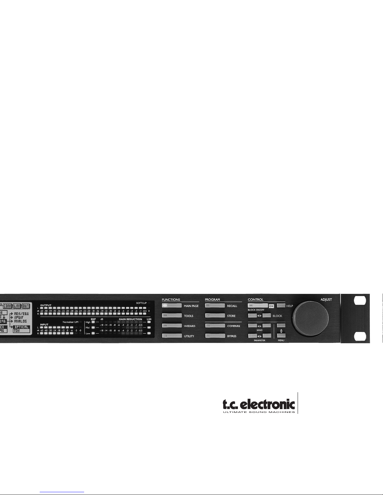
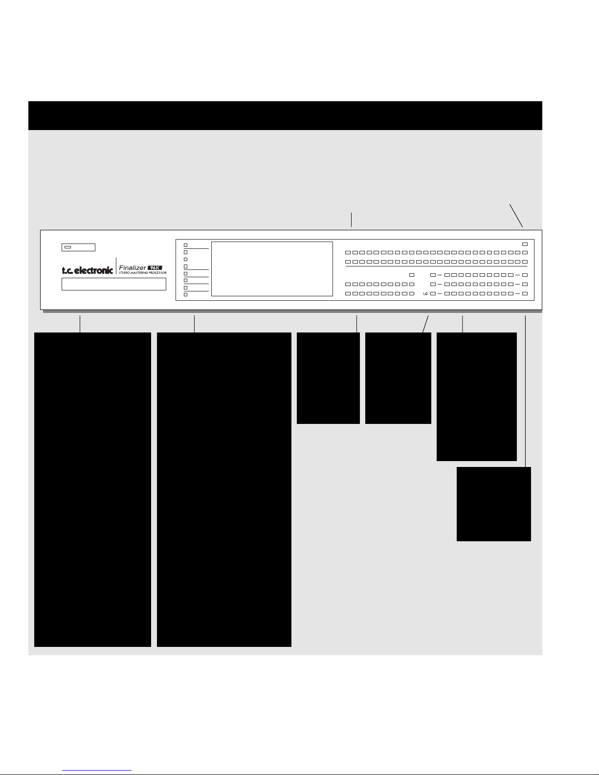
FRONT PANEL
INDICATORS
Overload
Indicates internal overload.
In the Tool/Flow menu you
can see exactly where the
overload occurs.
Sample Rate Indicator
48000Hz
44100Hz
32000Hz
If no valid Clock Rate is present all three LEDs will blink.
MIDI In
MIDI receive indicator.
Card
Indicates when data is transferred to or from the card.
Working
Indicates when brief
calculations take place.
Edited
Preset has been edited.
POWER &
MEMORY CARD
Electronic power switch
»Easy touch«
Turn on the machine with
a single light touch. To
turn off the machine you
must press and hold
down the POWER key
approx. 3 seconds until
the display reads
Finalizer.
PC-CARD memory card
Copy presets to/from a
standard memory card.
Card types
S-RAM Type 1 PCMCIA
cards, with a minimum of
64KB and a maximum of
2MB memory.
POWER
MIDI IN
48000Hz
OVERLOAD
44100Hz
32000Hz
CARD
WORKING
EDITED
-1 -0.5
-2
-2
0
-1
-1
OUTPUT
L
L
R
R
INPUT
GAIN REDUCTION LIM
EXP
Normalizer LIM
SOFTCLIP
HI
MI
-10-12-14-16-18-20-22-24-0-26-3-28-6-30-9-32
-12-18
-36-44-48-60 -40
-24-30-40-60
-8
-24 -20
-24 -20
-16
-16
-6 -5
-12
-12
-4
-8-8-10
-10
-3
-6
-6
-2
-4
-4
dB
dB
dB
Output PPM
High resolution meters
SOFTCLIP LED
Indicates when
the Soft Clipper
is active
INPUT PPM
Range:
-60dBFS to
0dBFS.
COMPRESSOR
GAIN
REDUCTION
METERS
Indicates the
amount of
Compressor gain
reduction.
EXPANDER
INDICATORS
Indicates
when the
Expander is
active.
LIMIT LEDs
Indicates when
the Limiter is
active.
Page 7
7
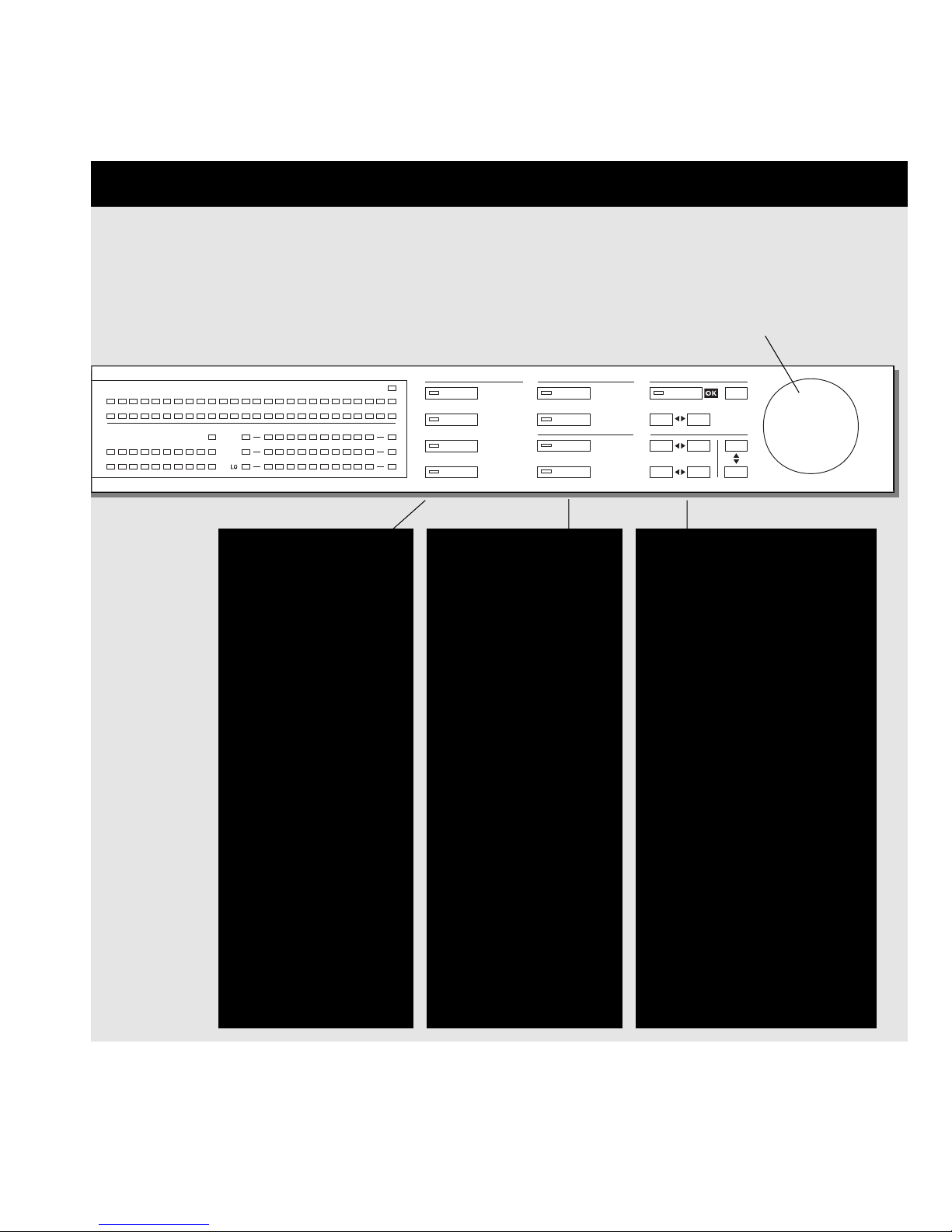
FUNCTIONS SECTION
MAIN PAGE
This key gives you access
to edit the entire signal flow,
from Input to Output.
TOOLS
Press this key and gain
access to the following tools:
Flow meter, Peak meter,
Phase correlation, DIO
(monitors Digital In/Out
signal) and Calibration.
WIZARD
Use The Wizard to quickly
find the optimal settings for
your program material.
UTILITY
MIDI, Security, Memory
management and much
more is located here.
PROGRAM SECTION
RECALL
Recall presets.
STORE
Store and name presets.
COMPARE
Compare the sound you
have right now with either a
level compensated bypass
or the original preset.
BYPASS
Bypass the signal processing.
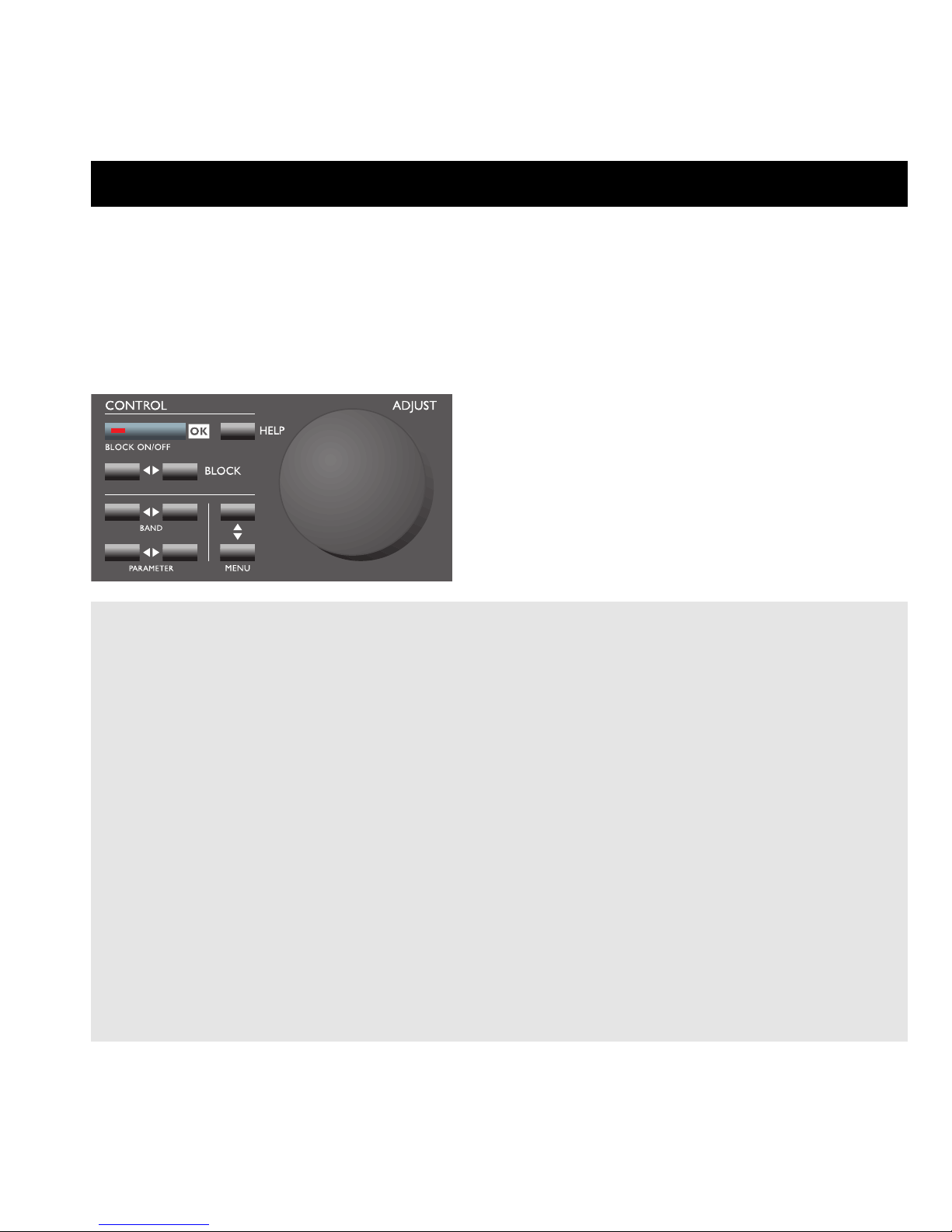
CONTROL SECTION
OK
Confirm operations
and switch individual blocks on/off.
HELP
Get help on selected display function.
BLOCK < >
Select which block to edit in the
Main page.
MENU up/down
Vertically oriented menu selector.
PARAMETER < >
Moves cursor horizontally for
selection of parameter to be modified.
BAND < >
Select between the three bands
on the Com/Lim/Exp pages.
Select which band to modify in the
EQ block.
WIZARD
BLOCK ON/OFF
MENU
PARAMETER
BAND
QUICK STORE
ADJUST
BLOCK
HELP
RECALL
MAIN PAGE
STORE
TOOLS
COMPARE
WIZARD
BYPASS
UTILITY
FUNCTIONS
PROGRAM CONTROL
-1 -0.5
-2
-2
0
-1
-1
OUTPUT
L
L
R
R
INPUT
GAIN REDUCTION LIM
EXP
Normalizer LIM
SOFTCLIP
HI
MI
-10-12-14-16-18-20-22-24-0-26-3-28-6-30-9-32
-12-18
-36-44-48-60 -40
-24-30-40-60
-8
-24 -20
-24 -20
-16
-16
-6 -5
-12
-12
-4
-8-8-10
-10
-3
-6
-6
-2
-4
-4
dB
dB
dB
ADJUST wheel
Sets parameter values and
preset numbers.
Page 8
8
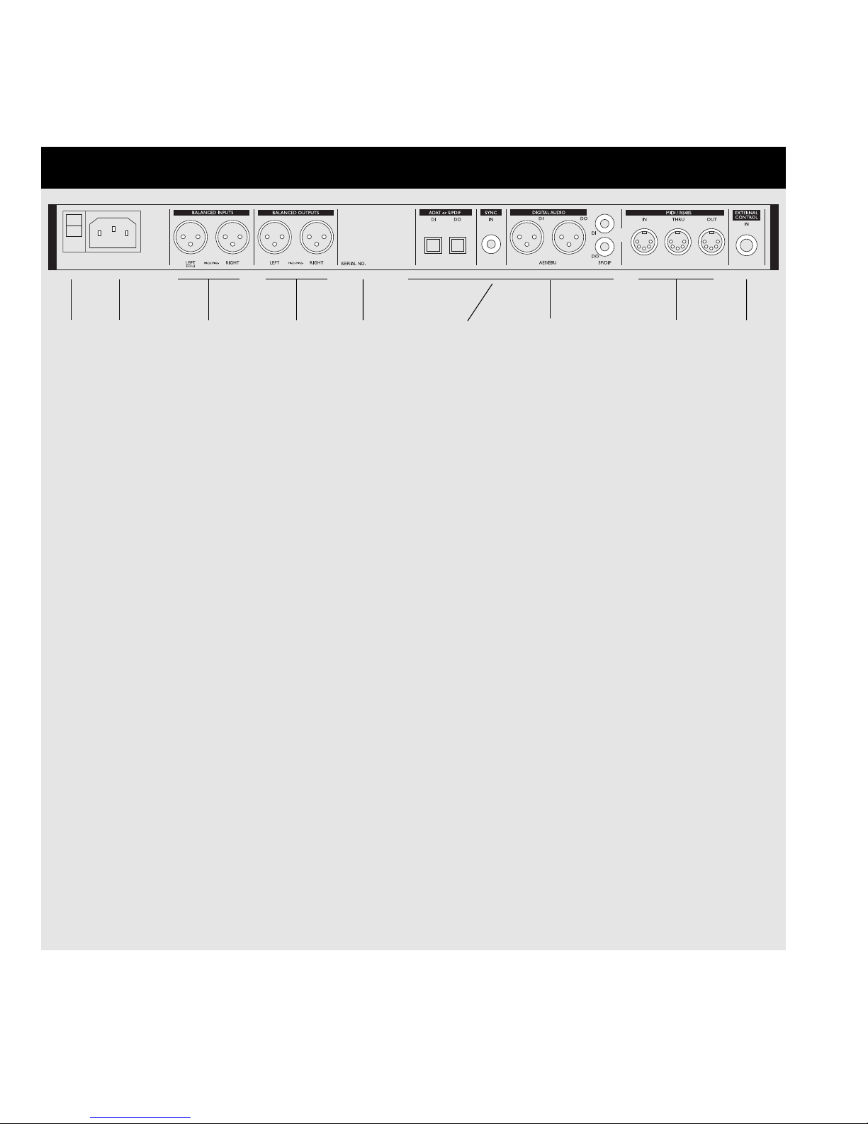
REAR PANEL
The Sync In
This word clock Input gives you the following functions:
- External reference for A/D or D/A
- External reference for Sample Rate Conversion
- External reference for Digital Inputs
The Input impedance is 75 ohm. A BNC to RCA Phono converter plug is included with your Finalizer for connection with equipment carrying BNC word clock connectors.
If you are connecting the Finalizer to unbalanced equipment, you must tie pins 1 and 3 together in the cable
ends away from the Finalizer.
Please refer to page 52 for soldering instructions of the different cable types.
Main
Power
Switch
Power
Input
Balanced
XLR
Inputs
Balanced
XLR
Outputs
Serial
no.
Digital In/Out
AES/EBU
S/PDIF, ADAT
Tos-link
Wordclock
Sync
Input
MIDI
In, Thru, Out
Pedal/
Fader
Input
Page 9
9
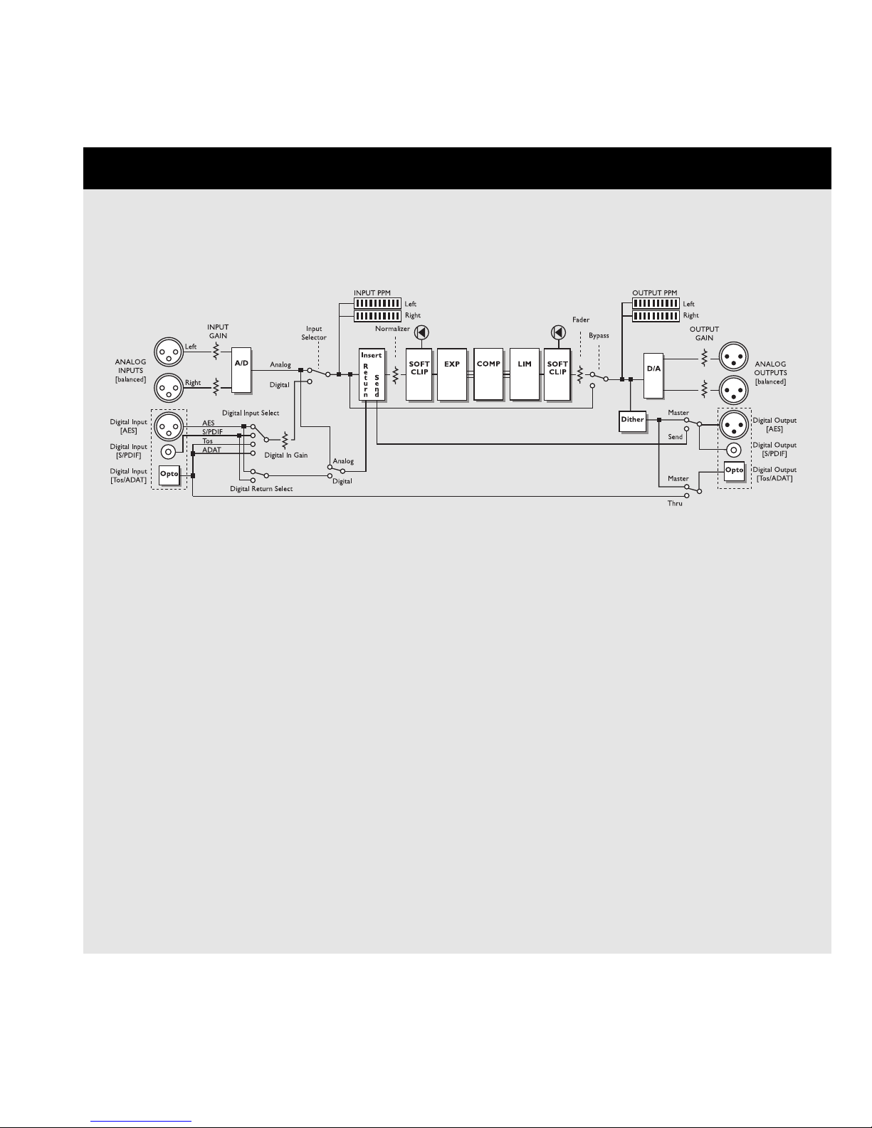
SIGNAL FLOW
Notes regarding the signal flow:
Since the Finalizer is using 24 A/D-D/A converters, Dithering is available on Digital Outputs only.
Page 10
10
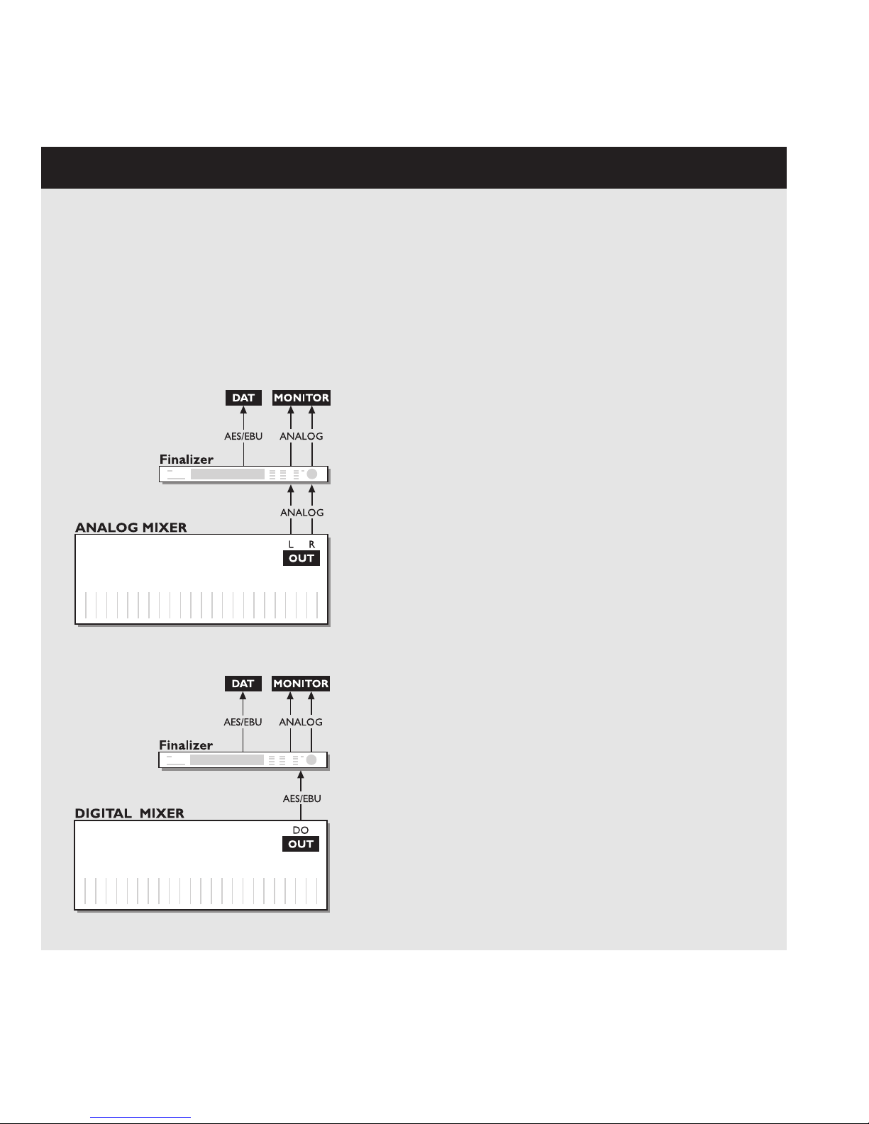
FINALIZER SETUP
Setup with an Analog mixing console and a Digital
recording device.
1. Connect the Analog Output of your mixer to the Analog Input of
the Finalizer.
2. Connect the Digital Output of the Finalizer to the Input of your
Digital recording device.
3. Connect the Analog Output of the Finalizer to your
monitor system.
Example 1
Example 2
Setup with a Digital mixing console and a Digital
recording device
1. Connect the Digital Output of your mixer to the Digital Input of
the Finalizer.
2. Connect the Digital Output of the Finalizer to the Input of
your Digital recording device.
3. Connect the Analog Output of the Finalizer to
your monitor system.
Finalizer Setup
The Finalizer is carefully designed to optimize the overall level and enhance the energy and clarity in your mix.
The use of the three band Compressor, Limiter and Expander makes the dynamics section of the Finalizer very flexible, while
maintaining the fidelity of the original material. The dynamics section, in a combination with a Normalizer and a five band
Equalizer, gives you a very powerful tool, to finish the last details of your mix.
Because the Finalizer can be used with different applications, we propose a couple of different setups.
Page 11
11
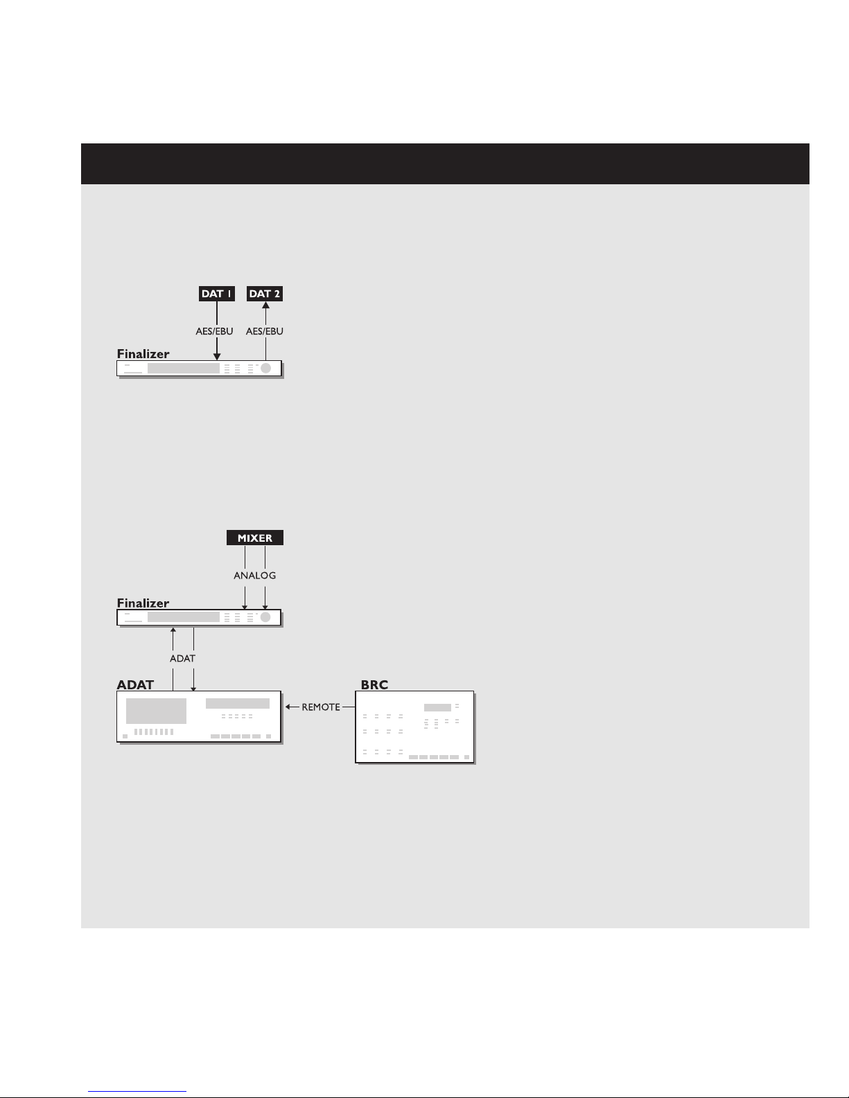
Example 3
Mastering from DAT to DAT
1. Connect the Digital Output of DAT #1 to the Digital Input
of the Finalizer.
2. Connect the Digital Output of the Finalizer to the Digital
Input of DAT #2.
Using the Finalizer with ADAT and BRC
1. Connect the Finalizers optical out to the ADATs optical in.
2. Connect the ADATs optical out to the Finalizers optical in.
3. Enter the In section of the Finalizer (Main page) and set the
"Clock" to "ADAT".
This will force the Finalizer to follow the clock of the ADAT.
Note: This is only possible when using the Analog Inputs of the Finalizer.
Example 4
FINALIZER SETUP
Page 12
12
Preset banks
Factory
presets
Your own
presets
The Finalizer contains two different preset banks. A RAM bank
and a ROM bank.
Finalizer PLUS :
The ROM bank holds 28 presets
The RAM bank holds up to 128 presets.
Finalizer 96 :
The ROM bank holds 30 presets
The RAM bank holds up to 128 presets.
The RAM preset bank is located after the ROM bank. This means
that you scroll through the ROM presets to enter the RAM bank.
For fast RAM/ROM access use the BLOCK keys
to switch between the two banks.
Note: When previewing in the RAM bank you will not see the
empty RAM spaces.
Factory/User presets
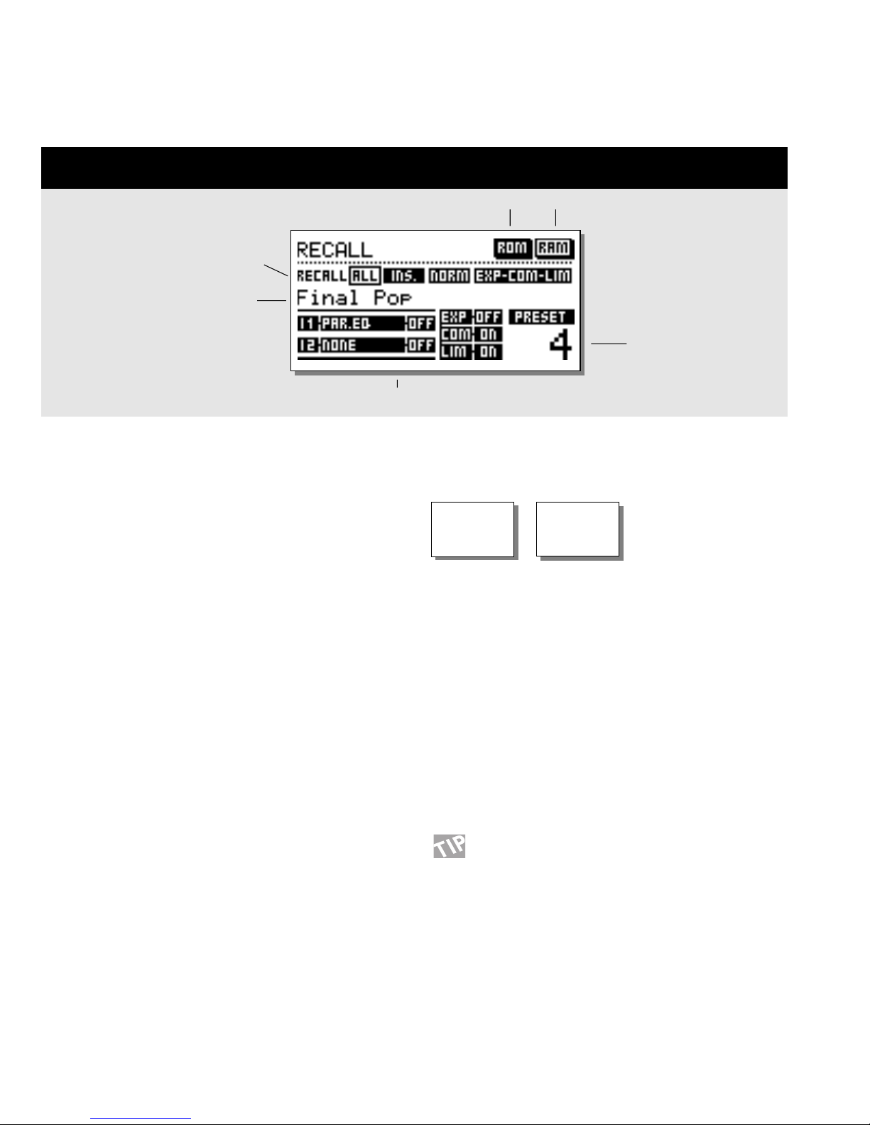
RECALL
Select which blocks to load from
new preset.
Preset name
Preset number
ROM bank
RAM bank
Recalling a preset
Press the RECALL key in the Program section and
scroll through the presets using the ADJUST wheel.
Press OK to recall when you find the desired preset.
You are able to search for another preset before recalling it. This
is called previewing. Until you press OK you are previewing. At
this point your OK key is blinking, indicating that the preset displayed is not yet recalled (active).
The Recall Display
In the Recall display, you will see an information section at the
bottom of the screen. In this section you are able to see which
blocks are activated in the current preset. In the upper right
corner, you see an indication of which bank you are previewing.
Partial Recall
It is also possible to recall separate sections of a preset. This is
extremely useful when you want to combine, lets say your
favorite settings of the Normalizer from one preset, with your
favorite EQ settings from another preset.
Exercise 1:
How to make a Partial Recall
Scenario: You love preset no. 3 but would like to use the
Normalizer from ROM preset no. 6.
- Select ROM preset no. 3.
- All is now highlighted (transparent) in the Recall display.
- Use the PARAMETER keys to select the Normalizer block.
- Use the ADJUST wheel to select ROM preset no. 6
and press OK.
The Normalizer from preset no. 6 is now recalled into
preset no. 3.
Short info about the preset
128 RAM
PRESETS
28/30 ROM
PRESETS
Page 13
13
STORE
Storing a User preset and handling preset names
Storing a preset with the same name:
- Press the STORE key
- Select a location for your new preset using the ADJUST wheel
(You can store your preset in the RAM bank only, and the Finalizer therefore automatically selects this bank)
- Press OK and the preset is stored with the same name at the selected location
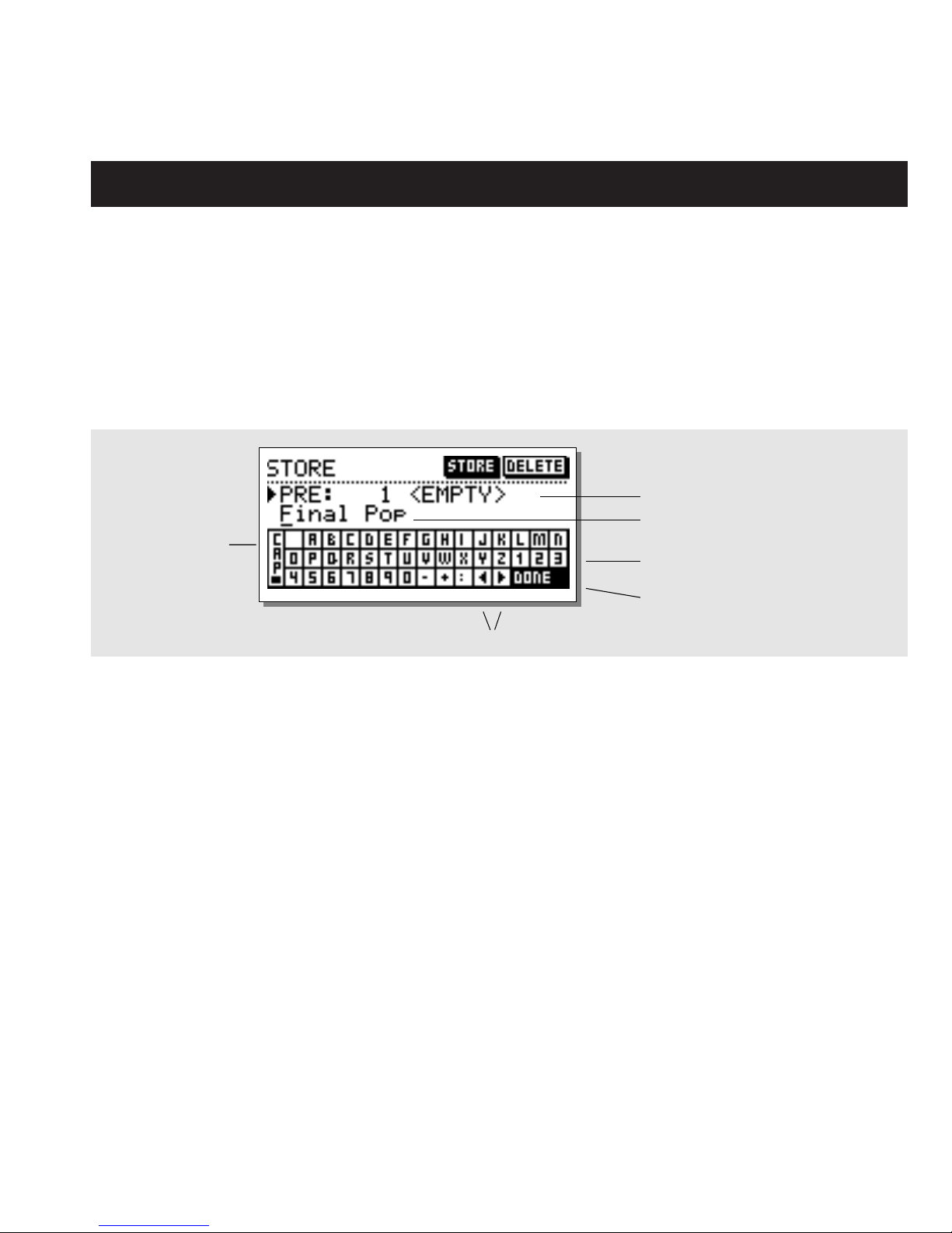
Storing a preset with a new name:
- Move the cursor, using the MENU keys, to select the name line
- Type the new preset name. (Select letters with the ADJUST wheel and confirm each letter with OK.
Note that you can always move the cursor using the PARAMETER keys)
- To store the preset with the new name select DONE in the Letterbox and press OK
Store location
What is stored where?
Global parameters
Global parameters (or system parameters) are not affected by
preset recalls. The parameters include:
- Input and Output blocks on the Main page (except Lo-cut):
Formats, I/O levels, Insert Enable and Dither.
- Parameters in the Utility page.
- Parameters in the Tools Digital out page.
To reset the Global parameters, follow the guidelines on page 42
of this manual.
Preset parameters
Preset parameters may change with every preset and when the
Wizard is invoked. They are modified in most Blocks of the
Main page. Exceptions are the In and Out Blocks. (However, Locut in the In block is also part of a preset).
Preset name
Letterbox
Cursor arrows
CAPS LOCK
Indicator
Place cursor here and press OK
to finalize the store operation
Note: Asking for an External Insert is part of a preset. Enabling
a specific External Insert is part of the Global parameters.
When an Analog Insert is specified, the I/O interface levels are
stored with the preset.
Using a Memory card:
Insert the card. The Finalizer will now autodetect your card and
the Store and Recall facilities will be attached to the memory
card. The Finalizer will now use the memory card as its RAM
bank. When you remove your memory card, the Finalizer will
switch back to the internal RAM bank.
If the format of the memory card is not correct, the Finalizer will
detect this immediately. The card will automatically be formatted
the first time you save or dump information to the card.
Note: This will destroy all exsisting information on the card.
Card types
S-RAM Type 1 PCMCIA cards, with a minimum of 64 KB and a
maximum of 2 MB memory.
Page 14
14
MAIN PAGE Input
Select the In section on the Main page using the
BLOCK keys.
The global level controls should be set to optimize the
performance of the 24 bit A/D converter in the
Finalizer.
The In block is divided into two pages accessible by
using the MENU keys. The Input choice in page 1
enables or disables other parameters such as External
Insert and Sample Rate Conversion and the Input
choice should therefore be carried out as step no. 1.
Please note that the DSP MODE 48/96 is available
only in the Finalizer 96.
Basic operation
Press the PARAMETER keys to move the cursor, and turn the
ADJUST wheel to change values.
Page 1
This page is identical to page 1 in the Out block
Considerations setting up the Input page:
Maximum A/D performance
When converting from Analog to Digital, maximum A/D
performance is crucial to maintain the maximum quality. In order
to achieve this, the A/D converter should be given the best
operational conditions. Setting the clock of the converter is one of
the points where you have to carefully consider your choice.
The ideal situation for any converter is to use the internal clock of
the converter itself. This will ensure a minimum of artifacts like
jitter.
Input Sample Rate and Sample Rate Conversion (SRC)
When a Digital Input is used, the transmitting device and the
Finalizer need to run at the same Clock Rate, or Sample Rate
Conversion (SRC) must to be used.
If the SRC is off, you have to set either the Finalizer in External
Clock mode, or the transmitting device must get a Clock Rate
from the Finalizer running in internal clock mode.
To test the Digital connection, try listening for a minute or so to a
sine tone at e.g. -18dBFS generated by the transmitting device. If
you hear no distortion or glitches, youve probably got it right.
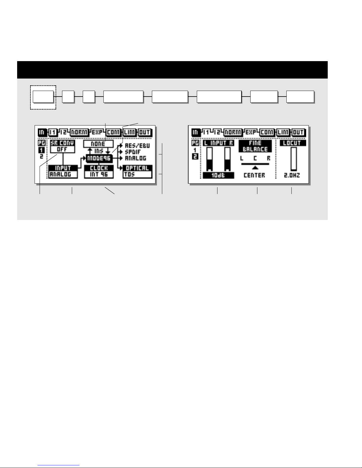
INPUT
Input type
select
Clock
select
Digital Output
formats
I 2I 1 NORMALIZER EXPANDER COMPRESSOR LIMITER OUTPUT
Left/Right
Input level
L/R Fine
adjust
LoCut
Frequency
Sample Rate
Conversion
on/off
In page no 1 In page no 2
Insert
Mode selector
Page 15

15
MAIN PAGE Input
Sample Rate Conversion may be applied to the AES/EBU,
S/PDIF or Tos-link Input. The Input Sample rate is asynchronous,
with the Output of the Sample Rate Converter locked to the
system Clock source.
Internal references at 44.1and 48 or an external Word Clock
signal may be used to drive the Sample Rate Converter.
Sample Rate LEDs
When a Digital Input is used, and the signal is recognized, one of
the three yellow Rate LEDs light up. If no signal is present, and
youve selected a Digital Input or Insert, all three LEDs will blink.
Note: Blinking LEDs indicate an error condition. The Outputs of
the Finalizer are muted.
Digital Input Formats and levels
Several Digital Input formats are supported: AES/EBU, S/PDIF,
Tos-link and ADAT. If you select ADAT format, you are allowed
to pick two independent tracks for processing in the Finalizer.
Format conversions between any of the mentioned formats are
available.
Level calibrations are easily maintained in the Digital domain.
However, with a Digital Input selected, level and balance
adjustments may be performed digitally in Input page 2.
When a Digital Input is selected, the Clock selection defaults to
EXT DI (External Digital In). This selection may be overruled as
explained in the Sample Rate.
Mode 48/96
Mode 48 gives you a maximum frequency response of 24kHz.
Mode 96* (Double Sample Rate) gives you a maximum
frequency response of 48kHz.
Unlimited Up and Down Sampling
Sample Rate Conversion between all Sample Rates is possible.
Input Sample Rates of 44.1, 48, 88.2 or 96kHz is accepted and
can be up/down-sampled to 44.1, 48, 88.2 or 96kHz.
This up and down sampling feature is available from software
version 3.50 and up and requires a minor hardware upgrade.
Please contact your local dealer for further information regarding
upgrade procedure and upgrade fee.
The new hardware is installed from factory in Finalizer 96Ks
with serial no. 1214250 and above. To see if the new hardware is
installed: Install the 3.5 software and reboot the unit. If the
Up/Down sampling logo appears during power-up, both software
and hardware is installed
Note: Software 3.5 will operate on Finalizer PLUS and old Finalizer
96K, but the up/downsampling feature is available only in
conjunction with the hardware update.
Example 1:
You have a Digital signal at a Sample Rate of 96kHz present on
the Input and you wish to have a signal at a Sample Rate of
44.1kHz on the Output.
- Select Digital Input type: S/PDIF, AES/EBU or Tos.
- Set the Sample Rate Conversion SRC to On.
- Select Mode48.
- Select Output Clock frequence 44.1kHz.
You now have a Clock Rate on the Output of 44.1kHz
Example 2:
You have a Digital signal at a Sample Rate of 44.1kHz present
on the Input and you wish to have a signal at a Sample Rate of
96kHz on the Output.
- Select Digital Input type: S/PDIF, AES/EBU or Tos.
- Set the Sample Rate Conversion SRC to On.
- Select Mode96.
- Select Output Clock frequence 96kHz.
You now have a Clock Rate on the Output of 96kHz
Example 3:
You have an Analog signal on the Input and you wish to have a
signal at a Sample Rate of 96kHz on the Output.
- Select Input type: Analog.
- Sample Rate Conversion is automatically set to Off.
- Select Mode 96.
- Select Output Clock frequence 96kHz.
You now have a Clock Rate on the Output of 96kHz.
Clock - Sample Rate
Select which clock you want the Finalizer to sync to.
Mode 48: Internal 44,1, Internal 48, External sync. or External
Sync, AES/EBU, S/PDIF or ADAT.
Mode 96*: Internal 88,2, Internal 96, External sync. or External
Sync, AES/EBU, S/PDIF or ADAT.
Optical - Digital Output Formats
The available Output formats are determined by the Input and
Insert selections. Optical Outputs may be chosen between ADAT,
Tos-link and Thru.
- When ADAT is selected, you may assign the Finalizer
signals to any two ADAT channels.
- When Thru is selected, the Optical Output is a copy of the
Optical Input, regardless of format.
* 96kHz is only available in Finalizer 96. MODE 96 must be
selected.
Page 16

16
MAIN PAGE Input
Page 2
Use the MENU keys to switch between page 1 and 2
Analog Input Level
When Analog Input is selected, Analog gain up to +26dB, or
attenuation to -6dB before the A/D converters may be applied.
For professional signal interfacing, the Level control should
normally be positioned between -6 and +6dB corresponding
with a 0dBFS signal at +22 to +10dBu. If you need more than
6dB gain you should consider raising the Output of the
transmitting device.
For consumer signal interfacing the Level control should
normally be positioned between +18dB and +6dB.
When Analog Input is selected the Clock selection defaults to
INT 48 (Internal 48kHz). This selection may be overruled as
explained in the Sample Rate section.
Fine Balance
Set the balance of the Left/Right channels.
Ranges: 0 to -3dB Left/Right.
LoCut
The LoCut filter is global, and is used to filter out any sub-bass
frequency or DC contents in the current signal.
Note: The LoCut filter might introduce occasional overshoots
when Hot signals are Input.
Finalizer & ADAT
When using the Finalizer in a setup with ADATs there are a
couple of recommendations to keep in mind.
There are two different situations: An ADAT setup with BRC
(Big Remote Control), and an ADAT setup without BRC.
If the BRC is not connected, the ADAT should be slaved to
incoming Finalizer Clock. Use the following:
1. Connect the Finalizers optical out to the ADAT optical in.
2. Select "Digital in" on the ADAT.
The ADAT will now use the Finalizer clock.
Note: Slaving the Finalizer to the ADAT clock will reduce the
Finalizers A/D converter performance.
When using the Finalizer with ADATs and a BRC it is
recommendable to use this setup:
1. Connect the Finalizers optical out to the ADAT optical in.
2. Connect the ADATs optical out to Finalizer optical in.
3. Enter the In section of the Finalizer (Mainpage) and set the
"Clock" to "ADAT".
This will force the Finalizer to follow the clock of the ADAT.
Note: This is only possible when using the Analog Inputs of the
Finalizer.
The ADAT is forced to follow the clock of the BRC. In order to
synchronize the Finalizer to the ADAT, the clock of the ADAT
is used as master clock in the Finalizer.
Insert - External Insert
Instead of internal processing, one of the two Insert points may
be set up for external processing. The Ext. Insert may be
Analog, AES/EBU or S/PDIF depending on your Input choice.
When a Digital Input is selected only an Analog Insert can be
used.
Note: Asking for an External Insert is part of a preset.
Enabling a specific External Insert is part of the Global
parameters - set in In page 1.
When an Analog Insert is specified, the I/O interface levels are
stored with the preset.
If a preset containing an Ext. Insert is recalled, but no Ext.
Insert is available in your current setup, the External Insert is
disabled but still shown in the Insert page, until you change the
Insert configuration in the In or Out page.
Page 17

17
This page is intentionally blank
Page 18

18
MAIN PAGE Inserts
Insert type selector
Select between:
- None
- Digital Radiance
- Stereo Adjust
- Dyn EQ
- Parametric EQ
- External Insert
- MS Encoding/Decoding
- Spectral Stereo Image
(Finalizer 96 only)
Insert selected
This parameter determines the drive of the
Digital Radiance
Generator
Shows the performance of the Digital
Radiance Generator
Move cursor up to increase the stereo width
Move cursor down to make the signal more mono
Center position is normal.
Move the cursor Left/Right to adjust center (balance)
STEREO ADJUST
DIGITAL RADIANCE GENERATOR
THRESHOLD
RATIO
ATTACK
RELEASE
FREQUENCY sets the working
frequency of the Dynamic EQ
CURVE sets the frequency
characteristics of the dynamic
damping filter
DYN-EQ
INPUT I 2I 1 NORMALIZER EXPANDER COMPRESSOR LIMITER OUTPUT
Page 19

19
MAIN PAGE Inserts
Inserts
Select Insert 1 or 2 using the BLOCK keys
The Finalizer has various Insert possibilities. Choose between:
None, DRG (Digital Radiance Generator), Stereo Adjust,
Dynamic EQ, Parametric EQ, Ext Insert or MS Encoding/
Decoding or Spectral Stereo Image (only available in
Finalizer 96).
Note: You can use only one Insert type at a time.
E.g. not two parametric EQs at the same time.
Basic operation
- Select Insert 1 or 2 using the BLOCK keys.
- Use the MENU keys to highlight the Insert type.
- Use the ADJUST wheel to select Insert type.
- Press the PARAMETER keys to select parameter.
- Turn the ADJUST wheel to change values.
Digital Radiance Generator
The DRG (Digital Radiance Generator) adds second harmonic
distortion to the signal. This kind of distortion is very
Analog-like, and will add a certain warmth to your material.
Drive
The DRG drive is adjustable from 0 to 10.
Curve
The Curve parameter changes the face of the second harmonics
added by the DRG.
If your material is asymmetric (percussion/speech, etc.), the
plus/minus parameter will change the sound of the DRG.
Please try this and listen.
Stereo Adjust
With Stereo Adjust, you can change the stereo information
content of the signal. Turn the MS (M-mono, S-stereo), parameter clockwise to increase stereo width, and counter-clockwise to
make the signal more mono-like.
You can change the Left/Right balance with the LR parameter.
Dynamic Equalizer
The Dynamic Equalizer is somewhat like an extended
De-esser with more parameters and enlarged
frequency range, enabling better control. You can also
look at the Dynamic Equalizer (and a De-esser) as a
Compressor that works in a defined and limited part of
the frequency range.
Threshold
When the Input level exceeds the Threshold, the Dynamic
Equalizer will be activated.
Ratio
The Ratio of the gain reduction. When the Ratio is set to 4:1 it
means that for every 4dB the defined frequency range rises above
Threshold, the Output level of the specified frequency is
increased by only 1dB.
Attack
The Attack time is the response time that the Dynamic EQ uses
to reach the gain reduction specified by the Ratio parameter.
Example: If the Input signal increases to 4dB above Threshold
with the Ratio set to 4:1 and the Attack set to 20ms, the Dynamic
EQ will use 20ms to reach the gain reduction of 3dB.
Release
Release sets the fall-back time of the Dynamic EQ, after the
signal drops below the Threshold.
Frequency
The frequency sets the working frequency of the Dynamic EQ.
Curve
With the curve parameter, you select whether the Dynamic EQ
should work with a bell-shaped or shelving filter.
Page 20

20
Black box indicates selected block Selected band
Frequency Gain
Bandwidth/Slope
EQ
Basic operation
Press the PARAMETER keys to select frequency/gain/
bandwidth/slope.
Turn ADJUST wheel to change values.
Press BAND keys to jump between the five bands.
EQ Ranges
Type Frequency Bandwidth/Slope
Low Shelve 19.95Hz to 5.01kHz 3, 6, 9, 12 dB/Oct
Bell-shaped filter 1 19.95Hz to 20kHz 0.1 Oct to 4.0 Oct
Bell-shaped filter 2 19.95Hz to 20kHz 0.1 Oct to 4.0 Oct
Bell-shaped filter 3 19.95Hz to 20kHz 0.1 Oct to 4.0 Oct
High Shelve 501.2Hz to 20kHz 3, 6, 9, 12dB/Oct
Gain Range for all filters and Output: +/- 12dB
EQ Bypass
Press the OK key to bypass the Insert section.
Reset all filters by pressing both BAND keys
simultaneously.
MAIN PAGE Inserts
INPUT I 2I 1 NORMALIZER EXPANDER COMPRESSOR LIMITER OUTPUT
Insert Type
Level bar
External Insert
Instead of internal processing, one of the two Insert points may be
set up for external processing. The External Insert may be Analog,
AES/EBU or S/PDIF depending on your Input choice.
Note: Asking for an External Insert is part of a preset. Enabling a
specific External Insert is part of the Global parameters. When an
Analog Insert is specified, the I/O interface levels are stored with
the preset.
If a preset containing an External Insert is called, and no such
thing is available in your current setup, the External Insert is
disabled but shown in the Insert page, until you change the Insert
configuration in the In or Out-page.
Page 21

21
MAIN PAGE Inserts
MS Encoding/Decoding
MS miking technique or Mid/Side uses a forward-facing
directional mic and a side-facing bi-directional mic.
MS recording offers very good stereo imaging with the added
benefit of excellent mono compatibility. Through the electronic
process of MS Encoding and Decoding, the two mic signals can
be combined to create a stereo signal either before recording or
on playback. The Finalizer offers MS Encoding and Decoding.
- MS Encoding will change a regular Left/Right signal into a
Mid/Side signal.
- The Fine Balance control will allow you to adjust the
relationship between the Mid/Side signals.
- MS Decoding will change a Mid/Side signal into a Left/Right
signal
- The Balance control will allow you to change the relationship
between the Mid/Side signals.
Try lowering the Mid signal by a few dB. This is
what is perceived as an enhancement of the
overall Stereo image.
Balance adjust
INPUT I 2I 1 NORMALIZER EXPANDER COMPRESSOR LIMITER OUTPUT
Spectral Stereo Image
This feature is only available in Finalizer 96
This function allows you to control the stereo width of your
signal in three independent bands by adding or subtracting stereo
information. Selecting values above 0 (Normal) will enhance the
stereo information in the selected band, while values below 0 will
reduce stereo information.
Use the CURSOR keys to select the desired parameter and dial
the ADJUST wheel to change values.
Note that enhancing the Stereo Image might reduce the overall
level. This can be compensated by increasing the level by 1-3dB
in the Normalizer.
Try enhancing the Stereo Image in the Mid and
High band, while leaving the Low band
untouched. This will widen the vocal and cymbal
area while maintaining the punch from the
bassdrum.
Page 22

22
MAIN PAGE Normalizer
Effects blocks
Black box indicates selected block
No. of consecutive
samples clipped.
Normalizing gain
Clipping method
Normalizer
The process of optimizing the level of your material begins in
the Normalizer. Here you have a graphical presentation of the
incoming signal, shown as 1 second pictures.
By increasing the gain, you decrease the headroom, shown as
two dotted lines.
You should set the gain so the signal peaks are just hitting the
dotted headroom lines.
The Normalizer is capable of gaining +18dB.
The Clipper
The Softclipper smoothly eliminates any overshoot that might
occur. Please note that if you drive the Clipper too hard, you
might introduce noticeable distortion on signals with a low
harmonic content and/or on very pure signals. The distortion
introduced is somewhat similar to the tape saturation that can
occur when overdriving an Analog tape recorder.
When processing delicate material, such as classical
instruments, you should disable the soft clipper, to utilize the
full dynamic spectrum of these instruments. Use the Hard Clip
function instead (normal Digital clipping).
INPUT I 2I 1 NORMALIZER EXPANDER COMPRESSOR LIMITER OUTPUT
The Clip counter indicates the maximum number of consecutive
samples clipped within the last second.
The Normalizer has a built-in Limiter, which can be either soft or
hard. The Normalizer LIM LED above the Input meters will indicate if the Normalizer is hardclipping.
Page 23

23
This page is intentionally blank
Page 24

MAIN PAGE Expander
Y-axis is Output
level.
USER PAGE
EXPERT PAGE
Edit guide
Arrow direction indicates whether
the parameter value has been
increased or decreased since last
recall. A dot indicates no changes.
Please see the Edit guide
description at page 27.
PAGES
- User page
- Expert page
- Cross-over frequency page
X-axis is Input
level.
Expander
Threshold
low/mid/high
Attack time
low/mid/high
Release
time
low/mid/high
Side chain/delay
This parameter inserts the indicated delay in
the main signal path.
The side chain will therefore be able to look
ahead on the Input signal, enabling the
Expander to respond faster to sudden signal
changes.
This parameter is common for
Expander/Compressor/Limiter.
Ratio
low/mid/high
Use band select cursors to access
individual bands.
CROSS-OVER FREQUENCY PAGE
24
INPUT I 2I 1 NORMALIZER EXPANDER COMPRESSOR LIMITER OUTPUT
Range
Maximum gain
reduction in the
Expander.
Page 25

25
Expert Menu
Press MENU keys to enter expert mode (XPRT)
Attack
Use the ADJUST wheel to change the Attack time of the three
bands. The Attack is the time the Expander uses to bring the
reduced signal to 1:1, when the signal exceeds the Threshold.
Release
Use the ADJUST wheel to change the Release time of the three
bands. The Release time is the time the Expander uses to reach
the the gain reduction specified by the Ratio parameter.
Example: If the Input signal drops 4dB below Threshold, with
the Ratio set to 1:4 and the Release time set to 20 ms, the
Finalizer will use 20 ms to reach a total gain reduction of 16dB.
Side Chain / Delay
This parameter adjusts the look-ahead delay. This means that
your audio signal is delayed, e.g. 10 ms.
By slightly delaying the audio signal, you give the processor a
chance to look ahead at the present signal, and the reaction will
therefore be more accurate than a standard Compressor/Limiter/
Expander.
The actual look-ahead delay time is scaled with the Attack time
individually on all three bands.
Note: This delay time parameter is common for the Compressor,
Limiter and Expander.
Cross-over Menu
Press MENU keys to enter the Cross-over frequency
page (Xovr)
L-Xovr/H-Xovr
With the L-Xovr and H-Xovr you set the Cross-over points of the
three bands in the dynamics section.
Note: The Cross-over points are common for the Compressor,
Limiter and Expander.
Range
The Expander range determines the maximum amount of gain
reduction in the Expander, e.g. when set to 6dB, the Expander
will only reduce the output by 6dB no matter how much the
signal drops below threshold. This enables you to use the
Expander to simply reduce the signal below a certain threshold
instead of a complete shut-off.
Expander Bypass
Press the blue OK key to bypass the Expander section.
Expander
Expander/Gates are often used to remove unwanted background
noise. Both the Gate and the Expander perform what is called
Downward Expansion. In general this means that below a
certain Threshold the Input signal gain is reduced on the Output
according to a specific Ratio. If for instance the Expander has a
Ratio of 1:2, the Output is decreased with 2dB for every single
dB the Input is decreased below Threshold.
Select EXP by pressing the BLOCK keys
Basic Operation
- Press the PARAMETER keys to select parameter.
- Turn the ADJUST wheel to change values.
- Press the BAND keys to select between the three bands.
- Press the MENU keys to select User/Xpert/Xover.
User Menu
Threshold
Use the ADJUST wheel to change the Threshold of the three
bands. When the input signal drops below the Threshold the
Expander is activated. As you can see in the diagram above: the
higher a Threshold point, the more expansion you will get.
Ratio
The Ratio of the gain reduction. Use these parameters to adjust
the Ratios of the three Expander bands. If the Ratio is set to 4:1
you will get a 4dB decrease of the Output signal for every 1dB
the Input signal is decreased below Threshold.
Expander Monitor
The Expander Monitor gives you a graphical picture of the Ratio
and Threshold settings.
The Edit Guide
Please see description on page 27.
MAIN PAGE Expander
Page 26

26
MAIN PAGE Compressor
USER PAGE
EXPERT PAGE
Page select:
Threshold
low/mid/high
Ratio
low/mid/high
Band levels
low/mid/high
Output level
Attack
Times
low/mid/high
Release
Times
low/mid/high
Crest
This parameter determines
whether the Compressor
should react to peaks,
RMS (average), or
something in between.
Sidechain / Delay
(same as Expander)
CROSS-OVER FREQUENCY PAGE
INPUT I 2I 1 NORMALIZER EXPANDER COMPRESSOR LIMITER OUTPUT
Edit guide
Arrow direction indicates whether
the parameter value has been
increased or decreased since last
recall. A dot indicates no changes.
Please see the Edit guide
description at page 27.
Page 27

27
The Compressor
A Compressor is meant to reduce the dynamic content of the
Input signal, and thereby keep a more constant level. When the
Input signal exceeds the Threshold, the Compressor starts to
reduce the signal according to the Ratio. The Ratio describes how
much the signal is reduced, e.g. a Ratio at 2:1 means that for
every 2dB the Input signal exceeds the Threshold, only 1dB is
Output.
Select COM by pressing the BLOCK keys
Basic operation
- Press the PARAMETER keys to select parameter.
- Turn the ADJUST wheel to change values.
- Press the BAND keys to select between the three bands.
- Press the MENU keys to select User/Xpert/Xover.
About the Compressor
The Compressor section of the Finalizer is divided into three
bands. This means that you are able to compress the low/mid/high
frequencies separately.
To optimize the Output gain and energy in your material, the
Finalizer uses auto Make-Up gain, meaning that the three bands
are gained individually and automatically, depending on how hard
the current band is compressed.
User Menu
Threshold
When the Input level exceeds the Threshold, the Compressor will
be activated. This means that the lower the Threshold, the more
compression you will get.
Ratio
The Ratio of the gain reduction.
Example: When the Ratio is set to 2:1 it means that for every
2dB the Input level rises above Threshold, the Output level is
increased by only 1dB.
Band Level
The three band levels are used to adjust the spectral balance in the
Compressor. You are able to change the level of the low, mid and
high bands individually, simply by selecting the current band and
turning the ADJUST wheel.
Out Level
The Out level parameter makes it possible to compensate for the
loss of level in the Compressor/Limiter. This is also known as
Make-up gain. Please see page 28 for further information on this
issue.
The Edit Guide
The symbol in the lower left corner of the display is an Edit
guide. This indicator will help you get back to parameter values
of the latest recalled preset. An arrow up/down indicates whether
the value of the selected parameter has been increased or
decreased; a dot indicates no change in value.
Example:
You have been working on various parameters within a preset
and would like to get, let us say, the original Ratios back without
changing the Attack/Release times.
Simply select the Ratio parameters and use the ADJUST wheel to
find the value that gives you a dot symbol as opposed to the arrow.
You will now have the original value.
MAIN PAGE Compressor
Page 28

28
Expert Menu
Press MENU keys to enter the expert page.
Attack
The Attack time is the response time that the Compressor uses
to reach the gain reduction specified by the Ratio parameter.
Example: If the Input signal increases to 4dB above Threshold
with the Ratio set to 2:1 and the Attack set to 20ms, the
Compressor will use 20ms to reach the gain reduction of 2dB.
Release
Release sets the fall-back time of the Compressor, after the
signal drops below the Threshold.
Side Chain / Delay
This parameter adjusts the look-ahead delay. This means that
your audio signal is delayed, e.g., 10ms.
By slightly delaying the audio signal, you enable the processor
to look ahead at the signal, and it will therefore react more
accurately than a standard Compressor/Limiter/Expander.
The actual look-ahead delay time is scaled automatically with
the Attack time, individually on all three bands.
Note: This delay time parameter is common for the Compressor,
Limiter and Expander.
Crest
This parameter determines whether the Compressor should react
to peaks or RMS (average), or something in between. E.g. if the
Crest parameter is set to 6dB, the Compressor is reacting to
RMS values and to peaks 6dB higher than the current RMS
value.
Make-up gain
Make-up gain is automatically calculated in the Finalizer as a
function of your Threshold and Ratio settings. If for instance you
set the Threshold to -9dB with a Ratio of 1:Infinity, 9dB of
Make-up gain is added automatically. If the Ratio then is altered
to 1:2, 4.5dB of Make-up gain is added. In the Compressor User
page, you can now counteract the automatic gain, if you wish to
maintain e.g. Unity gain:
On the Compressor display, Band levels are shown as three bars
with Unity gain in the centre.
To have full automatic Make-up gain, all levels must be set to 0.
To have Unity gain simply position the three indicators on the
centre line.
To have Make-up gain with a flat spectrum below the Threshold
of Compression you should balance the bars.
MAIN PAGE Compressor
Page 29

29
Cross-over Menu
Press MENU keys to enter the Cross-over
frequency page (Xovr)
L-Xovr/H-Xovr
With the L-Xovr and H-Xovr you set the Cross-over points of the
three bands in the dynamics section.
Note: The Cross-over points are common for the Compressor,
Limiter and Expander.
Compressor Bypass
Press the blue BLOCK on/off key (the OK-key) to
bypass the Compressor section.
MAIN PAGE Compressor
Page 30

30
MAIN PAGE Limiter
Mode Select
Arrow direction indicates
whether the parameter value
has been increased or
decreased since last recall.
A dot indicates no changes.
Limiter
Threshold
low/mid/high
Bypass individual
Limiter bands.
Clipping method
The clip function smoothly kills any
overshoot that might occur after heavy
Compression or Limiting. The higher
the percentage, the softer the clip.
USER PAGE
EXPERT PAGE
CROSSOVER FREQUENCY PAGE
Attack
Times
low/mid/high
Release
Times
low/mid/high
Digital ceiling
This parameter
reduces the full
scale (0dB) signal
level on the Output.
Side chain / Delay
(same as under
Compressor/Expander)
INPUT I 2I 1 NORMALIZER EXPANDER COMPRESSOR LIMITER OUTPUT
Page 31

31
The Limiter
Select LIM by pressing the BLOCK keys
Basic operation
- Press the PARAMETER keys to select parameter.
- Turn the ADJUST wheel to change values.
- Press the BAND keys to select between the three bands.
- Press the MENU keys to select User/Xpert/Xover.
User Menu
Threshold
Use the ADJUST wheel to change the Thresholds of the three
bands. When the Input level exceeds the Threshold, the Limiter.
will be activated.
On/Off
Use these parameters to enable/disable the three Limiter bands.
Clip
The clip function smoothly kills any overshoot that might occur
after heavy compression or limiting. The higher the percentage,
the softer the clip.
Expert Menu
Press MENU keys to enter the expert page.
Attack
The Attack time is the response time that the Limiter uses to
reach the gain reduction level.
Release
Release sets the fall-back time of the Limiter, after the signal
drops below the Threshold.
Side Chain / Delay
This parameter adjusts the Look-Ahead delay. This means that
your audio signal is delayed, e.g. 10ms.
By slightly delaying the audio signal, you enable the processor to
look ahead at the present signal, and it will, therefore, react more
accurately than a standard Compressor/Limiter/Expander.
The actual look-ahead delay time is scaled automatically with the
Attack time, individually on all three bands.
Note: This delay time parameter is common for the Compressor,
Limiter and Expander.
Digital Ceiling
With the Digital ceiling you can adjust the Digital maximum
Output, e.g., if you receive an overload indication on the device
connected to the DI/OUT of the Finalizer, you are able to reduce
the Output level down by 0.01dB increments.
Cross-over Menu
Press MENU keys to enter the Cross-over frequency
page (Xovr)
L-Xovr/H-Xovr
With the L-Xovr and H-Xovr you set the Cross-over points of the
three bands in the dynamics section.
Note: The Cross-over points are common for the Compressor,
Limiter and Expander.
MAIN PAGE Limiter
Page 32

32
Select the OUT section in the Main page by pressing
the BLOCK keys
Page 1
This page is identical to page 1 in the In block
Please refer to the explanations on page 14.
Page 2
Use the MENU keys to switch between page 1 and 2
Analog Output level
Analog Output level is set in Out page 2. With the Analog
control set to 0dB, Digital full scale produce +16dBu at the
Outputs. The attenuation range is -26dB
Note: When an Analog Insert is selected, the Analog control in
the Out page is disabled. Level control is done in the Insert
page.
Dither
The use of Dither is very important when interfacing digitally
between audio equipment.
Every time resolution is changed from higher to lower, Dither
(randomization) is necessary to minimize distortion for signals
close to the noise floor. Even if the signal only has passed through
a Digital mixer, or a Finalizer, for adjustment of level, Dither
should be applied if the succeeding device is of a lower resolution.
Dither in the Finalizer is only applied to the Main Digital Outputs,
so you can not hear it on the Analog Outputs. Be sure to monitor
the Output of the receiving device (e.g. post DAT), to hear the
final result.
When a Digital External Insert is selected, Dither is not available.
External Inserts take place at 24 bit resolution.
Dither Resolution
The Output resolution of the Finalizer is 24 bit. When the receiver
of the Finalizers signal has a lower resolution, Output Dither must
be applied in the Finalizer to equal the resolution of the receiver.
Example: If the Finalizer is hooked up to a DAT via AES/EBU or
S/PDIF interfacing, or to a 16 bit ADAT via ADAT interface, the
Output Dither of the Finalizer should be set to 16 bit. However, if
the ADAT is capable of recording 20 bits, the Dither should be set
to that resolution.
If the receiver is a HD editor capable of recording 24 bits,
Finalizer Dither should be turned off.
If the receiver is a HD editor capable of recording 16 bits, but
MAIN PAGE Output
INPUT
Input type
select
Clock
select
Digital Output
Formats
I 2I 1 NORMALIZER EXPANDER COMPRESSOR LIMITER OUTPUT
Output level Dither
Select
Fade: curve, time,
direction and level
Sample Rate
conversion
on/off
Page 33

33
processing 24 bits all the way from the Input, Dither should
normally be turned off at the Finalizer, leaving the Dithering to
be done within the HD editing system. If in doubt, try recording a
low level sine wave through the Finalizer with the Dither
switched off. For a 16 bit system, use a tone at e.g. -60dBFS.
Play it back adding a fair amount of Digital gain (e.g. 40dB), and
listen for distortion. If distortion is heard, Dither is not applied
internally in the HD editor, and you have to do it with the
Finalizer.
Note: The Dither Resolution parameter is always reset when
changing the primary Output.
Dither Type
In the Finalizer, TC Electronic has chosen to use TPDF Dither.
This is the most user friendly type of Dither, and it does not
restrict you from further downstream processing.
You have to select Dither Resolution and Dither Width according
to your application.
Most often, low level signals are stereo signals like ambience or
Reverb. In this case the un-correlated (stereo) Dither, which you
can compare to Analog tape hiss, is the best choice.
When in doubt - use stereo Dither *. To use this option, set the
Finalizer Dither width at S.
Note: For listening in mono, stereo Dither will sum at +3dB.
Dither is a randomization tool working around the noise floor.
It is a noise-tool intended to blur Digital noise and it should be
applied correctly to avoid drawing to much attention to the Dither
itself.
If your low level signals are mono, mono Dither will be the most
unobtrusive. To use this option, set Finalizer Dither width at M.
Note: For listening in mono, mono Dither will sum at +6dB.
If your low level signals are unfocused, out-of-phase Dither may
be your best choice. To use this option, set Finalizer Dither width
at INV.
When listening in mono, Inv Dither will disappear. You can
Dither to 8, 16, 18, 20, 22 or 24 bits.
Note: The Dither parameter is always reset when changing the
primary Output.
MAIN PAGE Output
* Stereo Dither is only available from software version 3.00.
Please contact your local dealer for further information regarding
software update and update fee.
Fade
The Finalizer is capable of auto-fades up to 60 seconds.
- Select the Fade Curve, Fade Time and Direction.
- Turn the ADJUST wheel to select direction.
Manual fade is also an option. Simply select the Lev. parameter
and use the ADJUST wheel as fader.
The manual fade function can also be controlled by the optional
TC Master Fader. To use this facility the Pedal Input in the
Utility menu must be set to Ext. Fader. Please see the Utility
menu on page 40. The optional Master Fader is described on
page 56.
Page 34

34
TOOLS Flow
Internal levels (ppm)
TOOLS Peak-Hold Meter
Numeric readout of peak values
Flow
In the Flow meter, you have six small peak meters,
representing the level in the different sections of
the Finalizer.
This can be very helpful in a number of situations.
E.g. if you have an overload indication on the front,
but you do not know in which section the overload
is located. Press TOOLS and select the Flow meter,
and you have instant view of all levels and possible
overloads in the Finalizer.
Peak
The Peak-Hold meter is an Output meter with infinite
hold. It is possible to see the level of the maximum peak
in 0.1dB precision.
Press OK to reset the meter.
Page 35

35
TOOLS Phase Meter (correlation)
Time/division
Curve speed
TOOLS Calibration Tone
Phase Meter
The Phase meter shows you the phase relationship
between the two channels.
Plus means that the two channels are in phase.
Minus means that the two channels are relatively out
of phase.
Time/division
Sets the curve drawing speed.
Calibration tone
In the Calibration display you have a 1000Hz
test-tone, which will be sent to the Finalizers
Outputs at the selected level.
Set the level by using the ADJUST wheel and
press OK to activate.
Page 36

36
TOOLS Digital I/O (DIO)
Pre-emphasis indicator: on/off
RECEIVED STATUS BITS
DIGITAL OUT STATUS BITS
Copyright
Here you can set the copyrights
on the outgoing Digital audio.
Source device: DAT, CD, mixer etc.
Numbers of audio bits received.
Copyright: None, One copy only, Infinite copies
Status bits on Digital Output:
AES/EBU: Professional usage of status bits.
S/PDIF: Consumer usage of status bits.
FROM INPUT: Status bits received on Input are
fed through to the Digital Output.
Page 37

37
TOOLS Digital I/O (DIO)
IN
In this display you have various indicators telling you
what kind of Digital signal you are receiving.
Pre-emphasis
This parameter tells whether the incoming signal is
Pre-emphasized or not.
Note! The Finalizer does not remove the Pre-emphasis.
Source device (Category code).
The device status of the received signal is shown in this indicator.
Audio data
The number of received audio bits is indicated here.
Copyright (Copy inhibit).
Status of the copybits.
OUT
In this display you set up various important Output
parameters.
COPY ENABLE
Set the copyrights of your material:
- No copies
- 1 copy only
- Infinite number of copies.
Note: The copy protection is only valid with S/PDIF signals.
STATUS BITS OUT
AES/EBU
When AES/EBU is selected the Finalizer will send out its own
professional set of status bits, meaning that any incoming ID will
be lost. However, in order to take full advantage of the
Finalizers 24-bit resolution you should select AES/EBU to make
sure that the receiving device after the Finalizer will accept all 24
bits.
S/PDIF
When S/PDIF is selected, the Finalizer will send its own consumer status bits out, meaning that any incoming ID will be lost.
The Finalizers S/PDIF Output carries up to 24 bits. Only the
S/PDIF signal contains copy protection information.
From Input
When this setting is selected the Finalizer will send the same
information out as it received. However, you still have the option
to change the copy status.
Page 38

38
WIZARD
Select source type: soft/medium/hard
Select degree of compression:
soft/medium/hard
Optimize gain
If this option is selected the Finalizer will adjust
the Normalizer level.
Press OK to start procedure
EQ
The Finalizer will adjust the Equalizer to the selected
spectral expression.
WIZARD - Making the whole thing very simple
Press the WIZARD key.
The Wizard is a guide that will help you find the right settings of the Normalizer, Compressor, Limiter and EQ for your specific material.
By answering a few relevant questions the Wizard will suggest settings, in all of the above mentioned blocks, that will suit the material you
are working on. Further fine adjustment can of course be made at all times, but by using the Wizard you will have an excellent starting
point.
- Select whether your source type is soft, medium or hard, using the ADJUST wheel.
- Select which kind of compression you like: Soft, medium or hard.
- Select Optimized Gain and press OK to start procedure. Press any key to stop the procedure.
- Select which EQ type you would like: Flat (no EQ), Loudness, Bass-lift or Air, and press the OK key.
Page 39

39
COMPARE
COMPARE
The reason for adding this Compare function is that it can be difficult to estimate what the EQ and/or the Dynamics actually are doing to
the sound of your material. Due to the extra gain of the Normalizer and the Compressor, in-circuit and out-of-circuit, comparisons are
often difficult to make using the BYPASS key.
This is why we made it possible to reduce the level of your processed setting when comparing it with the bypassed sound. You can even
Compare with the last recalled preset.
Press the COMPARE key and use the ADJUST wheel to lower the level of your setting.
Then use the PARAMETER keys to compare the three different sounds:
- The original
- Your edited preset
- The bypassed signal
Listen to original preset
If you place cursor here, you will hear
the original preset.
Listen to your edited sound
If you place the cursor here, you will
hear the edited sound.
Use the ADJUST wheel to adjust this
level for better comparison with the
Bypassed signal.
Bypassed signal
Same function as the BYPASS key.
Page 40

40
UTILITY
Display
Viewing Angle
Adjust for best contrast on the LCD display.
MIDI In
Channel
Sets the receive channel of the Finalizer.
When set to Omni the Finalizer will respond to all channels.
When set to Off no MIDI will be received.
Prg. Change
Sets whether the Finalizer should respond to MIDI program
changes or not.
Controllers
Sets whether the Finalizer should respond to MIDI controllers or
not.
Prg. Offset
This number is added to the incoming program number.
Example:
If the incoming program number is 10, and the offset is set to -1,
the Finalizer will change to program 9.
Program Bank
If this parameter is set to RAM, all received MIDI program
changes will recall User (RAM) presets.
If set to ROM, received MIDI program changes will recall
Factory (ROM) presets.
System Exclusive ID (SysEx ID)
System exclusive ID number of the Finalizer.
In the UTILITY menu you select parameter by pressing
the MENU keys and change values by dialing the
ADJUST wheel.
Page 41

41
Mem > MIDI
Connect your Finalizers MIDI Output to another Finalizer, a
sequencer or any other MIDI recording device. Press OK and the
Finalizer will perform a MIDI bulk dump of all RAM presets.
MIDI > Mem
Connect the storing device to the Finalizers MIDI Input and press
OK. The Finalizer is now ready to receive a MIDI bulk dump
containing RAM presets.
Warning: This action will destroy all existing Finalizer RAM
presets.
Convert preset card
Preset cards from the original Finalizer (older model) may be
used by using the CARD to MEM command in the Utility page.
Using this method, the card is left untouched, but new Finalizer
PLUS/96 presets cannot be written to it.
This action will destroy all existing Finalizer PLUS/96 RAM
presets.
If you want to Convert your preset card for exclusive use with
Finalizer PLUS/96, utilize the CONVERT PRESET CARD
command in the Utility page.
Afterwards you dont need to use the CARD to MEM function
with the card on the Finalizer PLUS/96, but presets may not be
read by the original Finalizer anymore.
Pedal Input
Select between: External Fader/Fade up-down/Bypass.
Select External Fader if you want to use the optional TC Master
Fader which enables you to keep your manual fade within the
Digital domain.
(Please see description of the Master Fader on page 56).
Bypass
Thru: Bypasses all 24 bits.
Normal: Dither, LoCut Filter and Look ahead delay are
unchanged.
MIDI Out
Channel
MIDI transmit channel.
Prg. Change
Sets whether the Finalizer should transmit MIDI program
changes or not.
Controllers
Sets whether the Finalizer should transmit MIDI control changes
or not.
Prg. Offset
This number is added to the outgoing program number.
Security
To security-lock the Finalizer, press OK while this parameter is
selected.
When locked, you will have to dial the PIN-code shown below to
access the Finalizer.
PIN-code
Sets your PIN-code for the security lock by dialing the ADJUST
wheel.
If you should forget your PIN-code, please enter the Reset page.
This will release the Finalizer from the locked state.
(You do not have to run any of the reset functions).
Memory Backup
Mem > Card
Insert a PC card in the card slot and press OK. All RAM presets
of the Finalizer will now be backed up to the memory card.
Card > Mem
Insert the PC card containing your presets and press OK. All
presets will now be stored back into the Finalizer RAM.
Warning: This action will destroy all existing RAM presets of the
Finalizer PLUS/96.
UTILITY
Page 42

42
RESET PAGE
To enter the Reset page; press and hold the BYPASS
key while powering up.
Move the marker using the MENU keys and press OK
to select reset type.
Load User Default
This will reset all system parameters back to a default setup
made by you (see Store User Def.). This reset will NOT delete
the User presets of the Finalizer.
Store User Def.
When you have a perfect setup of your Finalizer, you are able to
store this as your own default setup. This function is very useful,
for example when you have finished a special production and
want to return to normal. When you have the perfect setup of
your Finalizer, simply select this parameter and press OK to
store your normal setup as a default setup.
The User Default includes all system parameters.
Set User Name
This function makes it possible to enter your name and phone
number into the Finalizer. Press OK to access the User data menu.
Use the ADJUST wheel and the MENU keys to write your name
and phone number into the Finalizer. Press OK to accept. Your
name and phone number will be displayed during power-up.
Reset System Parameters
This will reset all system parameters back to the Factory default.
This reset will NOT delete the User presets of the Finalizer.
Clear all presets
This will clear all RAM presets.
Run Test Program
Please see page 47 for further information.
Fader Calibration
Please see page 56 for further information.
Store and load your own
default settings
Enter User data page
Reset system parameters
Clear all User presets
Test Programs
Type your name here
and your phone number
Place cursor here
and press OK to
finalize session.
Calibrate the optional
Master Fader
Page 43

43
TECHNICAL SPECIFICATIONS - FINALIZER PLUS
Digital Inputs and Outputs
Connectors:
Formats:
Output Dither:
Word Clock Input:
Sample Rates:
Processing Delay:
Frequency Response DIO:
Compressor THD+N:
Sample Rate Conversion
Type:
Dynamic Range:
THD+N:
Input Rate Range:
Analog Inputs
Connectors:
Impedance:
Max. Input Level:
Min. Input Level (for 0 dBFS):
Sensitivity:
A to D Conversion:
A to D Delay:
Dynamic Range:
THD:
Frequency Response:
Crosstalk:
Analog Outputs
Connectors:
Impedance:
Max. Output Level:
Full Scale Output Range:
D to A Conversion:
D to A Delay:
Dynamic Range:
THD:
Frequency Response:
Crosstalk:
EMC
Complies with:
Safety
Certified to:
Environment
Operating Temperature:
Storage Temperature:
Humidity:
PCMCIA Interface
Connector:
Standards:
Card Format:
Control Interface
MIDI:
GPI, Pedal, Fader:
General
Finish:
LCD:
Dimensions:
Weight:
Mains Voltage:
Power Consumption:
Backup Battery Life:
Warranty Parts and labor:
XLR (AES/EBU), RCA Phono (S/PDIF), Optical (Tos-link, ADAT),
AES/EBU (24 bit), S/PDIF (24 bit), EIAJ CP-340, IEC 958, EIAJ Optical (Tos-link), ADAT Lightpipe
HPF TPDF Dither 8-24 bit
RCA Phono, 75 ohm, 0.6 to 10 Vpp
32 kHz, 44.1 kHz, 48 kHz
0.2 ms @ 48 kHz
DC to 23,9 kHz ± 0,01 dB @ 48 kHz
-130 dB (0,00003%), @ 10 dB Compression, 20 Hz-20 kHz
Asynchronous
120 dB
-106 dB 44.1 to 48 kHz @ 1 kHz, -2 dBFS
31 kHz to 49 kHz
XLR balanced (pin 2 hot)
20 kohm
+22 dBu (balanced)
-10 dBu
@ 12 dB headroom: -22 dBu to +10 dBu
24 bit (1 bit, 128 times oversampling)
0.8ms @ 48 kHz
>103 dB (unweighted), >106 dB(A)
-95 dB (0,0018 %) @ 1 kHz, -6 dBFS (FS @ +16 dBu)
10Hz to 20 kHz: +0/-0.2 dB
<-80 dB, 10Hz to 20 kHz, typical -100 dB @ 1 kHz
XLR balanced (pin 2 hot)
100ohm (active transformer)
+22 dBu (balanced)
-10 dBu to +22 dBu
24 bit (1 bit, 128 times oversampling)
0.57ms @ 48 kHz
>100 dB (unweighted), >104 dB(A)
-86 dB (0.005 %) @ 1 kHz, -6 dBFS (FS @ +16 dBu)
10Hz to 20 kHz: +0/-0.5 dB
<-60 dB, 10Hz to 20 kHz typical -90 dB @ 1 kHz
EN 55103-1 and EN 55103-2, FCC part 15 Class B, CISPR 22 Class B
IEC 65, EN 60065, UL 1419 and CSA E65
32°F to 122°F (0°C to 50°C)
-22°F to 167°F (-30°C to 70°C)
Max. 90% non-condensing
PC card, 68 pin type 1 cards
PCMCIA 2.0, JEIDA 4.0
Supports up to 2 MB SRAM
In/Out/Thru: 5 Pin DIN
1/4" phone jack
Anodized aluminum front. Plated and painted steel chassis
56 x 128 dot graphic LCD-display
19" x 1.75" x 8.2" (483 x 44 x 208mm)
5.2 lb. (2.35 kg)
100 to 240 VAC, 50 to 60 Hz (auto-select)
<20 W
>10 years
1 year
Technical Specifications are subject
to change without notice !
Page 44

44
TECHNICAL SPECIFICATIONS - FINALIZER 96
Digital Inputs and Outputs
Connectors:
Formats:
Output Dither:
Word Clock Input:
Sample Rates:
Processing Delay:
Frequency Response DIO:
Compressor THD+N:
Sample Rate Conversion
Type:
Dynamic Range:
THD+N:
Input Rate Range:
Analog Inputs
Connectors:
Impedance:
Max. Input Level:
Min. Input Level (for 0 dBFS):
Sensitivity:
A to D Conversion:
A to D Delay:
Dynamic Range:
THD:
Frequency Response:
Crosstalk:
Analog Outputs
Connectors:
Impedance:
Max. Output Level:
Full Scale Output Range:
D to A Conversion:
D to A Delay:
Dynamic Range:
THD:
Frequency Response:
Crosstalk:
EMC
Complies with:
Safety
Certified to:
Environment
Operating Temperature:
Storage Temperature:
Humidity:
PCMCIA Interface
Connector:
Standards:
Card Format:
Control Interface
MIDI:
GPI, Pedal, Fader:
General
Finish:
LCD:
Dimensions:
Weight:
Mains Voltage:
Power Consumption:
Backup Battery Life:
Warranty Parts and labor:
XLR (AES/EBU), RCA Phono (S/PDIF), Optical (Tos-link, ADAT)
AES/EBU (24 bit), S/PDIF (24 bit), EIAJ CP-340, IEC 958, EIAJ Optical (Tos-link),ADAT Lite pipe
HPF/TPDF Dither 8-24 bit, mono, stereo, inverted
RCA Phono, 75 ohm, 0.6 to 10 Vpp
32 kHz, 44.1 kHz, 48 kHz, 88.2 kHz, 96 kHz
0.2 ms @ 48 kHz, 0.1 ms @ 96 kHz
DC to 23.9 kHz ± 0.01 dB @ 48 kHz, DC to 47.9 kHz ± 0.01 dB @ 96 kHz
-130 dB (0.00003%) @ 10 dB Compression, 20 Hz-20 kHz
Asynchronous.
120 dB
-106 dB 44.1 to 48 kHz @ 1 kHz, -2 dBFS
31 kHz to 49 kHz
XLR balanced (pin 2 hot)
20 kohm
+22 dBu (balanced)
-10 dBu
@ 12 dB headroom: -22 dBu to +10 dBu
24 bit (6.144 MHz delta sigma @ 48/96 kHz)
0.8 ms @ 48 kHz, 0.4 ms @ 96 kHz.
>103 dB (unweighted, BW = 22 kHz), >106 dB(A)
-95 dB (0,0018 %) @ 1 kHz, -6 dBFS (FS @ +16 dBu)
10 Hz to 20 kHz: +0/-0.2 dB @ 48 kHz, 10 Hz to 45 kHz: +0/-1 dB @ 96 kHz
<-80 dB, 10 Hz to 20 kHz, typical -100 dB @ 1 kHz
XLR balanced (pin 2 hot)
100 ohm (active transformer)
+22 dBu (balanced)
-10 dBu to +22 dBu
24 bit (6.144 MHz delta sigma @ 48/96 kHz)
0.57 ms @ 48 kHz, 0.28 ms @ 96 kHz
>100 dB (unweighted, BW = 22 kHz), >104 dB(A)
-82 dB (0.008 %) @ 1 kHz, -6 dBFS (FS @ +16 dBu)
10 Hz to 20 kHz: +0/-0.5 dB @ 48 kHz, 10 Hz to 45 kHz: +0/-3 dB @ 96 kHz
<-60 dB, 10 Hz to 20 kHz, typical -90 dB @ 1 kHz
EN 55103-1 and EN 55103-2, FCC part 15 Class B, CISPR 22 Class B
IEC 65, EN 60065, UL 1419 and CSA E65
32° F to 122° F (0° C to 50° C)
-22° F to 167° F (-30° C to 70° C)
Max. 90 % non-condensing
PC card, 68 pin type 1 cards
PCMCIA 2.0, JEIDA 4.0
Supports up to 2 MB SRAM
In/Out/Thru: 5 Pin DIN
1/4 phone jack
Anodized aluminum front. Plated and painted steel chassis
56 x 128 dot graphic LCD-display
19" x 1.75" x 8.2" (483 x 44 x 208 mm)
5.2 lb. (2.35 kg)
100 to 240 VAC, 50 to 60 Hz (auto-select)
<20 W
>10 years
1 year
Technical Specifications are subject
to change without notice !
Page 45

45
MIDI IMPLEMENTATION CHART
STUDIO MASTERING PROCESSOR: Finalizer - February 1st, 1998 Version 2.02
Function Transmitted Recognized Remarks
Basic Channel Default 1 1
Changed 1-16 1-16
Mode Default
Messages X X
Altered
Note Number XX
True Voice X X
Velocity Note ON X X
Note OFF X X
After Touch Keys X X
Chs X X
Pitch Bend XX
Control Change OO
Prog Change OO
True# 0-127 0-127
System Exclusive OO
Common :Song Pos X X
:Song Sel X X
:Tune X X
System real time :Clock X X
:Commands X X
Aux Messages :Local ON/OFF X X
:All Notes OFF X X
:Active Sense X X
:Reset X X
Notes
O:YES Mode 1: OMNI ON, POLY Mode 2: OMNI ON, MONO
X:NO Mode 3: OMNI OFF, POLY Mode 4: OMNI OFF, MONO
Page 46

46
MIDI CONTINUOUS CONTROLLERS
Left In 10
Right In 11
Ext. Insert In 12
Ext. Insert Out 13
Input (Analog or Digital) 14
Clock 15
Balance 16
Dither Select 17
Analog Out Gain 18
Fade Curve 19
Fade Time 20
Bypass 21
Low Cut Filter 22
Digital Out Format 23
Digital Out Copy 24
Block On Select 25
Insert 2 - type 26
Fade Value 27
Fade Command 28
Insert 1 - type 29
Normalizer Gain 30
Normalizer Clip 31
Low EQ Frequency 32
Low EQ Slope 33
Low EQ Gain 34
Band 1 EQ Frequency 35
Band 1 Bandwidth 36
Band 1 Gain 37
Band 2 EQ Frequency 38
Band 2 Bandwidth 39
Band 2 Gain 40
Band 3 EQ Frequency 41
Band 3 Bandwidth 42
Band 3 Gain 43
High EQ Freq. 44
High EQ Slope 45
High EQ Gain 46
EQ Overall Gain 47
Bands Low Mid High
Comp. Threshold 48 61 74
Compressor Ratio 49 62 75
Compressor Attack 50 63 76
Compressor Release 51 64 77
Compressor Level 52 65 78
Limiter Threshold 53 66 79
Limiter Ratio 54 67 80
Limiter Attack 55 68 81
Limiter Release 56 69 82
Exp. Threshold 57 70 83
Expander Ratio 58 71 84
Expander Attack 59 72 85
Expander Release 60 73 86
Low-Mid Crossover 87
Mid-High Crossover 88
Dynamics Clip 89
Dynamics Crest 90
Dynamics Level 91
Dynamics Ceiling 92
Dynamics Delay 93
Expander Range 94
Radiance Drive 95
Radiance Curve 96
Stereo Adjust MS 97
Stereo Adjust L/R 98
De-esser Threshold 99
De-esser Ratio 100
De-esser Attack 101
De-esser Release 102
De-esser Frequency 103
De-esser Curve 104
Using any standard MIDI device to transmit continuous controllers you are able to control all parameters in the
Finalizer. Please refer to the users manual of the sending device on how to set up the controller numbers.
Page 47

47
SELF TEST
PRESS THE BYPASS KEY WHILE POWERING UP, TO
ACCESS THE RESET MENU AND SELECT »RUN TEST
PROGRAM«
Turn the ADJUST wheel to scroll through self tests.
KEY test
Select Key test by pressing OK.
The keys must be pressed in the order they are requested by the
Finalizer to pass the test.
Press OK key again to exit test.
ADJUST wheel
Select ADJUST wheel test by pressing OK
Turn the ADJUST wheel to 30 and back to 0 to pass test.
Press OK key again to exit test.
LED test
Select LED test by pressing OK
Turn ADJUST wheel to test the LEDs. The test is ok when all
LEDs are lit.
Press OK key again to exit test.
Display test
Select Display test by pressing OK
Press OK to check that all pixels are lit. Press any key to leave
the pixel test.
Press OK key again to exit test.
Analog I/O test
Select Analog I/O test by pressing OK
Connect a Finalizer Analog Output to the Finalizer Analog Input,
which has to be tested and press OK.
Use a balanced cable.
PPM must show -12dB to pass test.
Press the HELP key to exit test.
Digital I/O test
Select Digital I/O test by pressing OK.
Connect the Finalizers AES/EBU Output to the Finalizers
AES/EBU Input and press OK.
Connect the Finalizers S/PDIF Output to the Finalizers S/PDIF
Input and press OK.
Connect the Finalizers ADAT Output to the Finalizers ADAT
Input and press OK.
PPM must show 0dB to pass test.
Press the HELP key again to exit test.
MIDI I/O test
Select MIDI I/O test by pressing OK
Connect MIDI out to MIDI In.
Prg. change 1-128 is sent out on MIDI thru. Connect this socket
to a MIDI compatible device and confirm the Prg. changes.
Press the HELP key to exit test.
Pedal test
Select Pedal test by pressing OK.
Connect a momentary pedal to the pedal socket.
When pressing the pedal, the result should be OK.
When released, the result should be NOT OK.
Press the HELP key to exit test.
PC card test
Select PC card test by pressing OK
Insert PC card. Note that all data on the PC card will be
destroyed.
Press OK to test.
Result reads:
Low battery - Time to change battery in your PC card.
Not OK - Try the test using another PCMCIA card.
Press the HELP key to exit test.
Battery test
Select Battery test by pressing OK
Confirm that result is OK.
Press the HELP key to exit test.
System test
Select System test by pressing OK
Confirm that result is OK.
Result reads:
EEPROM not OK - The unit will most likely work ok, the message is for service matters only.
DSP Not OK - Contact your local dealer.
Press the HELP key to exit test.
Power Off - On to start standard software.
Built-in test v.3.06
Service note
In case of the unlikely event that the unit needs to be send in for
service, please use the original box AND an outer box.
Page 48

48
APPENDIX Glossary
AES/EBU
Professional Digital Input/Output standard, using balanced XLR
cables.
S/PDIF
Consumer Digital in/out standard, normally using coaxial RCA
type cables or Lightpipe.
DITHERING
Dithering is a method to optimize the quality of a Digital audio
signal at low levels. A small amount of filtered noise is added to
the signal, giving you a less distorted low level signal.
If you are using Digital Outputs, the equipment you feed
determines the number of bits. A DAT or CDR recorder should
always be Dithered to 16 bit.
PRO/CON LEVELS
Depending on type of equipment you are using along with the
Finalizer, you must set the PRO/CON parameters correctly in the
I/O setup menu.
Finalizer Analog Inputs:
Consumer range: -16dB to +10dB, nominal level = -10dB
Professional range: -6dB to +16dB, nominal level = +4dB
Finalizer Analog Outputs:
Consumer range: -10dB to +16dB
Professional range: -16dB to +6dB
The levels are either listed in the technical specifications or
printed on the rear panel of the connected devices.
De-essing
An algorithm that removes unwanted esses or sibilance from
vocal material.
SYSTEM EXCLUSIVE MIDI COMMANDS
Device-dependent MIDI commands, normally used for remote
controlling machines.
Pre-emphasis
Pre-emphasis is used during broadcast to boost the high
frequency area. The receiving device compensates by attenuating
the same frequency area.
Page 49

49
APPENDIX Tutorial
Finalizer Tutorial
The Finalizer is an extremely powerful tool that allows you to
tighten up most material. Working intelligently on several
frequency-areas the Finalizer will enhance the energy and and the
level of your mix, making the sound punchier and louder yet
adding the feel of air when needed.
As there are different approaches to the Finalizer, we created this
tutorial to make you familiar with the Finalizer.
Be aware that processing your material with the Finalizer can be
rather addictive, in the sense that you might want to add more
and more and sometimes too much from the Finalizers powerful
tools. However, though you do not notice at first, heavy
Multiband compression and Soft-clipping does generate listening fatique more easily than material where more of the natural
dynamic range is preserved.
So use your ears and and enjoy the features of the Finalizer as so
many already do, by applying the right amount of processing in
any given situation.
The MAIN PAGE of the Finalizer shows you the signal flow, and
the actual order of the processing.
The Input
Select your type of Input: Analog or Digital. If you are working
with an Analog Input you should use the level bars to optimize
the performance of the A to D converter.
Remember to choose the right Sample Rate, i.e. if you are targeting on CD you should always choose 44.1kHz.
Now recall the CD-Master preset, by pressing the RECALL key,
select CD-Master and press OK to recall.
The EQ
In the EQ you can change the spectral shape of your material.
Inserts
Select between DRG, Stereo Adjust, Dynamic Equalizer,
Parametric Equalizer, External Insert, MS Encoding/Decoding
and Stereo Enhance.
Normalizer
Optimizing the level of your material begins in the Normalizer.
Here you have a graphic presentation of the incoming signal. By
increasing the gain, you decrease the headroom, shown as two
dotted lines.
You should set the gain such that the signal peaks are just below
or above the dotted headroom lines.
The Expander
The Expander is a great help when you clean up the basic mix,
and works either as a soft Expander or as a sharp Gate.
Try to listen to the start of your mix, do you have any tape or
recording noise ?
If you have and you want to remove it, use the Expander as
follows:
Set the Ratios to 1:32, this is the steepness of the Expander.
Now adjust the Threshold. The Expander starts working when the
signal drops below the Threshold point.
Play the music from the top a couple of times, and confirm that
the start is silenced.
If you only want to remove tape noise, it might be enough to use
the high band Expander only.
The Compressor
The Compressor is the heart of the Finalizer. This section adds
that extra punch to your material.
When you are applying Multiband Compression you have to
survey the program material, i.e.; is there too much or too little
top-end or low-end? Is the midrange well defined? A standard
situation could be that you have a mix which sounds good, but
lacks tightness and could use more of that in your face sound.
Now put the Finalizer in bypass, and recall the CD-Master
preset. Start your mix and de-activate the bypass. You will hear an
immediate change in the sound of your mix, because the
CD-Master preset was designed to tighten up almost all types of
rhythmic music that you hear today. In most cases, you will only
have to adjust the Input level by using the Normalizer.
If you want to make changes to the overall relationship of the low,
mid, high bands using the Compressor, you have two paths that
you may take to accomplish this task. The first way is to alter the
band levels, using them like a three band equalizer. The second
way is to individually compress the three bands. It is here, in the
Multiband Compressor, where you will hear the big difference.
A good Compressor will always tighten up a mix, but it will also
remove some of the dynamic expression. The key to the operation
of any Compressor is the Attack and Release times. These two
parameters greatly influence how tight the mix is going to be or
how open the material will sound after compression.
Page 50

50
As a rule-of-thumb the low-band works best with fast Attack
times and rather slow Release times because low frequencies
have a long wavelength. In the mid-band you can use roughly the
same Attack time, but the Release time should be a bit faster
since the human ear is very sensitive in this area. If you set the
mid-band Release too long it will sound unnatural. The hi-band
works best with an Attack time that is a bit slower than the other
two bands because it will let high frequency transients to pass the
Compressor. Letting these peaks through the Compressor
prevents that stressed and over-compressed sound. The Release
time of the hi-band should be fast, like the mid-band, for the
same reasons, to increase the openness of the Compressor.
The Limiter
The Limiter is placed after the Compressor. This means that if
you drive the Compressor too hard, you hit the Limiter too hard.
Give the Limiter some room to do its intended job, to hold down
the level once in a while. If you run the Compressor block Output
levels too close to the Limiter ceiling your mix will sound
squashed. Conservative use of the Limiter, especially using the
softer Ratios will keep the mix sounding natural. Using the soft
clipper with adequate look-ahead time will prevent any
overshoot from the Finalizer.
The Crossover
A last thing to remember about the Finalizers dynamics section
is that the adjustable Cross-over frequencies are critical to the
units proper operation. By changing the Cross-over setting to
match the program material you can change the sound dramatically, so you should experiment with this feature and find the
setting that makes your mix sound best.
This tutorial is only as a brief description of a few of the many
possibilities of the Finalizer. It does not replace the experience
you can achieve by working with the Finalizer.
Use and trust your ears
APPENDIX Tutorial
Page 51

51
TROUBLESHOOTING
You press the POWER switch but there is no light.
- The Power switch on the rear panel is switched off.
The Input PPM meters dont peak out.
- You are using Analog Inputs, but the Input selector in the I/O
menu is set to Digital in.
- The Analog Input level is set too low.
No sound through the Finalizer.
- You are using Analog Inputs, but the Input selector in the I/O
menu is set to Digital in.
You cannot turn the power off.
- Hold the POWER key pressed for at least 3 seconds.
Page 52

52
APPENDIX Soldering instructions
MIDI/RS485 Cable
Pedal Cable
Fader Cable
DIN CONNECTOR
5POLE - MALE
45 degrees
DIN CONNECTOR
5POLE - MALE
45 degrees
max. 10m
JACK PLUG
Mono - male
Ø 6.35mm, 1/4
max. 100m
2 wires
Shield/ground
Tip
Switch must be
momentary type
PEDAL SWITCH or similar
JACK PLUG
Mono - male
Ø 6.35mm, 1/4
max. 100m
MASTER FADER or similar
2 wires
SHIELDED CABLE (3 or 5 wires + screen)
NOTE!
On TC units with RS485 interface pins 1 and 3 on the DIN connectors are reserved for RS485 connection. Therefore, if you are connecting the
unit to other equipment that use these pins, please make sure to use 3-wire standard MIDI type cable (not a five wire MIDI-PLUS type).
Note
Note
Page 53

53
APPENDIX Soldering instructions
Sleeve - Pin 1 (Ground)
Tip - Pin 2 (Hot)
Ring - Pin 3 (Cold)
Pin 1 - Pin 1 (Ground)
Pin 2 - Pin 2 (Hot)
Pin 3 - Pin 3 (Cold)
Sleeve - Pin 1 (Ground)
Tip - Pin 2 (Hot)
Sleeve - Pin 3 (Cold)
XLR - XLR Jack (unbalanced) - XLR Jack (balanced) - XLR
TIP
RING
GND
TIP
GND
Page 54

54
Certificate Of Conformity
TC Electronic A/S, Sindalsvej 34, 8240 Risskov, Denmark,
hereby declares on own responsibility that following product:
Finalizer PLUS/96 Digital Signal Processor
that is covered by this certificate and marked with CE-label
conforms with following standards:
EN 60065 Safety requirements for mains
operated Electronic and related
apparatus for household and similar
general use.
EN 55103-1 Product family standard for audio,
video, audio-visual and entertainment
lighting control apparatus for
professional use.
Part 1: Emission.
EN 55103-2 Product family standard for audio,
video, audio-visual and entertainment
lighting control apparatus for
professional use.
Part 2: Immunity.
With reference to regulations in following directives:
73/23/EEC, 89/336/EEC
Issued in Risskov, February 1th 1998
Anders Fauerskov
Managing Director
APPENDIX NOTE
This equipment has been tested and found to comply with the
limits for a Class B Digital device, pursuant to part 15 of the
FCC rules.
These limits are designed to provide reasonable protection
against harmful interference in a residential installation.
This equipment generates, uses and can radiate radio frequency
energy and, if not installed and used in accordance with the
instructions, may cause harmful interference to radio
communications. However, there is no guarantee that interference
will not occur in a particular installation.
If this equipment does cause harmful interference to radio or
television reception, which can be determined by turning the
equipment off and on, the user is encouraged to try to correct the
interference by one or more of the following measures:
Reorient or relocate the receiving antenna.
Increase the separation between the equipment and receiver.
Connect the equipment into an outlet on a circuit different
from that to which the receiver is connected.
Consult the dealer or an experienced radio/TV technician for
help.
The user may find the following booklet, prepared by the Federal
Communications Commission, helpful:
"How to identify and Resolve Radio/TV interference Problems."
This booklet is available from the US. Government Printing
Office, Washington, DC 20402, Stock No. 004-000-0034-4.
Caution:
You are cautioned that any change or modifications not expressly
approved in this manual could void your authority to operate this
equipment.
For the customers in Canada:
This Class B Digital apparatus meets all requirements of the
Canadian Interference-Causing Equipment Regulations.
Cet appareil numérique de la classe B respecte toutes les
exigences du Réglement sur le matériel brouilleur du Canada.
Caution:
Danger of explosion if battery is incorrectly replaced. Replace
only with same or equivalent type recommended by the
manufacturer. Discard used batteries according to the
manufacturer's instructions.
Page 55

55
PRESET LIST
16 Commercial
Pump it up commercial preset.
17 Commercial Speak
A preset for a male spoken commercial.
18 Vocal Comp Light
A light compressor for vocals.
19 De-esser + Soft Comp
A De-esser combined with a very gentle compression.
20 Instrument Track
Beefs up any track without vocals.
21 Drum Compression
Good for compressing most types of drum tracks.
22 Singing Bassdrum
A wild compression that makes the BassDrum go Bing.
23 Aggressive JazzBass
A heavy preset for JazzBass, using DRG and wild EQ.
24 StereoEnhance + Comp
Slightly attenuating the center area and enhancing the
stereo information of the track.
25 Nasty Phone
An ugly phone-type EQ with compression.
26 Neutral
A completely neutral preset. Use this preset if your
object is to use only the A/D converters of the Finalizer.
27 Wider Image
Stereo enhance type preset using MS Encoding/Decoding.
28 MS Decoder
M is placed in the Left channel, Stereo in the Right.
29 High End Softener
Enhances the stereo perspective in the high end
frequencies using Spectral Stereo Image. The Compressor
is used only to gain the level (2dB).
30 Radio Loudness
Spectral Stereo Image used to add punch to the bass and
widen up the midrange area. The selected midrange area is
100Hz to 8kHz.
1 CD Master
A general purpose preset. Good on most of todays
rhythmic music.
2 CD Premaster
Basically the same as the CD Master, but with no Soft-clip.
3 Mix Master
A master preset enhancing the low and top end.
4 Final Pop
Neutral below Threshold, but shaped for pop
music when working.
5 Country Shape
A preset containing EQ and Compression shaped
especially for Country music.
6 Rock Shape
A medium compressed Rock preset, using DRG to get
that edge.
7 Final Symphony
Very gentle compression, tuned in for symphonic music.
8 Orchestra Compressor
A preset with a touch of gentle compression. A preset
that also opens the music just a bit. Good for any
light touch type of music.
9 Subtle Compression
A very soft and gentle compression.
10 Cleanup
Expander and Compressor cleaning up the musical
picture.
11 Dance Beat Builder
Techno, House and Groove compression.
12 Dance Master
Good for any kind of Dance music.
13 Punch it up Hill
Pumps up the low end, using compression and EQ.
14 Chicago Hype
A medium compression enhancing the low and high end.
15 Finalizing
A master compression concentrated in the mid range.
Page 56

56
Why make a Master Fader?
If a fade is performed before the Finalizer, the Compressor will try to increase the level as the fade decreases. To avoid this problem,
fades must always be done after the Finalizer. The Master Fader makes it possible to perform a manual fade on the very Output of the
Finalizer, enabling you to keep your fade in Digital domain and ensuring perfect tracking of Left and Right.
Connecting and Calibrating the Master Fader
In order to work the Master Fader accurately, the Finalizer must be calibrated:
- Connect the Master Fader to the External Controller jack of the Finalizer.
- Press and hold the BYPASS key of the Finalizer while powering up.
- Scroll down to Fader Calibration using the MENU keys, and press the OK key.
- Move the Master Fader to maximum position. To compensate for mechanical tolerances draw back the Master Fader slightly.
- Press OK
- Move the Master Fader to minimum position. To compensate for mechanical tolerances draw back the Master Fader slightly.
- Press OK
- The Master Fader is now Calibrated. Power On/Off.
Activating the Master Fader
To activate the Master Fader, enter the Utility menu and scroll down to Pedal Input Function using the MENU keys. Dial the
ADJUST wheel to choose Ext. Fader.
The Master Fader is now controlling the Digital fader of the Finalizer. The Fader located in the Finalizer Output section will now
follow, and display the movement and the exact level of the Master Fader.
Cables and lengths
The Master Fader uses standard mono jack cables. The cable can be extended using the jack to jack adapter, and can run at cable
lengths up to 100 meters. Remember to recalibrate after extending the cable.
MASTER FADER
 Loading...