

Page 1
User Manual
DYN 3000 NATIVE / DYN 3000-DT
Midas-Powered High-End Dynamics Channel Plug-In with Optional Hardware Desktop
Controller
V 1.0
Page 2

2 DYN 3000 User Manual
Table of Contents
Important Safety Instructions ......................................3
Legal Disclaimer ............................................................. 3
Limited warranty ............................................................ 3
1. Introduction ............................................................... 4
2. Plug-in Installation .................................................... 5
2.1 Installation on a PC ............................................................. 5
2.2 Installation on a Mac ......................................................... 5
3. Activate your DYN 3000 .............................................
iLok license .....................................................................6
3.1 Activation when you have purchased the NATIVE
version ............................................................................................ 6
3.2 Get a Free Demo License ................................................. 6
4. Connection and Setup ...............................................6
4.1 Connecting the DYN 3000-DT Desktop Controller
(optional) ....................................................................................... 6
4.2 Operating the DYN 3000 ................................................. 7
4.3 Insert vs Aux Eect ............................................................. 7
4.4 Mono/Stereo Operation ................................................... 7
4.5 Plug-in and Hardware Controls ..................................... 7
4.6 Connection Status to the Hardware Unit ................... 8
5. User Interface ............................................................. 9
6. Navigating the DYN 3000 Desktop Controller
(optional) ....................................................................... 24
6.1 Compressor Page 1 .......................................................... 25
6.2 Compressor Page 2 .......................................................... 25
6.3 Compressor Page 3 .......................................................... 26
6.4 Compressor Sidechain Page 4 .....................................26
6.5 Gate Page 1 ......................................................................... 27
6.6 Gate Page 2 ......................................................................... 27
6.7 Gate Sidechain Page 3 .................................................... 27
6.8 Settings Page ..................................................................... 27
7. Presets .......................................................................28
7.1 Factory Presets ................................................................... 28
7.2 User Presets .........................................................................28
7.3 Presets and the optional hardware unit .................. 29
7.4 Favorite Presets .................................................................. 29
7.5 Make Current Preset Default ......................................... 30
7.6 Reveal User Preset Folder in Explorer ........................ 30
8. Software Updates ................................................... 30
8.1 Hardware Unit Software Updates (optional) .......... 30
9. Specications ........................................................... 31
5.1 In/Bypass and Gate/Compressor on/o ...................10
5.2 Meters ................................................................................... 10
5.3 The DYN 3000 Compressor ........................................... 11
5.4 The DYN 3000 Gate .......................................................... 19
Page 3
3 DYN 3000 User Manual
9. Do not defeat the safety purpose of the polarized
20. Please keep the environmental aspects of battery
This apparatus may be used in tropical and moderate
Important Safety Instructions
Terminals marked with this symbol carry
electrical current of sucient magnitude
to constitute risk of electric shock.
Use only high-quality professional speaker cables with
¼" TS or twist-locking plugs pre-installed. Allother
installation or modication should be performed only
by qualiedpersonnel.
This symbol, wherever it appears,
alertsyou to the presence of uninsulated
dangerous voltage inside the
enclosure-voltage that may be sucient to constitute a
risk ofshock.
This symbol, wherever it appears,
alertsyou to important operating and
maintenance instructions in the
accompanying literature. Please read the manual.
Caution
To reduce the risk of electric shock, donot
remove the top cover (or the rear section).
No user serviceable parts inside. Refer servicing to
qualied personnel.
Caution
To reduce the risk of re or electric shock,
do not expose this appliance to rain and
moisture. The apparatus shall not be exposed to dripping
or splashing liquids and no objects lled with liquids,
suchas vases, shall be placed on the apparatus.
Caution
These service instructions are for use
by qualied service personnel only.
Toreduce the risk of electric shock do not perform any
servicing other than that contained in the operation
instructions. Repairs have to be performed by qualied
servicepersonnel.
1. Read these instructions.
2. Keep these instructions.
3. Heed all warnings.
4. Follow all instructions.
5. Do not use this apparatus near water.
6. Clean only with dry cloth.
7. Do not block any ventilation openings. Install in
accordance with the manufacturer’s instructions.
8. Do not install near any heat sources such as
radiators, heat registers, stoves, or other apparatus
(including ampliers) that produce heat.
or grounding-type plug. A polarized plug has two blades
with one wider than the other. A grounding-type plug
has two blades and a third grounding prong. The wide
blade or the third prong are provided for your safety. Ifthe
provided plug does not t into your outlet, consult an
electrician for replacement of the obsolete outlet.
10. Protect the power cord from being walked on or
pinched particularly at plugs, convenience receptacles,
and the point where they exit from the apparatus.
11. Use only attachments/accessories specied by
themanufacturer.
12. Use only with the
cart, stand, tripod, bracket,
or table specied by the
manufacturer, orsold with
the apparatus. When a cart
is used, use caution when
moving the cart/apparatus
combination to avoid
injury from tip-over.
13. Unplug this apparatus during lightning storms or
when unused for long periods of time.
14. Refer all servicing to qualied service personnel.
Servicing is required when the apparatus has been
damaged in any way, such as power supply cord or plug
is damaged, liquid has been spilled or objects have fallen
into the apparatus, the apparatus has been exposed
to rain or moisture, does not operate normally, or has
beendropped.
15. The apparatus shall be connected to a MAINS socket
outlet with a protective earthing connection.
16. Where the MAINS plug or an appliance coupler is
used as the disconnect device, the disconnect device shall
remain readily operable.
17. Correct disposal of this
product: This symbol indicates
that this product must not be
disposed of with household
waste, according to the WEEE
Directive (2012/19/EU) and
your national law. This product
should be taken to a collection center licensed for the
recycling of waste electrical and electronic equipment
(EEE). The mishandling of this type of waste could have
a possible negative impact on the environment and
human health due to potentially hazardous substances
that are generally associated with EEE. At the same time,
your cooperation in the correct disposal of this product
will contribute to the ecient use of natural resources.
For more information about where you can take your
waste equipment for recycling, please contact your local
city oce, or your household waste collection service.
18. Do not install in a conned space, such as a book
case or similar unit.
19. Do not place naked ame sources, such as lighted
candles, on the apparatus.
disposal in mind. Batteries must be disposed-of at a
battery collection point.
21.
climates up to 45°C.
LEGAL DISCLAIMER
Music Tribe accepts no liability for any loss which
may be suered by any person who relies either
wholly or in part upon any description, photograph,
or statement contained herein. Technical specications,
appearances and other information are subject to
change without notice. All trademarks are the property
of their respective owners. Midas, Klark Teknik,
Lab Gruppen, Lake, Tannoy, Turbosound, TC Electronic,
TC Helicon, Behringer, Bugera, Auratone and Coolaudio
are trademarks or registered trademarks of Music
Tribe Global Brands Ltd. © Music Tribe Global Brands
Ltd. 2020 All rights reserved.
LIMITED WARRANTY
For the applicable warranty terms and conditions
and additional information regarding Music Tribe’s
Limited Warranty, please see complete details online at
musictribe.com/warranty.
Page 4

4 DYN 3000 User Manual
1. Introduction
Congratulations on the purchase of your TC Electronic DYN 3000.
The DYN 3000 Compressor/Gate plug-in is part of the Icon Series of plug-ins. In
combination with an optional dedicated Desktop Controller, it takes mixing audio
to a new level.
The DYN 3000 is a truly versatile compressor and gate eect for both channel,
bus, and master operation, based on the Midas Heritage consoles. Its classleading dynamics processing is acclaimed for its rich, warm sonic performance
and exibility.
The compressor features four dierent content and use dedicated types:
• • Adaptive
• • Corrective
• • Creative
• • Vintage
These, in combination with the unique Presence and Parallel compression, and
the exible sidechain ltering, make the DYN 3000 second to none in dynamics
processing.
The Gate adds noise suppression, envelope capabilities, and level control, through
three available types:
• • Normal
About this manual
Read this manual to learn how to install and use your TC Electronic DYN 3000
Compressor/Gate. This manual is only available in PDF format from the
TC Electronic website.
To get the most from this manual, please read it from start to nish, or you may
miss important information.
To download the most current version of this manual, visit the web page:
www.tcelectronic.com/Categories/c/Tcelectronic/Downloads
If you still have questions about your TC Electronic product after reading its
manual, please get in touch with TC Suppor t:
www.tcelectronic.com/brand/tcelectronic/support
• • Transient
• • Ducker
To assist in the delicate mixing process, the DYN 3000 also features:
• • Scrolling History of signal and Gain reduction
• • Constant-Q Real-Time Analyzer for sidechannel signal investigation
Midas
The DYN 3000 builds upon the long heritage and experience of Midas live sound
mixing consoles. It is designed for the modern-day studio sound engineer
without compromise.
For decades, Midas has been a driving force in the world of pro audio. Building on
the incredible success of the analog agship Heritage 3000, the ground-breaking
digital XL8 and PRO Series with their exemplary audio performance and proven
technology, the Midas PRO Series became the gold standard in concert touring
and installed live sound. Oering the same outstanding sample-synchronized
and phase-coherent audio performance, interpolated control functions and
intuitive navigation, the PRO1, PRO2, PRO3, PRO6, PRO9 and later the PRO-X Live
Audio Systems, have become one of the industry’s main choices for live sound
mixing.
The introduction of the DYN 3000 plug-in is aligned with the introduction of the
next generation Midas live mixing console: the HD96-24. For the rst time, the
Midas sound is available for the modern computer based studios and live sound
setups.
The DYN 3000 has impressive 64-bit oating point processing, and up to
192 kHz sampling frequency, providing exemplar y quality audio processing.
The combination of the True Analog feel of the user controls, the informative
Dynamics Views in the Plug-in or on the Desktop Controller, all result in the
smooth continuous response and immediacy of working on an analog console.
The DYN 3000 was designed with the main focus on speeding up your work
ow and letting you concentrate on the mix. It allows simultaneous display and
control of all the critical information required to craft an unprecedented mix
experience.
Page 5
5 DYN 3000 User Manual
2. Plug-in Installation
The combined DYN 3000 plug-in installer for both the NATIVE and DT Desktop
Controller products can be downloaded from the following page:
www.tcelectronic.com/dyn3000-dt/support
The DYN 3000 plug-in requires an active PACE iLok license to work. See Chapter 3.
Using the Desktop Controller is optional, and all parameters are available in the
plug-in.
Save the installer le (.pkg or .msi le) in a convenient location on your hard
drive.
2.1 Installation on a PC
Double click the installer (.msi le). If you get a security warning, click ‘Run’.
Note: If your DAW fails to detect the newly-installed plugin, this can often be
xed by adding the following paths to the Plug-in Manager (or similar) of the
DAW. The default paths on a PC are "C:\Program Files\Common Files\VST2" and
"C:\Program Files\Common Files\VST3" for VST2 and VST3, respectively.
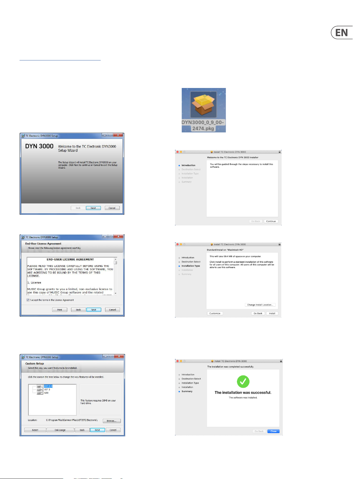
2.2 Installation on a Mac
Double click the installer (.pkg) le.
Proceed through the prompts to begin installation.
Accept the license agreement and click ‘Next’.
Select which VST and/or AAX components you want to install. Pro Tools uses
AAX and most other DAW programs use VST. The installer will oer a default
location to save the le, but you can choose another location by clicking
the ‘Browse’ button.
Click ‘Continue.'
A default location will be selected for installation, or you can select another
folder manually. If you have administrator authorization in place, you will need to
enter your password before beginning installation.
Click 'Close' when done.
Click ‘Next ’ to begin the installation. When installation is complete, click ‘Finish’.
Page 6
6 DYN 3000 User Manual
3. Activate your DYN 3000 iLok license
3.1 Activation when you have purchased the NATIVE version
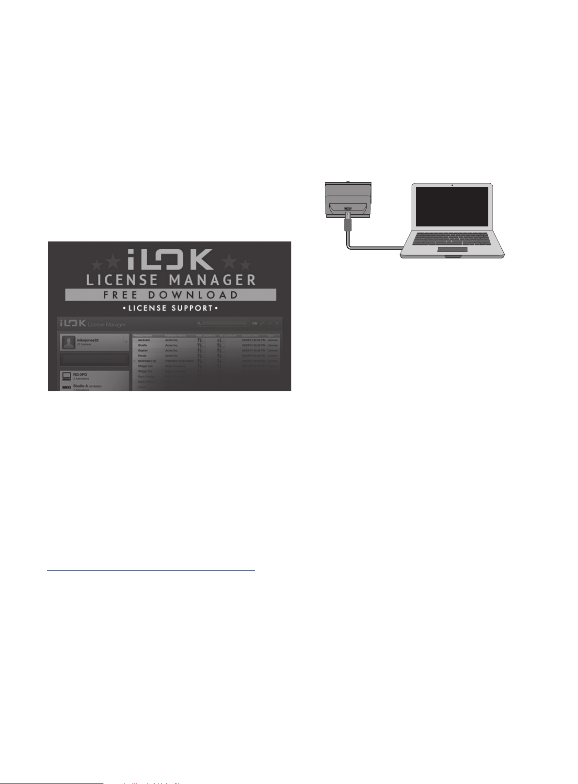
Step 1: Install iLok
The rst step is to create an iLok user account at www.iLok.com and install the
PACE iLok License Manager on your computer if it’s your rst time using iLok.
Step 2: Activation
In the received mail (when buying the NATIVE version) or on the rear cover of the
printed quick start guide (when you have bought the DT Desktop Controller
version) you will nd your personal Activation Code. To activate your software,
please use the "Redeem an Activation Code" feature in the PACE iLok License
Manager.
3.2 Get a Free Demo License
Make use of this hassle-free oer to try out our plug-ins before you buy.
• 14-Day Trial Period
• Fully Functional
• No Feature Limitations
• No Physical iLok Key Needed
4. Connection and Setup
4.1 Connecting the DYN 3000-DT Desktop Controller (optional)
Getting the Desktop Controller up and running couldn’t get any easier. Plug the
included USB cable into the unit ’s rear micro-USB port, and connect the other end
to a free USB port on your computer. The Desktop Controller is bus powered, so no
other power cables are necessary, and no additional drivers need to be
manually installed.
DYN 3000-DT
Laptop
The Desktop Controller will light up upon successful connection. You can now
apply the plug-in to a channel in your DAW to begin using the eect. This process
may vary slightly depending on your software, but generally should require
these steps:
• Select a channel or bus in your DAW to which you would like to add the eect.
Access the mixer page where you should see a section dedicated to eect slots
• Open the menu where you can select from a list of eect types, which
probably includes many stock plugins that are included with the DAW.
There should be submenu to view general VST/AU/AAX options.
• The plug-in will likely be found in a dedicated TC Electronic folder. Select the
DYN 3000 and it will now be added to the signal chain.
Double-click on the eect slot that contains the DYN 3000 to view the plug-in UI.
There should be a green link icon at the bottom, and text that indicates successful
connection between the plug-in and the Desktop Controller.
Step 1: Install iLok
The rst step is to create a free iLok user account at www.iLok.com and install the
PACE iLok License Manager on your computer if it is your rst time using iLok.
Step 2: Get your free license
Go to:
www.tcelectronic.com/brand/tcelectronic/free-trial-dyn3000-native
and enter your iLok User ID.
Step 3: Activation
Activate your software in the PACE iLok License Manager.
Page 7
7 DYN 3000 User Manual
4.2 Operating the DYN 3000
After you have installed the plug-in, activated the iLok license, and optionally
connected the DYN 3000-DT Desktop Controller via USB, you can begin inserting
the plug-in to your tracks.
Adjustments to the eect are done in two ways. Either by using the plug-in user
interface or by using the physical Desktop Controller.
4.5 Plug-in and Hardware Controls
After you have installed the plug-in, activated the iLok license, and optionally
connected the DYN 3000-DT desktop controller hardware unit via USB, you can
begin using it.
The controls of the plug-in and desktop controller are described in more detail
later in this manual.
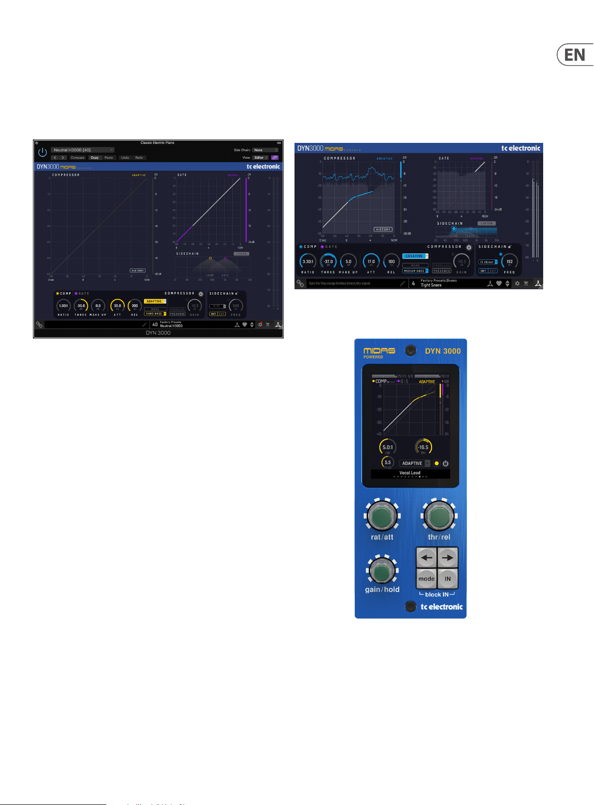
Plug-in User Interface:
Optional Desktop Controller Hardware Unit:
4.3 Insert vs Aux Eect
The DYN 3000 is intended for insertion directly into an eect slot on a single
channel, sub mix bus or master bus, which passes the entire signal through the
eect.
Be careful if using DYN 3000 on an auxiliary bus, as mixing the output of DYN
3000 with the original track sound will potentially create a phasing issue
depending on your DAW's ability to correc tly compensate for latency in plug-ins.
4.4 Mono/Stereo Operation
The DYN 3000 is intended for Mono and Stereo use for both channel, submix bus
and master bus operation.
For a Mono channel, the output signal is made by outputting the lef t plug-in
channel only.
The DYN 3000 has separate sidechains for the compressor and the gate. Both can
either be fed internally, or from the external input set up in the DAW.
Page 8
8 DYN 3000 User Manual
4.6 Connection Status to the Hardware Unit
The TC Icon family all use the same method to show the connection status
between the plug-in and the hardware unit.
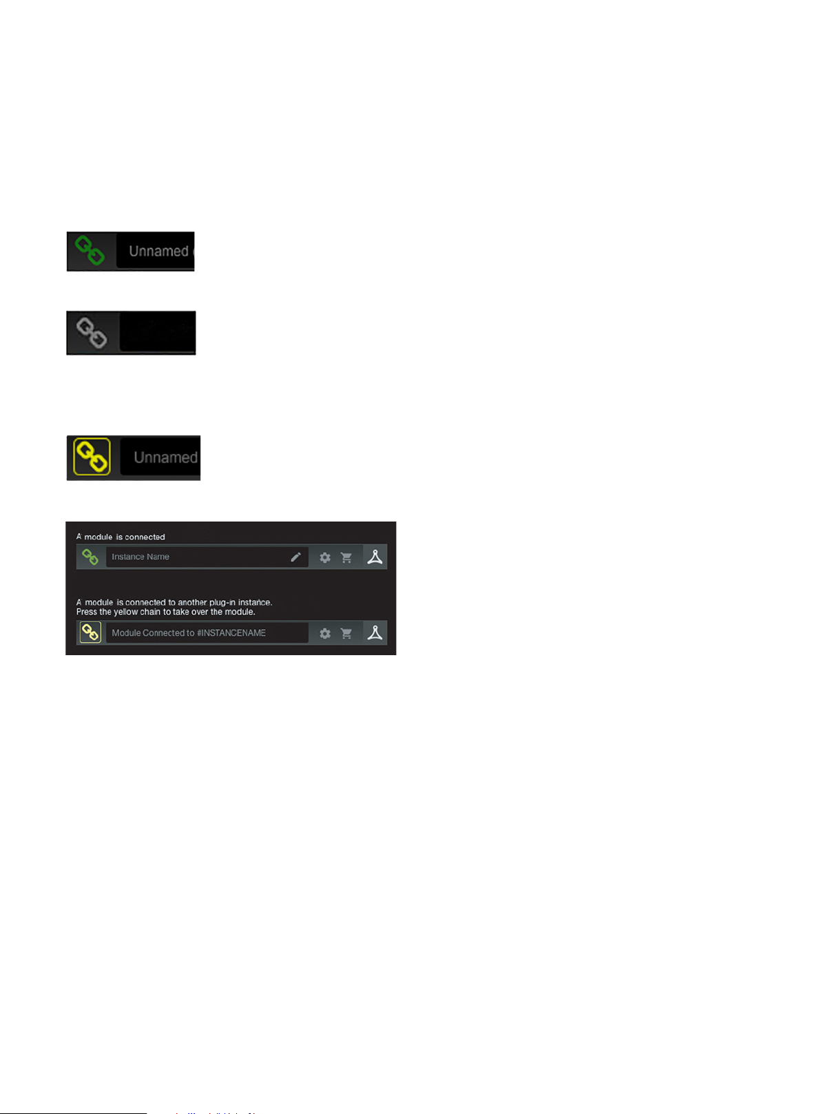
Connection status is indicated on the lower left side of the plug-in window.
Successful connec tion is indicated with a green chain icon. The Tooltips area will
show the plug-in instance name that the hardware unit is currently connected
to. This is often the DAW channel name. If your DAW does not support this, you
may enter a name for the instance. This may be especially convenient when using
DAW project templates.
When using the NATIVE version only, this chain icon will remain grey:
If another instance of the plug-in already exists on another track, the chain icon
will appear yellow, and the text box will notify you where the plug-in is currently
active. Click the chain icon to connect the hardware unit to the new plug-in
location.
To summarize the connection status possibilities:
Most DAWs oer the ability to move or drag plug-ins from one track/bus to
another, and DYN 3000 supports this as well.
Most DAWs also feature an on/o switch for plug-ins, accessible inside the
plug-in window and/or the track itself. Muting the plug-in will make the eect
inaudible, but will not shut down the connection to the hardware unit.
Page 9
9 DYN 3000 User Manual
5. User Interface
The DYN 3000 is controlled using the plug-in, or by using the optional hardware
unit (when you have purchased the DT version).
Overview
The DYN 3000 includes the following features:
• • Compressor and Gate
• • Mono and Stereo use for both channel, submix bus and master bus
operation
• • 4 content and use-dedicated compressor types: Adaptive, Corrective,
Creative and Vintage
• • 3 individual Gate types: Normal, Transient, and Ducker
• • Presence function and Parallel compression
• • Flexible sidechain lter with internal and external input
• • Scrolling History for signal and gain reduction overview
• • Constant-Q Real-Time Analyzer for sidechannel investigation
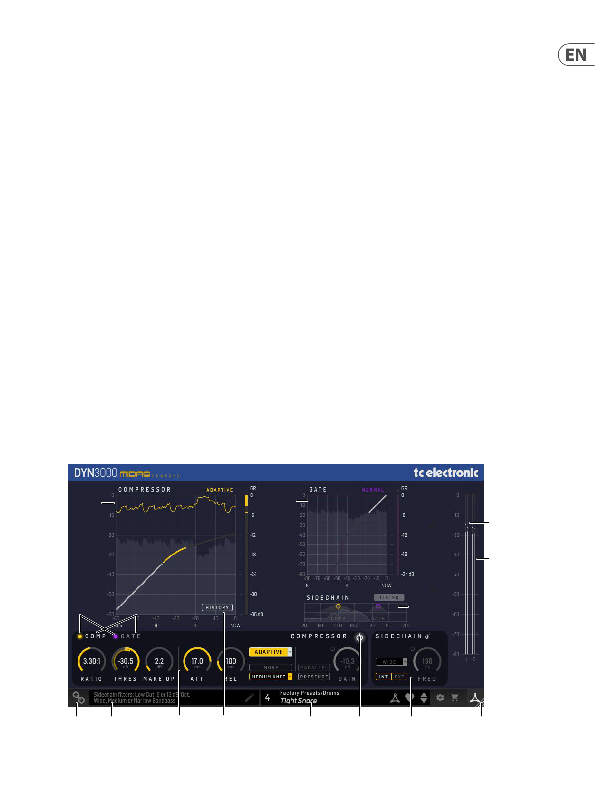
Main View
The DYN 3000 consists of ve elements; the input/output PPM at the right, the
controls section at the bottom, the main view with Compressor and Gate static
gain responses, gain reduction meters, and the sidechain view.
• • Sidechain lter views and Real-Time signal Spectrum
• • Scrolling History can be enabled/disabled
• • LISTEN outputs the sidechain signal of either the compressor or the gate
• • Note: All details are greyed out in the display when the DYN 3000 is
bypassed
Controls section
The controls section is where all the relevant parameters are located.
• • Enable/disable Compressor or Gate by clicking the enable button/LED in
the controls section
• • Access the Compressor or Gate controls by using the headline/panes in
the controls section or by clicking the lter handles in the sidechain view
• • Adjust all controls of the Compressor and the Gate to your liking using
the dials and buttons in the controls section
• • The Parallel compression or Presence function is enabled using the
enable button/LED. This is also great for A/B’ing the function
Sidechain Section
• • There are two sidechain lter controls sections, one for the compressor
and one for the gate. The view follows what is viewed in the left
controls section. If the left section is showing the compressor main
controls, then the sidechain will also show its compressor lter controls
• • Input/output PPM meters, 0 to -80 dB dBFS, +0 dBFS indication at the
top
• • Compressor static gain response, 0 to -60 dBFS, 12 second scrolling
sidechain signal history, and gain reduction meter, 0 to -36 dB
• • Gate static gain response, 0 to -80 dBFS, 8 second scrolling sidechain
signal history, and gain reduction meter, 0 to -24 dB
Compressor
Display
In/Bypass
Show Comp/Gate
Gate
Display
• • Enable/disable the sidechain lter for either the compressor or gate by
clicking the enable but ton/LED next to the FREQ dial
• • Adjust the frequency either by dragging the sidechain lter "handle" or
by using the FREQ dial in the sidechain controls section
• • Adjust the sidechain lter width/slope using Command + drag (Mac) /
Ctrl + drag (Win) on the lter handle, or by using the selection button in
the sidechain controls section
Input
Meter
L/R
Output
Meter
L/R
Sidechain
Display
Connection
Status
Tool Tips
Compressor/Gate
Controls
HistoryModule
Preset
Window
In/Bypass
Sidechain
Controls
Window Size
Adjustment
Page 10
10 DYN 3000 User Manual
At the right hand edge:
• • Input meters and Output meters with peak indicators
At the bottom left:
• • Connection status "Chain" icon
• • Connection status message and Tool Tips
At the bottom middle/right:
• • Preset number, preset name, factory or user, favorite, preset up/down
• • Setup
• • Shopping cart
At the bottom right corner:
• • User Interface size adjustment
The controls and features are described in more detail below.
5.1 In/Bypass and Gate/Compressor on/o
Press the In/Bypass button to bypass or engage the DYN 3000. This makes it easy
for you to listen and compare the overall eect of your work.
The Compressor and Gate may be turned on and o using their On/O buttons as
shown below. Click on the adjacent text to show the compressor or gate controls.
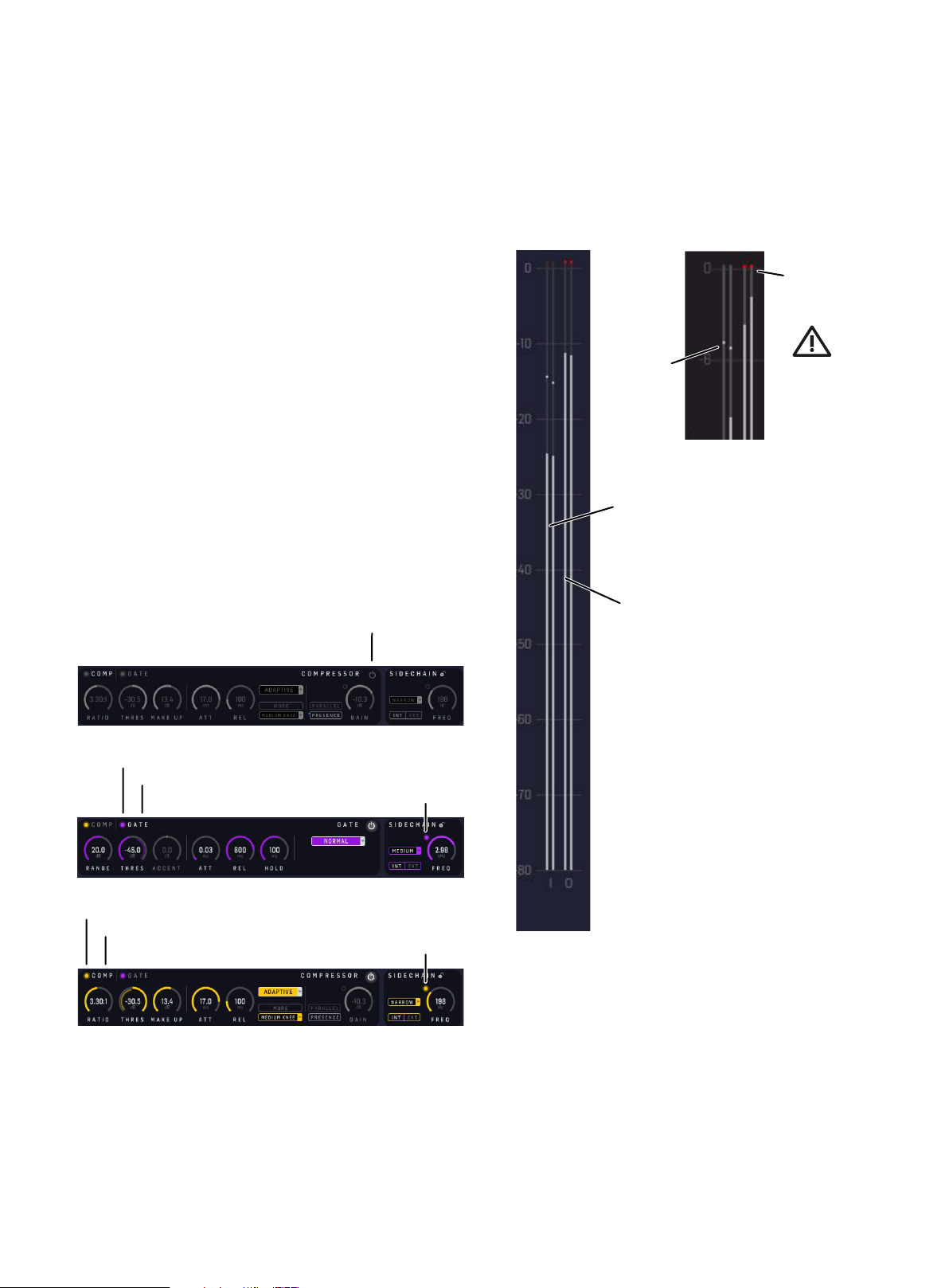
5.2 Meters
The PPM meters (Peak Program Meters) at the far right include a very accurate
Peak-Hold function.
CAUTION: You must ensure that no peaks exceed 0dBFS. These peaks will be
shown in red for a short time, before decaying. Keep an eye on them, and do
something about it if you see them.
Peaks have
reached
maximum
Peaks
Enlarged view of the
top of the meter
Input L/R
The sidechain view also has individual on/o buttons for the gate and
compressor lters.
In/Bypass
Gate On/O
Gate controls show
Sidechain Gate on/o
Compressor On/O
Compressor controls show
Sidechain Comp on/o
Output
Page 11

11 DYN 3000 User Manual
5.3 The DYN 3000 Compressor
The DYN 3000 is divided into two dynamic processor blocks: the compressor and
gate. The GUI treats both blocks independently, highlighted by dierent colored
controls: Purple for gate settings, and yellow, green, blue, or orange for compressor settings (depending on the compressor type).
Swapping between the compressor and gate can be done using the headline/
panes in the controls section, or by clicking the lter handles in the sidechain view.
The sidechain features a swept band-pass lter, or a low-cut lter, which acts on
the dynamic’s sidechain of the compressor, and which covers the full audio spectrum. The sidechain LISTEN button, outputs the ltered sidechain signal, allowing
the audio signal to be monitored.
Tip: Try compressing a bass guitar using a bass drum signal to trigger the sidechain
of the compressor using the external sidechain input and signal routing in the
DAW. This will let the bass drum cut through a mix a little more.
Parameters
• • Enable button/LED - enables the compressor block in the signal path.
When switched o, compressor is bypassed. (Both the comp and gate
switches can be on at the same time.)
• • Threshold - sets the signal level above which gain reduction starts to be
applied. Range is from 0 dBFS to -60 dBFS
• • Ratio - adjusts amount of compression applied to signals above
threshold. Range is from innity 1:1 to INF:1. When set to 10:1 or higher,
the compressor acts somewhat as a limiter
• • Attack - adjusts the time for the compressor to respond after an over-
threshold signal. Range is from 0.2 ms to 40 ms
• • Release - adjusts the time for compressor to recover after program
material falls back below threshold. Range is from 0.05 s to 3.00 s
• • Make-up gain - compensates for the reduced loudness of a compressed
signal. Range is 0dB to +24dB
• • Envelope Mode selection - selects compressor type. There are four
compressor types available: Corrective, Adaptive, Creative and Vintage
• • Knee Type - switches between three types of Knee settings, and this
controls how the compressor starts to apply gain as the signal goes
through the threshold. See Knee (below) for a description of the t ypes
• • MORE - adds to the legendary Midas sound set by the other settings
including Envelope Mode (Compressor Type) in an unique and
balanced way
• • Parallel/Presence Enable button/LED - enables Presence or Parallel
compression
• • Presence button - presence feature. Brings presence back after heavy
compression. The direc t/dry signal is frequency range limited
• • Parallel button - parallel/upward compression. The direct/dry signal is
full frequency range
• • Presence Gain - gain for the frequency range limited (presence) direct/
dry signal. Range is from -30 dB to -3 dB
• • Parallel Mix - wet/dry balance in parallel/upward compression.
Direct/dry signal is full frequency range. Range is from 0
(dry, fully uncompressed) to 100% (wet, fully compressed)
SIdechain Parameters
• • Sidechain Int/Ext - selects internal or external (from DAW) sidechain
• • Sidechain Filter Enable button/LED - enables compressor sidechain lter
• • Sidechain lter type - select from: Low-cut lter: 6 or 12 dB/Octave.
Band-pass lter: Wide, medium, or narrow (2, 1, and 0.3 Octave)
• • Sidechain lter frequency - adjusts the sidechain lter frequency in the
range 50 Hz to 15 kHz. (Visually, this moves the lter envelope on the
graph left or right, rather like a spotlight on the RTA.)
• • Sidechain Listen - to aid set up, the compressor has a sidechain
Listen function that sends the ltered sidechain signal to the output.
The Listen button illuminates to warn you that soloed material is from
the ltered sidechain, and not the program channel
Compressor
Display
Gate
Display
Sidechain
Display
Sidechain
Controls
Compressor Controls
Page 12

12 DYN 3000 User Manual
5.3.1 Threshold
The threshold adjusts the operating point of the compressor. Signals that go over
this point, or over-threshold, will be aected by compressor action. Signals that
stay below threshold will not trigger any compression although they may still be
aected by compression releases from previous over-threshold signals.
Note: The Threshold control has a helpful display of the signal level on the inner
ring, and the Threshold level on the outer ring. A highlighted overlap area on the
inner ring indicates the amount of compressor action, where the input signal
exceeds the Threshold level.
Threshold
Threshold
Signal level
Highlighted
Overlap Area
5.3.4 Release
The release control adjusts the time the compressor takes to recover after the
program material falls back below threshold. Both attack and release also respond
to changes in program level that remain over-threshold. For example, a signal that
reduces in level but remains above threshold will still trigger a release, but in this
case it will only be a partial release - because the compressor will still be required
to generate gain reduction, but now, as appropriate for the new lower signal level.
Release Time
5.3.5 Knee
Most compression sounds more natural in soft knee mode. Soft knee compression blurs the distinction between over-threshold and under-threshold signals,
such that signals that are a long way below threshold remain unaected by
compression, and signals that near the threshold get compressed, but at greatly
reduced ratios. When signals are just over-threshold the compressor ratios are still
somewhat reduced; it is only when signals go well over threshold that the full
ratio compression is applied. When using a harder knee setting, the compressors
operate in a more clinical way with a more dened transition between underthreshold and over-threshold; this is better suited to limiting style compression.
5.3.2 Ratio
The compression ratio control provides control of the amount of compression
that is applied to over-threshold signals. This is expressed as a ratio of signal level
changes from input to output. For example, when the compressor is set to 2:1,
every 2 dB of input level change will only generate a 1 dB output level change
(assuming the signal levels are over the threshold).
Ratio
5.3.3 Attack
The attack control adjusts the time taken for the compressor to respond to an
over-threshold signal. The shape of the attack can be selected from one of the four
mode combinations mentioned above, making the compressor easily adaptable
for a wide number of creative and corrective applications.
Knee Selection
5.3.6 Make Up Gain
The gain control provides adjustment of the make up gain so that the level of
the outgoing compressed signal can be matched to the incoming uncompressed
signal.
Make Up Gain
Attack Time
Page 13

13 DYN 3000 User Manual
5.3.7 Sidechain Filter
A low-cut lter and band-pass lter are provided to act on the sidechain signals.
This can be used to make the compression frequency-selective.
Compressor Filter
Filter
Type
ListenRTA
Internal or
External Source
Frequency
Engage/Disengage the Sidechain Filter
To engage or disengage the sidechain compressor lter, either double-click on
the compressor handle in the graph, or click on the small button next to the FREQ
control. Without the sidechain, the compression is triggered by the full-frequency
range of the source, rather than a ltered frequency section of it.
Click on the small Lock and the sidechain control settings will not change when a
new preset is chosen.
Sidechain Compressor Filter Engaged
Lock
Engage
The controls are as follows:
• • Frequency, adjustable from 25 Hz to 15 kHz
• • Band-pass bandwidth selectable: wide, medium, or narrow (2, 1, or 0.3
Oc taves)
• • Low-Cut selectable: 6 dB or 12 dB/Octave
• • LISTEN: This sends the ltered sidechain to the output, so you can
audition the eec t of the lter controls on the sidechain source
• • INT/EXT: The sidechain source can be internal, or an external source. The
output from other tracks can be added to the sidechain inputs of the
DYN 3000, using the Setup procedures in most DAWs
Note: The Low-Cut sidechain lter is often used with success on a full range mix
signal, so the full-range compressor does not react as much on low frequency
energy.
Note: The Real-Time Analyzer signal and the LISTEN function follow which of the
Compressor and Gate blocks are selected and shown in the controls
Sidechain Compressor Filter Disengaged
Low-Cut Examples
12 dB/Octave
6 dB/Octave
Page 14

14 DYN 3000 User Manual
Band-Pass Examples
Wide
Medium
Narrow
EXT: External Source, the DYN 3000 compressor will be triggered by the levels of a
dierent track than the plug-in is applied to. The selection of the external source
for the sidechain is set using your DAW. The compressor will still aect the track
that the plug-in is applied to, but it will be triggered by the audio of the external
source. Its eect will depend upon the settings of the sidechain lter, such as its
bandwidth, or low cut slope, and the frequency.
Sidechain Source = External
External Source’s
RTA
External Source
The rst DAW example below shows a typical method of choosing a sidechain
external source from a drop-down list of the currently-loaded tracks in your DAW
session.
Sidechain Internal and External Source
The sidechain source can be internal, or an external source. Once this is set up in
your DAW, you can quickly switch between INT or EXT.
Click on the INT or EXT buttons in the sidechain control section to choose the
source.
INT: Internal Source, the DYN 3000 compressor will be triggered by the levels of
the track the plug-in is applied to. Its eect will depend upon the settings of the
sidechain lter, such as its bandwidth, or low cut slope, and the frequency.
Sidechain Source = Internal
Internal Source
RTA
The selected track here is called “Main Bass.” As the track plays, the RTA will show
the “Main Bass” analysis, and you can press LISTEN to audition it as you adjust the
sidechain lter controls.
The second example shows another DAW, and the drop-down list of current tracks
to choose from.
Choose “none” or “no input” if an external source is not used, or just select INT in
the sidechain controls of the DYN 3000 GUI.
Typical DAW method of choosing a sidechain source:
Another DAW method of choosing a sidechain source:
Internal Source
Page 15

15 DYN 3000 User Manual
Sidechain Real-Time Analyzer (RTA)
The Real-Time Analyzer in the sidechains of the DYN 3000 is an informative version
of well-known and popular spectrum analyzers. This does not mean that we present more information than you need, which is often seen with popular analyzers
on the market where the spectrum in the high frequencies nearly looks like ‘grass’.
In the same analyzers, there is often little useful low frequency information to
benet from.
In the DYN 3000, we have gone a good step further to nd the right and mostuseful information for the delicate and sometimes dicult task of tuning the
sidechain lter in a compressor or gate.
The DYN 3000 features a Constant-Q Real-Time Analyzer showing a combined
peak and RMS spectrum. This will help you view both transients, and the slowermoving average spectrum.
The vertical y-axis covers the range from -60 to 0 dBFS. Note that a correlated
stereo signal such as a sinewave for example will measure up to 6 dB higher than
an uncorrelated signal.
Set your source playing, and the RTA will appear in the sidechain display. Note:
it will appear, even if the HISTORY button is not on. The RTA will help you decide
upon the best placing of your lter, and the best type of lter to select.
(In the example below, the gate and compressor lters have been disabled, just so
you can see the RTA graph more clearly.)
Sidechain RTA
5.3.8 Presence and Parallel Compression
Enable the Presence and Parallel Compression by pressing the small button/LED in
the right side of the compressor controls section.
Parallel/Presence
Disabled
Enabled
Presence
When applying compression either as a corrective or an artistic touch, you often
loose a bit of presence. That is why Midas has invented the clever and famous trick
on the biggest mixing consoles: the Presence feature. It allows a selected and netuned frequency range around 5 kHz of the untouched input signal to be passed
by the compressor and added to the compressed output signal, bringing back
some of the potentially lost presence. This way you can decide whether to go extra
gentle on sensitive content or go a bit harder in an artistic approach.
• • Enable the Presence and Parallel Compression and select Presence
• • Adjust the Presence GAIN control for the frequency range limited
(presence) direct/dry signal
Presence
Level
Frequency
Sidechain Key Commands, for smooth navigation
The following details will help you adjust the sidechain lter controls:
• • Enable/disable lter: Double-click handle (Mac/Win)
• • Change frequency: Mouse drag (no modier key) (Mac/Win)
• • Change width/slope: Command + drag (Mac) / Ctrl + drag (Win)
Presence
Gain
Presence Adjustment Example
For an example, when the Compressor gain reduction meter sits around -9 dB,
then adjusting the Presence GAIN to -9 dB will make the compressed signal and
the non-compressed “presence” signal approximately equally-leveled.
Gain Reduction Meter
approx. -9 dB
Presence
Gain
set to
-9 dB
Page 16

16 DYN 3000 User Manual
Parallel Compression
Parallel, upward, or New York compression is a widely used and great-sounding
compression technique.
The Dry signal is mixed with the Compressed signal, and the two signals are timealigned perfectly within the DYN 3000, eliminating any potential phase issues.
This is something that can be a challenge in some DAWs, and it makes the DYN
3000 perfectly suited for placing as an insert on either a channel, a sub-mix bus or
the master bus output.
Parallel compression reduces the dynamic range of your content by bringing up
the softest parts, enhancing the details while preserving the transients.
Sometimes, upward and downward (disable Parallel) compression is used in series
for less audible “compression” or for really “heavy compression.”
• • Enable the Presence and Parallel Compression and select Parallel
• • Use the MIX control to adjust the compressed (wet) and the non-
compressed (dry) signal balance in the parallel/upward compression to
your liking
Parallel
5.3.9 Compressor Type - the Envelope Modes
The four envelope modes, or signatures, are the key to the sonic character of
the DYN 3000 compressor, and they allow adjustment far beyond the normal
capabilities of simple attack and release settings. They largely fall into two
application types:
• • Corrective and Vintage: Compressors that are good at capturing and
controlling dynamic transients
• • Adaptive and Creative: Compressors that emphasise dynamic transients
and provide creative control of levels within a mix
Compressor Type Selection
The Vintage and Adaptive compressors tend to morph a little between these two
categories depending on threshold control settings. This makes them easy to use
intuitively with minimal ne-tuning of the envelope control settings.
Further renement and enhancement of the envelope modes is provided by
combination settings of the three-position KNEE switch. It is best to understand
the operation of these two functions in more depth before looking at the detail of
the compressor signature switching.
Parallel
Mix
Knee
The soft knee curves behave in a traditional way to blend the compression ratio
around the threshold setting (as described above), but more importantly they also
have a signicant eect on the attack envelope shapes. The soft knee typically
slows down attack speed on signals in the knee area, which is desirable for natural
sounding compression because it compliments the reduced ratio eect of the soft
knee. This produces very gentle compression in the knee region.
The KNEE switch has three settings: hard (4dB); medium (12dB): and soft (40dB).
In hard setting, the compressor still retains some soft knee characteristics. This
is because the implementation of an extremely hard knee produces undesirable
sounding distortion on low frequency program material.
Soft Knee
Soft Knee
Page 17

17 DYN 3000 User Manual
Medium Knee
Medium Knee
Adaptive Mode (exponential RMS - accurate)
This is a root-mean-square (RMS) sensing compressor with exponential attack and
release. The RMS averaging process interacts with the attack and release to produce a very adaptive envelope character. This allows faster attacks on large (overthreshold) signal changes and produces slower attacks on small signal changes,
regardless of attack time setting. It is also sonically accurate and works well for
both compression and limiting of vocals and many other sources. The attack control is still active, allowing some user intervention although the adaptive nature
makes envelope control setting fairly non-critical. The compressor is therefore very
fast and simple to set up on most program material. The most natural sounding
compression is normally achieved with soft knee settings.
Adaptive
Corrective Mode (exponential peak - fast)
This is a peak-sensing compressor (like many older designs) with exponential
attack and release. It produces aggressive compression that gives good fast
control/limiting of dynamic material. It can be used to add color to low frequency
signals, thus making it ideal for controlling extremely dynamic instruments like
bass guitar. The compressor tends to sound best with fast attack time settings that
capture transients and with release time adjusted to taste to either emphasise or
reduce distortion and pumping eects.
Hard Knee
Corrective
Creative Mode (linear peak - slow)
This is a peak-sensing compressor with linear (dB rate) attack and second order
release. The compressor is very transparent, providing some dynamic control but
without unduly aecting the intentional dynamic content of the source material.
The linear attack provides a constant rate of attack, such that large changes in
source signal level take longer to become compressed than smaller changes.
Adding soft knee noticeably delays these attacks, which can be particularly useful
on drums where compression can be applied to emphasise transients giving more
punch while retaining a good deal of artistic dynamic range from the drummer.
The compressor normally sounds best with slower attack time settings, when it
can be used on dicult instruments, such as the acoustic guitar, with relatively
fast release to keep equal perceived loudness within a mix without producing
excessive utter or distortion.
Hard Knee
Creative
Page 18

18 DYN 3000 User Manual
Vintage Mode (adaptive peak - bright)
This is a peak-sensing compressor with a partially adaptive nature. It produces
extremely subtle attack and release curves during the onset of compression that
are largely independent of the envelope control settings. However, as it is driven
harder, that is, signals are further over-threshold, the attack and release times become more aggressive and gradually return to manual control so that the operator
can optimise the capture (or otherwise) of larger transients etc. The peak sensing
algorithm intentionally increases harmonic overtones during compression, which
adds a tube or valve-like brightness and sparkle to the signal, producing extremely
natural and lively sounding compression of acoustic instruments.
Vintage
5.3.10 Compressor Graphs
The graphs below show the eect of adjusting the compressor’s parameters.
Ratio
This graph shows a signal on the compressor with ratio applied; it shows the point
of threshold and how ratio aects the gradient of the signal following this.
Knee
• • Hard knee compressor: Immediately applies gain reduction at the
selected ratio, once attack time has elapsed
• • Medium knee compressor: Intermediate knee type
• • Soft knee compressor, starting from before the threshold, it gradually
makes the transition to applying gain reduction at the selected ratio
Ratio = 1:1
The graph below shows an uncompressed signal, that is, with no ratio applied.
The Ratio is set to 1:1. It has a 1:1 gradient, where Input signal = Output signal,
and there is no eect on the audio.
Input=Output
Ratio = 1:1
Output Signal
Output Signal
Input=Output
Ratio = 1:1
• • Input level. The ‘x-axis’ of the graph
• • Output level. The ‘y-axis’ of the graph
• • The portion of the graph before the input Threshold level is unaected
Knee
Threshold
Ratio = slope
Input Signal
by compression, that is, the gradient is 1:1
Input=Output
Ratio = 1:1
Threshold
Input Signal
History
The History button enables a scrolling view of the potentially ltered sidechain
signal along with the gain reduction. This is an informative view of how the input
signal, the sidechain lter and the compressor settings will interact.
Scrolling
Display
• • Upper slope: The portion of the graph after the input Threshold
shows the eects of compression. The gradient is the same as the
compression ratio
• • Threshold is the point where the gradient changes and where
compression star ts to be applied
History
Now4 sec8 sec12 sec
Page 19

19 DYN 3000 User Manual
5.4 The DYN 3000 Gate
The second processor block in the DYN 3000 is the gate. It is shown in Purple for all
settings and processing views. Swapping between the gate and compressor blocks
can be done via the headline/panes in the controls section or via clicking the lter
handles in the sidechain view.
The sidechain lter features, just like for the compressor, a swept Band-Pass type
lter or a Low-Cut lter, which acts on the dynamic’s sidechain of the gate/ducker
and which covers the full audio spectrum. The sidechain Listen button outputs the
potentially ltered sidechain signal, allowing the audio signal to be monitored.
Parameters
• • Enable button/purple LED - enables the gate block in the signal path.
When switched o, gate is bypassed. (Both the comp and gate switches
can be on at the same time.)
Gate In/Bypass
Gate controls show
• • Threshold - sets the signal level at which the gate opens. Note: It is
opposite for the Ducker Gate mode. Range is from 0 dBFS to -80 dBFS
• • Range - adjusts the amount of gain reduction applied to the signal
below threshold. Controls the maximum gain reduction that is possible.
Range is from minus innity to 0 dB
In/Bypass
• • Accent (only available for Transient Gate mode) - sets the amount of
transient envelope accent applied to signal when crossing the threshold.
Range is from -6 dB to 6 dB
• • Attack - adjusts time taken for gate to open after an over-threshold
signal. Range is from 0.02 ms to 20 ms
• • Release - adjusts time taken for gate to close after program material
falls back below threshold. Range is from 2 ms to 2.0 s
• • Hold - Minimises chattering in conjunction with internal hysteresis.
Once the signal drops below the threshold, this denes a waiting period
before the gate starts to close. Range is from 2.0 ms to 2.0s
• • Gate Mode: Switch between Normal Gate, Transient Gate or Ducker
Sidechain Parameters
• • Sidechain Int/Ext - selects internal or external (from DAW) sidechain
• • Sidechain Filter Enable button/LED - enables gate sidechain lter
• • Sidechain lter type - selects sidechain lters: Low Cut, 6 or 12 dB/Oct.
Wide, Medium or Narrow Bell (0.3 Oct , 1 Oct and 2 Oct)
• • Sidechain lter frequency - adjusts the sidechain lter frequency in the
range 50 Hz to 15 kHz. (Visually, this moves the envelope on the graph
left or right.)
• • Sidechain Listen - to aid set up, the gate has a sidechain Listen function
that sends the potentially lteret sidechain signal to the output. The
Listen button illuminates to warn you that soloed material is from the
sidechain, and not the program channel
Compressor
Display
Gate
Display
Sidechain
Display
Sidechain
Controls
Gate Controls
Page 20

20 DYN 3000 User Manual
5. 4.1 Threshold
The threshold adjusts the operating point of the gate. Signals that go below this
point, or under-threshold, will be aected by gate action. Note: It is opposite for
the Ducker Gate mode.
Note that the Threshold control has a helpful display of the signal level on the inner ring, and the Threshold level on the outer ring. This display is dierent for the
Ducker Gate, compared to the Normal and Transient Gates.
A highlighted overlap area on the inner ring indicates the amount of gate action,
whenever the input signal drops below the Threshold level (or above, for the
Ducker gate).
Threshold
Normal and Transient Gates
Signal
Level
Highlighted
Overlap Area
Threshold
5.4.3 Accent
Accent is only available for Transient Gate mode. It sets the amount of transient
envelope accent applied to signal when crossing the threshold. The eect is not
unlike known gates that seem to overdo the transition from closed to open and
therefore has seen great use on especially percussive content like drums. Unlike
a normal gate, a higher threshold say around -30 dBFS may t the signal better.
High Accent settings may suit hard music styles well, and add great punch on the
drums. Settings below zero may sound similar to reduction of signal “attack” and
this is great for “tucking” a signal a bit further into the mix without touching levels
or EQ.
Accent (available for Transient Gate only)
5.4.4 Attack
Attack adjusts the time taken for gate to open after an over-threshold signal. For
percussive signals the attack should be set short, but for less percussive signals a
longer attack time will reduce the artefacts from the fast reacting processing.
Ducker Gate
Threshold
Highlighted
Overlap Area
Signal Level
5.4.2 Range
The range adjusts the amount of gain reduction applied to the signal below
threshold. Note: It is opposite for the Ducker Gate mode. It controls the maximum
gain reduction that is possible. The range is from minus innity to 0 dB.
Attack Time
5.4.5 Release
Release adjusts time taken for gate to close after program material falls back
below the threshold. Range is from 2 ms to 2.0 s. The optimal setting is often a
compromise between fast-enough-reacting noise reduction in the recording and
un-natural cut o of instrument sustain.
Release Time
5.4.6 Hold
Hold minimises chattering in conjunction with internal hysteresis that enables
unequal threshold for signals with increasing level, versus decreasing level. The
few-dB hysteresis often gives a more natural sounding gate operation. Once the
signal drops below the threshold, this denes a waiting period before the gate
starts to close.
Range
Hold Time
Page 21

21 DYN 3000 User Manual
5.4.7 Mode
There are three available Gate types that can be selected from the Mode dropdown menu.
Gate Type
• Normal
• Transient
• Ducker
• • Normal Gate - this is for standard noise and cross-talk gating tasks
• • Transient Gate - this is similar to the Normal gate but includes the
transient envelope accent, which is applied to the signal when crossing
the threshold. The eect is not unlike known gates that seem to overdo
the transition from closed to open, and therefore has seen great use on
especially percussive content like drums
• • Ducker - in radio this can typically be achieved by lowering (ducking) the
volume of a secondary audio track when the primary track starts and
lifting the volume again when the primary track is nished. A typical
use of this eect in a daily radio production routine is for creating a
voice-over. Use of the External sidechain allows the ducker on the
channel you wish to turn down, to be triggered by the channel you wish
to have priority (routed via the sidechain handling in the DAW)
The sidechain controls are as follows:
• • Frequency, adjustable from 25 Hz to 15 kHz
• • Band-pass bandwidth selectable: wide, medium, or narrow (2, 1, or
0.3 Oct aves)
• • Low-Cut selectable: 6 dB or 12 dB/Octave
• • LISTEN: This sends the ltered sidechain to the output, so you can
audition the eec t of the lter controls on the sidechain source
• • INT/EXT: The sidechain source can be internal, or an external source. The
output from other tracks can be added to the sidechain inputs of the
DYN 3000, using the Setup procedures in most DAWs
Note: The Real-Time Analyzer signal and the LISTEN function follow which of the
Compressor and Gate blocks are selected and shown in the controls.
Tip: For snare drum gating, try setting the width at 0.3 Octave and the frequency
around 2 kHz. This can help cut out spill from other close drums and give a cleaner
drum sound.
Snare bottom mics could also be triggered or keyed from the snare top mic (using
the DYN 3000 External sidechain input from the DAW) to allow the gate to open
faster and allow super quick transients through.
Sidechain Key Commands, for smooth navigation
The following details will help you adjust the sidechain gate lter controls:
5.4.8 Sidechain lter
A low-cut lter and band-pass lter are provided to act on the sidechain signals.
This can be used to make the gating function frequency-selective.
The sidechain lter controls for the gate are independent of those for the compressor, but they are otherwise identical in operation. Gate controls are always purple.
For more information regarding the sidechain lters and controls, please see the
details shown on page 13 and 14 for the compressor. See page 15 for details of the
sidechain RTA.
Note that for the Ducker Gate option, the sidechain’s external input is used. Please
see page 14 for details regarding how to set up the external input in a DAW.
RTA
Gate Filter
Listen
• • Enable/disable lter: Double-click handle (Mac/Win)
• • Change frequency: Mouse drag (no modier key) (Mac/Win)
• • Change width/slope: Command + drag (Mac) / Ctrl + drag (Win)
Filter
Type
Internal or
External Source
Frequency
Page 22

22 DYN 3000 User Manual
5.4.9 Gate Graphs
The graphs below show the eect of the gate threshold and range parameters.
Output=Input
Output Signal
Range
Input Signal
Threshold
Range and Threshold (Normal and Transient Gates)
Range and Threshold (Ducker Gate)
The Ducker gate works in the opposite way than the Normal gate or Transient gate.
The Ducker could also be considered a kind of two-state compressor (either
compressing or not), which can be useful in special cases and with some content.
Adjusting the timing parameters will soften the behaviour.
As an example, Duckers are often used in oce buildings, restaurants and other
installed sound applications, where background music is playing:
• • An announcement is made over the Tannoy
• • The background music is automatically reduced (ducked)
• • After the announcement, the background music reverts to its
original level
For the DYN 3000, the Ducker Gate is set up as shown in the example below:
• • Add the DYN 3000 plug-in onto a desired primary track
• • In the DAW, choose a secondary track to be the external input to the
gate sidechain. See page 14 for details of setting the sidechain external
source in a DAW
• • Set the gate sidechain to EXT (external source)
• • When the secondary track exceeds the Threshold level, then the primary
track will be reduced by the level set by the Range control
• • Input level: The horizontal ‘x-axis’ of the graph
• • Output level: The vertical ‘y-axis’ of the graph
• • Threshold: If the input signal level drops below the Threshold level, the
output level is reduced by a dB value set by the Range control
• • The Range is the amount of reduction added to the input level, when it
drops below the Threshold level
• • Lower slope: The portion of the graph before the Threshold is reduced in
level by a dB value set by the Range. The output is less than the input
• • Upper slope: The portion of the graph after the Threshold is not aected
by any gate controls, and the output equals the input
• • When the secondary track drops below the Threshold level, then the
primary track will revert to its original level
• • Press LISTEN to audition your secondary track and the eect of the
sidechain lter controls to choose the best settings
Output Signal
Range
Output=Input
Input Signal
Threshold
• • Input level (primary track): The horizontal ‘x-axis’ of the graph
• • Output level (primary track): The vertical ‘y-axis’ of the graph
• • Threshold: If the sidechain external input signal level (of the secondary
track) exceeds the Threshold level, the primary track's output level is
reduced by a dB value set by the Range control
• • The Range is the amount of reduction of the primary track
• • Lower slope: The portion of the graph before the Threshold is not
reduced in level. The output equals the input
Page 23

23 DYN 3000 User Manual
• • Upper slope: The portion of the graph after the Threshold shows that
the primary track is reduced by the amount set by the Range control,
allowing the secondary track to be heard
5. 4.10 History
The History button in the lower right of the compressor graph display enables a
scrolling view of the potentially ltered Gate sidechain signal along with the gain
reduction. This is an informative view of how the input signal, the sidechain lter
and the gate settings will interact.
Scrolling
Display
Listen
History
Now4 sec8 sec
Page 24

24 DYN 3000 User Manual
6. Navigating the DYN 3000 Desktop Controller (optional)
Display
Ratio/
Attack
Gain/
Hold
Threshold/
Release
Left
Right
In/
Bypass
Mode
Display
The DYN 3000 Compressor and Gate plug-in takes mixing audio to a new level,
especially when used in combination with the optional but highly dedicated
Desktop Controller. It adds intuitive and true analog feel user-controls, informative
compressor and gate views and sidechain displays right on your desk, without the
need for opening plug-in instances all the time. The DYN 3000 Desktop Controller is designed with focus on speeding up work ow, inspirational hands-on
experience, and letting you concentrate on the mix. It allows simultaneous display
and control of all the critical information required to craft an unprecedented mix
experience.
• • Input PPM, dBFS, 0 to -60 dBFS, with +0dBFS indicators
• • Output PPM, dBFS, 0 to -60 dBFS, with +0dBFS indicators
• • Gain reduction and static gain response views for Compressor and Gate
• • Real-Time Analyzer in the sidechain view
• • Controls section: Shows the selected compressor or gate controls, the
sidechain controls or global settings page
• • Page order: Four compressor pages, three gate pages, and a global
settings page
Dials and Buttons
Note: The dials and buttons have dierent actions depending on which page is
selected: One of four compressor pages, one of three gate pages or the global
settings page.
• • Ratio/Attack dial
• • Threshold/Release dial
Input Output
Page
Comp
graph
Ratio
Make Up
Gain
Current
Track
Page Indicators (enlarged view)
PPM Meters
Comp
Type
Comp In/
Bypass
Gain
Reduction
meters
Threshold
In/
Bypass
• • Gain/Hold dial
• • Arrow left/right buttons - selects the previous/next controls page of the
compressor and gate. The Global settings page is at the far right. See the
page order below
• • Hold the right arrow button to go straight to the Global settings page
• • Hold the left arrow button to return to the previous page
• • Mode button (selec ts various modes and types)
• • IN button (overall DYN 3000 IN/bypass toggle). Same behaviour on all
pages. All processing views are greyed out in the display when the DYN
3000 is bypassed
• • Block IN (hold Mode and IN) (IN/bypass toggle for the selected
compressor or gate block)
• • Hold the Mode button and turn the Gain/hold to select other plugin
instances (tracks), without the need for opening the plugins
Page Order
• • Note: The top left corner of the display shows the page indicators
• • Compressor page 1 to 3
• • Compressor sidechain (Comp page 4)
• • Gate page 1 and 2
• • Gate sidechain (Gate page 3)
Compressor Pages (4)
Gate Pages (3) Settings Page
• • Settings page
Page 25

25 DYN 3000 User Manual
Compressor InCompressor Mode
Page Order
6.1 Compressor Page 1
• • Ratio/Attack dial: Sets the compression Ratio. Range is from innity 1:1
to INF:1
• • Threshold/Release dial: Sets the compression Threshold. Range is from
0 dBFS to -60 dBFS
• • Gain/Hold dial: Sets the compression Make-Up gain. Range is 0dB to
+24 dB.
• • Mode button: Selects the compressor types, envelope modes: Adaptive,
Corrective, Creative, and Vintage
• • Block IN (Mode + IN): Enables/disables the Compressor block
Ratio
Threshold
6.2 Compressor Page 2
• • Ratio/Attack dial: Sets the compressor Attack time. Range is from 0.2 ms
to 40 ms
• • Threshold/Release dial: Sets the compressor Release time. Range is
from 0.05 s to 3.00 s
• • Gain/Hold dial: Selects the compressor Knee: Soft, Medium, Hard
• • Mode button: Toggles the compressor MORE function on/o
• • Block IN (Mode + IN): Enables/disables the Compressor block
Knee
Attack
Knee
Release
Make up
Gain
Compressor InMore
Page 26

26 DYN 3000 User Manual
6.3 Compressor Page 3
• • Ratio/Attack dial: Toggles the Presence function and Parallel
compression on/o
• • Threshold/Release dial: Sets the Presence Gain or Parallel compression
Mix parameter. Presence Gain range is from -30 dB to -3 dB. Parallel
Mix range is from 0 (dry, fully uncompressed) to 100% (wet, fully
compressed)
• • Gain/Hold dial: Selects Presence function or Parallel compression
• • Mode button: Selects the compressor types, envelope modes: Adaptive,
Corrective, Creative, and Vintage
• • Block IN (Mode + IN): Enables/disables the Compressor block
Parallel/
Presence
On/O
Parallel/
Presence
Mix
6.4 Compressor Sidechain Page 4
• • Ratio/Attack dial: Selects the compressor sidechain lter width/t ype.
Low Cut, 6 or 12 dB/Octave. Wide, Medium or Narrow Bell (2 Oct , 1 Oct
and 0.3 Oct)
• • Threshold/Release dial: Sets the compressor sidechain lter frequency.
Range is from 50 Hz to 15 kHz
• • Gain/Hold dial: Selects the compressor sidechain to source Internally or
Externally from the DAW
• • Mode button: Toggles compressor sidechain Listen on/o
• • Block IN (Mode + IN): Enables/disables the compressor Sidechain lter
Filter
Type
Int/Ext
Source
Frequency
Compressor InListen
Compressor InType
Page 27

27 DYN 3000 User Manual
6.5 Gate Page 1
• • Ratio/Attack dial: Sets the gate Range. Values from minus innity to 0 dB
• • Threshold/Release dial: Sets the gate Threshold. Range is from
0 dBFS to -80 dBFS
• • Gain/Hold dial: Sets the Transient gate Accent amount.
Range is from -6 dB to 6 dB
• • Mode button: Select gate mode: Normal Gate, Transient Gate, or Ducker
• • Block IN (Mode + IN): Enables/disables the Gate block
Range
Accent
Threshold
6.7 Gate Sidechain Page 3
• • Ratio/Attack dial: Sets the gate sidechain lter width/type. Low Cut, 6 or
12 dB/Octave. Wide, Medium, or Narrow Bell (2 Oct , 1 Oct and 0.3 Oct)
• • Threshold/Release dial: Sets the gate sidechain lter frequency Range is
form 50 Hz to 15 kHz
• • Gain/Hold dial: Selects the gate sidechain to source Internally or
Externally from the DAW
• • Mode button: Toggles gate sidechain Listen on/o
• • Block IN (Mode + IN): Enables/disables the gate Sidechain lter
Filter
Type
Frequency
Gate InGate Mode
6.6 Gate Page 2
• • Ratio/Attack dial: Sets the gate Attack time. Range is from
0.02 ms to 20 ms
• • Threshold/Release dial: Sets the gate Release time. Range is from
2 ms to 2.0 s
• • Gain/Hold dial: Sets the gate Hold time. Range is from 2.0 ms to 2.0s
• • Mode button: Select gate mode: Normal Gate, Transient Gate, or Ducker
• • Block IN (Mode + IN): Enables/disables the Gate block
Int/Ext
Source
Gate InListen
6.8 Settings Page
• • Ratio/Attack dial: Set brightness of the Desktop Controller display
• • Threshold/Release dial: Browse plug-in Presets
• • Gain/Hold dial: Select which track (plug-in instance) to connect the
Desktop Controller to. The Instance selection can also be done from any
page by holding the Mode button and turning the Gain/Hold knob
• • Mode button: Recall the selected preset
Attack
Hold
Release
Gate InGate Mode
Brightness
Current Track
Recall
Preset
Preset
Scroll
Page 28

28 DYN 3000 User Manual
7. Presets
The DYN 3000 oers a collection of factory presets, as well as the option to create
and save your own custom settings as user presets and favourites.
Note that most DAWs have a built-in preset function that appears on every plugin, which is often found at the top of the plug-in window.
It is not recommended to use this as your primary method of saving presets, as it
has limited functionality, and does not allow the saved presets to be transferred
easily to other DAWs. Instead, we suggest using the Preset section at the bottom
right area of the user interface window:
Factory Preset Name
Favorite Number
Factory Preset Logo
Assigned as Favorite
Browse Favorite Presets
The presets menu is divided into Factory Presets and User Presets:
7.1 Factory Presets
Factory presets are built into the plug-in and cannot be overwritten, so if a
factory preset is modied and you want to keep the changes, you need to save it
as a User preset. User presets can be edited and organized as you like.
When recalling a Factory preset or saved User preset, the name will appear in
plain text as shown below.
7. 2 User Presets
If you make an alteration to any of the parameters in the current preset, the
preset name changes to italics as a reminder that something has changed from
the original factory preset.
To save this new setting as a User preset, click in the PRESET window, then select
the Save As option. Save it with an appropriate name.
To discard the changes without saving, simply navigate away from that preset.
A single click on this PRESET window brings up a menu with several presetrelated options. You can recall a fac tory or user preset from the libraries, save the
current preset, or create a new user preset with the 'Save as' option.
The altered preset will be saved as a user preset, with your new name for it, and
its name will now appear in the presets window.
If you modify a saved user preset, you have the option to "Save" (rewriting over
the existing user preset) or "Save As" (save as a new user preset).
If you modify a factory preset, then only "Save As" is available (to save as a new
user preset). Factory presets cannot be overwritten.
User presets are not given a number unless you rst assign them as favorites.
(See Favorite Presets below.)
You can use your computer's keyboard to enter a specic preset number, followed
by the ENTER button.
Page 29

29 DYN 3000 User Manual
Preset
7. 3 Presets and the optional hardware unit
Presets can also be recalled from the hardware unit by navigating to the Global
Settings Page.
• • Hold the right arrow button to go straight to the Global Settings page
• • Use the Threshold/Release control to browse through the available
presets
• • Press the Mode button to recall and load that preset
• • Use the Gain/Hold control to select the plug-in instance (track) if you
have more than one DYN 3000 plug-in in your DAW session. The display
shows the current track name at the bottom
Brightness
Preset
Scroll
7.4 Favorite Presets
Creating your own presets will make them accessible from the Preset menu,
but they will only appear in the list of 100 presets in the plug-in or hardware unit
if you set them as a favorite. This is done by assigning a favorite slot number to
the preset using the Favorite menu.
Click the FAVORITE (heart-shaped) button in the preset window, then select one
of the 10 banks. Assign one of your custom presets to a favorite slot, then the
preset name will appear to the left of the preset name.
Current Track
Set Display
Brightness
Recall
Select which plug-in instance
(Track) to connect the
Desktop Controller
Browse
Presets
Left
Right
In/
Bypass
Recall
Selected
Preset
User Preset Name
Favorite Number
User Preset Logo
Assigned as Favorite
Browse Favorite Presets
When a preset is assigned a favorite slot number:
• • The preset is part of the 100 presets that can be recalled on the
hardware unit
• • The favorite number will be displayed on the hardware unit when
recalled
• • The favorite number will be locked so that two presets cannot be
assigned to the same favorite slot number. This is shown in the Favorite
menu by graying out the number in question
• • The favorite number will be displayed in brackets when you browse the
presets menu
You can remove the favorite assignment by clicking on the Heart again, and
selecting the “Remove Assignment” feature at the bottom line of the Favorite
menu.
Page 30

30 DYN 3000 User Manual
Browse Favorites Only
The 'Browse Favorites Only' option in the preset menu allows the UP/DOWN
arrows in the bottom bar of the plug-in, or via the hardware unit, to scroll only
through the favorites list. Otherwise, scrolling goes through all presets.
7.5 Make Current Preset Default
8. Software Updates
New versions of the sof tware may be released to add new features and improve
performance. Updates can be detected from the plug-in directly and can be
installed after download from the website. See Chapter 2 for plug-in installation.
If the ’Automatically check for updates’ option is checked inside the update
menu, the red dot will appear on the settings icon when a new plug-in
is available.
Click the gear icon and select “Check for Updates” to perform a scan.
Selecting 'Make current preset default' will cause this preset to appear every time
a new instance of the plug-in is created.
7.6 Reveal User Preset Folder in Explorer
To change the name of a preset, select 'Reveal User Preset Folder in Explorer'
and modify the le name. This will open a Finder (Mac) or Explorer (PC) window
where the user presets are stored. You can rename as well as delete, copy and
paste presets. This allows you to share presets with other users online, simply
pasting the new ones in this folder.
8.1 Hardware Unit Software Updates (optional)
The hardware unit rmware will be included in each plug-in update.
After you have installed a new plug-in, the system will detect mismatched
rmware and indicate a need for update via a small red dot on the gear icon.
Click the “Upgrade to x.x.xx” eld to start the update. Progress will be indicated
in the plug-in, and the Feedback LED on the hardware unit will ash. (This
example shows a TC2290 plug-in.)
Page 31

31 DYN 3000 User Manual
9. Specications
Sound
Processing Processing versatile compressor and
gate for channel, bus and master.
Presence function and parallel
compression. Flexible sidechain ltering
Operation Mono, stereo
Analysis Scrolling history and constant-Q real
time analyzer
Sample rates 44.1, 48, 88.2, 96, 176.4, 192 kHz
Software Support
Operating systems Mac OS X 10.13 Sierra or above,
Windows 7 or above
Drivers No additional drivers required,
uses standard USB HID drivers
Plugin formats AAX-native, Audio Units, VST2.4,
VST3. 64 bit
USB Connection (DT version)
Type USB 2.0, type micro-B
Power (DT version)
Power supply USB bus powered
Power consumption Max. 2.5 W
Physical (DT version)
Display 2.4 Inch, 240x320 pixel, color TFT
Controls High-resolution, true-analog feel,
endless potentiometers, and dedicated
buttons
Dimensions (HxWxD) 42 x 54 x 135 mm (1.7 x 2.1 x 5.3")
Weight 0.2 kg (0.44 lbs)
Page 32

32 DYN 3000 User Manual
FEDERAL COMMUNICATIONS
COMMISSION COMPLIANCE
INFORMATION
TC Electronic
DYN 3000-DT
Responsible Party Name: Music Tribe Commercial NV Inc.
Address: 901 Grier Drive
Las Vegas, NV 89118
USA
Phone Number: +1 747 237 5033
DYN 3000-DT
This equipment has been tested and found to comply with the limits for a Class B
digital device, pur suant to part 15 of the FCC Rules. These limits are designed
to provide reasonable protection against harmful interference in a residential
installation. This equipment generates, uses and can radiate radio frequency
energy and, if not installed and used in accordance with the instructions, may cause
harmful interference to radio communications. However, there is no guarantee that
interference will not occur in a particular installation. If this equipment does cause
harmful interference to radio or television reception, which can be determined
by turning the equipment o and on, the user is encouraged to try to correct the
interference by one or more of the following measures:
• • Reorient or relocate the receiving antenna.
• • Increase the separation between the equipment and receiver.
• • Connect the equipment into an outlet on a circuit dierent from that to which the
receiver is connected.
• • Consult the dealer or an experienced radio/TV technician for help.
This device complies with Part 15 of the FCC rules. Operation is subject to the
following two conditions:
(1) this device may not cause harmful interference, and
(2) this device must accept any inter ference received, including inter ference that may
cause undesired operation.
Important information:
Changes or modications to the equipment not expressly approved by Music Tribe
can void the user’s authority to use the equipment.
Page 33

 Loading...