

Page 1

SERVICE
MANUAL
Model SB25
Blended Ice Machine
Original Service Instructions
081218-S
8/12/14 (Original Publication)
(Updated 3/26/15)
Page 2

Page 3

Table of Contents
Section 1: Introduction 1...............................................
Safety 2.............................................................
SB25 Specifications 4.................................................
General Installation Instructions 6.......................................
Environmental Notices 8...............................................
Section 2: Controls and Systems 9......................................
Control Overview 10....................................................
Keypad 11............................................................
PC Connection 12......................................................
General Repairs 17....................................................
Blender Drive Board 30.................................................
Blender Pitcher Rinse Station 31.........................................
Blender Pitcher Rinse Station Repairs 32.................................
Section 3: Troubleshooting 37...........................................
General Troubleshooting 38.............................................
Rinse Station Troubleshooting 41........................................
Blender Troubleshooting 42.............................................
Section 4: Parts 45......................................................
Warranty Explanation 46................................................
Model SB25 Operator Parts 49..........................................
Model SB25 Internal Service Parts 51....................................
Model SB25 Drain Assembly 53.........................................
Model SB25 Front Panel 55.............................................
Model SB25 Manifold 082222-12 56......................................
Model SB25 Pump-Cane A. - X82356 57..................................
Rinse Station 58.......................................................
Table of Contents Model SB25
Page 4

Table of Contents - Page 2
Rinse Station Manifold 082222-05 59.....................................
Parts List 60...........................................................
Wiring Diagram 68.....................................................
CAUTION: Information in this manual is intended to be used by Taylor Authorized
Service Technicians only.
Note: Continuing research results in steady improvements; therefore,information
in this manual is subject to change without notice.
Note: Only instructions originating from the factory or its authorized translation
representative(s) are considered to be the original set of instructions.
E 2014 Carrier Commercial Refrigeration, Inc. (Original Publication)
(Updated March, 2015)
081218-S
Any unauthorized reproduction, disclosure, or distribution of copies by any person of any portion of this
work may be a violationof Copyright Law ofthe United States of America and other countries, could result
in the awarding of Statutory Damages of up to $250,000 (17 USC 504) for infringement, and may result
in further civil and criminal penalties. All rights reserved.
Taylor Company
a division of Carrier Commercial Refrigeration, Inc.
750 N. Blackhawk Blvd.
Rockton, IL 61072
Model SB25 Table of Contents
Page 5

Section 1: Introduction
S Safety
S Specifications
S General Installation Instructions
S Environmental Notices
Model SB25
1
Introduction
Page 6
Safety
______________________________
We at Taylor are committed to manufacturing safe
operating and serviceable equipment. The many
built-in safety features that are part of all Taylor®
equipment are aimed at protecting operators and
trained service technicians alike.
This manual is intended exclusively for
Taylor authorized service personnel.
DO NOT attempt to run the equipment
unless you have been properly trained to do so.
CAUTION: THIS EQUIPMENT MUST BE
PROPERLY GROUNDED! Do not operate this unit
unless it is properly grounded and all service panels
and access doors are restrained with screws. Failure
to do so can result in severe personal injury from
electrical shock!
S Appliances that are permanently connected
to fixed wiring and for which leakage
currents may exceed 10 mA, particularly
when disconnected, not used for long
periods, or during initial installation, shall
have protective devices such as a GFI to
protect against the leakage of current,
installed by authorized personnel to the local
codes.
S Supply cords used with this unit shall be
oil-resistant, sheathed flexible cable, not
lighter than ordinary polychloroprene or
other equivalent synthetic
elastomer-sheathed cord (Code designation
60245 IEC 57) installed with the proper cord
anchorage to relieve conductors from strain,
including twisting, at the terminals and
protect the insulation of the conductors from
abrasion.
If the supply cord is damaged, it must be
replaced by an authorized Taylor service
technician in order to avoid a hazard.
Failure to follow these instructions may result in
electrocution or damage to the unit.
S DO NOT attempt any repairs unless the
main power supply to the unit has been
disconnected.
S DO NOT operate the unit with larger fuses
than specified on the data label.
S Stationary appliances which are not
equipped with a power cord and a plug or
other device to disconnect the appliance
from the power source must have an all-pole
disconnecting device with a contact gap of
at least 3 mm installed in the external
installation.
DO NOT partially remove the ice hopper
cover. Complete removal of the hopper cover is
required when accessing the ice bin. Failure to
follow this instruction may result in personal injury.
DO NOT remove any internal operating
parts unless all control switches are in the OFF
position. Failure to follow these instructions may
result in severe personal injury from hazardous
moving parts.
Introduction
2
Model SB25
Page 7
THIS UNIT HAS MANY SHARP EDGES
THAT CAN CAUSE SEVERE INJURIES.
This unit must be installed on a level
surface to avoid the hazard of tipping. Extreme care
should be taken in moving this equipment for any
reason.
Two or more people are required to safely move this
unit. Failure to comply may result in personal injury
or equipment damage.
This appliance is only intended to be
installed in a location where its use and maintenance
is restricted to trained personnel.
This unit must NOT be installed in an area
where a water jet or hose can be used. NEVER use
a water jet or hose to rinse or clean this unit. Using a
water jet or hose on or around this equipment may
result in the electrocution of the user or damage to
the equipment.
Cleaning and sanitizing schedules are
governed by your state or local regulatory agencies
and must be followed accordingly. Please refer to
the cleaning section of the Operator Manual for the
proper procedure to clean this unit.
WARNING!
Some consumers are highly allergic to
strawberries. In some severe cases, allergic
reactions to strawberries can cause death.
When blending natural strawberry
products, make sure excess product is
removed from the pitcher to eliminate
product carryover.
Model SB25
3
Introduction
Page 8
SB25 Specifications
The Model SB25 is a combination unit consisting of
the Model SB24 commercial ice shaver/blender unit
and a rinse station.
The Model SB24 shaver/blender unit has the option
of metered water and liquid sugar cane dispensing.
The rinse station is a timer controlled, automatic
system that rinses the interior of the blender
pitchers.
Ice Hopper
The standard frosted ice hopper holds approximately
28 lbs (13 kg) of ice. An optional clear ice hopper is
available which holds approximately 15 lbs (7 kg) of
ice.
Blender Pitcher
The maximum fill capacity of the blender pitcher is
48 fl oz (1.4 liters).
Electrical
Two dedicated electrical connection are required for
the SB24 and X81173-12. See the electrical chart
for proper electrical requirements. Manufactured to
be cord connected. Cord length is 9 ft. (274 mm)
external to unit.
Blender Station
Electrical Total Amps
115/60/1 10.0A 5-15P
Supplied with
NEMA Cord
Water
A 3/8” (9.5 mm) water line with minimum 55 PSI
(380 kPa) is required.
INSTALL POTABLE WATER CONNECTION
WITH ADEQUATE BACK-FLOW
PROTECTION TO COMPLY WITH
APPLICABLE NATIONAL, STATE AND
LOCAL CODES. WATER TEMPERATURE IS
NOT TO EXCEED 125°F (51°C).
Drain
A drain is required. The drain must be able to
accommodate a 1-1/8” (29 mm) diameter drain tube.
A minimum of 1” (25 mm) air gap is required
between the end of the drain tube and the drain to
ensure proper flow.
IMPORTANT: The unit must be installed on a level
surface for proper drainage.
Accessories include 10 ft. (3050 mm) of 7/8” (222
mm) ID drain hose.
Air Cooled
No additional clearance is required on either side of
the unit for air inlet or discharge.
2” (50 mm) of clearance is required behind the unit
to allow for proper routing of the drainage hardware.
12” (304 mm) of air clearance is required above the
unit to allow for proper loading of ice into the ice
hopper.
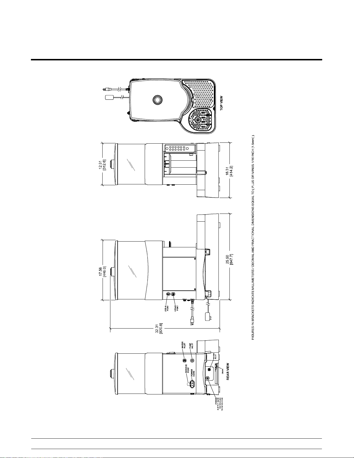
Dimensions
Width: 12-1/4” (311 mm)
Depth: 18” (457 mm)
Height:23-1/2” (597 mm)
Rinse Station
Electrical Total Amps Power Supply
24 VAC 0.63A 115V
This unit may be manufactured with other electrical
characteristics. Refer to the local Taylor Distributor
for availability. (For exact electrical information,
always refer to the data label of the unit.)
Introduction
Approximate Weights
Net: 35 lb (15.9 kgs)
Crated: Carton #1 35 lbs. (15.9 kgs)
Carton #2 11 lbs. (5 kgs)
Water Pressure
55 PSI (380 kPa) minimum incoming
100 PSI (690 kPa) maximum incoming
4
Model SB25
Page 9
SB25 Specifications (Continued)
Model SB25
5
Introduction
Page 10

General Installation Instructions
CAUTION: Only trained, authorized service
technicians should install the Blended Ice Machine.
Failure to comply will void the factory warranty.
The following are general installation instructions.
For complete installation instructions, please see the
Installation Checklist.
ALL WIRING AND PLUMBING MUST
CONFORM TO NATIONAL AND LOCAL CODES.
INSTALL POTABLE WATER CONNECTION
WITH ADEQUATE BACK-FLOW
PROTECTION TO COMPLY WITH
APPLICABLE NATIONAL, STATE AND
LOCAL CODES.
This unit must be installed on a level
surface to avoid the hazard of tipping. Extreme care
should be taken in moving this equipment for any
reason.
Two or more people are required to safely move this
unit. Failure to comply may result in personal injury
or equipment damage.
Uncrate the unit. Inspect the unit for damage. Report
any damage to the Taylor Factory immediately.
This unit is made using USA sizes of hardware. All
metric conversions are approximate.
Air Clearance:
Site Preparation
Review the area where the unit will be installed
before uncrating the unit. Make sure that all possible
hazards to the installer, user, and the unit have been
addressed.
For Indoor Use Only: This unit is designed to
operate indoors, under normal ambient
temperatures of 70° - 75°F (21° - 24°C). The unit
has successfully performed in high ambient
temperatures of 104°(40°C) at reduced capacities.
This unit must NOT beinstalledinanarea
where a water jet or hose can be used. NEVER use
a water jet or hose to rinse or clean this unit. Using a
water jet or hose on or around this equipment may
result in the electrocution of the user or damage to
the equipment.
No additional clearance is required on either side of
the unit for air inlet or discharge.
2” (50 mm) of clearance is required behind the unit
to allow for proper routing of the drainage hardware.
12” (304 mm) of air clearance is required above the
unit to allow for proper loading of ice into the ice
hopper.
Unit Preparation: Freezing Conditions
Storage
In order to prevent the freezing of water lines in the
unit, the drinking and rinse water lines shall be
drained prior to storage of the unit in a location
below freezing. If freezing of water in these lines
does occur, thaw the lines in normal ambient
conditions and check the water lines for signs of
damage before and after supplying water to the unit.
Introduction
6
Model SB25
Page 11
Installer Safety
Electrical Connections
In all areas of the world, equipment should
be installed in accordance with existing local codes.
Please contact your local authorities if you have any
questions.
Care should be taken to ensure that all basic safety
practices are followed during the installation and
servicing activities related to the installation and
service of Taylor® equipment.
S Only authorized Taylor service personnel
should perform installation, maintenance,
and repairs on Taylor equipment.
S Authorized service personnel should consult
OSHA Standard 29CFRI910.147 or the
applicable code of the local area for the
industry standards on lockout/tagout
procedures before beginning any installation
or repairs.
S Authorized service personnel must ensure
that the proper personal protective
equipment (PPE) is available and worn
when required during installation and
service.
S Authorized service personnel must remove
all metal jewelry, rings, and watches before
working on electrical equipment.
The main power supply(s) to the units must
be disconnected prior to performing any installation,
maintenance, or repairs. Failure to follow this
instruction may result in personal injury or death
from electrical shock or hazardous moving parts as
well as poor performance or damage to the unit.
In the United States, this equipment is
intended to be installed in accordance with the
National Electrical Code (NEC), ANSI/NFPA
70-1987. The purpose of the NEC code is the
practical safeguarding of persons and property from
hazards arising from the use of electricity. This code
contains provisions considered necessary for safety.
In all other areas of the world, equipment should be
installed in accordance with the existing local codes.
Please contact your local authorities.
Each unit requires one power supply. Check the
data label on the unit for fuse, circuit ampacity and
other electrical specifications. Refer to the wiring
diagram provided inside the control box for proper
power connections.
Refer to the Electrical Specifications on page 4 for
proper field wire connection.
It is recommended that the unit be plugged into an
electrical surge protector for added protection
against power surges, which could damage an
electrical/electronics component. An electrical surge
event may cause the unit to shut down. Such an
event would require service by a qualified service
technician if the unit was not adequately protected.
A good surge protector, as would normally be used
on a home computer, should be adequate and is
available at most computer retail outlets or electrical
supply stores.
This unit has many sharp edges that can
cause severe injuries.
Water Connection
New hose sets supplied with the appliance are to be
used and old hose sets should not be re-used.
Model SB25
FOLLOW YOUR LOCAL ELECTRICAL CODES!
CAUTION: THIS EQUIPMENT MUST BE
PROPERLY GROUNDED! FAILURE TO DO SO
CAN RESULT IN SEVERE PERSONAL INJURY
FROM ELECTRICAL SHOCK!
7
Introduction
Page 12

S DO NOT operate the unit with larger fuses
than specified on the data label.
S Stationary appliances which are not
equipped with a power cord and a plug or
another device to disconnect the appliance
from the power source must have an all-pole
disconnecting device with a contact gap of
at least 3 mm installed in the external
installation.
S Appliances that are permanently connected
to fixed wiring and for which leakage
currents may exceed 10 mA, particularly
when disconnected, not used for long
periods, or during initial installation, shall
have protective devices such as a GFI to
protect against the leakage of current,
installed by authorized personnel to the local
codes.
S Supply cords used with this unit shall be
oil-resistant, sheathed flexible cable, not
lighter than ordinary polychloroprene or
other equivalent synthetic
elastomer-sheathed cord (Code designation
60245 IEC 57) installed with the proper cord
anchorage to relieve conductors from strain,
including twisting, at the terminals and
protect the insulation of the conductors from
abrasion.
If the supply cord is damaged, it must be
replaced by an authorized Taylor service
technician in order to avoid a hazard.
Failure to follow these instructions may result in
electrocution or damage to the unit.
Environmental Notices
______________________________
If the crossed out wheeled bin symbol is
affixed to this product, it signifies that this product is
compliant with the EU Directive as well as other
similar legislation in effect after August 13, 2005.
Therefore, it must be collected separately after its
use is completed, and cannot be disposed as
unsorted municipal waste.
The user is responsible for returning the product to
the appropriate collection facility, as specified by
your local code.
For additional information regarding applicable local
laws, please contact the municipal facility and/or
local distributor.
NOISE LEVEL: Airborne noise emission does not
exceed 89 dB(A) when measured at a distance of
1.0 meter from the surface of the unit and at a
height of 1.6 meters from the floor.
Introduction
8
Model SB25
Page 13

Section 2: Controls and Systems
S Control Overview
S Keypad
S PC Connection
S General Repairs
S Blender Drive Board
S Blender Pitcher Rinse Station
Model SB25
9
Controls and Systems
Page 14
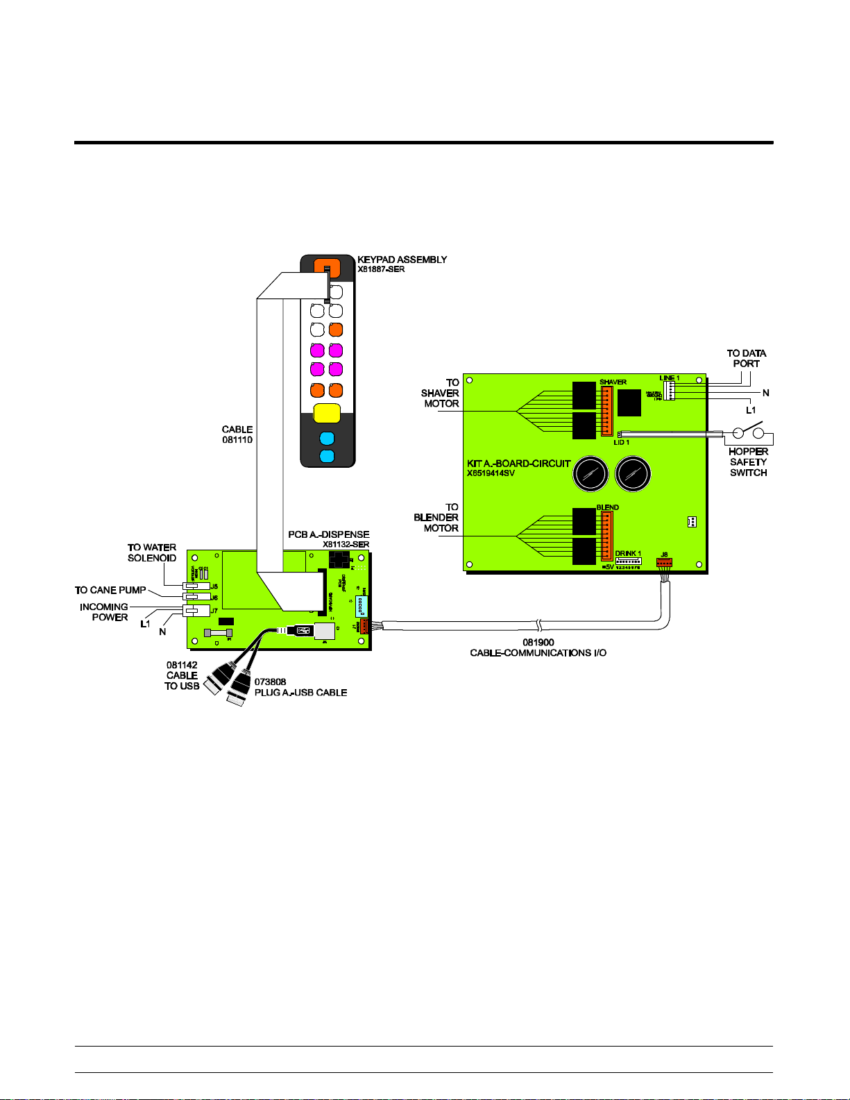
Control Overview
Controls and Systems
Figure 1
10
Model SB25
Page 15
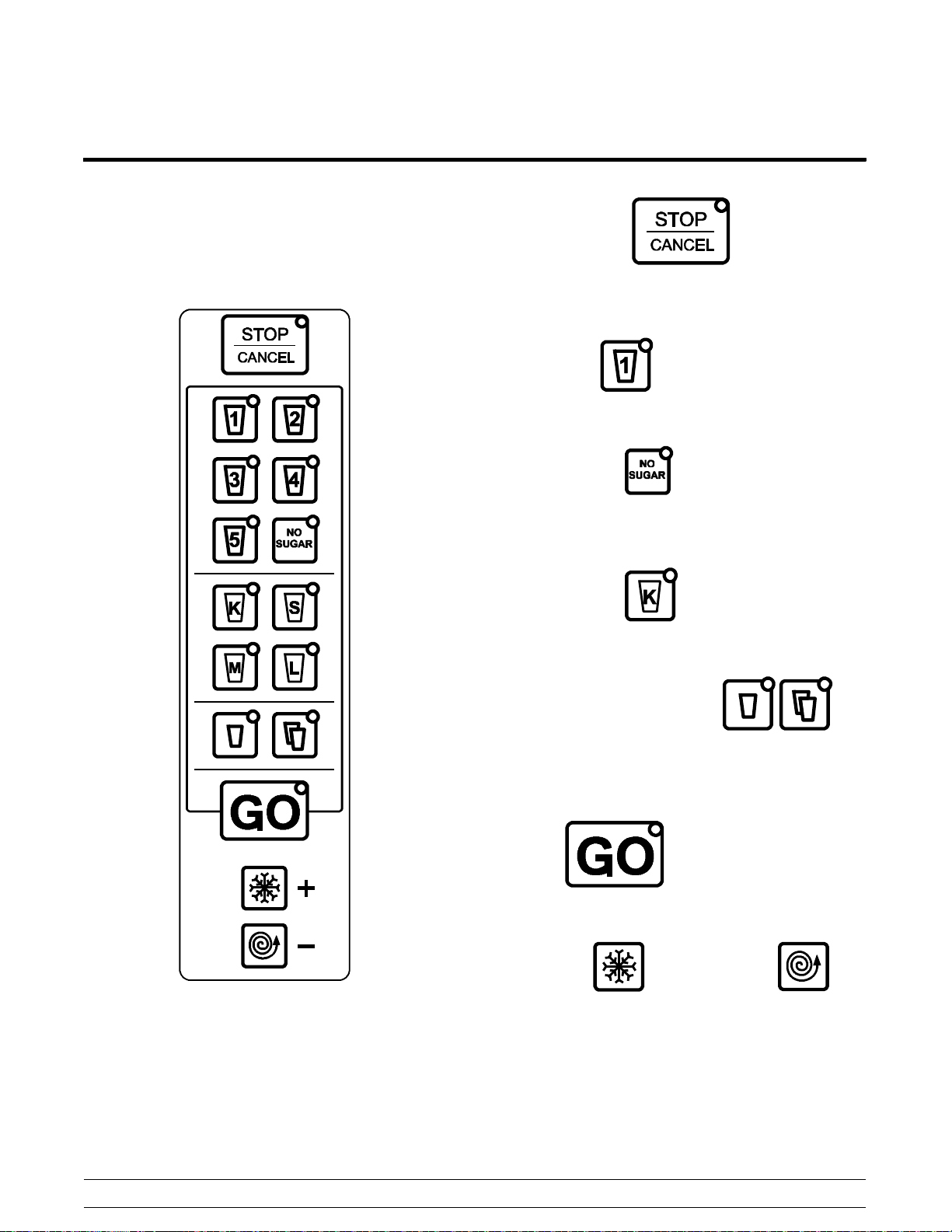
Keypad
The keypad allows the operator to control the
functions of the unit. It is located in the front face of
the blender. (See Figure 2.)
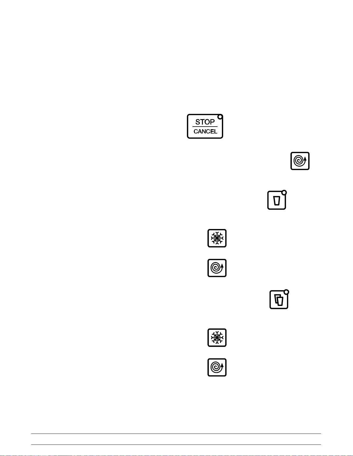
Stop/Cancel Key
Pressing this key will shut down the unit and cancel
the drink cycle.
Recipe Keys
Selects pre-programmed flavor/recipes.
NO SUGAR Key
Removes cane sugar from the drink recipe currently
being dispensed.
Figure 2
Drink Size Keys
Selects the drink size.
Single/Double Quantity Keys
Allows the operator to make a single or double
serving of K, S, and M drink sizes. It will not make a
double L drink.
GO Key
The GO key starts the selected drink cycle.
Shaver Key
These keys are used to manually shave ice and
blend product.
and Blender Key
Model SB25
11
Controls and Systems
Page 16
PC Connection
The SB25 can be connected to a PC in order to
manage recipes and system calibration, using the
supplied software. A PC running Windows XP or
greater with a USB port is required.
1. Remove the cover from the upper USB port on
the left side of the system by unscrewing the
cap counter-clockwise.
2. Connect the USB cable from the PC to the
USB-B connector on the unit.
3. Switch the main power ON.
4. The first time you connect to the unit and start
the PC software, you may be prompted to
install the proper drivers on your PC. Follow the
on screen instructions to install the proper
drivers. Note: This requires an Internet
connection.
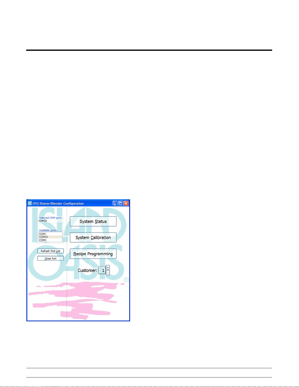
5. Open the programming software:
“OTGConfig Rels Rev A.exe”
6. Refresh the Port List and select the proper
COM Port from the list of Available Ports. This
is usually the highest numbered port in the list.
(See Figure 3.)
7. To reset the connection select “Close Port” and
reselect.
Customer Numbers
Two customer numbers can be stored in the
shaver/blender controller PCA memory, containing
separate recipe and calibration settings. These are
selected by a DIP switch setting inside the system,
located on the top edge of the dispense PCA
assembly. Position 5 is used to select the customer
number. (Position 6 is used to enable or disable the
cane pump option on the SB25, if it is functioning.)
S Customer 1 - Switch Position 5 OFF
S Customer 2 - Switch Position 5 ON
When you power up the system, the customer
selected number is displayed briefly (one second)
before showing the default menu settings.
S If recipe key 1 is on briefly at power up, the
DIP switch is set to customer 1.
S If recipe key 2 is on briefly at power up, the
DIP switch is set to customer 2.
Figure 3
Customer configurations are generated in the
supplied PC software. The main page of the
supplied software will indicate the current DIP switch
setting. Any combination of customer configurations
can be loaded into the system. If you select a
configuration that hasn't been downloaded, the
default values in the software will be used.
Controls and Systems
12
Model SB25
Page 17

Calibration
______________________________
The SB25 unit can be calibrated using the supplied
PC software or by using the manual calibration
method through the main keypad.
Target Calibration Settings
S Shaved Ice: 10 oz. (by weight)
S Water Dispense: 4 oz (by volume)
S Cane Dispense: 4 oz (by volume)
PC Calibration
Step 1
Refer to PC Connection on page 12.
Step 2
Select “System Calibration” from the supplied
software. (See Figure 4.)
Step 3
The current system Calibration Factor values for
Shave, Blend, Water and Cane dispense times are
displayed.
Step 6
Select “Reset Calibration Factors” to return all
values to 1.0.
Step 7
Select “Main Menu”, select recipe settings, and
select save to unit.
Step 4
Use the +/- buttons next to each Calibration Factor
to increase or decrease calibration settings to
achieve desired results. Note that this changes the
Calibration Factor on the shaver/blender system
immediately.
Step 5
Select the Run Cycle button next to each Calibration
Factor to run that particular function with the
Calibration Factor applied.
Figure 4
Model SB25
13
Controls and Systems
Page 18
Keypad Calibration
Test Mode
______________________________
Step 1
Enter the keypad calibration mode by holding the
Stop button until all recipe key LED's blink.
S Press recipe 1 key to change the Shave
calibration value.
S Press recipe 3 key to change the Water
calibration value.
S Press recipe 4 key to change the Cane
calibration value (Model SB25, only).
When the value to be changed has been selected, it
will blink at a slow rate, along with the recipe1 & 2
serving size LED's.
Note: The serving size LED's blink to indicate that
the calibration value can now be changed.
Step 2
Use the +/- buttons to increase or decrease the
calibration settings to achieve the desired results.
The Test Mode within the Calibration Mode allows
all motors, valves, and pumps to be run manually.
This can be useful in diagnosing motor or dispensing
issues.
Step 1
Enter the calibration mode by holding the
button for 3 seconds.
Step 2
Press and hold the manual blend button
3 seconds.
Step 3
Press the single serving button
blender motor testing:
for shaver or
for
S Press and hold the manual shave button
Step 3
Press the STOP/CANCEL button to cancel any
unsaved changes and exit the calibration mode.
Step 4
Press the NO SUGAR button to save the current
calibration value and run a test cycle of the item
being calibrated:
S Shave – dispense 10 oz of ice with the
current calibration value applied.
S Blend – run blender for “2 seconds” with the
current calibration value applied.
S Water - dispense 4 oz of water with the
current calibration value applied.
S Cane - dispense 4 oz of cane with the
current calibration value applied.
S Press “GO” to save the changes.
to run the shaver motor.
S Press and hold the manual blend button
to run the blender motor.
Step 4
Press the double serving button
dispense testing:
for water
S Press and hold the manual shave button
to run the cane pump.
S Press and hold the manual blend button
to activate the water valve.
Step 5
Press the STOP/CANCEL button to exit the Test
Mode.
Controls and Systems
14
Model SB25
Page 19
Programming & Recipe Storage
______________________________
The customer recipe information is held in the
microprocessor memory. Recipes distributed on
USB memory sticks can be uploaded to the system
automatically. Note: When new recipes are
uploaded, any recipes currently on the system
will be overwritten.
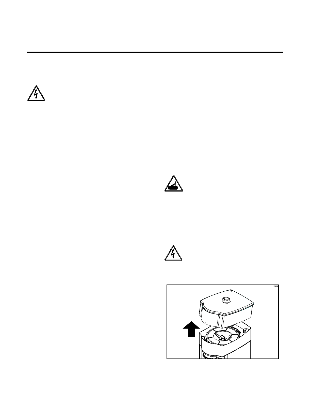
Programming Using USB Stick
Note: Do not plug in a thumb drive and the PC
USB cable at the same time.
Step 1
Switch the main power OFF.
Step 2
Remove the cover from the lower USB port on the
left side of the system by unscrewing the cap
counter-clockwise. (See Figure 5.)
Step 8
Place the main power switch in the ON position.
PC Recipe Management
The supplied software can be used to transfer drink
recipe information back and forth from a PC to the
shaver/blender. It can also be used to create USB
flash drives in order to distribute recipes to customer
sites.
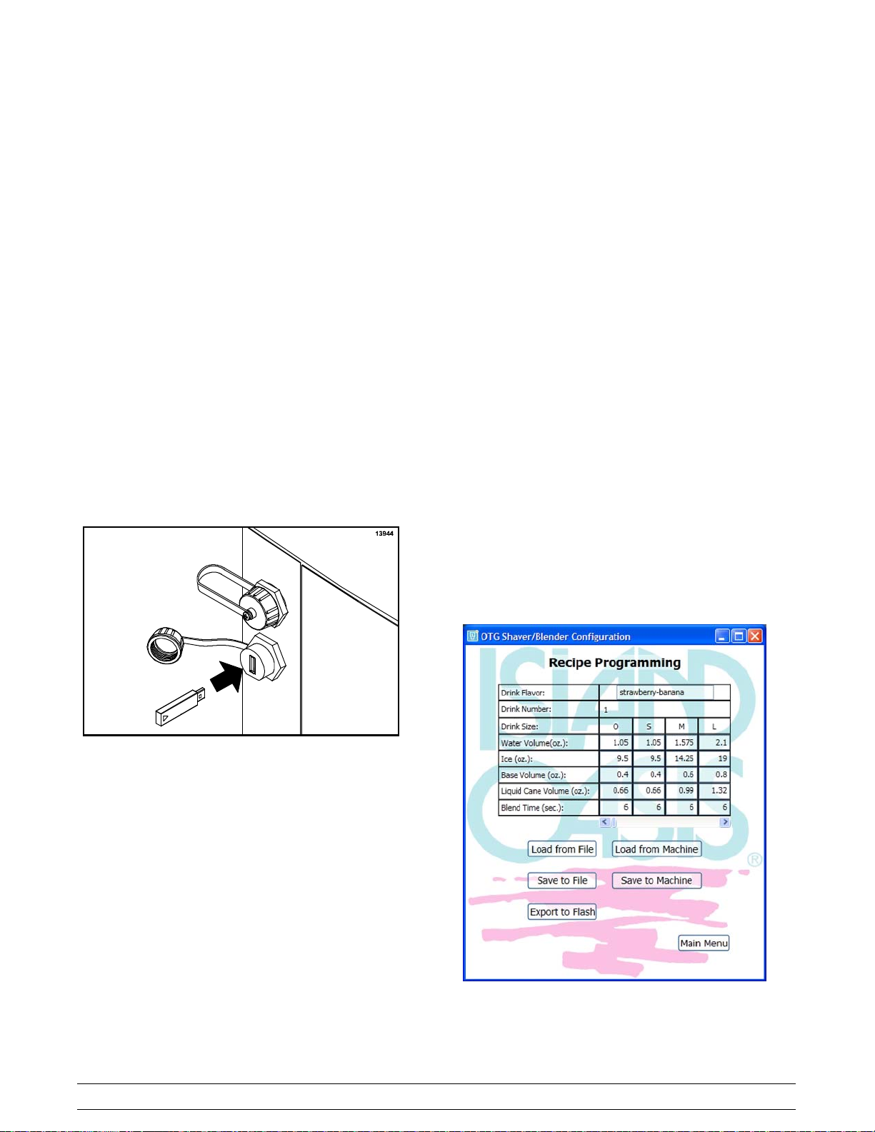
Recipe Programming
Step 1
Refer to PC Connection on page 12.
Step 2
Select “Recipe Programming” from the supplied
software. (See Figure 6.)
Figure 5
Step 3
Insert the USB stick.
Step 4
Switch the main power ON.
Step 5
The SB25 will automatically download and save the
recipeinformation to the unit.
Step 6
Place the main power switch in the OFF position.
Step 7
Remove the USB stick and reinstall the USB port
cover.
Model SB25
15
Figure 6
Controls and Systems
Page 20

Step 3
To load an existing recipe file, select “Load from
File” and browse to the folder. Select the file name
and select “Open.” This will overwrite the recipe set
shown in the table.
Step 4
To load recipes from the shaver/blender, select
“Load from Machine.” This will overwrite the recipe
set shown in the table.
Step 5
The recipe table is used to display and edit a set of
drink recipes.
a. Use the left/right arrow keys to select drink
numbers.
b. Enter the Drink Flavor - This is descriptive text to
identify the drink, e.g. “Strawberry Banana.”
c. Drink size – Corresponds to the drink sizes on
the system (Note that “O” on the PC stands for
“K” on the keypad).
d. Water Volume (oz.) – Amount of water dispensed
for each drink size.
e. Ice (oz.) – Amount of ice dispensed for each
drink size.
f. Base Volume (oz.) – Amount of flavor base that
needs to be manually added before shaving/
blending. This parameter is for reference and is
not used by the unit.
g. Liquid Cane Volume (oz.) – Amount of liquid
cane dispensed for each drink size.
h. Blend Time (sec.) – Duration of blend cycle for
each drink size.
Step 6
To store the recipe set to the PC, select “Save to
File,” browse to a folder, enter the file name, and
select “Save.”
Select “Save to Machine” to store the recipes on the
unit. This will overwrite the recipe set stored on the
system.
Step 7
TostorearecipesettoaUSBflashdrive,plugthe
drive into the PC’s USB port and select “Export to
Flash.” Select the USB device from the browser and
select “Save” (file will be named CUST1.txt,
CUST2.txt depending on the DIP switch customer
number system setting).
Step 8
Select “Main Menu” when done.
Controls and Systems
16
Model SB25
Page 21
General Repairs
IMPORTANT!
DO NOT attempt any interior repairs
until the following steps are completed. Failure
to follow these instructions may result in personal
injury or death from electrical shock or from
hazardous moving parts, as well as poor
performance or damage to the unit.
1. Disconnect the main power supply to the unit.
2. Disconnect the power cord at the plug.
3. Remove the ice hopper.
(Note: Remove the ice before removing the ice
hopper.)
4. Remove the side panels.
5. Remove the drive board cover.
6. Remove the water and cane lines.
Ice Hopper
______________________________
The ice hopper is the container for the ice cubes that
are consumed in the shaving process. The hopper
and lid have an integral magnetic mechanism that
triggers a safety switch which allows system
operation only when the hopper and lid are installed
correctly.
Disassembly
Step 1
Remove the hopper cover.
Step 2
Using a scoop, carefully remove the ice from the
hopper.
WARNING: The shaver blade is very
sharp. Cautionmustbeusedwhenworkinginor
near the shaver assembly. Failure to follow this
instruction may result in personal injury from blade
contact.
Step 3
Install the hopper cover and run the manual blend
cycle until all remaining ice is dispensed.
Step 4
Wait 30 seconds after disconnecting power
before removing the drive board cover.
Electrostatic Discharge Protection
Electrostatic Discharge (ESD) is the rapid discharge
of static electricity from one conductor to another of
a different potential.
An electrostatic discharge can damage integrated
circuits found in computer and communications
equipment. Follow instructions where noted.
Model SB25
Turn off the power switch and unplug the
power cord.
Step 5
Remove the hopper and hopper cover.
Figure 7
17
Controls and Systems
Page 22
Drive Board
______________________________
The Drive Board functions as the control center of
the Shaver/Blender. The removal of the Drive Board
is sometimes necessary to access other areas of the
system.
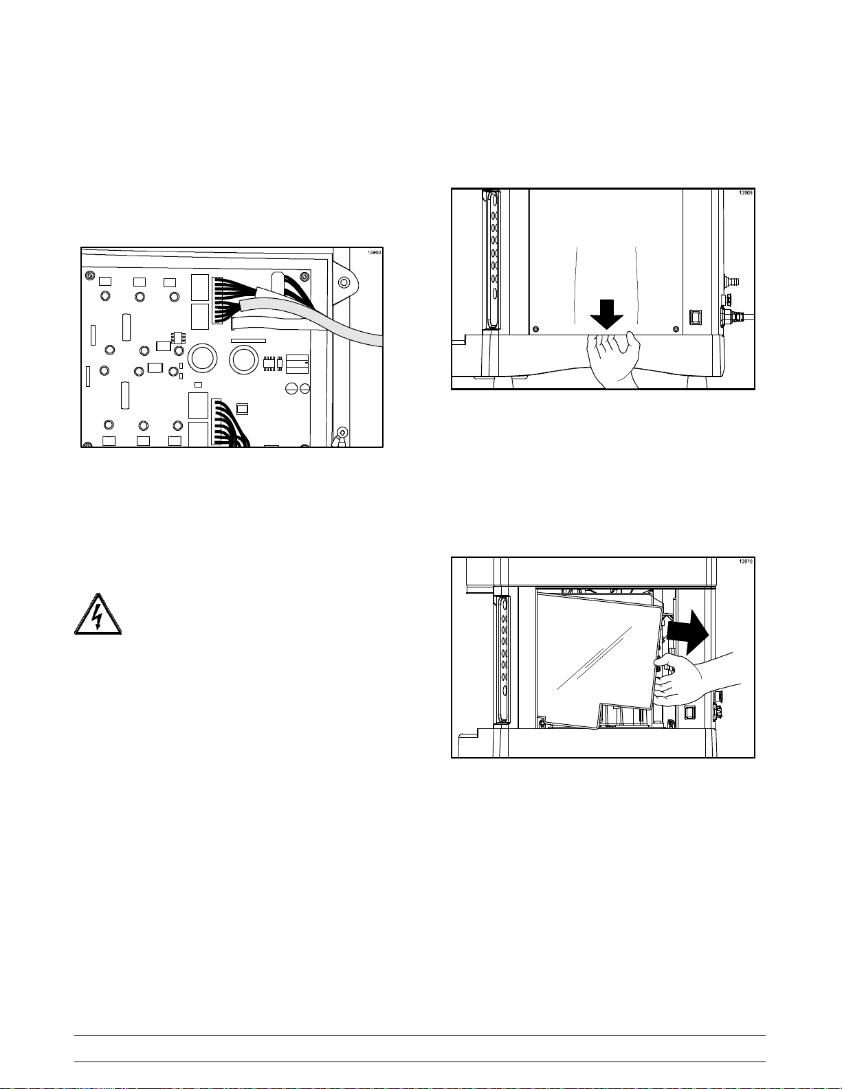
Step 5
Insert your fingers under the bottom edge of panel
and pull downward.
Figure 9
Figure 8
Note: See page 43 for the Drive Board
Troubleshooting Guide.
Disassembly
Step 1
Turn off the power switch and unplug the
power cord.
Step 2
Remove the right side panel screws.
Step 3
Remove the right side panel.
Step 4
Insert a flat screwdriver in the screw hole and bow
the cover slightly.
Step 6
Remove the screw (black box to post).
Step 7
Remove the black box cover.
Figure 10
Controls and Systems
18
Model SB25
Page 23

Step 8
Place an anti-static wrist strap around your wrist.
Attach the clip on the other end of the strap to the
ground post.
Main Drain Assembly
______________________________
The Main Drain Assembly consists of the main drain
housing, shaver assembly, shaver motor, and lid
sensor. Removal of the Main Drain Assembly is
sometimes necessary to access other areas of the
system.
Disassembly
Step 1
Turn off the power switch and unplug the
power cord.
Figure 11
Step 9
Remove the connectors.
Figure 12
Step 10
Lift the black box and pivot it around the left front
post.
Step 11
Remove the black box.
Step 2
Remove ice hopper and lid. (See page 17.)
Step 3
Remove the Drive Board. (See page 18.)
Step 4
Remove the four nuts securing the top frame.
Note: Per torque specifications, nuts are tightened
to 75 inch/pounds.
Figure 13
Model SB25
19
Controls and Systems
Page 24

Step 5
Loosen the main drain assembly. Remove the fluid
fittings from the water valve and cane pump by
pushing the gray collar toward the fitting and pulling
on the tube. Remove the main drain assembly.
Figure 14
Dispense PCB
______________________________
The Dispense PCB is the main communications link
between the Keypad, Water Dispense Unit, Cane
Dispense Unit and the Drive Board. It stores all
recipes and enables USB communications through a
PC or USB stick.
Check the fuse. Visually, the fuse filament should be
continuous and not burnt. Check the continuity with
the multimeter. The fuse should not read “OL” when
measuring ohms.
Note: Dip switch #6 must be in the ON position for
units equipped with a cane pump.
Disassembly
Step 1
Turn off the power switch and unplug the
power cord.
Step 2
Remove the left side panel.
Step 3
Remove the box cover.
Step 4
Place an anti-static wrist strap around your wrist.
Attach the clip on the other end of the strap to the
ground post.
Step 5
Remove the connectors.
Step 6
Remove the PCB mounting screws and remove the
board.
Keypad
______________________________
The keypad serves as the main control center for all
functions of the unit.
Troubleshooting
If keypad functions do not work properly, check the
connections to the keypad and the Dispense PCB
and for any condensation build-up on wire
connections. Before replacing the keypad, plug in a
new keypad and test the functions.
Figure 15
Controls and Systems
Replacement
Step 1
Turn off the power switch and unplug the
power cord.
Step 2
Remove the ice hopper and lid. (See page 17.)
Step 3
Remove the Drive Board. (See page 18.)
Step 4
Remove the main drain assembly. (See page 19.)
20
Model SB25
Page 25

Step 5
Remove the four screws securing the keypad to the
front panel.
Rotary Wing
______________________________
The rotary wing agitates the ice and forces it against
the shaver blade.
Troubleshooting
If the unit does not shave ice, but the motor is
running check for the following:
S Blade damage
S Possible broken or cored-out rotary wing
Disassembly
Step 1
Remove the ice hopper and lid. (See page 17.)
Step 2
Figure 16
Step 6
Disconnect the ribbon cable from the keypad. The
ribbon cable header is equipped with a locking
mechanism. To disconnect the ribbon cable, move
the two locking tabs away from the header, toward
the outside of the board.
Turn off the power switch and unplug the
power cord.
WARNING: The shaver blade is very
sharp. Cautionmustbeusedwhenworkinginor
near the shaver assembly. Failure to follow this
instruction may result in personal injury from blade
contact.
Step 3
Remove the ice shaver cone cover by pressing the
rear tab inward and rotating the cover clockwise.
Model SB25
Figure 17
21
Figure 18
Controls and Systems
Page 26

Step 4
Remove the ice scrambler by squeezing the tabs
inward and rotating clockwise while holding the wing
securely. (Note: Secure the o-ring for re-assembly.)
Figure 19
Step 5
Remove the rotary wing by lifting it straight up off the
motor shaft.
Shaver Motor
______________________________
Description
Disassembly
Step 1
Remove the ice hopper and lid. (See page 17.)
Step 2
Turn off the power switch and unplug the
power cord.
Step 3
Remove both side panels.
Step 4
Remove the drive board. (See page 18.)
Step 5
Remove the shaver motor ground wire from the
grounding post.
Step 6
Remove the rotary wing. (See page 21).
Step 7
Remove the main drain assembly and place it on a
flat surface. (See page 19.)
The shaver motor is the power supply for the ice
shaving function.
Troubleshooting
If the shaver motor is not running, check the
following:
1. Power supply
2. Cycle unit OFF, then ON
3. Safety switch (hopper/cover)
4. Ice jam in hopper
5. Possible broken/cored out wing
6. Shaver motor for damage
7. Keypad error
8. Main power board
Note: See page 42 for Shaver Motor
Troubleshooting Guide.
Step 8
Remove the 4 bolts securing the shaver motor.
Note: Per torque specifications, the bolts tightened
to 76 inch/pounds.
Figure 20
Controls and Systems
22
Model SB25
Page 27

Blender Motor
______________________________
Description
Disassembly
Step 1
Turn off the power switch and unplug the
power cord.
Step 2
Remove ice hopper and lid. (See page 17.)
The blender motor is the power supply for the
blender function.
Troubleshooting
If unit does not blend, check the following:
1. Power supply
2. ON-OFF/Reset button
3. Safety switch (hopper/cover)
4. Combination of drink sizes
5. Portion of product used for drink size
6. Blender pitcher for damage
Step 3
Remove the Drive Board. (See page 18.)
Figure 21
Step 4
Position the unit on its side as shown in Figure 22.
7. Blender motor
8. Main power board
Note: See page 42 for Blender Motor
Troubleshooting Guide.
Model SB25
23
Figure 22
Controls and Systems
Page 28

Step 5
Remove the blender motor screws and remove the
motor. (Note: Per torque specifications, the screws
are tightened to 16 inch/pounds.)
To Remove: Holding the splash guard at a slight
angle, lift up and pull out and away from the ice
chute to disengage the hooks from the ice chute.
Figure 25
Figure 23
Step 6
Remove the wire harness by pulling it through the
access hole. Bending the wire harness against the
connector is necessary in order to pull the harness
out. Do not cut the wires.
Ice Chute & Splash Guard
______________________________
Splash Guard
To Install: Hold the splash guard at a slight angle
and lift the splash guard up and forward, locking the
hooks of the splash guard onto the posts on the ice
chute.
Ice Chute
To Remove: Squeeze the tabs on the ice chute and
gently pull down on the chute to disengage.
Figure 26
To Install: Lifttheicechuteupintoplaceinthe
main drain. Be sure both tabs are locked securely
into place by gently pulling down on the ice chute.
Figure 24
Controls and Systems
24
Figure 27
Model SB25
Page 29

Shaver Cartridge
______________________________
The shaver blade has a single edge design that
cannot be re-sharpened.
Troubleshooting
If the shaved ice becomes inconsistent in the
texture, check the blade for damage and dullness.
Replace the blade if necessary.
If there is not enough ice being shaved, check the
blade for dullness. The timing can also be adjusted
for the required ice flow.
Replacement
Step 1
Turn off the power switch and unplug the
power cord.
Step 2
Remove the ice hopper and lid. (See page 17.)
Step 4
Remove ice scrambler by squeezing the tabs inward
and rotating clockwise while holding the wing
securely. (Note: Secure the o-ring for re-assembly.)
Figure 29
Step 5
Slide the shaver cartridge out of the cone.
WARNING: The shaver blade is very
sharp. Cautionmustbeusedwhenworkinginor
near the shaver assembly. Failure to follow this
instruction may result in personal injury from blade
contact.
Step 3
Remove the ice shaver cone cover by pressing the
rear tab inward and rotating the cover clockwise.
Figure 28
Figure 30
Step 6
Reassemble the system and check the ice volume
for proper calibration.
Model SB25
25
Controls and Systems
Page 30

On-Off/Reset Switch
______________________________
The On-Off/Reset switch provides power to the unit
and is also used to reset the Drive Board in the
event of a shaver or blender motor lock.
Troubleshooting
If there is no power to the unit check the following:
1. Check outlet
2. Check power cord at outlet
3. Toggle switch
4. Drive board and dispense board fuses
5. Check connection at the switch to the harness.
Step 4
Remount the switch into the panel.
Figure 32
Drain System
______________________________
Figure 31
Replacement
Step 1
Disconnect the power cord from the outlet.
Step 2
Press the toggle switch snap-in feature to remove
the panel (keep wires connected).
Step 3
Using a pair of needle nose pliers, remove the wire
connectors, one at a time, and reconnect to the new
switch.
The shaver/blender drain system consists of a
series of hoses. There is one interior hose and one
exterior hose that connect to an exterior drip pan.
These must be kept clean to maintain water flow.
The exterior hose must be running downhill, with no
kinks.
Note: This is not required when the shaver unit is
being used with the rinse station. When using the
rinse station, the drain pan should be removed.
Troubleshooting
If the drain lines are not kept clean, a build-up of
algae will occur. This will block the water flow and
cause back-up and possible leaks. The use of a
cleaner will prevent this problem. To clean clogged
drain lines, use a small wire bottle brush available
from your Taylor Distributor. To check for leaks,
pour water into the top and bottom drain holes.
Note: To remove the drain hose from its
connection, if necessary, cut the hose with a razor
blade. This will allow for easy removal.
Controls and Systems
26
Model SB25
Page 31

Blender Pitcher
______________________________
Water Dispense
______________________________
The blender pitcher was designed with no
replaceable wear items and will only sit on the
blender base in one position. (Note: Never wash the
blender pitcher in the dishwasher.)
Safety Switch
______________________________
The purpose of the safety switch is to interrupt
power to the unit when the cover is removed. If the
safety switch is not performing this function, check
that the white safety switch rod located in the rear
left hand corner of the ice hopper is in place.
Check to see if the magnet located in the rear left
hand corner of the hopper cover which engages the
safety switch rod is in place. Replace the ice hopper
or the ice hopper cover if either component is
missing.
Correct Cover Placement
The water dispense supplies water to the blender
pitcher during drink dispensing.
Troubleshooting
If water is not dispensed or an incorrect amount is
dispensed, check the following:
Step 1
Make sure the water line is connected to the rear of
the system and is free from kinks.
Step 2
Make sure that adequate water pressure is being
supplied to the system.
Step 3
Make sure the water filtration is working properly.
Figure 33
Incorrect Cover Placement
Figure 34
Step 4
Check the system for leaks.
Disassembly
Step 1
Turn off the power switch and unplug the
power cord.
Step 2
Remove the ice hopper and lid. (See page 17.)
Step 3
Remove the main drain assembly. (See page 19).
Step 4
Remove the Dispense PCB cover.
Model SB25
27
Controls and Systems
Page 32

Step 5
Disconnect and remove the water valve connector
from the Dispense PCB.
Step 6
Remove the water inlet tube from the manifold
assembly.
Step 7
Remove the manifold mounting screws located in
the Dispense PCB mounting box.
Figure 35
Step 8
Removethe manifold.
Cane Dispense
______________________________
The Cane Dispense supplies liquid cane to the
blender pitcher during drink dispensing.
Troubleshooting
If cane is not dispensed or an incorrect amount is
dispensed, check the following:
Step 1
Make sure the cane source is present and has an
adequate supply.
Step 2
Make sure the cane line is connected to the rear of
the system and is free from kinks.
Step 3
Check the system for leaks.
Disassembly
Step 1
Turn off the power switch and unplug the
power cord.
Step 2
Remove the ice hopper and lid. (See page 17.)
Step 3
Remove the Drive Board. (See page 18.)
Step 4
Remove the main drain assembly. (See page 19).
Step 5
Remove the Dispense PCB cover.
Step 6
Remove the cane pump connector from the
Dispense PCB.
Figure 36
Controls and Systems
28
Figure 37
Model SB25
Page 33

Step 7
Remove the cane pump ground lug from the
grounding post.
Step 8
Remove the four (4) screws from the rear of the unit.
Remove the pump assembly.
Figure 38
Step 9
Remove the elbow connection from the pump inlet
by sliding the retaining tab down and pulling out the
elbow.
Figure 39
Step 10
Remove the inner jam nut holding the cane inlet
connector and slide the pump inlet tube and elbow
out through the rear of the unit.
Model SB25
29
Controls and Systems
Page 34

Blender Drive Board
Figure 40
Note: See page 43 for blender drive board LED indicator troubleshooting.
ITEM DESCRIPTION
1 KIT A.-MOTOR SHAVER
*2 DRAIN-MAIN W/SAFETY SWITCH
**3 POWER SUPPLY 115 VAC
4 FUSE-BOARD-DRIVER I.O.
5 LED-HEARTBEAT
6 LED-TROUBLESHOOTING
**7 COMMUNICATION CABLE TO DISPENSE BOARD
8 KIT A.-MOTOR BLENDER
* LID-IN-PLACESENSOR IS IN ICE HOPPER SUPPORT
** PART OF 066891 HARNESS
Controls and Systems
30
Model SB25
Page 35

Blender Pitcher Rinse Station
The blender pitcher rinse station is activated when a
pitcher is properly placed in position, which lowers
the actuator. When the actuator is lowered, the
magnet inside the actuator closes a reed switch
beneath the bowl. After a short delay, rinse water
begins to flow from the spray rinse nozzle.
If the water pressure to the unit is correct, the water
will flow for approximately six seconds and dispense
approximately 25 ounces of water.
Note: The rinse duration setting is adjustable and
can be set to 5, 7, 9, or 12 seconds. (See page 32.)
To repeat this cycle, the pitcher must be removed,
allowing the actuator to rise to its natural “up”
position. This action opens the reed switch. Once
the reed switch is open, the rinse cycle resets. This
allows the cycle to repeat when another pitcher is
placed on the rinse station.
Model SB25
Figure 41
31
Controls and Systems
Page 36

Blender Pitcher Rinse Station Repairs
Rinse Duration Settings
______________________________
The rinse duration is adjustable to 5, 7, 9, or 12
seconds. Adjust the rinse time by using the rotary
dip switch on the control PCB located under the
bottom cover of the unit. Note the dip switchsettings
listed in the table below.
Figure 42
Water Usage (gallons)
Based on Inlet Pressure & Rinse Time Settings
Dip
Switch
Setting
0
1
2
3
Rinse
Times
5 seconds 0.29 gal 0.33 gal 0.41 gal
7 seconds 0.41 gal 0.47 gal 0.57 gal
9 seconds 0.52 gal 0.60 gal 0.74 gal
12 seconds 0.69 gal 0.80 gal 0.98 gal
Incoming Water Pressure
30 psi 40 psi 60 psi
parts as well as poor performance or damage to the
unit.
1.
2. Disconnect the water supply at the quick
connect fitting.
3. Remove the front pan assembly.
4. Remove the bottom cover by removing the
screws.
5. Install a jumper on P1 to put the drive board
into the Test Mode. This will allow the triggers
to be tested individually.
Turn off the main power to the unit.
Figure 43
Rinse Station Triggers
______________________________
The Rinse Station detects the placement of the
blender pitcher on the rinse station pitcher platform.
If the pitcher triggers are not working properly, an
adjustment to the reed switches may be necessary.
The main power supply(s) to the unit
must be disconnected prior to performing any
installation, maintenance, or repairs. Failure to
follow this instruction may result in personal injury or
death from electrical shock or hazardous moving
Controls and Systems
Figure 44
6. Replace the front pan.
7. Place the main power switch in the ON position.
8. Test the triggers separately.
32
Model SB25
Page 37

9. Adjust the reed switches until the triggers are
functioning properly. Functioning triggers will
cause an audible click of the solenoid.
Figure 45
10. Swap the triggers and ensure that the triggers
will function in either position.
Figure 46
11.
12. Remove the jumper.
13. Reassemble the unit.
Turn off the main power.
Filter Screen
______________________________
The filter is designed to keep debris away from the
solenoid that triggers the flow of water through the
Rinse Station spray nozzle.
To clean or replace the filter screen, perform the
following steps.
1.
2. Disconnect the power adaptor from the main
power jack.
3. Disconnect the water supply at the quick
connect fitting.
4. Remove the front pan assembly.
5. Remove the filter cover by turning the cover to
the left 1/4 turn.
Turn off the main power to the unit.
Figure 47
6. Remove the hex cap on the filter.
Figure 48
7. Remove and clean or replace the screen.
8. Reassemble the unit.
Model SB25
33
Controls and Systems
Page 38

Main Power Wiring Harness
______________________________
The main power wiring harness provides power to
the main control PCB.
To replace the main wiring harness, perform the
following steps.
5. Disconnect the wiring harness from the PC
board.
1.
2. Disconnect the power adaptor from the main
power jack.
3. Remove the bottom cover.
4. Remove the power cover by removing the
screw.
Turn off the main power to the unit.
Figure 50
6. Remove the main power jack from the Rinse
Station base.
Figure 51
7. Remove the main power switch and pull the
wiring harness out through the main power
switch hole.
Figure 49
Controls and Systems
8. Reverse the process to replace the wiring
harness.
34
Model SB25
Page 39

Rinse PCB
______________________________
Rinse Manifold Replacement
______________________________
The rinse PCB functions as the control center of the
Rinse Station.
To replace the rinse PCB, perform the following
steps.
1.
2. Disconnect the power adaptor from the main
power jack.
3. Disconnect the water supply at the quick
connect fitting.
4. Remove the bottom cover.
5. Disconnect all four (4) connections from the
rinse PC board.
Turn off the main power to the unit.
To replace the rinse manifold, perform the following
steps.
1.
2. Disconnect the power adaptor from the main
power jack.
3. Disconnect the water supply at the quick
connect fitting.
4. Remove the bottom cover.
5. Disconnect the tubing from each end of the
water valve manifold.
Turn off the main power to the unit.
Figure 52
6. Remove the four (4) screws holding the PC
board onto the base.
7. Install the new PC board.
8. Reassemble the unit.
Figure 53
6. Remove the three (3) screws which secure the
water valve manifold to the rinse station
bracket.
7. Remove the three (3) screws which secure the
bracket to the base.
8. Install the new water valve manifold.
9. Reconnect the tubing.
10. Reinstall the bottom cover.
Model SB25
35
Controls and Systems
Page 40

Notes:
Controls and Systems
36
Model SB25
Page 41

Section 3: Troubleshooting
S General Troubleshooting
S Rinse Station Troubleshooting
S Blender Troubleshooting
Model SB25
37
Troubleshooting
Page 42

General Troubleshooting
PROBLEM POSSIBLE CAUSE REMEDY
Blender pitcher is damaged. Abuse or excessive wear. Replace blender pitcher.
Shaved ice has inconsistent texture. The shaver blade is worn. Replace the shaver blade.
Unit runs, but does not shave ice. The ice hopper is empty. Refill the hopper.
The shaver blade is damaged. Replace the shaver blade.
Unit runs, but does not blend ice. Wrong volume or product was
added.
Wrong volume of ice. Check the ice volume. Adjust
Wrong volume of water. Check the water volume. Adjust
Wrong volume of cane sugar. Check the cane sugar volume.
Unit has no power and no lights. The power switch is OFF Place the power switch in the ON
The power cord is not plugged in. Check the connection at the
Safety switch is open. Ensure that the hopper cover is
Drive board and/or dispense
board issue and/or fuse blown.
Water is not dispensing. Water line at the back of the unit
is not connected.
Water line is kinked. Straighten water line.
Low water pressure in the store. Check filter and store plumbing.
Remeasure and pour product.
calibration as needed.
calibration as needed.
Adjust calibration as needed.
position.
outlet and ensure the outlet is
functioning.
properly seated on the hopper.
Check motors, replace board /
fuse.
Connect the water line.
Water is leaking from the unit. Poor fitting/hose connection. Check all visible fittings and
ensure all hoses are fitted into
the fittings properly.
Cracked hose. Replace cracked hose.
Broken fitting. Replace fitting.
Troubleshooting
38
Model SB25
Page 43

PROBLEM POSSIBLE CAUSE REMEDY
Cane sugar is leaking from the unit. Poor fitting/hose connection. Check all visible fittings and
ensure all hoses are fitted into
the fittings properly.
Cracked hose. Replace hose.
Broken fitting. Replace fitting.
Pump issue. Check pump and replace if
necessary.
Cane sugar is not dispensing or is
dispensing an incorrect amount.
STOP/CANCEL button and recipe
buttons are flashing.
Recipe key #1 - fast blink (hopper/lid
sensor fault).
Recipe key #2 - fast blink (shaver is
jammed).
The cane sugar bottle is missing
or has an inadequate supply.
Poor fitting/hose connection. Check the connection at the rear
Cracked hose. Repair/replace hose.
Broken fitting. Replace the fitting.
The pump is not working. Evaluate the pump. Replace if
Cable is disconnected or has a
poor connection.
Hopper cover is not seated
properly.
Hopper is not seated properly. Adjust hopper to sit properly in
Safety switch issue. Check ribbon cable connection
Large piece of ice has jammed
the shaver.
Replace the cane sugar supply.
of the unit.
necessary.
Properly connect the cable.
Adjust hopper cover. Replace
cover if broken.
main unit. Replace hopper if
broken.
on main board/replace safety
switch board if necessary .
Remove ice, fill with new ice
cubes, and reset the unit.
Recipe key #2 - slow blink (shaver is
over temperature).
Model SB25
Foreign object is causing the
jam.
Motor failure. Reset the unit. Use the Motor
The shaver motor is over
temperature.
Motor failure. Use the Motor Troubleshooting
39
Remove the object and reset the
unit.
Troubleshooting Guide to
evaluate the motor and replace if
necessary.
Reset the unit. Use the Motor
Troubleshooting Guide to
evaluate the motor and replace if
necessary.
Guide to evaluate the motor and
replace if necessary.
Troubleshooting
Page 44

PROBLEM POSSIBLE CAUSE REMEDY
Recipe key #2 - continuous
illumination (thermistor open fault).
Recipe key #3 - fast blink (blender
over temperature or jam).
Recipe key #3 - slow blink (blender
over temperature)
Recipe key #3 - continuous
illumination (thermistor open fault).
Recipe key #4 - fast blink (over
temperature fault).
Recipe key #4 - slow blink (low bus
voltage).
Motor failure. Use the Motor Troubleshooting
Guide to evaluate the motor and
replace if necessary.
Blender motor is jammed. Reset the unit and press the
BLEND key. Repeated jams
indicate a failed blender motor.
Use the Motor Troubleshooting
Guide to evaluate the motor and
replace if necessary.
The blender motor is over
temperature.
Motor failure. Use the Motor Troubleshooting
Motor drive board is over
temperature.
Low voltage supplied to unit. Use the Drive Board
Reset the unit. Use the Motor
Troubleshooting Guide to
evaluate the motor and replace if
necessary.
Guide to evaluate the motor and
replace if necessary.
Reset the unit. Use the Drive
Board Troubleshooting guide to
evaluate the board and replace if
necessary.
Troubleshooting guide to
evaluate the board and replace if
necessary.
Recipe key #1, 2, 3, or 4 - fast blink
(communication fault).
No communication between the
keypad and the dispense board.
Check the ribbon cable
connections. Replace keypad,
ribbon cable, or the dispense
PCB if necessary.
Troubleshooting
40
Model SB25
Page 45

Rinse Station Troubleshooting
PROBLEM POSSIBLE CAUSE REMEDY
Unit will not rinse. The power switch is in the OFF
position.
The power plug is not inserted
into the power jack.
The DC converter is not plugged
into the wall outlet.
The DC converter is not
providing 24 volts.
The reed switch(es) is not in
position or is defective.
One or both actuators are
missing or missing a magnet.
The rinse PCB is defective. Evaluate PCB and replace if
Blender pitcher is not being rinsed
completely.
The water line at the back of the
unit is not connected.
The water line is kinked. Straighten the water line.
Cold water is being used for
rinsing.
The rinse cycle is not long
enough.
Place the power switch in the ON
position.
Check/correct the connection at
the rear of the unit.
Check/correct the connection at
the outlet.
Check the output of the
converter.
Check position of reed switch. It
should be fully inserted into the
threads. Replace if necessary.
Replace, if necessary.
necessary.
Connect the water line.
Use warm water to aid in the
rinsing process.
Adjust the cycle time on the Rinse
PCB.
Blender pitcher is not being rinsed
completely.
Water is leaking from the unit. Poor fitting/hose connection. Check all visible fittings and
Unit is not draining. The drain line is kinked. Straighten the drain line.
Low water pressure in the store. Inform the store.
ensure all hoses are fitted into
the fittings properly.
The hose is cracked. Replace the hose if necessary.
Broken fitting. Replace the fitting if necessary.
The water manifold is defective. Repair with service parts; replace
if necessary.
There is no air gap between the
drain line and the drain.
The drain line is clogged. Unclog the drain line.
Provide air gap.
Model SB25
41
Troubleshooting
Page 46

Blender Troubleshooting
Ice Shaver Motor Troubleshooting
1. Pin Continuity
a. Pins 8, 9, and 10 should have continuity.
b. Pins 8, 9, and 10 should NOT have
continuity to pins 1 -7.
c. No pins should have continuity to ground.
If any of the continuity tests above fail, replace
the motor.
2. Motor Shaft
a. Facing the motor shaft, turn the shaft
counter-clockwise. Use caution as the
shaver blade is extremely sharp. The shaft
should turn smoothly, not drag or make a
noise while turning. (Note: This motor
requires some force to turn and will cog or
step into position.) If the motor does not
turn freely, replace the motor.
3. Power Leads Resistance
a. Remove the orange connector from the
drive board and insert the header into the
connector.
Blender Motor Troubleshooting
1. Pin Continuity
a. Pins 1, 2, and 3 should have continuity.
b. Pins 1, 2, and 3 should NOT have
continuity to pins 4 - 10.
c. No pins should have continuity to ground.
If any of the continuity tests above fail, replace
the motor.
2. Motor Shaft
a. Facing the motor shaft, turn the shaft
(using a metal object) counter-clockwise.
The shaft should turn smoothly, not drag
or make a noise while turning. (Note: This
motor turns freely with minimal force and
does not cog.)
3. Power Leads Resistance
a. Remove the orange connector from the
drive board and insert the header into the
connector.
b. Check the resistance between the motor
power leads (red, white, and black). This
reading should be ~ 11.3 Ω.The
acceptable range is 9.8 Ω to 12.3 Ω.Ifthe
resistance is outside the acceptable range,
replace the motor.
c. Check resistance between the two gray
wires (thermistor). The reading should be
~ 11.3 KΩ at 70 F. The typical range at 70
Fis8.8KΩ to 13.65 KΩ. If the multimeter
reads “OL”, the thermistor is broken. If the
multimeter displays less than 5 Ω or “0”,
the thermistor is shorted. If the thermistor
is broken or shorted, replace the motor.
d. Check continuity between the ground
(green/yellow) wire and each lead, one at
a time. The multimeter should display “OL”
for each measurement. If not, there is a
dead short in the motor and the motor
should be replaced.
b. Check resistance between the motor
power leads (red, white, and black). This
reading should be ~ 1.3 Ω. The acceptable
range is 0.8 Ω to 1.5 Ω. If the resistance is
outside the acceptable range, replace the
motor.
c. Check resistance between the two gray
wires (thermistor). The reading should be
~ 11.3 KΩ at 70 F. The typical range at 70
Fis8.8KΩ to 13.65 KΩ. If the multimeter
reads “OL”, the thermistor is broken. If the
multimeter displays less than 5 Ω or “0”,
the thermistor is shorted. If the thermistor
is broken or shorted, replace the motor.
d. Check continuity between the ground
(green/yellow) wire and each lead, one at
a time. The multimeter should display “OL”
for each measurement. If not, there is a
dead short in the motor and the motor
should be replaced.
Troubleshooting
42
Model SB25
Page 47

Drive Board Troubleshooting
1. Check the supply circuit providing power to the
machine for proper voltage (~120 VAC).
2. Turn the machine off, unplug, and wait 10
seconds for the charged capacitors to lose
charge. Expose the drive board and check
these items in the following order:
a. Make sure all connectors are seated firmly
onto their pins. Loose or unseated
connectors will cause fault readings.
b. Check the fuse. Visually, the fuse filament
should be continuous and not burnt. Check
continuity with the multimeter. The fuse
should not read “OL” when measuring
ohms.
c. Plug in and turn on the machine. Locate
the green LED (D36) on the drive board,
which is approximately 1.5” above the
lower right corner of the drive board. The
green LED should be illuminated
continuously. If the LED is not illuminated,
the board is defective. Replace the drive
board.
d. Locate the red LED (D21) on the drive
board, which is approximately 0.5” above
the lower right corner of the drive board.
4. If the LED is flashing 2 times, pauses
and repeats, the drive board detects a
locked blender motor. Check for
obstructions in the blender pitcher.
Troubleshoot the blender motor.
5. If the LED is flashing 3 times, pauses
and repeats, the drive board detects a
locked ice shaver motor. Check for
obstructions in the ice hopper.
Troubleshoot the ice shaver motor.
6. If the LED is flashing 4 times, pauses
and repeats, the drive board detects
over temperature of the blender motor.
This may occur due to high frequency
use of the machine. If the blender
motor connector is not seated, this
error may occur. Troubleshoot the
blender motor.
7. If the LED is flashing 5 times, pauses
and repeats, the drive board detects
over temperature of the ice shaver
motor. This may occur due to high
frequency use of the machine. If the
ice shaver motor connector is not
seated, this error may occur.
Troubleshoot the ice shaver motor.
1. If the LED is flashing 1 second on then
1 second off, the drive board operation
is normal.
2. If the LED is flashing 2 pulses per
second, the drive detects low voltage
on the power bus. If the supply circuit
voltage is correct, replace the drive
board.
3. If the LED is flashing once every two
seconds, the ice hopper lid switch is in
the open state. Check that the ice
hopper lid is on and the sensor pulls up
magnetically. Check that the LID1
connector is firmly attached to the
board. Simulate a closed state on the
drive board by jumping LID1 pins
together with a two pin jumper or a
patch cord. If the error goes away
while jumped, check the lid sensor
mechanism. If jumping LID1 does not
change the state of the error, replace
the drive board.
8. If the LED is flashing 6 times, pauses
and repeats, the drive board detects
over temperature of the motor. This
may occur due to high frequency use
of machine. The drive board heat sink
is a black section of metal below the
left side of the electronics. If the metal
is cool while the control indicates over
temperature, replace the drive board. If
the metal is hot, troubleshoot both
motors.
9. If the LED is flashing 8 times, the
blender circuit detects an over current
fault. Field test the motor. If the motor
is okay and the fault persists, replace
the drive.
10. If the LED is flashing 9 times, the
shaver circuit detects an over current
fault. Field test the motor. If the motor
is okay and the fault persists, replace
the drive.
Model SB25
43
Troubleshooting
Page 48

11. If the LED is flashing 10 times, the
blender motor winding has a short to
motor case. Field test the motor.
**(Controller will not be damaged by
bad motor.) **This reports on
Touchscreen as BLENDER MOTOR
LOCK. Check software version. This
applies to v2.98 USA; 1.30 and later
for International.
12. If the LED is flashing 11 times, the
shaver motor winding has a short to
motor case. Field test the motor.
**(Controller will not be damaged by
bad motor.) **This reports on
Touchscreen as SHAVER MOTOR
LOCK. Check the software version.
This applies to v2.98 USA; 1.30 and
later for International.
Troubleshooting
44
Model SB25
Page 49

Section 4: Parts
S Warranty Explanation
S Exploded Views
S Parts List
S Wiring Diagram
Model SB25
45
Parts
Page 50

Warranty Explanation
TAYLOR COMPANY LIMITED WARRANTY ON TAYLOR GENUINE PARTS
Taylor Company, a division of Carrier Commercial Refrigeration, Inc. (“Taylor”) is pleased to provide this limited
warranty on new Taylor genuine replacement components and parts available from Taylor to the market generally
(the “Parts”) to the original purchaser only.
LIMITED WARRANTY
Taylor warrants the Parts against failure due to defect in materials or workmanship under normal use and service
as follows. All warranty periods begin on the date of original installation of the Part in the Taylor unit. If a Part fails
due to defect during the applicable warranty period, Taylor, through an authorized Taylor distributor or service
agency, will provide a new or re-manufactured Part, at Taylor’s option, to replace the failed defective Part at no
charge for the Part. Except as otherwise stated herein, these are Taylor’s exclusive obligations under this limited
warranty for a Part failure. This limited warranty is subject to all provisions, conditions, limitations and exclusions
listed below and on the reverse (if any) of this document.
Part's Warranty Class Code or Part
Class 103 Parts¹ Three (3) months
Class 212 Parts² Twelve (12) months
Class 512 Parts Twelve (12) months
Class 000 Parts No warranty
Taylor Part #072454 (Motor-24VDC *C832/C842*) Four (4) years
LIMITED WARRANTY CONDITIONS
1. If the date of original installation of the Part cannot be otherwise verified, proof of purchase may be required
at time of service.
2. This limited warranty is valid only if the Part is installed and all required service work in connection with the
Part is performed by an authorized Taylor distributor or service agency.
3. The limited warranty applies only to Parts remaining in use by their original owner at their original installation
location in the unit of original installation.
4. Installation, use, care, and maintenance must be normal and in accordance with all instructions contained in
the Taylor Operator’s Manual.
5. Defective Parts must be returned to the authorized Taylor distributor or service agency for credit.
6. This warranty is not intended to shorten the length of any warranty coverage provided pursuant to a separate
Taylor Limited Warranty on freezer or grill equipment.
Limited Warranty Period
7. The use of any refrigerant other than that specified for the unit in which the Part is installed will void this
limited warranty.
1, 2
Except that Taylor Part #032129SER2 (Compressor-Air-230V SERV) and Taylor Part #075506SER1
(Compressor-Air-115V 60HZ) shall have a limited warranty period of twelve (12) months when used in Taylor
freezer equipment and a limited warranty period of two (2) years when used in Taylor grill equipment.
Parts
46
Model SB25
Page 51

LIMITED WARRANTY EXCEPTIONS
This limited warranty does not
1. Labor or other costs incurred for diagnosing, repairing, removing, installing, shipping, servicing or handling of
defective Parts, replacement Parts, or new Parts.
2. Normal maintenance, cleaning and lubrication as outlined in the Taylor Operator’s Manual, including cleaning
of condensers or carbon and grease buildup.
3. Required service, whether cleaning or general repairs, to return the cooking surface assemblies, including
the upper platen and lower plate, to an operational condition to achieve proper cooking or allow proper
assembly of release sheets and clips as a result of grease build-up on the cooking surfaces, including but
not limited to the platen and plate, sides of the shroud or top of the shroud.
4. Replacement of cooking surfaces, including the upper platen and lower plate, due to pitting or corrosion (or
in the case of the upper platen, due to loss of plating) as a result of damage due to the impact of spatulas or
other small wares used during the cooking process or as a result of the use of cleaners, cleaning materials
or cleaning processes not approved for use by Taylor.
5. Replacement of wear items designated as Class “000” Parts in the Taylor Operator’s Manual, as well as any
release sheets and clips for the Product’s upper platen assembly.
6. External hoses, electrical power supplies, and machine grounding.
7. Parts not supplied or designated by Taylor, or damages resulting from their use.
8. Return trips or waiting time required because a service technician is prevented from beginning warranty
service work promptly upon arrival.
cover:
9. Failure, damage or repairs due to faulty installation, misapplication, abuse, no or improper servicing,
unauthorized alteration or improper operation or use as indicated in the Taylor Operator’s Manual, including
but not limited to the failure to use proper assembly and cleaning techniques, tools, or approved cleaning
supplies.
10. Failure, damage or repairs due to theft, vandalism, wind, rain, flood, high water, water, lightning, earthquake
or any other natural disaster, fire, corrosive environments, insect or rodent infestation, or other casualty,
accident or condition beyond the reasonable control of Taylor; operation above or below the gas, electrical or
water supply specification of the unit in which a part is installed; or Parts or the units in which they are
installed repaired or altered in any way so as, in the judgment of Taylor, to adversely affect performance, or
normal wear or deterioration.
11. Any Part purchased over the Internet.
12. Failure to start due to voltage conditions, blown fuses, open circuit breakers, or damages due to the
inadequacy or interruption of electrical service.
13. Electricity, gas or other fuel costs, or increases in electricity or fuel costs from any reason whatsoever.
14. Damages resulting from the use of any refrigerant other than that specified for the unit in which the Part is
installed will void this limited warranty.
15. Any cost to replace, refill or dispose of refrigerant, including the cost of refrigerant.
16. ANY SPECIAL, INDIRECT OR CONSEQUENTIAL PROPERTY OR COMMERCIAL DAMAGE OF ANY
NATURE WHATSOEVER. Some jurisdictions do not allow the exclusion of incidental or consequential
damages, so this limitation may not apply to you.
This limited warranty gives you specific legal rights, and you may also have other rights which vary from
jurisdiction to jurisdiction.
Model SB25
47
Parts
Page 52

LIMITATION OF WARRANTY
THIS LIMITED WARRANTY IS EXCLUSIVE AND IS IN LIEU OF ALL OTHER WARRANTIES, CONDITIONS
AND/OR REMEDIES UNDER THE LAW, INCLUDING ANY IMPLIED WARRANTIES OR CONDITIONS OF
MERCHANTABILITY OR FITNESS FOR A PARTICULAR PURPOSE. THE ORIGINAL OWNER'S SOLE
REMEDY WITH RESPECT TO ANY PRODUCTS SHALL BE REPAIR OR REPLACEMENT OF DEFECTIVE
PARTS UNDER THE TERMS OF THIS LIMITED WARRANTY. ALL RIGHTS TO CONSEQUENTIAL OR
INCIDENTAL DAMAGES (INCLUDING CLAIMS FOR LOST SALES, LOST PROFITS, PRODUCT LOSS,
PROPERTY DAMAGES OR SERVICE EXPENSES) ARE EXPRESSLY EXCLUDED. THE EXPRESS
WARRANTIES MADE IN THIS LIMITED WARRANTY MAY NOT BE ALTERED, ENLARGED, OR CHANGED
BY ANY DISTRIBUTOR, DEALER, OR OTHER PERSON, WHATSOEVER.
LEGAL REMEDIES
The owner must notify Taylor in writing, by certified or registered letter to the following address, of any defect or
complaint with the Part, stating the defect or complaint and a specific request for repair, replacement, or other
correction of the Part under warranty, mailed at least thirty (30) days before pursuing any legal rights or remedies.
Taylor Company
a division of Carrier Commercial Refrigeration, Inc.
750 N. Blackhawk Blvd.
Rockton, IL 61072, U.S.A.
Parts
48
Model SB25
Page 53

Model SB25 Operator Parts
(Shown with optional rinse station)
Model SB25
E 2014 Carrier Commercial Refrigeration, Inc.
Figure 54
49
14 1114
Parts
Page 54

Model SB25 Operator Parts Identification
ITEM DESCRIPTION PART NO.
1 COVER A.-HOPPER-IO 081239
2 HOPPER-IO 081238
3 CONE-PLASTIC 065194-48
4 O-RING-1 OD X .103W
(25 TO BAG)
5 GRATE-RIGHT 081227
6 PAN 081219
7 ROD-PIVOT-ACTUATOR 081220
8 ACTUATOR-RINSE 081221
9 GRATE-LEFT 081228
048148
ITEM DESCRIPTION PART NO.
10 GUARD-SPLASH 081122
11 CHUTE-SHAVER 081121
12 WING-PLASTIC ROTARY 081576
13 KIT-BLADE-CARTDRIGE*IO 069087
14 COVER-CONE-PLASTIC 065194-49
15 NUT-SCRAMBLER 081579
16 LID-POUR-PITCHER 081248
17 PITCHER-BLENDER-IO 083605
18 HOSE A.-BIB X82350
Parts
50
Model SB25
Page 55

Model SB25 Internal Service Parts
Model SB25
E 2014 Carrier Commercial Refrigeration, Inc.
Figure 55
51
150324
Parts
Page 56

Model SB25 Internal Service Parts Identification
ITEM DESCRIPTION PART NO.
1 HARNESS-POWER UNIT-IO 081897
2 COUPLING-3/8 BARB-VALVED 081886
3 COUPLING-BULKHD-1/4-VALV 081191
4 PLUG A.-USB CABLE 073808
5 CABLE-USB-B FEM TO A MAL 081142
6 COVER A.-USB WATERPROOF 068583
7 SCREW-8-32X3/8 PPHD-SS 081167
8 COVER-PCB 081902
9 SCREW-10-32X5/8 PPHD 180-8 082354
10 KIT A.-BOARD-CIRCUIT X6519414SV
11 PCB A.-DISPENSE-I O X81132-SER
11a FUSE-.500A 250V 5X20 MM 083490
12 NUT-5/16-24 FINISHED HEX 029639-BLK
13 FOOT-FRONT-UNIT-IO 081113
14 FOOT-REAR-UNIT-IO 081112
ITEM DESCRIPTION PART NO.
15 KIT A.-MOTOR BLENDER X6519415SV
15a SCREW-6-32 X 1/2 HEX HEAD 065194-50
16 PUMP A.-CANE **SEE PAGE 57 X82356-12
17 SCREW-8-32X5/8 PPH 18-8 S.S 081890
18 WASHER-#8IDX1/2"ODX0.055 081893
19 SWITCH-A.ROCKER-SPST 083331
20 ROD-SUPPORT-ISLAND OASIS 065194-27
21 SCREW-10-32X1/2 PHL PAN 081168
22 WASHER-#10 INT TOOTH LOC 024420
23 KIT A.-BOARD-CIRCUIT DRIVE
(SEE PAGE 30)
24 ROD-SUPPORT-KEYED-IO 065194-29
25 MANIFOLD A.-WATER
(SEE PAGE 56)
26 PANEL-REAR-ISLAND OASIS 081120
27 O-RING 7/16 OD X .070 WALL 008403
X6519414SV
082222-12
150324
Parts
52
Model SB25
Page 57

Model SB25 Drain Assembly
Model SB25
E 2014 Carrier Commercial Refrigeration, Inc.
Figure 56
53
Parts
Page 58

Model SB25 Drain Assembly Parts Identification
ITEM DESCRIPTION PART NO.
1 COUPLING-1/4ODX1/4OD 058302
2 SCREW-8-32X5/8 PPH 18-8 SS 081890
3 KIT A.-SEAL SHAFT MOTOR X6519418SV
4 WASHER-1/4 MED SPLIT LOCK 018954
5 SCREW-1/4-20X3/4SOCKET 027799
6 TUBE-DRAIN-INTERNAL 065194-52
ITEM DESCRIPTION PART NO.
7 KIT A.-MOTOR SHAVER X6519416SV
8 MOUNT-MOTOR-SHAVER 081119
9 SCREW-SENSOR-CLIP 065194-55
10 RETAINER-SWITCH-SAFETY 081123
11 SENSOR-ICE-BIN 065194-53
12 HOPPER-ICE*SMALL-CLEAR 081238
Parts
54
Model SB25
Page 59

Model SB25 Front Panel
E 2014 Carrier Commercial Refrigeration, Inc.
ITEM DESCRIPTION PART NO.
1 PANEL-FRONT-ISLAND OASIS 081107
2 KEYPAD A. X82584
2a CABLE-KEYPAD-IO 081110
Model SB25
Figure 57
55
ITEM DESCRIPTION PART NO.
2b KEYPAD A.-FD X81887-SER
2c BEZEL-KEYPAD 081109-1
3 SCREW-6X3/8-HWH-TYPEB 081111
Parts
Page 60

Model SB25 Manifold 082222-12
E 2014 Carrier Commercial Refrigeration, Inc.
ITEM DESCRIPTION PART NO.
1 COIL-SOLENOID VALVE 120
VAC
2 ELBOW-STEM-1/4 PTC X 1/4 ST 082222-127
3 CAP 082222-125
082222-121
Figure 58
ITEM DESCRIPTION PART NO.
4 REGULATOR-WATER-15 PSI 082222-122
5 VALVE-SOLENOID 082222-123
6 FILTER-WATER 082222-124
*NOT SHOWN
Parts
56
Model SB25
Page 61

Model SB25 Pump-Cane A. - X82356
E 2014 Carrier Commercial Refrigeration, Inc.
ITEM DESCRIPTION PART NO.
1 PUMP-DIAPHRAGM-CANE 081889-12
2 ELBOW-PUMP-3/8 BARB 081885
3 CLAMP-HOSE-MUBEA-15MM 083290
4 HOSE-BEVERAGE 3/8 ID X 5/8 053052-4.5
Figure 59
ITEM DESCRIPTION PART NO.
5 COUPLING-3/8 BARB-5/16 081884
6 TUBE-POLYPROPY-1/4OD 081153-12
7 REDUCER-90 DEG-5/16X1/4 JG 081901
8 HOSE-BEVERAGE 3/8"ID X 5/8” 053052-12
Model SB25
57
Parts
Page 62

Rinse Station
E 2014 Carrier Commercial Refrigeration, Inc.
ITEM DESCRIPTION PART NO.
1 PAN 081219
2 KIT A.-BASE-ISLAND OASIS X6519447SV
3 FITTING-BULKHEAD 20 X 375 082340
4 GASKET-RINSER NOZZLE-IO 083473
5 RING-RETENTION 083459
6 FITTING-ELBOW 250 TUBE 082341
7 PCB A.-STATION-RINSE-IO X81188-SER
8 SCREW-4-40X3/8 PAN HD SS 600135
9 SCREW-8-32X1/2 PPHD-SS-N 081233
10 FOOT-RUBBER-IO 081185
140916
Parts
Figure 60
58
ITEM DESCRIPTION PART NO.
11 SCREW-10-32X1 PHIL PAN-SS 081186
12 MANIFOLD A.-H2O-SB20 082222-05
13 SCREW-8-32X3/8 PPHD-SS 081167
14 PORT-DRAIN 081182
15 O-RING-1-7/8OD X .070W 081189
16 SCREW-8-32X1/2PPHD-SS 081233
17 SWITCH-A.RCKR-SPST 083331
18 COUPLING-BULKHD-1/4-VALV 081191
19 NOZZLE-SPRAY-RINSE 066814
Model SB25
Page 63

Rinse Station Manifold 082222-05
E 2014 Carrier Commercial Refrigeration, Inc.
ITEM DESCRIPTION PART NO.
1 ELBOW-STEM-1/4 PTC X 1/4 ST 082222-127
2 FILTER-WATER 082222-124
3 CAP 082222-125
Figure 61
ITEM DESCRIPTION PART NO.
4 REGULATOR-WATER-75 PSI 082222-052
5 COIL-SOLENOID VALVE 24 VDC 082222-051
6 VALVE-SOLENOID 082222-123
Model SB25
59
Parts
Page 64

Parts List
REMARKS
WARR.
CLASS
QTY.
SB25
PART NO.
DESCRIPTION TAYLOR
+ROD-PIVOT-ACTUATOR *SB20* 081220 1 103 RINSE STATION
ACTUATOR-RINSE-IO 081221 2 103 RINSE STATION
BASE-STATION-RINSE-PARTIAL-IO 081175 1 103
BASE-ISLAND OASIS * 103 SEE KIT A.-BASE ISLAND OASIS
BEZEL-KEYPAD *SB25* 081109-1 1 000
KIT-BLADE-CARTDRIGE 069087 1 000
BOARD-CIRCUIT *C019* DRIVE * SEE - KIT A.-BOARD-CIRCUIT*C029*DRIV
BOTTLE-WASH-PLASTIC 044818 1 000 REPLACES X45080 S/N M4106299
SB2512-W00 STANDARD & SB25 ROHS COMPLIANT
+ Available Separately,NNN = Not a Service Item, * See Remarks
150326
BRUSH 1 000 SEE - KIT A.-BRUSH
Parts List Model SB25
CABLE-COMMUNICATION-IO 081900 1 103
CABLE-KEYPAD-ISLAND OASIS 081110 1 103
+FILTER-FERRITE-FLATCABLE-BB 084016 1 000
CABLE-USB-B FEM TO A MAL 081142 1 103
CHUTE-SHAVER-*SB25* 081121 1 000 U/D 241 CHG FROM 103 TO 000
60
CLAMP-CABLE-FLAT RIBBON 046367 1 000 ON RIBBON CABEL
CLAMP-HOSE/CABLE *SB20* 081195 3 000
CLAMP-HOSE-MUBEA-15MM 083290 6 000
CLAMP-TUBE-DISPENSE-IO 082067 1 000
CLIP-PLASTIC 017609 1 000 USB CABLE
CLIP-SIDE PANEL-ISLAND OASIS 081114 4 000
CONE-PLASTIC*C029*ISLAND OASIS 065194-48 1 103
COUPLING-BULKHD-1/4-VALVED-QD 081191 2 103
COUPLING-1/4ODX1/4OD JOHN GST 058302 2 103
COUPLING-3/8 BARB-VALVED 081886 1 103
+O-RING-7/16 OD X .070 WALL 008403 1 000
COVER A.-BOTTOM *SB20* X82223 1 103
COVER A.-HOPPER-IO 081239 1 000
COVER A.-USB WATERPROOF 068583 2 103
COVER-CONE*C029*ISLAND OASIS 065194-49 1 103
COVER-FILTER *SB20* 081181 1 000
COVER-PCB 081902 1 103
COVER-POWER-*SB20* 081180 1 103
Page 65

CLASS
QTY.
SB25
TAYLOR
PART NO.
DESCRIPTION REMARKSWARR.
HOSE-BEVERAGE 3/8"ID X 5/8"O 053052-28 1 000 HOSE LENGTH CHANGED FROM 36 TO 28 SN M5033205
CONNECTOR-BIB-3/8 082344 1 000
+COVER A.-HOPPER-IO 081239 1 000
CUP-MEASURING 16 OZ/500 ML 083086 1 000 STD-REPLACES 081240 CUP-MEASURING-10 OZ-10
DIAGRAM-WIRING*SB20* 083121-12 1 000 RINSE STATION
DRAIN-MAIN-ISLAND OASIS, SB 081252 1 103
ELBOW-3/4 S40-PVC 081241 2 103
ELBOW-PUMP-3/8 BARB 081885 2 103
FILTER-FERRITE-FLATCABLE-BB 084016 1 000 USE WITH 081110 CABLE
FITTING STEM 375- TUBE 500 082342 1 103 RINSE STATION
FITTING-BULKHEAD 20 X 375 082340 1 103 RINSE STATION
FITTING-ELBOW250 TUBE-250 STE 082341 1 103 RINSE STATION
FOOT-FRONT-UNIT-ISLAND OASIS 081113 2 103
FOOT-REAR-UNIT-ISLAND OASIS 081112 2 103
FOOT-RUBBER-IO 081185 4 103 RINSE STATION
GASKET-RINSER NOZZLE-IO 083473 1 000 M4034486 REPLACES 081249 O-RING
GRATE-LEFT*SB20* 081228 1 103
GRATE-RIGHT*SB20* 081227 1 103
GUARD-SPLASH *SB25* 081122 1 000
HARNESS-POWER UNIT-IO, SB25 081897 1 103
HARNESS-WIRE-POWER-IO 081196 1 103
HOLDER-KIT *SB25* 082994 1 000
HOPPER-IO 081238 1 103
HOSE A.-BIB X82350 1 103 CANE SUPPLY HOSE
+ Available Separately,NNN = Not a Service Item, * See Remarks
Model SB25 Parts List
61
COUPLING-3/8 BARBED FEMALE N 082345 1 000
HOSE-BEVERAGE 3/8 ID X 5/8 O 053052-4.5 2 000
HOSE-BEVERAGE 3/8"ID X 5/8"O 053052-12 2 000
HOSE-DRAIN-.875IDX1.125OD-BLK 081242-120 1 000
HOUSING-PCB-IO 081903 1 103
INSERT-COUPLING 081216 2 000
INSERT-NUT-COMPRESSION-.375 081247 2 000
KEYPAD A.-*SB25* X82584 1 103
KEYPAD A.-FD/DD2100 X81887-SER 1 103
Page 66

CLASS
QTY.
SB25
TAYLOR
PART NO.
DESCRIPTION REMARKSWARR.
CABLE-KEYPAD-ISLAND OASIS 081110 1 103
BEZEL-KEYPAD *SB25* 081109-1 1 000
SCREW-6-32 X 1/2 HEX HEAD 065194-50 4 000
FUSE-BOARD-DRIVER-ISLAND OASIS 065194-26 1 000
BRUSH-MIX PUMP BODY 3" X 7" 023316 1 000
BRUSH-END-DOOR-SPOUT-SS-HT 039719 1 000
BRUSH-TUBE MIX 068460 1 000
RETAINER-SWITCH-SAFETY-IO 081123 1 103
SCREW-SENSOR-CLIP-ICE BIN 065194-55 1 000
SENSOR-ICE BIN 065194-53 1 103
SCREW-6-32X1/2 HEX HEAD 065194-50 6 000
KIT A.-BASE ISLAND OASIS X6519447SV 1 103
KIT A.-BOARD-CIRCUIT*C029*DRIV X6519414SV 1 212
KIT A.-BRUSH X68468 1 000
+ Available Separately,NNN = Not a Service Item, * See Remarks
Parts List Model SB25
KIT A.-ICE BIN-SENSOR X80552 1 103
KIT A.-MOTOR BLENDER *C029* X6519415SV 1 212
62
KIT A.-MOTOR SHAVER *C029* X6519416SV 1 212
KIT A.-SEAL SHAFT MOTOR *C029* X6519418SV 1 000
KIT-BLADE-CARTDRIGE*C029*IO 069087 1 000
LABEL-BIN ICE-FILL 067920 1 000
LABEL-CAUTION-GRD-CORD 032165 2 000
LABEL-CAUTION-PERSNL 033161 1 000
LABEL-ISLAND TAYLOR-11X4.9" 082348 1 000
LABEL-ISLAND TAYLOR-8.7X4.9" 082347 1 000
LABEL-WARN-CONDENSER-SHARP 059287 1 000
LABEL-WARN-COVER 051433 * 000
LABEL-WARN-ELEC-SGL-SMALL-CANA 032717-CAN 1 000
LID-POUR-PITCHER*SB25* 081248 2 000
MANIFOLD A.-H2O-SB20-RINSER 082222-05 1 103 RINSE STATION
CAP 082222-125 1 103 W/O-RING
COIL-SOLENOID VALVE 24 VDC 082222-051 1 103 W/O-RING
ELBOW-STEM-1/4 PTC X 1/4 ST 082222-127 1 103
FILTER-WATER 082222-124 1 000
Page 67

CLASS
QTY.
SB25
TAYLOR
PART NO.
DESCRIPTION REMARKSWARR.
REGULATOR-WATER-75 PSI FIXED 082222-052 1 103
VALVE-SOLENOID 082222-123 1 103
+BRACKET A.-SOLENOID *SB20* X82582 1 103
+ Available Separately,NNN = Not a Service Item, * See Remarks
Model SB25 Parts List
+SCREW-10-32X3/8 PHIL PANHD 081205 3 000
MANIFOLD A.-WATER *SB25* 082222-12 1 212
CAP 082222-125 1 103 W/O-RING
COIL-SOLENOID VALVE 120 VAC 082222-121 1 103 W/O-RING
ELBOW-STEM-1/4 PTC X 1/4 ST 082222-127 1 103
FILTER-WATER 082222-124 1 000
REGULATOR-WATER-15 PSI FIXED 082222-122 1 103
VALVE-SOLENOID 082222-123 1 103
MAN-OPER-IO 081218-M 1 000
MOTOR-BLENDER IO * SEE KIT A.-MOTOR BLENDER
MOTOR-SHAVER IO * SEE KIT A.-MOTOR SHAVER
MOUNT-MOTOR-SHAVER-ISLANDOASI 081119 1 103
63
NOZZLE-SPRAY-RINSE *C029* 066814 1 103 RINSE STATION
+GASKET-RINSER NOZZLE-IO 083473 1 000 M4034486 REPLACES 081249
+RING-RETENTION 083459 1 000 M4034486 & UP
NUT-5/16-24 FINISHED HEX JAM 029639-BLK 10 000
NUT-COMPRESSION-.375-WATTS 081246 2 000
NUT-ROD-SUPPORT-ISLANDOASIS 065194-28 8 103
NUT-SCRAMBLER *C088* 081579 1 103
+O-RING-1 OD X .103W 048148 1 000 W/SCRAMBLER
O-RING-.500 OD X .070W 024278 1 000
O-RING-1-7/8OD X .070W 081189 1 000
O-RING-1-3/16OD X .103W-EPDM 081249 * 000 REPLACED BY 083473 GASKET/083459
+RING-RETENTION 083459 1 000 M4034486
GASKET-RINSER NOZZLE-IO 083473 1 000 M4034486 REPLACES 081249
O-RING-3/4 OX X .070W 081888 1 000
O-RING-7/8OD X .139W 081899 2 000
O-RING-1-3/4IDX1-7/8OD 50 DURO 082952 1 000
OVERLAY-KEYPAD *SB25* 082473 1 000
PAN *SB20* 081219 1 103
Page 68

CLASS
QTY.
SB25
TAYLOR
PART NO.
DESCRIPTION REMARKSWARR.
FUSE-.500A 250V 5X20 MM FAST 083490 1 000
+HOUSING-PCB-IO 081903 2 103
+SHIELD-WATER-PCB*SB25* 082467 1 000
+SUPPORT-PCB-DISPENSE-IO 082332 4 000
+SCREW-8-32X1/4 PHIL.PAN HD 068121 4 000
PANEL-FRONT-ISLAND OASIS 083565 1 103 3/27/15 & UP - MATERIAL CHANGE
PANEL-FRONT-ISLAND OASIS 081107 * 103
PANEL-REAR-ISLAND OASIS 081120 1 103
PANEL-SIDE-RIGHT-ISLAND OASIS 065194-24 2 103
PCB-DISPENSE-ISLANDOASIS X81132-SER 1 212
+ Available Separately,NNN = Not a Service Item, * See Remarks
PCB A.-STATION-RINSE-IO X81188-SER 1 212
Parts List Model SB25
PIPE-LIGHT9SB20* 081184 1 103
+LID-POUR-PITCHER*SB25* 081248 1 000
PITCHER-BLENDER-IO 083605 2 103 REPLACES 081948 7/16/14 & UP
PLUG A.-USB CABLE 073808 1 103
PLUG-HOLE-3/4 DIA.BLACK NYLON 081161 1 000
PLUG-HOLE-7/8 DIA.BLACK NYLON 081116 2 000
PORT-DRAIN-*SB20* 081182 1 103
PUMP-DIAPHRAGM-CANE 081889-12 1 103
+CLAMP-HOSE-MUBEA-15MM 083290 3 000 REPLACES 081896 3/11/2014
+COUPLING-3/8 BARB-5/16 JG STEM 081884 1 103
+ELBOW-PUMP-3/8 BARB 081885 2 103
+HOSE-BEVERAGE 3/8 ID X 5/8 OD 053052-4.5 1 000
+HOSE-BEVERAGE 3/8"ID X 5/8"OD 053052-12 1 000
+REDUCER-90 DEG-5/16X1/4 JG 081901 1 103
+TUBE-POLYPROPY-1/4ODX.17ID-WHT 081153-12 1 000
RETAINER-SWITCH-SAFETY-IO 081123 1 103
ROD-PIVOT-ACTUATOR *SB20* 081220 1 103 RINSE STATION
ROD-SUPPORT-ISLAND OASIS 065194-27 3 103
ROD-SUPPORT-KEYED-ISLANDOASIS 065194-29 1 103
SANITIZER-STERA SHEEN -GREEN 055492 1 000
SCREW-1/4-20X3/4 SOCKET HEAD 027799 7 000
64
SCREW-6-32 X 1/2 HEX HEAD 065194-50 6 000
Page 69

CLASS
QTY.
SB25
TAYLOR
PART NO.
DESCRIPTION REMARKSWARR.
+INSERT-NUT-COMPRESSION-.375 083295 1 000 CONNECT DISP UNIT TO WATER SORCE
+NUT-COMPRESSION-.375-WATTS 081246 1 000 CONNECT DISP UNIT TO WATER SORCE
+INSERT-COUPLING 081216 1 000 CONNECT DISP UNIT TO WATER SORCE
+INSERT-NUT-COMPRESSION-.375 083295 1 000 RINSE STATION TO WATER SOURCE
SCREW-6-32 X 1/2 TRUSS HEAD 065194-51 4 000
SCREW-SENSOR-CLIP-ICE-BIN 065194-55 1 000
SCREW-10-32X1/2 PHL PAN-SS 081168 7 000
SCREW-10-32X5/8PPHD 180-8 S.S 082354 2 000
SCREW-6-32X1/2 PHL PAN-SS-SEMS 081166 2 000
SCREW-6X3/8-HWH-TYPE B 081111 9 000
SCREW-8-32X1/4 PHIL.PAN HD 068121 4 000
SCREW-8-32X3/8 PPHD-SS-NYLOK 081167 5 000
SCREW-8-32X5/8PPH 18-8 S.S 081890 4 000
KIT A.-SEAL SHAFT MOTOR *C029* X6519418SV 1 000
SEAL-Y FILTER *SB20* 081183 1 000
SENSOR-ICE-BIN 065194-53 - 103 USE X80552 KIT A.-ICE BIN SENSOR
SHIELD-WATER-PCB*SB25* 082467 1 000
SPACER-PCB MOUNT-IO *SB25* 081898 2 000
SUPPLY-POWER-IO 081217 1 103 RINSE STATION
SUPPORT-MOTOR-SHAVER-FOAM-IO 081170 * 000 REMOVED AS OF S/N M5033649
SUPPORT-PCB-DISPENSE-IO 082332 8 000
SWITCH-REED 13-15AT *SB25* 083780 2 103 S/N M5011117 & UP-REPLACES 081190 RINSE STATION
SWITCH-A.RCKR-SPSTON/NONE/OFF 083331 1 103 ADDED S/N M4072429
TUBE-.170ID X .250OD R403021 4' 000
TUBE-.250ID X .375OD R403025 10' 000 DISPENSE WATER SYSTEM
+ Available Separately,NNN = Not a Service Item, * See Remarks
Model SB25 Parts List
65
TUBE-.250ID X .375OD R403025 10' 000 RINSE STATION TO WATER SOURCE
TUBE-DISPENSE-CANE-IO 082168 1 103
TUBE-DISPENSE-WATER-IO 082167 1 103
TUBE-DRAIN-INTERNAL 065194-52 1 000
TUBE-VINYL 1/4 ID X 3/8 OD R30312 .5' 000
VALVE-SOLENOID 082222-123 2 103
WASHER-#10 INTERNAL TOOTH LOCK 024420 6 000
WASHER-#8IDX1/2"ODX0.055 081893 4 000
Page 70

CLASS
QTY.
SB25
TAYLOR
PART NO.
DESCRIPTION REMARKSWARR.
+INST-ACCESS DOOR INSTALL 083612-INS 1 000
WASHER-1/4 MEDIUM SPLIT LOCK 018954 7 000
WASHER-5/8ID-FLAT S.S 068204 4 000
WING-PLASTIC ROTARY-IO-C088 081576 1 103
+ Available Separately,NNN = Not a Service Item, * See Remarks
Parts List Model SB25
COVER A.-HOPPER-LARGE 065194-2B 1 103
SB2512-WND - M SB25 ROHS-XLARGE HOPPER
HOPPER A.-ICE-LARGE 065194-2A 1 103
SB2512-WDD - NO COMPRESSOR/REFRIG SYSTEM - ROHS COMPLIANT-DDO
CLAMP-HOSE 15/32-STEPLESS EA 059755 6 000 7/9/14 REPLACES 082097-7
COVER A.-HOPPER-LARGE 065194-2B 1 000
CUP-MEASURING-COOLATTA-DD 083610 1 000
CUP-MEASURING-SMOOTHIE-DD 083611 1 000
CUP-CALIBRATION*SB25*DUNKIN 082097-8 * 000 5/20/14 REMOVED ON 6/29/14
DOOR-SOUND *SB2X* 083541 1 000
FITTING-3/8"TUBEX1/4"STEM 082097-4 1 103
FITTING-BARB-1/4"HOSE 082097-5 2 103
FITTING-Y,1/4"BARB 082097-6 1 103
FRAME-DOOR *SB2X* 083542 1 000
HOSE A.-H20 DUAL *SB25* X83595 1 000
HOPPER A.-ICE-LARGE 065194-2A 1 103
MAN-OPER SB25 DD 083612-M 1 000
PAD-ADHESIVE-SELF 083606 4 000
PIN-HINGE-LOWER-DOOR *SB2X* 083540 1 000
PIN-HINGE-UPPER-DOOR *SB2X* 083539 1 000
RACK-CANE *SB2X* 083543 1 000
TUBE-.250ID X .500 OD X 10 L 082097-3 1 000
TUBE-.250ID X .500OD X 100" 082097-9 1 000
50HZ - SB2540-WNF SHAVER/RINSE - 220-240V 50HZ 1PH
DIAGRAM-WIRING*SB25* 083087-40 1 000
DIAGRAM-WIRING*SB20* 083121-83 1 000
CORD A.-POWER-300V, IO 081929 1 103
66
Page 71

CLASS
QTY.
SB25
TAYLOR
PART NO.
DESCRIPTION REMARKSWARR.
KEYPAD-ISLAND OASIS 081108 1 103
BEZEL-KEYPAD *SB25* 081109-1 1 000
CABLE-KEYPAD-ISLAND OASIS 081110 1 103
WIPE-ALCOHOL 082032 1 000
FILTER-FERRITE-TORROID,IO 081927 1 000
FILTER-POWER-IO 065194-31 1 103
HARNESS-GROUND-FILTER-IO, 081926 1 103
HARNESS-GROUND-HEAT SINK- 081925 1 10
HARNESS-POWER-50HZ-IO,SB 081930-SP 1 103
JUMPER A.-300 VOLT 10,SB 081931 1 103
KEYPAD A.-*SB25* X82584-SP 1 103
+ Available Separately,NNN = Not a Service Item, * See Remarks
Model SB25 Parts List
KIT A.-BOARD-CIRCUIT*C029*DRIV X6519441SV 1 212
KIT A.-MOTOR BLENDER *C029* X6519430SV 1 103
KIT A.-MOTOR-SHAVER *C029* X6519446SV 1 103
PITCHER A.-GUARD *SB2X* 083605-G 2 103
67
SCREW-10-32X1/2 PHL PAN-S 081168 7 000
SCREW-8/32X5/16 PHL WASHE 081928 2 000
Page 72

MOTOR
BLENDER
GRY
DATA
BLK
M
GRN
SHAVER
MOTOR
M
GRN
SWITCH
SAFETY
HOPPER
PORT
BLU
GRN
GRN
BLK
1A
POWER SWITCH
2A
BLK
GRN
CANE
PUMP
M
SOLENOID
WATER
DISPENSE
PCB
USB B
JACK
USB A
WHT
JACK
Taylor Company
L1
N
c
2014 Carrier Commercial Refrigeration, Inc.
Model SB25
083087-12
08/14
 Loading...