

Page 1
INSTALLATION INSTRUCTIONS
IF THE INFORMATION IN THESE INSTRUCTIONS IS NOT FOLLOWED EXACTLY, A FIRE OR EXPLOSION
MAY RESULT, CAUSING PROPERTY DAMAGE, PERSONAL INJURY OR DEATH.
RECOGNIZE THIS SYMBOL AS AN INDICATION OF IMPORTANT SAFETY
INFORMATION!
THESE INSTRUCTIONS ARE INTENDED AS AN AID TO QUALIFIED SERVICE PERSONNEL FOR PROPER
INSTALLATION, ADJUSTMENT AND OPERATION OF THIS UNIT. READ THESE INSTRUCTIONS
THOROUGHLY BEFORE ATTEMPTING INSTALLATION OR OPERATION. FAILURE TO FOLLOW THESE
INSTRUCTIONS MAY RESULT IN IMPROPER INSTALLATION, ADJUSTMENT, SERVICE OR
MAINTENANCE, POSSIBLY RESULTING IN FIRE, ELECTRICAL SHOCK, CARBON MONOXIDE POISONING, EXPLOSION, PROPERTY DAMAGE, PERSONAL INJURY OR DEATH.
PROPOSITION 65 WARNING: THIS PRODUCT CONTAINS CHEMICALS KNOWN TO THE STATE OF
CALIFORNIA TO CAUSE CANCER, BIRTH DEFECTS OR OTHER REPRODUCTIVE HARM.
— Do not store or use gasoline or other flammable vapors and liquids, or other combustible materials
in the vicinity of this or any other appliance.
— WHAT TO DO IF YOU SMELL GAS
• Do not try to light any appliance.
• Do not touch any electrical switch; do not use any phone in your building.
• Immediately call your gas supplier from a neighbor’s phone. Follow the gas supplier’s instructions
• If you cannot reach your gas supplier, call the fire department.
• Do not return to your home until authorized by the gas supplier or fire department.
— DO NOT RELY ON SMELL ALONE TO DETECT LEAKS. DUE TO VARIOUS FACTORS, YOU MAY NOT
BE ABLE TO SMELL FUEL GASES.
• U.L. recognized fuel gas and CO detectors are recommended in all applications, and their installation should be in accordance with the manufacturer’s recommendations and/or local laws, rules
regulations, or customs.
— Improper installation, adjustment, alteration, service or maintenance can cause injury, property
damage or death. Refer to this manual. Installation and service must be performed by a qualified
installer, service agency or the gas supplier. In the commonwealth of Massachusetts, installation
must be performed by a licensed plumber or gas fitter for appropriate fuel.
ISO 9001:2008
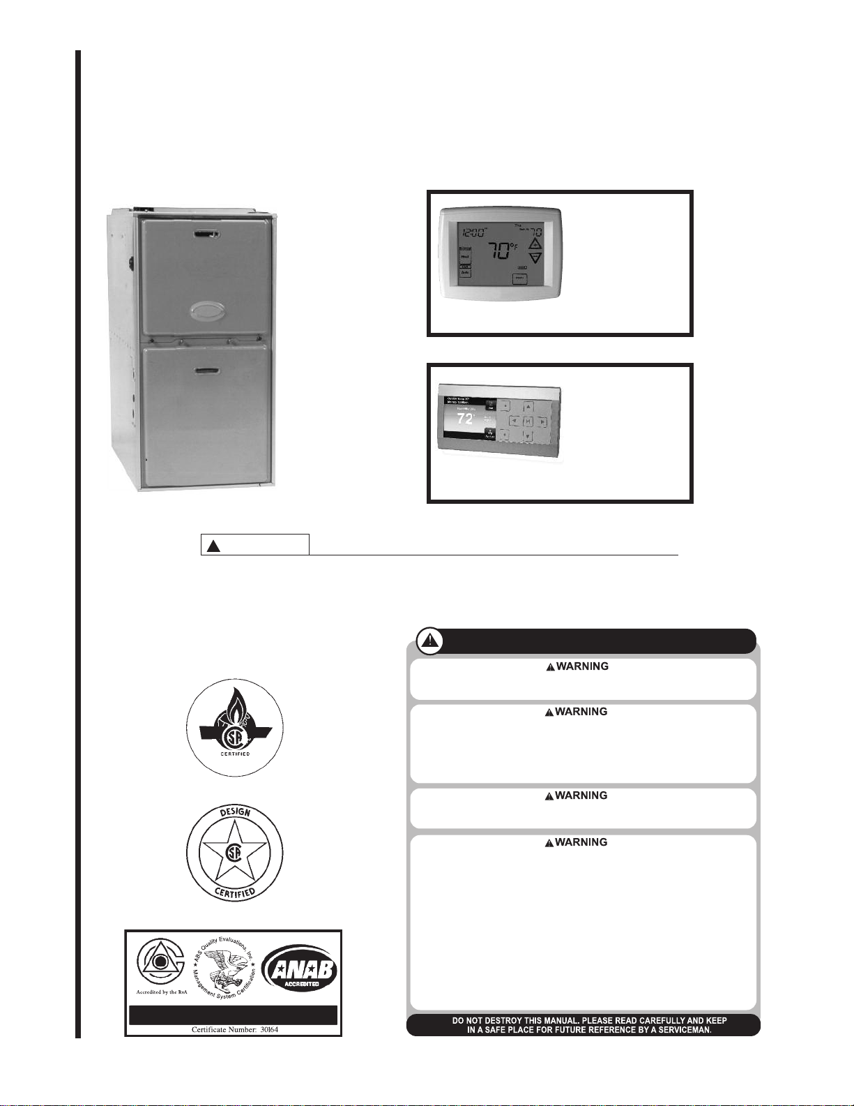
FOR RGFG UPFLOW HIGH EFFICIENCY MODULATING
CONDENSING GAS FURNACES
RGFG
MMOODDUULLAATTIINNG
TTHHEERRMMOOSSTTAAT
IINNSSTTAALLLLAATTIIOON
SSEEEE PPAAGGEE 9922
MMOODDUULLAATTIINNGG
CCOOMMMMUUNNIICCAATTIINNGG
TTHHEERRMMOOSSTTAATT
IINNSSTTAALLLLAATTIIOONN
SSEEEE PPAAGGEE 110066
WARNING
!
DO NOT EXCHANGE MEMORY CARDS BETWEEN FURNACES. DOING SO COULD RESULT IN
UNEXPECTED OPERATION – INCLUDING INADEQUATE AIRFLOW DURING HEATING (AND
OTHER MODES) OR A LOSS OF HEAT.
G
T
N
SUPERSEDES 92-24161-104-02
92-24161-104-03
Page 2

IMPORTANT: All Rheem products
meet current Federal OSHA Guidelines
for safety. California Proposition 65
warnings are required for certain products, which are not covered by the
OSHA standards.
California's Proposition 65 requires
warnings for products sold in California
that contain, or produce, any of over
600 listed chemicals known to the
State of California to cause cancer or
birth defects such as fiberglass insulation, lead in brass, and combustion
products from natural gas.
All “new equipment” shipped for sale in
California will have labels stating that
the product contains and/or produces
Proposition 65 chemicals. Although we
have not changed our processes, having the same label on all our products
facilitates manufacturing and shipping.
We cannot always know “when, or if”
products will be sold in the California
market.
You may receive inquiries from customers about chemicals found in, or
produced by, some of our heating and
air-conditioning equipment, or found in
natural gas used with some of our
products. Listed below are those chemicals and substances commonly associated with similar equipment in our
industry and other manufacturers.
• Glass Wool (Fiberglass) Insulation
• Carbon Monoxide (CO)
• Formaldehyde
• Benzene
More details are available at the
Websites for OSHA (Occupational
Safety and Health Administration), at
www.osha.gov
and the State of
California's OEHHA (Office of
Environmental Health Hazard
Assessment), at www.oehha.org.
Consumer education is important since
the chemicals and substances on the
list are found in our daily lives. Most
consumers are aware that products
present safety and health risks, when
improperly used, handled and maintained.
Installation Instructions are updated on
a regular basis. This is done as product
changes occur or if new information
becomes available. In this publication,
an arrow ➤ denotes changes from the
previous edition or additional new
material.
TABLE OF CONTENTS
SAFETY INFORMATION ..........................................................................................................................................3
INSTALLATION CHECK LIST...................................................................................................................................5
GENERAL INFORMATION.......................................................................................................................................6
IMPORTANT INFORMATION ABOUT EFFICIENCY AND INDOOR AIR QUALITY..............................................7
LOCATION REQUIREMENTS AND CONSIDERATIONS.......................................................................................8
CLEARANCE-ACCESSIBILITY......................................................................................................................9
SITE SELECTION...........................................................................................................................................9
DIMENSIONS AND CLEARANCE TO COMBUSTIBLES...........................................................................10
DUCTING.......................................................................................................................................................11
VENTING AND COMBUSTION AIR PIPING .........................................................................................................12
INSTALLATION WITH PRE-EXISTING VENT SYSTEMS..........................................................................12
JOINING PIPE AND FITTINGS....................................................................................................................12
CEMENTING JOINTS...................................................................................................................................13
NON-DIRECT VENT PIPE INSTALLATION...........................................................................................................14
DIRECT VENT PIPE INSTALLATION ....................................................................................................................18
CONCENTRIC TERMINATIONS..................................................................................................................20
CONDENSATE DRAIN / OPTIONAL NEUTRALIZER ..........................................................................................28
GAS SUPPLY AND PIPING....................................................................................................................................30
GAS VALVE...................................................................................................................................................31
LP CONVERSION.........................................................................................................................................33
ELECTRICAL WIRING............................................................................................................................................35
ACCESSORIES.......................................................................................................................................................37
ELECTRONIC AIR CLEANER......................................................................................................................37
HUMIDIFICATION AND DEHUMIDIFICATION............................................................................................37
OTHER ACCESSORIES ..............................................................................................................................39
TYPICAL WIRING ACCESSORIES FOR COMMUNICATING RESIDENTIAL SYSTEMS.................39
HIGH ALTITUDE INSTALLATIONS IN THE U.S....................................................................................................41
RGFG- HIGH ALTITUDE CONVERSION ....................................................................................................41
LP GAS AT HIGH ALTITUDE ELEVATIONS................................................................................................43
ZONING SYSTEMS......................................................................................................................................44
FURNACE INSTALLATION WITH NON-COMMUNICATING HIGH EFFICIENCY PREMIUM
COOLING OR HEAT PUMP SYSTEMS................................................................................................44
INTEGRATED FURNACE CONTROL ...................................................................................................................45
SEVEN SEGMENT DISPLAY.......................................................................................................................45
24 VAC THERMOSTAT INPUTS..................................................................................................................47
SPECIAL CONFIGURATION – COMM T-STAT AND NON-COMM CONDENSER..................................47
MEMORY CARD...........................................................................................................................................49
RULES FOR WRITING, DISTRIBUTION AND ARBITRATION OF MULTIPLE COPIES OF
FURNACE SHARED DATA FOR COMMUNICATING-CAPABLE FURNACES..............................49
REPLACING THE FURNACE CONTROL...................................................................................................51
DIPSWITCHES.............................................................................................................................................52
FURNACE OPERATION USING NON-COMMUNICATING MODULATING,
MODULATING AND TWO-STAGE T-STATS.....................................................................................55
COMMUNICATING SYSTEMS....................................................................................................................58
WIRING FOR COMMUNICATIONS...................................................................................................58
STARTUP FOR SYSTEMS CONFIGURED WITH COMMUNICATIONS........................................59
CONTINUOUS FAN OPERATION IN COMMUNICATING MODE...................................................60
ACTIVE FAULT CODES WITH COMMUNICATING SYSTEMS.......................................................60
FURNACE USER MENUS...........................................................................................................................60
STATUS 1............................................................................................................................................61
STATUS 2............................................................................................................................................63
2 WK HIST...........................................................................................................................................63
LIFE HIST............................................................................................................................................63
FAULT HISTORY.................................................................................................................................63
UNIT INFO...........................................................................................................................................63
SETUP.................................................................................................................................................63
DUAL-FUEL OPERATION............................................................................................................................65
START-UP PROCEDURES....................................................................................................................................66
SEQUENCE OF OPERATION.....................................................................................................................68
SETTING INPUT RATE................................................................................................................................68
MAINTENANCE.......................................................................................................................................................69
TROUBLESHOOTING CHART.........................................................................................................................72-73
NORMAL OPERATING CODES (TABLE 23)........................................................................................................74
FURNACE FAULT CODES WITH DESCRIPTIONS AND SOLUTIONS (TABLE 24)....................................75-90
WIRE DIAGRAM – STEPPER / SERVO MODULATING VALVE (FUEL CODES HA OR HB)...........................91
THERMOSTATS......................................................................................................................................................92
NON-COMMUNICATING THERMOSTATS.................................................................................................92
THERMOSTAT WIRING (WITH WIRING DIAGRAMS).........................................................................93-95
APPLICATIONS.......................................................................................................................................................96
MODULATING, TOUCH-SCREEN, NON-COMMUNICATING THERMOSTAT ((-)HC-TST412MDMS)....96
COMMUNICATING THERMOSTATS...................................................................................................................106
(-)HC-TST501CMMS PROGRAMMABLE COMMUNICATING THERMOSTAT......................................108
(-)HC-TST550CMMS FULL COLOR, PROGRAMMABLE COMMUNICATING THERMOSTAT.............112
VIEWING FURNACE USER MENUS WITH THE (-)HC-TST550CMMS THERMOSTAT.......................113
CHANGING FURNACE SETUP ITEMS ON THE (-)HC-TST550CMMS THERMOSTAT.......................114
IMPORTANT: To insure proper installation and operation of this product, completely read all instructions prior to attempting to assemble, install, operate, maintain or repair this product. Upon unpacking of the furnace, inspect all parts for
damage prior to installation and start-up.
2
Page 3

SAFETY INFORMATION
IMPORTANT!
THE COMMONWEALTH OF MASSACHUSETTS REQUIRES COMPLIANCE
WITH REGULATION 248 CMR 4.00
AND 5.00 FOR INSTALLATION OF
THROUGH-THE-WALL VENTED GAS
APPLIANCES AS FOLLOWS:
(a) For all side wall horizontally vented
gas fueled equipment installed in every
dwelling, building or structure used in
whole or in part for residential purposes,
including those owned or operated by
the Commonwealth and where the side
wall exhaust vent termination is less than
seven (7) feet above finished grade in
the area of the venting, including but not
limited to decks and porches, the following requirements shall be satisfied:
1. INSTALLATION OF CARBON
MONOXIDE DETECTORS. At the time of
installation of the side wall horizontal
vented gas fueled equipment, the
installing plumber or gasfitter shall
observe that a hard wired carbon
monoxide detector with an alarm and
battery back-up is installed on the floor
level where the gas equipment is to be
installed. In addition, the installing
plumber or gasfitter shall observe that a
battery operated or hard wired carbon
monoxide detector with an alarm is
installed on each additional level of the
dwelling, building or structure served by
the side wall horizontal vented gas
fueled equipment. It shall be the responsibility of the property owner to secure
the services of qualified licensed professionals for the installation of hard wired
carbon monoxide detectors.
a. In the event that the side wall horizontally vented gas fueled equipment is
installed in a crawl space or an attic, the
hard wired carbon monoxide detector
with alarm and battery back-up may be
installed on the next adjacent floor level.
b. In the event that the requirements of
this subdivision can not be met at the
time of completion of installation, the
owner shall have a period of thirty (30)
days to comply with the above requirements; provided, however, that during
said thirty (30) day period, a battery
operated carbon monoxide detector with
an alarm shall be installed.
2. APPROVED CARBON MONOXIDE
DETECTORS. Each carbon monoxide
detector as required in accordance with
the above provisions shall comply with
NFPA 720 and be ANSI/UL 2034 listed
and IAS certified.
3. SIGNAGE. A metal or plastic identification plate shall be permanently mounted to the exterior of the building at a
minimum height of eight (8) feet above
grade directly in line with the exhaust
vent terminal for the horizontally vented
gas fueled heating appliance or equipment. The sign shall read, in print size
no less than one-half (1/2) inch in size,
“GAS VENT DIRECTLY BELOW. KEEP
CLEAR OF ALL OBSTRUCTIONS”.
44..
INS
PECTION. T
inspector of the side wall horizontally
vented gas fueled equipment shall not
approve the installation unless, upon
inspection, the inspector observes carbon monoxide detectors and signage
installed in accordance with the provisions of 248 CMR 5.08(2)(a) 1 through
4.
(b) EXEMPTIONS: The following equip-
ment is exempt from 248 CMR
5.08(2)(a)1 through 4:
1. The equipment listed in Chapter 10
entitled “Equipment Not Required To Be
Vented” in the most current edition of
NFPA 54 as adopted by the Board; and
2. Product Approved side wall horizontally vented gas fueled equipment
installed in a room or structure separate from the dwelling, building or structure used in whole or in part for residential purposes.
(c) MANUFACTURER REQUIREMENTS – GAS EQUIPMENT VENTING SYSTEM PROVIDED. When the
manufacturer of Product Approved side
wall horizontally vented gas equipment
provides a venting system design or
venting system components with the
equipment, the instructions provided by
the manufacturer for installation of the
equipment and the venting system shall
include:
1. Detailed instructions for the installation of the venting system design or the
venting system components; and
2. A complete parts list for the venting
system design or venting system.
(d) MANUFACTURER REQUIREMENTS – GAS EQUIPMENT VENTING SYSTEM NOT PROVIDED. When
the manufacturer of a Product
Approved side wall horizontally vented
gas fueled equipment does not provide
the parts for venting the flue gases, but
identifies “special venting systems”, the
following requirements shall be satisfied by the manufacturer:
1. The referenced “special venting system” instructions shall be included with
the appliance or equipment installation
instructions; and
2. The “special venting systems” shall
be Product Approved by the Board, and
the instructions for that system shall
include a parts list and detailed installation instructions.
(e) A copy of all installation instructions
for all Product Approved side wall horizontally vented gas fueled equipment,
all venting instructions, all parts lists for
venting instructions, and/or all venting
design instructions shall remain with
the appliance or equipment at the completion of the installation.
he state or local gas
WARNING
!
INSTALL THIS FURNACE ONLY IN
A LOCATION AND POSITION AS
SPECIFIED IN THE LOCATION
REQUIREMENTS AND CONSIDERATIONS SECTION OF THESE
INSTRUCTIONS. PROVIDE ADEQUATE COMBUSTION AND VENTILATION AIR TO THE FURNACE
SPACE AS SPECIFIED IN THE
VENTING SECTION OF THESE
INSTRUCTIONS.
WARNING
!
PROVIDE ADEQUATE COMBUSTION AND VENTILATION AIR TO
THE FURNACE SPACE AS SPECIFIED IN THE COMBUSTION AND
VENTILATION AIR SECTION OF
THESE INSTRUCTIONS.
WARNING
!
COMBUSTION PRODUCTS MUST
BE DISCHARGED OUTDOORS.
CONNECT THIS FURNACE TO AN
APPROVED VENT SYSTEM ONLY,
AS SPECIFIED IN VENT PIPE
INSTALLATION SECTION OF
THESE INSTRUCTIONS.
WARNING
!
NEVER TEST FOR GAS LEAKS
WITH AN OPEN FLAME. USE A
COMMERCIALLY AVAILABLE
SOAP SOLUTION MADE SPECIFICALLY FOR THE DETECTION OF
LEAKS TO CHECK ALL CONNECTIONS, AS SPECIFIED IN GAS
SUPPLY AND PIPING SECTION OF
THESE TION INSTRUCTIONS.
WARNING
!
THIS FURNACE IS NOT
APPROVED OR RECOMMENDED
FOR INSTALLATION ON ITS BACK,
WITH ACCESS DOORS FACING
UPWARDS, OR WITH SUPPLY AIR
DISCHARGING TO THE RIGHTHAND SIDE WHEN FACING THE
FRONT OF THE FURNACE. SEE
FIGURE 3 FOR PROPER INSTALLATION OF HORIZONTAL MODELS.
WARNING
!
DO NOT INSTALL THIS FURNACE
IN A MOBILE HOME!! THIS FURNACE IS NOT APPROVED FOR
INSTALLATION IN A MOBILE
HOME. DOING SO COULD CAUSE
FIRE, PROPERTY DAMAGE, PERSONAL INJURY OR DEATH.
WARNING
!
USE ONLY WITH TYPE OF GAS
APPROVED FOR THIS FURNACE.
REFER TO THE FURNACE RATING
PLATE.
3
Page 4
WARNING
!
WHEN THIS FURNACE IS INSTALLED
IN A RESIDENTIAL GARAGE, IT
MUST BE INSTALLED SO THE BURNERS AND IGNITION SOURCE ARE
LOCATED NO LESS THAN 18 INCHES ABOVE THE FLOOR. THIS IS TO
REDUCE THE RISK OF IGNITING
FLAMMABLE VAPORS WHICH MAY
BE PRESENT IN A GARAGE.
ALSO, THE FURNACE MUST BE
LOCATED OR PROTECTED TO
AVOID PHYSICAL DAMAGE BY VEHICLES. FAILURE TO FOLLOW THESE
WARNINGS CAN CAUSE A FIRE OR
EXPLOSION, RESULTING IN PROPERTY DAMAGE, PERSONAL INJURY
OR DEATH.
WARNING
!
USE OF THIS FURNACE IS
ALLOWED DURING CONSTRUCTION
IF THE FOLLOWING TEMPORARY
INSTALLATION REQUIREMENTS
ARE MET. INSTALLATION MUST
COMPLY WITH ALL INSTALLATION
INSTRUCTIONS INCLUDING:
• PROPER VENT INSTALLATION;
• FURNACE OPERATING UNDER
THERMOSTATIC CONTROL;
• RETURN AIR DUCT SEALED TO
THE FURNACE;
• AIR FILTERS IN PLACE;
• SET FURNACE INPUT RATE AND
TEMPERATURE RISE PER RATING PLATE MARKING;
• MEANS FOR PROVIDING OUTDOOR AIR REQUIRED FOR COMBUSTION;
• RETURN AIR TEMPERATURE
MAINTAINED BETWEEN 55°F
(13°C) AND 80°F (27°C); AND;
• CLEAN FURNACE, DUCT WORK
AND COMPONENTS UPON SUBSTANTIAL COMPLETION OF THE
CONSTRUCTION PROCESS, AND
VERIFY FURNACE OPERATING
CONDITIONS INCLUDING IGNITION, INPUT RATE, TEMPERATURE RISE AND VENTING,
ACCORDING TO THE INSTRUCTIONS.
WARNING
!
DO NOT JUMPER OR OTHERWISE
BYPASS OVERTEMPERATURE OR
ANY OTHER LIMITS OR SWITCHES
ON THE FURNACE. IF ONE OF
THESE LIMITS OR SWITCHES
SHOULD TRIP OR OPEN, THE USER
IS TO BE INSTRUCTED TO CALL A
QUALIFIED INSTALLER, SERVICE
AGENCY OR THE GAS SUPPLIER.
FOR MANUALLY RESETABLE
SWITCHES, THE USER IS FURTHER
INSTRUCTED TO NEVER RESET THE
SWITCH, BUT TO CALL A QUALIFIED
TECHNICIAN. MANUAL RESET
SWITCHES MAY REQUIRE FURTHER
CORRECTIVE ACTIONS. FAILURE TO
FOLLOW THIS WARNING COULD
RESULT IN CARBON MONOXIDE
POISONING, SERIOUS INJURY OR
DEATH. IF THE UNIT IS INSTALLED
IN A CLOSET, THE DOOR MUST BE
CLOSED WHEN MAKING THIS
CHECK. INSTALLERS AND TECHNICIANS ARE INSTRUCTED TO
REPLACE ANY LIMIT OR SAFETY
SWITCH/DEVICE ONLY WITH IDENTICAL REPLACEMENT PARTS.
WARNING
!
DUCT LEAKS CAN CREATE AN
UNBALANCED SYSTEM AND DRAW
POLLUTANTS SUCH AS DIRT, DUST,
FUMES AND ODORS INTO THE
HOME CAUSING PROPERTY DAMAGE. FUMES AND ODORS FROM
TOXIC, VOLATILE OR FLAMMABLE
CHEMICALS, AS WELL AS AUTOMOBILE EXHAUST AND CARBON
MONOXIDE (CO), CAN BE DRAWN
INTO THE LIVING SPACE THROUGH
LEAKING DUCTS AND UNBALANCED DUCT SYSTEMS CAUSING
PERSONAL INJURY OR DEATH.
• IF AIR-MOVING EQUIPMENT OR
DUCTWORK IS LOCATED IN
GARAGES OR OFF-GARAGE
STORAGE AREAS - ALL JOINTS,
SEAMS, AND OPENINGS IN THE
EQUIPMENT AND DUCT MUST BE
SEALED TO LIMIT THE MIGRATION
OF TOXIC FUMES AND ODORS
INCLUDING CARBON MONOXIDE
FROM MIGRATING INTO THE LIVING SPACE.
• IF AIR-MOVING EQUIPMENT OR
DUCTWORK IS LOCATED IN
SPACES CONTAINING FUEL
BURNING APPLIANCES SUCH AS
WATER HEATERS OR BOILERS ALL JOINTS, SEAMS, AND OPENINGS IN THE EQUIPMENT AND
DUCT MUST ALSO BE SEALED TO
PREVENT DEPRESSURIZATION
OF THE SPACE AND POSSIBLE
MIGRATION OF COMBUSTION
BYPRODUCTS INCLUDING CARBON MONOXIDE INTO THE LIVING
SPACE.
WARNING
!
ALWAYS INSTALL FURNACE TO
OPERATE WITHIN THE FURNACE'S INTENDED TEMPERATURE-RISE RANGE WITH A DUCT
SYSTEM WHICH HAS AN EXTERNAL STATIC PRESSURE WITHIN
THE ALLOWABLE RANGE, AS
SPECIFIED IN DUCTING SECTION
OF THESE INSTRUCTIONS. SEE
ALSO FURNACE RATING PLATE.
WARNING
!
WWHHEENN AA FFUURRNNAACCEE IISS IINNSSTTAALLLLEEDD
SO THAT SUPPLY DUCTS CARRY
CIRCULATED BY THE FUR-
AIR
NACE TO AREAS OUTSIDE THE
SPACE CONTAINING THE FURNACE, THE RETURN AIR SHALL
ALSO BE HANDLED BY DUCT(S)
SEALED TO THE FURNACE CASING AND TERMINATING OUTSIDE
THE SPACE CONTAINING THE
FURNACE.
NOTICE
IMPROPER INSTALLATION, OR
INSTALLATION NOT MADE IN
ACCORDANCE WITH THE CSA
INTERNATIONAL (CSA) CERTIFICATION OR THESE INSTRUCTIONS, CAN RESULT IN UNSATISFACTORY OPERATION AND/OR
DANGEROUS CONDI-TIONS AND
ARE NOT COVERED BY THE UNIT
WARRANTY.
NOTICE
IN COMPLIANCE WITH RECOGNIZED CODES, IT IS RECOMMENDED THAT AN AUXILIARY
DRAIN PAN BE INSTALLED
UNDER ALL EVAPORATOR COILS
OR UNITS CONTAINING EVAPORATOR COILS THAT ARE LOCATED IN ANY AREA OF A STRUCTURE WHERE DAMAGE TO THE
BUILDING OR BUILDING CONTENTS MAY OCCUR AS A RESULT
OF AN OVERFLOW OF THE COIL
DRAIN PAN OR A STOPPAGE IN
THE PRIMARY CONDENSATE
DRAIN PIPING. SEE ACCESSORIES SECTION OF THESE
INSTRUCTIONS FOR AUXILIARY
HORIZONTAL OVERFLOW PAN
INFORMATION (MODEL RXBM).
WARNING
!
DO NOT EXCHANGE MEMORY
CARDS BETWEEN 2 OR MORE
DIFFERENT FURNACES. DOING
SO COULD RESULT IN UNEXPECTED OPERATION – INCLUDING INADEQUATE AIRFLOW DURING HEATING (AND OTHER
MODES OR A LOSS OF HEAT).
4
Page 5

INSTALLATION CHECK LIST
REFER TO INSTALLATION INSTRUCTIONS
GAS SUPPLY
Adequate pipe size
Correct supply pressure (during furnace operation)
Manifold pressure
No gas leaks
ELECTRICAL
115 V.A.C. supply (Single Circuit)
Polarity observed
Furnace properly grounded (Earth ground)
Adequate wire size
FURNACE INSTALLATION
Adequate clearance to combustibles
Adequate clearance for service (at front)
DUCT STATIC PRESSURE
in. w.c. on heating speed
in. w.c. on cooling speed
Air temperature rise
CONDENSATE LINE
Trap filled with water
Vented
Sloped toward drain
Condensate drain line hoses connected
and clamped
TERMINATIONS – DIRECT VENT
VERTICAL
Intake – 12" min. above roof/snow level
Correct relationship – exhaust to intake
VERTICAL – CONCENTRIC (RXGY-E03A)
Intake – 12" min. above roof/snow level
HORIZONTAL – STANDARD (RXGY-D02, -D02A, -D03,
-D03A)
Correct relationship – exhaust to intake
12" min. above grade/snow level
HORIZONTAL – ALTERNATE (RXGY-D02, -D02A, -D03,
-D03A, -D04 OR -D04A)
Correct relationship – exhaust to intake
Above anticipated snow level
HORIZONTAL – CONCENTRIC (RXGY-E03A)
12" min. above grade/snow level
Intake “Y” rotated above center
Exhaust sloped toward furnace
VENTING – NON-DIRECT VENT (VERTICAL ONLY)
in. diameter – exhaust pipe
ft. of pipe – exhaust
no. of elbows
TERMINATION – NON-DIRECT VENT (VERTICAL ONLY)
12" min. above roof/snow level
Freeze protection (if necessary)
Neutralizer (if needed)
VENTING – DIRECT VENT
in. diameter – intake pipe
in. diameter – exhaust pipe
ft. of pipe – intake air
no. of elbows – intake air
ft. of pipe – exhaust pipe
no. of elbows – exhaust pipe
Model #
Serial #
Date of installation
HORIZONTAL – STANDARD
12" min. above grade/snow level
HORIZONTAL – ALTERNATE
Above anticipated snow level
5
Page 6
GENERAL INFORMATION
The RGFG series furnaces are
design-certified by CSA for use with
natural and L.P. gases as follows:
• As direct vent, central forced air
furnaces with all combustion air
supplied directly to the furnace
burners through a special air intake
system outlined in these instructions.
• As non-direct, central forced air furnace taking combustion air from
the installation area or using air
ducted from the outside.
• IMPORTANT: Proper application,
installation and maintenance of this
furnace are required if consumers
are to receive the full benefits for
which they have paid.
Install this furnace in accordance with
the American National Standard
Z223.1 – latest edition entitled
“National Fuel Gas Code” (NFPA54,
90A and 90B) and requirements or
codes of the local utilities or other
authorities having jurisdiction. This is
available from the following:
National Fire Protection
Association, Inc.
Batterymarch Park
Quincy, MA 02269
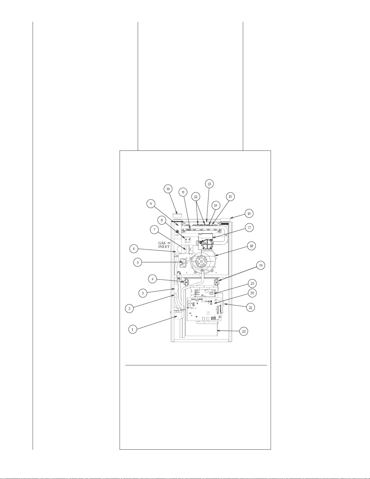
FIGURE 1
UPFLOW FURNACE RGFG
(GAS VALVE MAY BE DIFFERENT THAN SHOWN)
CSA International - U.S.
8501 East Pleasant Valley Road
Cleveland, Ohio, 44131
Canadian installations must be
installed in accordance with CSA,
local installation codes and
authorities having jurisdiction.
CSA is available from:
CSA International - Canada
178 Rexdale Blvd.
Etobicoke (Toronto), Ontario,
Canada M9W-1R3
ITEM
NO. PART NAME
1 CONDENSATE TRAP
2 DOOR SWITCH
3 JUNCTION BOX
4 TRANSFORMER
5 PRESSURE SWITCH ASSEMBLY
6 EXHAUST TRANSITION
7 CONNECTOR
8 MAIN LIMIT
9 EXHAUST AIR PIPE
10 VENT CAP SHIPPING PLUG
11 FLAME SENSOR
12 OVERTEMPERATURE SWITCH
ITEM
NO. PART NAME
13 TOP PLATE
14 BURNER
15 IGNITER
16 COMBUSTION AIR INLET
17 GAS VALVE
18 INDUCED DRAFT BLOWER
19 POWER FACTOR CHOKE
20 INTEGRATED FURNACE CONTROL
21 BLOWER MOTOR
22 BLOWER HOUSING
23 INDUCER CONTROL MODULE
ST-A1156-01
6
Page 7

IMPORTANT INFORMATION ABOUT EFFICIENCY
AND INDOOR AIR
QUALITY
Central cooling and heating equipment is only as efficient as the duct
system that carries the cooled or
heated air. To maintain efficiency,
comfort and good indoor air quality, it
is important to have the proper balance between the air being supplied
to each room and the air returning to
the cooling and heating equipment.
Proper balance and sealing of the
duct system improves the efficiency
of the heating and air conditioning
system and improves the indoor air
quality of the home by reducing the
amount of airborne pollutants that
enter homes from spaces where the
ductwork and / or equipment is located. The manufacturer and the U.S.
Environmental Protection Agency’s
Energy Star Program recommend
that central duct systems be checked
by a qualified contractor for proper
balance and sealing.
WARNING
!
DUCT LEAKS CAN CREATE AN
UNBALANCED SYSTEM AND
DRAW POLLUTANTS SUCH AS
DIRT, DUST, FUMES AND ODORS
INTO THE HOME CAUSING PROPERTY DAMAGE. FUMES AND
ODORS FROM TOXIC, VOLATILE
OR FLAMMABLE CHEMICALS, AS
WELL AS AUTOMOBILE EXHAUST
AND CARBON MONOXIDE (CO),
CAN BE DRAWN INTO THE LIVING
SPACE THROUGH LEAKING
DUCTS AND UNBALANCED DUCT
SYSTEMS CAUSING PERSONAL
INJURY OR DEATH (SEE FIGURE
2).
• IF AIR-MOVING EQUIPMENT OR
DUCTWORK IS LOCATED IN
GARAGES OR OFF-GARAGE
STORAGE AREAS - ALL JOINTS,
SEAMS, AND OPENINGS IN THE
EQUIPMENT AND DUCT MUST
BE SEALED TO LIMIT THE
MIGRATION OF TOXIC FUMES
AND ODORS INCLUDING CARBON MONOXIDE FROM MIGRATING INTO THE LIVING SPACE.
• IF AIR-MOVING EQUIPMENT OR
DUCTWORK IS LOCATED IN
SPACES CONTAINING FUEL
BURNING APPLIANCES SUCH
AS WATER HEATERS OR BOILERS - ALL JOINTS, SEAMS, AND
OPENINGS IN THE EQUIPMENT
AND DUCT MUST ALSO BE
SEALED TO PREVENT DEPRESSURIZATION OF THE SPACE
AND POSSIBLE MIGRATION OF
COMBUSTION BYPRODUCTS
INCLUDING CARBON MONOXIDE INTO THE LIVING SPACE.
NOTICE
IMPROPER INSTALLATION, OR
INSTALLATION NOT MADE IN
ACCORDANCE WITH THE CSA
INTERNATIONAL (CSA) CERTIFICATION OR THESE INSTRUCTIONS,
CAN RESULT IN UNSATISFACTORY
OPERATION AND/OR DANGEROUS
CONDI-TIONS AND ARE NOT COVERED BY THE UNIT WARRANTY.
NOTICE
IN COMPLIANCE WITH RECOGNIZED CODES, IT IS RECOMMENDED THAT AN AUXILIARY DRAIN PAN
BE INSTALLED UNDER ALL EVAPORATOR COILS OR UNITS CONTAINING EVAPORATOR COILS THAT ARE
LOCATED IN ANY AREA OF A
STRUCTURE WHERE DAMAGE TO
THE BUILDING OR BUILDING CONTENTS MAY OCCUR AS A RESULT
OF AN OVERFLOW OF THE COIL
DRAIN PAN OR A STOPPAGE IN THE
PRIMARY CONDENSATE DRAIN PIPING. SEE ACCESSORIES SECTION
OF THESE INSTRUCTIONS FOR
AUXILIARY HORIZONTAL OVERFLOW PAN INFORMATION (MODEL
RXBM).
FIGURE 2
MIGRATION OF DANGEROUS SUBSTANCES, FUMES, AND ODORS INTO LIVING SPACES
RECEIVING
Immediately upon receipt, all cartons
and contents should be inspected for
transit damage. Units with damaged
cartons should be opened immediately. If damage is found, it should
be noted on the delivery papers, and
a damage claim filed with the last
carrier.
• After unit has been delivered to
job site, remove carton taking care
not to damage unit.
• Check the unit rating plate for unit
size, electric heat, coil, voltage,
phase, etc. to be sure equipment
matches what is required for the
job specification.
• Read the entire instructions before
starting the installation.
• Some building codes require extra
cabinet insulation and gasketing
when unit is installed in attic applications.
• If installed in an unconditioned
space, apply caulking around the
power wires, control wires, refrigerant tubing and condensate line
where they enter the cabinet. Seal
the power wires on the inside
where they exit conduit opening.
Caulking is required to prevent air
leakage into and condensate from
forming inside the unit, control box,
and on electrical controls.
• Install the unit in such a way as to
allow necessary access to the
coil/filter rack and blower/control
compartment.
• Install the unit in a level position to
ensure proper condensate
drainage. Make sure unit is level in
both directions within 1/8”.
• Install the unit in accordance with
any local code which may apply
and the national codes. Latest edi-
tions are available from: “National
Fire Protection Association, Inc.,
Batterymarch Park, Quincy, MA
02269.” These publications are:
• ANSI/NFPA No. 70-(Latest Edition)
National Electrical Code.
• NFPA90A Installation of Air
Conditioning and Ventilating
Systems.
• NFPA90B Installation of warm air
heating and air conditioning systems.
• The equipment has been evaluated in accordance with the Code of
Federal Regulations, Chapter XX,
Part 3280.
7
Page 8
LOCATION REQUIREMENTS AND CONSIDERATIONS
GENERAL INFORMATION
!
CAUTION
DO NOT USE THIS FURNACE
DURING CONSTRUCTION IF
AIR LADEN CORROSIVE COMPOUNDS ARE PRESENT SUCH
AS CHLORINE AND FLUORINE.
OTHERWISE, PROVISIONS
MUST BE TAKEN TO PROVIDE
CLEAN, UNCONTAMINATED
COMBUSTION AND VENTILATION AIR TO THE FURNACE.
FURNACE COMBUSTION AND
VENTILATION AIR CONTAMINATED WITH THESE COMPOUNDS FORMS ACIDS DURING COMBUSTION WHICH CORRODES THE HEAT EXCHANGER
AND COMPONENT PARTS.
SOME OF THESE CONTAMINANTS ARE FOUND IN, BUT
NOT LIMITED TO, PANELING,
DRY WALL, ADHESIVES,
PAINTS, STAINS, VARNISHES,
SEALERS, AND MASONRY
CLEANING MATERIALS.
WARNING
!
DO NOT INSTALL THIS FURNACE IN A MOBILE HOME!!
THIS FURNACE IS NOT
APPROVED FOR INSTALLATION
IN A MOBILE HOME. DOING SO
COULD CAUSE FIRE, PROPERTY DAMAGE, PERSONAL
INJURY OR DEATH.
WARNING
!
WHEN THIS FURNACE IS
INSTALLED IN A RESIDENTIAL
GARAGE, IT MUST BE
INSTALLED SO THE BURNERS
AND IGNITION SOURCE ARE
LOCATED NO LESS THAN 18
INCHES ABOVE THE FLOOR.
THIS IS TO REDUCE THE RISK
OF IGNITING FLAMMABLE
VAPORS WHICH MAY
BE PRESENT IN A GARAGE.
ALSO, THE FURNACE MUST BE
LOCATED OR PROTECTED TO
AVOID PHYSICAL DAMAGE BY
VEHICLES. FAILURE TO FOLLOW THESE WARNINGS CAN
CAUSE A FIRE OR EXPLOSION,
RESULTING IN PROPERTY DAMAGE, PERSONAL INJURY OR
DEATH.
1. IMPORTANT: If installing the unit
over a finished ceiling or living
area, be certain to install an auxiliary condensate drain pan under
the entire unit. Extend this auxiliary drain pan under any evaporator coil installed with the furnace
and the open portion of the con-
densate drain assembly. See
“Condensate Drain/Neutralizer”
section for more details.
2. IMPORTANT: If using a cooling
evaporator coil with this furnace.
Be sure the air passes over the
heat exchanger before passing
over the cooling coil. The cooled
air passing over the warm ambient
air inside the heat exchanger
tubes can cause condensation
inside the tubes resulting in corrosion and eventual failure.
3. IMPORTANT: Install the furnace
level. If it is not level, condensate
cannot drain properly, possibly
causing furnace shut down.
NOTE: These furnaces are approved
for installation in attics, as well as
alcoves, utility rooms, closets and
crawlspaces. Make provisions to prevent freezing of condensate.
4. IMPORTANT: If this furnace is
installed in a garage, attic or any
other unconditioned space, a selfregulating heat tape must be
installed around the condensate
trap and along the entire length of
the condensate drain in the unconditioned space.
The heat tape should meet the following requirements:
a. The heat tape must be UL listed.
b. Install the heat tape per the
manufacturer’s instructions for
the entire length of drain pipe in
the unconditioned space.
c. The heat tape should be rated
at 3 or 5 watts per foot at 120V.
5. IMPORTANT: If installing in a
utility room, be sure the door is
wide enough to:
a. allow the largest part of the
furnace to pass; or
b. allow any other appliance
(such as a water heater)
to pass.
6. Install the furnace level and
plumb. If it is not level, condensate cannot drain properly, possibly causing furnace to shut
down.
IMPORTANT: Do not attempt to twin
the modulating furnace. The characteristics of the ECM blower motor
preclude twinning applications.
8
Page 9

FIGURE 3
REMOVING SHIPPING BRACKET
92-24379-01
CLEARANCE ACCESSIBILITY
The design of forced air furnaces with
models as listed in the tables under
Figure 4 are certified by CSA
Laboratories for the clearances to combustible materials shown in inches.
See name/rating plate and clearance
label for specific model number and
clearance information.
Service clearance of at least 24 inches
is recommended in front of
all furnaces.
FOR PURPOSES OF SERVICING
THIS APPLIANCE, ACCESSIBILITY
CLEARANCES, WHERE GREATER,
SHOULD TAKE PRECEDENCE OVER
FIRE PROTECTION CLEARANCES.
WARNING
!
FURNACES MUST NOT BE
INSTALLED DIRECTLY ON CARPET,
TILE OR OTHER COMBUSTIBLE
MATERIAL. INSTALLATION ON A
COMBUSTIBLE MATERIAL OTHER
THAN WOOD FLOORING MAY
RESULT IN FIRE CAUSING DAMAGE, PERSONAL INJURY OR
DEATH.
-GFG upflow furnaces and are
designed and certified for installation on combustible (wood only)
floors.
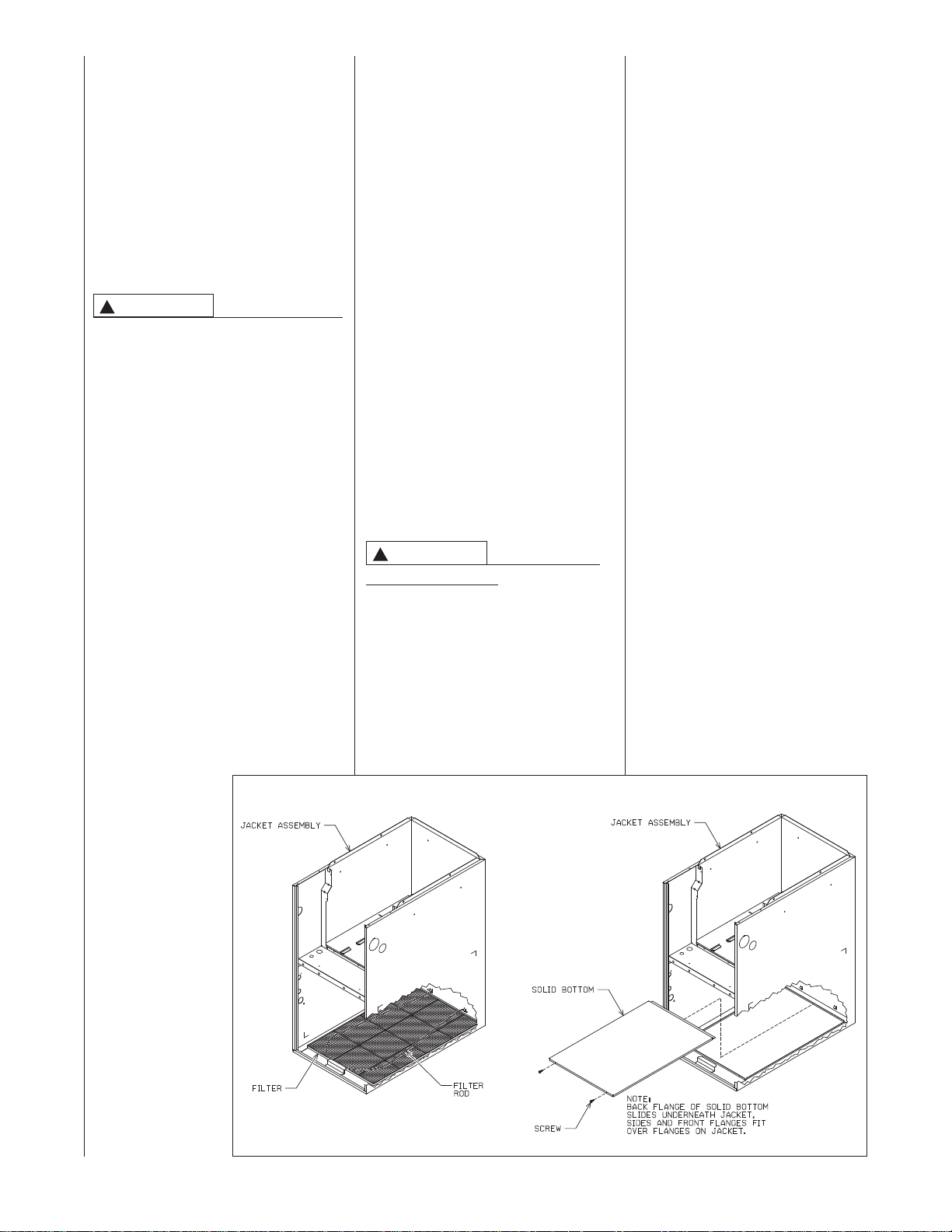
Upflow furnaces are shipped with
a bottom closure panel installed.
When bottom return air is used,
remove the panel by removing the
two screws attaching the panel to
the front base angle. See filter section for details (see Figure 5).
!
CAUTION
SOME MODELS HAVE A SHIPPING
BRACKET INSTALLED TO PROTECT THE BLOWER ASSEMBLY
DURING SHIPPING.
LOCATE AND REMOVE THE SHIPPING BRACKET FROM THE SIDE
OF THE BLOWER HOUSING
BEFORE OPERATING UNIT. SEE
FIGURE 3.
THE FOLLOWING MODELS
INCLUDE THE ADDITIONAL
BRACKET (WHICH MUST BE
REMOVED) ON THE BLOWER
ASSEMBLY:
RGFG-09EZCMS
RGFG-10EZCMS
RGFG-12ERCMS
SITE SELECTION
1. Select a site in the building near
the center of the proposed, or
existing, duct system.
2. Give consideration to the vent
system piping when selecting the
furnace location. Vent from the
furnace to the termination with
minimal length and elbows.
3. Locate the furnace near the
existing gas piping. If running a
new gas line, locate the furnace
to minimize the length and
elbows in the gas piping.
4. Locate the furnace to maintain
proper clearance to combustibles
as shown in Figure 4.
9
Page 10
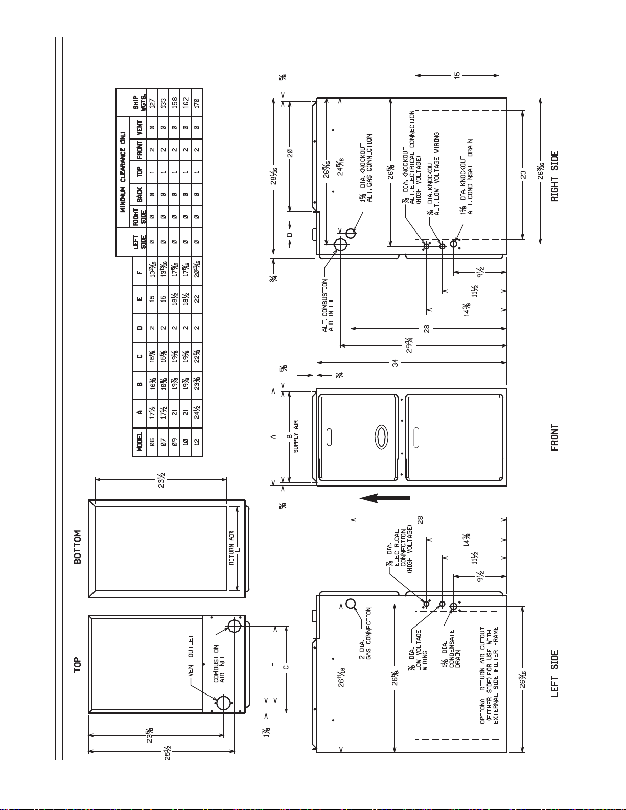
FIGURE 4
PHYSICAL DIMENSIONS AND CLEARANCE TO COMBUSTIBLES, UPFLOW MODELS
A039201
RGFG
UPFLOW MODELS
AIRFLOW
NOTE: For 1800 or more CFM, both side
returns must be used when not using a
bottom return configuration.
10
AO39201
Page 11
DUCTING
NOTE: FILTER AND FILTER-ROD ARE SHIPPED
ON TOP OF SOLID BOTTOM. REMOVE FILTER
AND FILTER ROD TO ACCES SOLID BOTTOM
Proper airflow is required for the correct
operation of this furnace.
Too little airflow can cause erratic operation and can damage the heat
exchanger. The supply and return duct
must carry the correct amount of air for
heating and cooling if summer air conditioning is used.
Size the ducts according to acceptable
industry standards and methods. The
total static pressure drop of the supply
and return duct should not exceed 0.2"
w.c.
WARNING
!
NEVER ALLOW THE PRODUCTS
OF COMBUSTION FROM THE
FLUE TO ENTER THE RETURN
AIR DUCTWORK OR THE CIRCULATED AIR SUPPLY. ALL RETURN
DUCTWORK MUST BE ADEQUATELY SEALED AND
SECURED TO THE FURNACE
WITH SHEET METAL SCREWS;
AND JOINTS, TAPED. SECURE
ALL OTHER DUCT JOINTS WITH
APPROVED CONNECTIONS AND
SEAL AIRTIGHT. WHEN A FURNACE IS MOUNTED ON A PLATFORM WITH RETURN THROUGH
THE BOTTOM, IT MUST BE
SEALED AIRTIGHT BETWEEN
THE FURNACE AND THE RETURN
AIR PLENUM. THE FLOOR OR
PLATFORM MUST PROVIDE
PHYSICAL SUPPORT OF THE
FURNACE WITHOUT SAGGING,
CRACKS, OR GAPS AROUND THE
BASE, PROVIDING A SEAL
BETWEEN THE SUPPORT AND
THE BASE.
FAILURE TO PREVENT PRODUCTS OF COMBUSTION FROM
BEING CIRCULATED INTO THE
LIVING SPACE CAN CREATE
POTENTIALLY HAZARDOUS CONDITIONS, INCLUDING CARBON
MONOXIDE POISONING THAT
COULD RESULT IN PERSONAL
INJURY OR DEATH.
DO NOT, UNDER ANY CIRCUMSTANCES, CONNECT RETURN OR
SUPPLY DUCTWORK TO OR
FROM ANY OTHER HEAT PRODUCING DEVICE SUCH AS A
FIREPLACE INSERT, STOVE, ETC.
DOING SO MAY RESULT IN FIRE,
CARBON MONOXIDE POISONING,
EXPLOSION, PERSONAL INJURY
OR PROPERTY DAMAGE.
IMPORTANT: Some high efficiency filters
have a greater than normal resistance to
airflow. This can adversely affect furnace
operation. Be sure to check airflow if
using any filter other than the factory-provided filter.
UPFLOW UNITS
1. Position the unit to minimize long
runs of duct or runs of duct with
many turns and elbows.
WARNING
!
UPFLOW FURNACE:
BASE PLATE MUST BE INSTALLED IN
THE FURNACE BOTTOM WHEN USING
SIDE AIR RETURN. FAILURE TO
INSTALL A BASE PLATE COULD
CAUSE THE PRODUCTS OF COMBUSTION TO CIRCULATE INTO THE LIVING
SPACE AND CREATE POTENTIALLY
HAZARDOUS CONDITIONS, INCLUDING CARBON MONOXIDE POISONING
OR DEATH.
A SOLID METAL
2. Open the return air compartment.
a. If using side return air, do not
remove the bottom base.
b. Cut an opening in the side .
The opening should be cut the
full width of the knockouts on
the unit.
NOTE: When using side
return, return air plenums,
RXGR-C17B, C21B and C24B
are available from the factory.
c. Remove the bottom base, if
using bottom return air.
Remove the panel by removing the two screws attaching
the base to the front base
angle. See Figure 5.
NOTE: Where the maximum
airflow is 1800 CFM or more,
both sides or the bottom must
be used for return air.
3. Connect the return duct or return
air cabinet to the unit. Make the
connection air tight to prevent
entraining combustion gases from
an adjacent fuel-burning appliance.
4. Be sure to have adequate
space for the unit filter.
NOTE: DO NOT take return air
from bathrooms, kitchens, furnace
rooms, garages, utility or laundry
rooms, or cold areas. DO NOT
use a rear air return.
5. If summer air conditioning is
desired, position the indoor coil on
the supply air side of the unit.
Insure that no air can bypass this
coil.
6. Connect the supply air plenum to
the furnace plenum opening.
IMPORTANT: If a flexible duct
connector must be used, it MUST
be rated for a minimum temperature of 250°F. continuous.
FIGURE 5
BOTTOM PANEL REMOVAL
ADS-5422-01
11
Page 12
VENTING AND COMBUSTION AIR PIPING
GENERAL INFORMATION
WARNING
!
READ AND FOLLOW ALL
INSTRUCTIONS IN THIS SECTION. FAILURE TO PROPERLY
VENT THIS FURNACE OR PROTECT IT FROM INADEQUATE
COMBUSTION AIR CAN CAUSE
CARBON MONOXIDE POISONING, AN EXPLOSION OR FIRE,
RESULTING IN PROPERTY DAMAGE, PERSONAL INJURY OR
DEATH.
OVER TEMPERATURE
SAFETY SWITCHES
Furnaces are equipped with safety
switches in the burner compartment to
protect against over temperature conditions. If a switch is tripped, it must be
manually reset.
WARNING
!
DO NOT JUMPER OVERTEMPERATURE OR ANY OTHER
SAFETY SWITCHES! IF ONE OF
THESE OVER TEMPERATURE
SWITCHES SHOULD TRIP, CALL
A QUALIFIED INSTALLER, SERVICE AGENCY OR THE GAS
SUPPLIER. DO NOT RESET THE
SWITCHES WITHOUT TAKING
CORRECTIVE ACTION. FAILURE
TO DO SO CAN RESULT IN CARBON MONOXIDE POISONING OR
DEATH. IF THIS UNIT IS
INSTALLED IN A CLOSET, THE
DOOR MUST BE CLOSED WHEN
MAKING THIS CHECK.
REPLACE THE OVER TEMPERATURE SAFETY SWITCHES ONLY
WITH THE IDENTICAL REPLACEMENT PART.
WARNING
!
IN CANADA, PRODUCTS CERTIFIED FOR INSTALLATION AND
INTENDED TO BE VENTED WITH
PLASTIC VENT SYSTEMS (PVC,
CPVC) MUST USE VENT SYSTEMS THAT ARE CERTIFIED TO
THE STANDARD FOR TYPE BH
GAS VENTING SYSTEMS, ULC
S636.
THE COMPONENTS OF THE
CERTIFIED MATERIAL MUST
NOT BE INTERCHANGED WITH
OTHER VENT SYSTEMS OR
UNLISTED PIPE/FITTINGS.
PLASTIC COMPONENTS AND
SPECIFIED PRIMERS AND
GLUES OF THE CERTIFIED SYSTEM MUST BE FROM A SINGLE
SYSTEM MANUFACTURER AND
NOT INTERMIXED WITH OTHER
SYSTEM MANUFACTURER’S
PARTS. EXCEPTIONS INCLUDE
THE RXGY-G02, RXGY-G02C
AND RXGY-E03A WHICH CAN BE
MIXED WITH OTHER MANUFACTURER’S COMPONENTS PROVIDED THEY ARE CONSTRUCTED FROM LIKE MATERIALS.
NOTE: INLET AIR PIPING IS NOT
CONSIDERED TO BE A PART OF
THE “VENTING SYSTEM”. THE
REQUIREMENT THAT VENT MATERIAL BE CERTIFIED TO ULC S636
DOES NOT APPLY TO INLET AIR
PIPING.
INSTALLATION WITH
PRE-EXISTING VENT
SYSTEMS
When the installation of this furnace
replaces an existing furnace that is
removed from a vent system serving
other appliances (such as a water
heater), the existing vent system is likely
to be too large to properly vent the
remaining attached appliances.
Follow the steps below with each appliance remaining connected to the original common vent system. Place the
appliance to be tested in operation,
while the other appliances remaining
connected to the common vent system
are not in operation. Test the operation
of each appliance individually by the following method.
1. Permanently seal any unused
openings in the common venting
system.
2. Visually inspect the venting system
for proper size and horizontal pitch
and determine that there is no
blockage, restriction, leakage, corrosion or other deficiencies which
could cause an unsafe condition.
3. If practical, close all building doors,
windows and all doors between the
space where the appliances
remaining connected to the common venting system are located.
Turn on clothes dryers and any
appliance not connected to the
common venting system. Turn on
any exhaust fans, such as range
hoods and bathroom exhausts, so
they will operate at maximum
speed. Do not operate a summer
exhaust fan. Close fireplace
dampers.
4. Follow the lighting instructions.
Place the appliance being inspected into operation. Adjust the thermostat so the appliance will operate
continuously.
5. Test for spillage at the draft hood
relief opening after 5 minutes of
main burner operation. Use the
flame of a match or candle, or
smoke from a cigarette, cigar
or pipe.
6. After it has been determined that
each appliance that remains connected to the common venting
system properly vents (when
tested as outlined above), return
doors, windows, exhaust fans,
fireplace dampers and any other
gas-burning appliance to their
previous conditions of use.
7. If improper venting is observed
during any of the above tests,
resize the common venting system. Refer to latest edition of the
National Fuel Gas Code ANSI
Z223.1, or the CSA-GAMA venting tables for Category I furnaces.
NOTE: For U.S. installations
only. Schedule 40 ABS-DWV
pipe and fittings may be used as
an alternate to PVC pipe for the
combustion air inlet and vent
pipes.
NOTE: For U.S. installations
only. Cellular core PVC is also
approved for use. It must be
schedule 40 PVC-DWV cellular
pipe manufactured under ASTM
F-891.
JOINING PIPE AND
FITTINGS
WARNING
!
PVC SOLVENT CEMENTS AND
PRIMERS ARE HIGHLY FLAMMABLE. PROVIDE ADEQUATE
VENTILATION AND DO NOT
ASSEMBLE COMPONENTS
NEAR HEAT SOURCE OR AN
OPEN FLAME. DO NOT
SMOKE. AVOID SKIN OR EYE
CONTACT. OBSERVE ALL
CAUTIONS AND WARNINGS
PRINTED ON MATERIAL CONTAINERS. FAILURE TO FOLLOW THESE GUIDELINES MAY
RESULT IN FIRE, EXPLOSION
OR ASPHYXIATION CAUSING
PERSONAL INJURY OR
DEATH.
In Canada, only approved vent materials, primers and solvents approved
to ULC S636 must be used for venting.
All pipe, fittings, solvent cement,
primers and procedures must conform to American National Standard
Institute and American Society for
Testing and Materials (ANSI/ASTM)
standards as shown below:
IMPORTANT: The plastic combustion
air and venting components are
MADE of PVC. If using ABS piping,
ensure that the solvent cement is
compatible for joining PVC to ABS
components or use a mechanical
connection that can withstand the
vent temperatures and is corrosion
resistant.
12
Page 13
CEMENTING JOINTS
EQUIVALENT VENTING – ASSIGNING VENT LENTGH TO
ELBOWS
This section applies to venting tables in both the NON-DIRECT and DIRECT VENT tables in this
book. Vent tables are provided only in equivalent length and do not reference elbows or a maximum
number of elbows. Instead, elbows are assigned a length as described below. The length determined
for each elbow is subtracted from the max vent length in the tables to determine how much straight
vent pipe (in ft) can still be used.
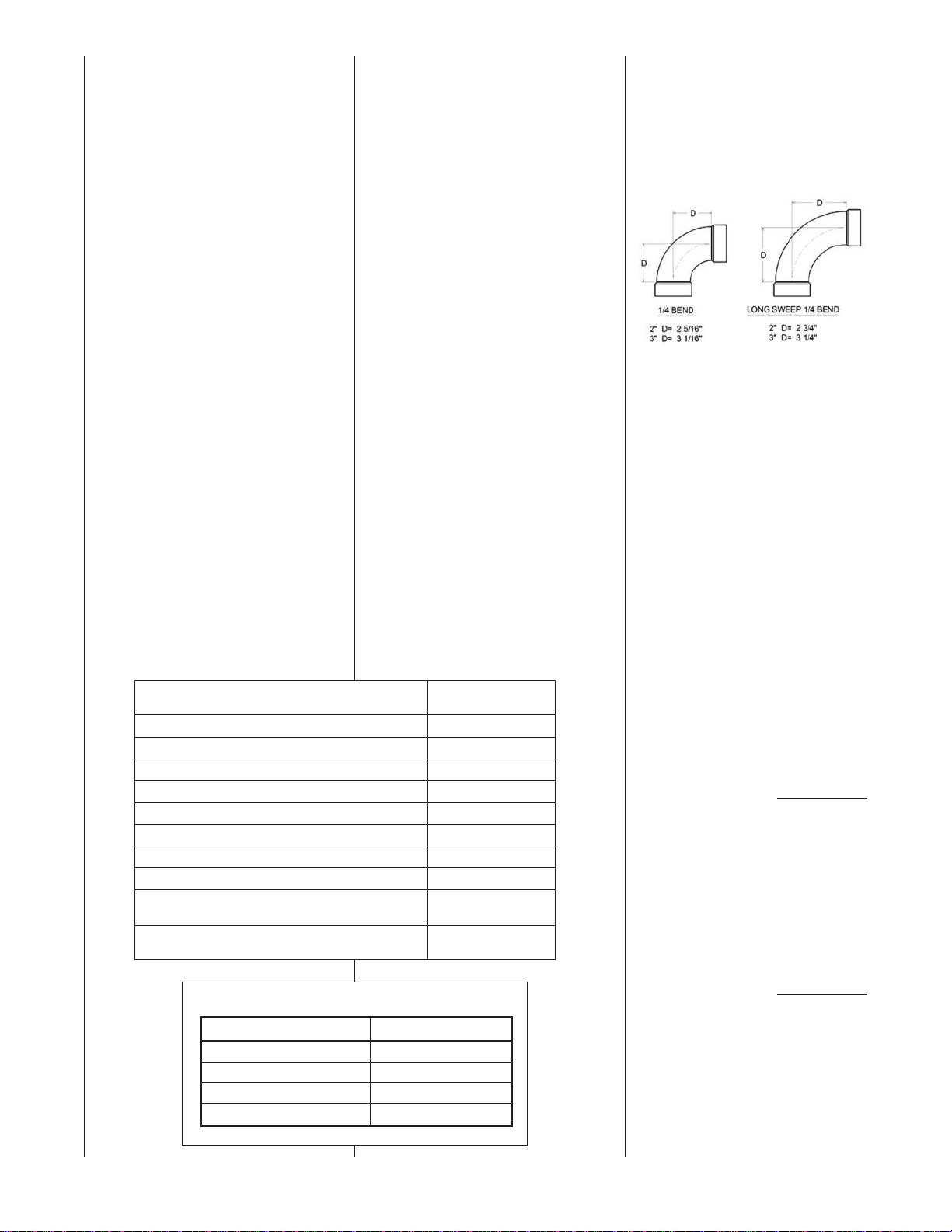
There are several different types of elbows that can be used for constructing a vent system. The
drawings below show the dimensions of common ¼ bend and ¼ bend long sweep 90 degree elbows
from ASTM 3311, Standard Specification for Drain, Waste and Vent (DWV) Plastic Fittings
Patterns.
A
long sweep ¼ bend 90 degree (long radius) elbow has an equivalent length of 5 feet of straight
pipe for either 2 or 3 inch plastic pipe. A standard 90° elbow has an equivalent length of 10 feet of
pipe. This equivalent length can be used in circumstances where it might be necessary to lengthen the
vent at the outside of the structure, such as in areas with large accumulations of snow in winter.
Table 1 shows the equivalent lengths of different types of elbows:
Table 1
Fitting Type Equivalent Length
45° Standard Elbow 5 feet of pipe
90° Standard Elbow 10 feet of pipe
45° Long-Sweep Elbow 2-1/2 feet of pipe
90° Long-Sweep Elbow 5 feet of pipe
Properly seal all joints in the PVC vent
using the following materials and procedures:
PVC CLEANER-PRIMER AND
PVC MEDIUM-BODY SOLVENT
CEMENT
NOTE: Follow vent manufacturer
instructions for ULC S636 vent installations.
IMPORTANT: After cutting pipe,
remove all ragged edges and burrs.
This is important to prevent increase
in pressure drop throughout the system.
1. Cut pipe end square. Chamfer
edge of pipe. Clean fitting socket
and pipe joint area of all dirt,
grease and moisture.
2. After checking pipe and socket
for proper fit, wipe socket and
pipe with cleaner-primer. Apply
a liberal coat of primer to inside
surface of socket and outside of
pipe. READ INSTRUCTIONS
INCLUDED WITH THE PRIMER
FOR PROPER INSTALLATION.
3. Apply a thin coat of cement evenly in the socket. Quickly apply a
heavy coat of cement to the pipe
end and insert pipe into fitting
with a slight twisting movement
until it bottoms out.
NOTE: Cement must be fluid; if
not, recoat with new cement.
4. Hold the pipe in the fitting for 30
seconds to prevent the tapered
socket from pushing the pipe out
of the fitting.
PIPE & FITTING MATERIAL
Schedule 40 PVC (Pipe) D1785
Schedule 40 PVC (Cellular Core Pipe) F891
Schedule 40 PVC (Fittings) D2466
SDR-21PVC (Pipe) D2241
SDR-26 PVC (Pipe) D2241
Schedule 40 ABS Cellular Core DWV (Pipe) F628
Schedule 40 ABS (Pipe) D1527
Schedule 40 ABS (Fittings) D2468
ABS-DWV (Drain Waste & Vent)
(Pipe & Fittings)
PVC-DWV (Drain Waste & Vent)
(Pipe & Fittings)
5. Wipe all excess cement from the
joint with a rag. Allow 15 minutes
before handling. Cure time varies
according to fit, temperature and
humidity.
NOTE: Stir the solvent cement frequently while using. Use a natural
bristle, one inch wide brush or the
applicator supplied with the can.
IMPORTANT: For Proper Installation DO
NOT use solvent cement that has
become curdled, lumpy or thickened.
DO NOT thin. Observe shelf precautions
printed on containers. For application
below 32°F, use only low-temperaturetype solvent cement.
For correct installation of the vent pipe,
follow the instructions provided by the
manufacturers of the pipe, primer and
solvent.
EQUIVALENT VENTING
––
ASSIGNING VENT
LENGTH TO ELBOWS
This section applies to venting tables in
both the NON-DIRECT and DIRECT
VENT tables in this book. Vent tables
are provided only in equivalent length
and do not reference elbows or a maximum number of elbows. Instead, elbows
are assigned a length as described
below. The length determined for each
elbow is subtracted from the max vent
length in the tables to determine how
much straight vent pipe (in ft) can still be
used.
ASTM
SPECIFICATION
D2661
D2665
There are several different types of
elbows that can be used for constructing a vent system. The drawings below show the dimensions of
common 1/4 bend and 1/4 bend long
sweep 90 degree elbows from ASTM
3311, Standard Specification for
Drain, Waste and Vent (DWV) Plastic
Fittings Patterns.
A long sweep 1/4 bend 90 degree
(long radius) elbow has an equivalent
length of 5 feet of straight pipe for
either 2 or 3 inch plastic pipe. A standard 90° elbow has an equivalent
length of 10 feet of pipe. This equivalent length can be used in circumstances where it might be necessary
to lengthen the vent at the outside of
the structure, such as in areas with
large accumulations of snow in winter. Table 1 shows the equivalent
lengths of different types of elbows:
With the equivalent length vent
concept a vent system can be
used any number of elbows and
length of straight pipe as long as
the maximum equivalent vent
length is not exceeded.
Example:
An RGFG-06 direct vent installation
needs a 31 foot long vent run with 5
elbows and 2 inch pipe.
31 feet of 2 inch pipe = 31
5 - 1/4 bend long sweep
elbows = 25
Since the maximum equivalent vent
length for an RGFG-06 is 60 feet, this
installation is acceptable.
If the same installation tried to use
standard elbows:
31 feet of 2 inch pipe = 31
5 - standard 90 degree
TABLE 1
And this installation is not acceptable
as it exceeds the 80 foot maximum
listed for the RGFG-06 model.
equivalent feet
equivalent feet
Total = 56
equivalent feet
equivalent feet
= 50
equivalent feet
Total = 81
equivalent feet
13
Page 14
NON-DIRECT VENT PIPE INSTALLATION
(FOR VERTICAL TERMINATIONS ONLY)
COMBUSTION AIR
WARNING
!
ALWAYS PROVIDE THIS FURNACE AND ANY OTHER FUEL
BURNING APPLIANCE WITH
ENOUGH FRESH AIR FOR
PROPER COMBUSTION AND
VENTILATION OF THE FLUE
GASES. MOST BUILDING
CODES REQUIRE THAT OUTSIDE AIR BE SUPPLIED INTO
THE FURNACE AREA. FAILURE TO DO SO CAN CAUSE
DEATH FROM CARBON
MONOXIDE POISONING.
Provide adequate facilities for combustion and ventilation air in accordance with section 5.3, Air for
Combustion and Ventilation of the
National Fuel Gas Code, ANSI
Z223.1 - latest edition; CAN/CGA
B149.1 and .2, or applicable provisions of the local building codes.
These combustion and ventilation
facilities must not be obstructed.
IMPORTANT: Air for combustion and
ventilation must not come from a
corrosive atmosphere. Any furnace
failure due to corrosive elements in
the atmosphere is excluded from
warranty coverage.
The following types of installation (but
not limited to the following) REQUIRE
OUTDOOR AIR for combustion, due
to chemical exposures:
• Commercial buildings
• Buildings with indoor pools
• Furnaces installed in laundry
rooms
• Furnaces in hobby or craft rooms
• Furnaces installed near chemical
storage areas.
Exposure to the following substances
in the combustion air supply (but not
limited to the following) also
REQUIRE OUTDOOR AIR for combustion:
• Permanent wave solutions
• Chlorinated waxes and cleaners
• Chlorine-based swimming pool
chemicals
• Water softening chemicals
• De-icing salts or chemicals
• Carbon Tetrachloride
• Halogen type refrigerants
• Cleaning solvents (such as perchloroethylene)
• Printing inks, paint removers,
varnishes, etc.
• Hydrochloric acid
• Cements and glues
• Anti-static fabric softeners for
clothes dryers
• Masonry acid washing materials
Combustion air must be free of acid
forming chemicals such as sulphur,
fluorine, and chlorine. These elements are found in aerosol sprays,
detergents, bleaches, cleaning solvents, air fresheners, paint and varnish removers, refrigerants and many
other commercial and household
products. Vapors from these products
when burned in a gas flame form acid
compounds. The acid compounds
increase the dew point temperature
of the flue products and produce
highly corrosive condensate.
WARNING
!
ALL FURNACE INSTALLATIONS
MUST COMPLY WITH THE
NATIONAL FUEL GAS CODE,
CAN/CSA B149.1 (CANADA) AND
LOCAL CODES TO PROVIDE ADEQUATE COMBUSTION AND VENTILATION AIR FOR THE FURNACE.
FAILURE TO DO SO CAN RESULT
IN EXPLOSION, FIRE, PROPERTY
DAMAGE, CARBON MONOXIDE
POISONING, PERSONAL INJURY
OR DEATH.
Combustion air requirements are
determined by whether the furnace
is in an open (unconfined) area or in
a confined space such as a closet or
small room.
FURNACE LOCATED IN AN
UNCONFINED SPACE
Using indoor air for combustion.
An unconfined space must have at
least 50 cubic feet for each 1,000
BTUH of the total input for all
appliances in the space. Here are a
few examples of the room sizes
required for different inputs. The
sizes are based on 8 foot ceilings.
See Table 2.
TABLE 2
UNCONFINED SPACE DIMENSIONS
BTUH Minimum Sq. Feet Typical Room Size
Input With 8 foot Ceiling
60,000 375 15' x 25' OR 19' x 20'
75,000 469 15' x 32' OR 20' x 24'
90,000 563 20' x 28' OR 24' x 24'
105,000 657 20' x 33' OR 26' x 25'
120,000 750 25' x 30' OR 24' x 32'
If the open space containing the furnace is in a building constructed to
severely limit outside air infiltration
(contemporary energy efficient construction methods), outside air may
still be required for the furnace to
operate and vent properly. Outside
air openings should be sized the
same as for a confined space.
14
Page 15

FURNACE LOCATED IN A
CONFINED SPACE.
A confined space (any space smaller than shown before as “unconfined”) must have openings into
the space, which are located in
accordance with the requirements set forth in the following
subsections A and B. The open-
ings must be sized by how they
connect to the heated area or to the
outside, and by the input of all
appliances in the space.
If the confined space is within a
building with tight construction,
combustion air must be taken from
outdoors or areas freely communicating with the outdoors.
TABLE 3
INDOOR AIR OPENING DIMENSIONS
BTUH Free Area
Input Each Opening
60,000 100 square inches
75,000 100 square inches
90,000 100 square inches
105,000 105 square inches
120,000 120 square inches
FIGURE 6
AIR FROM HEATED SPACE
A. USING INDOOR AIR FOR
COMBUSTION
IMPORTANT: DO NOT take air from
a heated space with a fireplace,
exhaust fan or other device that may
produce a negative pressure.
If combustion air is taken from the
heated area (see Figure 6), the
openings must each have at least
100 square inches of free area.
Each opening must have at least
one square inch of free area for
each 1,000 BTUH of total input in
the space. See Table 3.
B. USING OUTDOOR AIR FOR
COMBUSTION
IMPORTANT: Do not take air from
an attic space that is equipped with
power ventilation.
The confined space must communicate with the outdoors in accordance
with Methods 1 or 2. The minimum
dimension of air openings shall not
be less than 3 inches. Where ducts
are used, they shall be of the same
cross-sectional area as the free area
of the openings to which they connect.
Method 1
Two permanent openings, one located within 12 inches of the top and
one located within 12 inches of the
bottom of the enclosure, shall be provided. The openings shall communicate directly, or by ducts, with the outdoors or spaces (crawl or attic) that
freely communicate with the outdoors.
a. Where directly communicating
with the outdoors or where communicating to the outdoors
through vertical ducts as shown in
Figure 7, each opening shall have
a minimum free area of 1 square
inch for each 4000 BTUH of total
appliance input rating in the
enclosure. See Table 4.
A077501
TABLE 4
VERTICAL OUTDOOR AIR OPENING
DIMENSIONS
BTUH Free Area Round Pipe
Input Each Opening Size
60,000 15.00 square inches 5"
75,000 18.75 square inches 5"
90,000 22.50 square inches 6"
105,000 26.25 square inches 6"
120,000 30.00 square inches 7"
15
Page 16
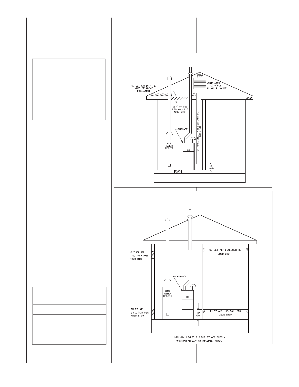
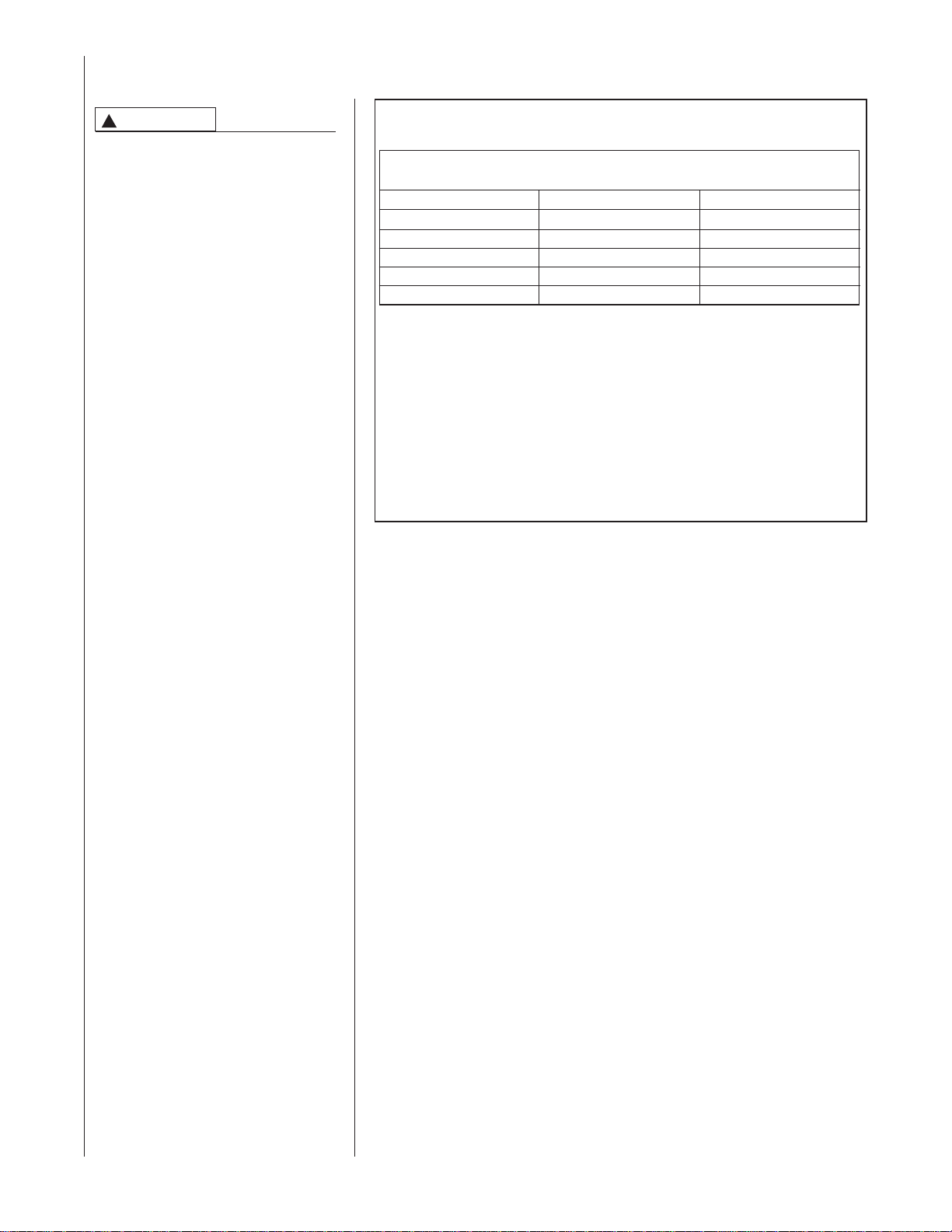
b. Where communicating with out-
doors through horizontal ducts,
each opening shall have a minimum
free area of 1 square inch for each
2000 BTUH of total input rating of
all equipment in the enclosure. See
Table 5 and Figure 8.
TABLE 5
HORIZONTAL OUTDOOR AIR
OPENING DIMENSIONS
BTUH Free Area Round Pipe
Input Each Opening Size
60,000 30.00 square inches 7"
75,000 37.50 square inches 7"
90,000 45.00 square inches 8"
105,000 52.50 square inches 9"
120,000 60.00 square inches 9"
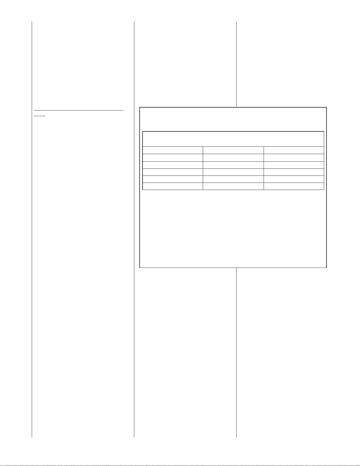
Method 2
One permanent opening, located
within 12 inches of the top of the
enclosure, shall be permitted where
the equipment has clearances of at
least 1 inch from the sides and back
and 6 inches from the front of the
appliance. The opening shall directly
communicate with the outdoors or
communicate through a vertical or
horizontal duct to the outdoors or
spaces (crawl or attic) that freely
communicate with the outdoors, and
shall have a minimum free area of:
a. One square inch for each 3000
BTUH of the total input rating of
all equipment located in the
enclosure (see Table 6), and
Combustion air openings must not be
restricted in any manner.
CONSULT LOCAL CODES FOR SPECIAL REQUIREMENTS.
FIGURE 7
AIR FROM ATTIC/CRAWL SPACE
A077601
FIGURE 8
OUTSIDE AIR USING A HORIZONTAL INLET & OUTLET
b. Not less than the sum of the
areas of all vent connectors in the
confined space.
If the unit is installed where there is
an exhaust fan, sufficient ventilation
must be provided to prevent the
exhaust fan from creating a negative
pressure.
TABLE 6
VERTICAL OR HORIZONTAL
OUTDOOR AIR OPENING DIMENSIONS
BTUH Free Area Round Pipe
Input Each Opening Size
60,000 20.00 square inches 6"
75,000 25.00 square inches 6"
90,000 30.00 square inches 7"
105,000 35.00 square inches 7"
120,000 40.00 square inches 8"
16
A077701
Page 17
INSTALLATION GUIDELINES
IMPORTANT: When installed as a non-
direct furnace, only vertical terminations
are allowed. Do not use horizontal terminations when the furnace is installed with
a non-direct vent.
All exhaust vent piping must be installed
in compliance with Part 7, Venting of
Equipment, of the latest edition of the
National Fuel Gas Code NFPA 54/ANSI
A223.1, or CAN/CGA-B149.1 and .2,
local codes or ordinances and these
instructions.
7. The minimum vent length is 5 feet.
8. All piping through the roof is 2".
When using 3" pipe on 90, 105
and 120 kBtu furnaces, reduce
to 2" within 18" of the inside of
the roof.
9. Vertical through-the-roof installations do not require any special
vent termination. Use 2" PVC
pipe extending a minimum of 12
inches above the anticipated
maximum level of snow accumulation.
In Canada, the pipe must extend a
minimum of 18” above the roof or
maximum 24” above the roof without supports.
10. No screens may be used to
cover combustion air or
exhaust.
VVEENNTTIINNGG GGUUIIDDEELLIINNEESS -- NNoonn--DDiirreecctt
VVeenntt
1. IMPORTANT: Do not common vent
with any other appliance. Do not
install in the same chase or chimney with a metal or high temperature plastic pipe from another gas or
fuel-burning appliance unless the
required minimum clearances to
combustibles are maintained
between the PVC pipe and other
pipes.
2. Use only medium or long radius
sweep elbows, such as PVC-DWV
elbows.
3. Vertical vent piping is preferred.
4. Install all horizontal piping as follows:
• Slope horizontal vent piping
upward a minimum of 1/4" per
foot of run so that condensate
drains toward the furnace.
• Support horizontal vent piping at
least every four feet. No sags or
dips are permitted.
5. Insulate all vent runs through
unconditioned spaces where belowfreezing temperatures are expected,
with 1" thick medium density, foil
faced fiber glass or equivalent
Rubatex/Armaflex insulation. For
horizontal runs where water may
collect and freeze, wrap the vent
pipe with self-regulating, 3 or 5 Watt
heat tape. The heat tape must be
U.L. listed and installed per the
manufacturer’s instructions.
6. All piping between the furnace and
the roof penetration is 2" or 3" as
specified in Table 7. Table 7 lists the
maximum allowable exhaust vent
pipe length for the number of
elbows used, based on the furnace
size.
IMPORTANT: Use Only standard
vertical terminations when installing
the modulating furnace as a nondirect vent appliance.
➤ TABLE 7
NON-DIRECT VENT APPLICATIONS
MAXIMUM ALLOWABLE LENGTH IN FEET OF EXHAUST PIPE
MAX EQUIVALENT VENT FOR UPFLOW RFGF FURNACES
(See Eq. Vent section on Page 13)
Model
2” Non-Direct Vent
3” Non-Direct Vent
RGFG-06EMCKS 80’ 80’
RGFG-07EMCKS 80’ 80’
RGFG-09EZCMS NR 80’
RGFG-10EZCMS NR 80’
RGFG-12ERCMS NR 80’
NOTES:
1. N.R. - NOT RECOMMENDED.
2. MAXIMUM OF 6 ELBOWS MAY BE USED. DO NOT COUNT ELBOWS IN ALTERNATE TERMINATION KIT.
MEDIUM OR LONG SWEEP ELBOWS MAY BE USED.
3. A 45 OR 22.5 DEGREE ELBOW IS CONSIDERED ONE ELBOW.
4. CONCENTRIC TERMINATION NO. RXGY-E03A IS FOR THRU-THE-ROOF OR THRU-THE-WALL VENTING.
5. USE KITS RXGY-D02 OR D02A (2") OR RXGY-D03 OR D03A (3") FOR STANDARD OR ALTERNATE
THRU-THE-WALL VENTING.
6. USE KITS RXGY-D04 OR D04A FOR ALTERNATE VENTING OF 120,000 BTUH UNITS WITH LONG RUNS.
7. NO SCREENS MAY BE USED TO COVER COMBUSTION AIR AND EXHAUST.
1
⁄2” CABINET WIDTH
* A = 17
B = 21” CABINET WIDTH
8. ALL HORIZONTAL VENTING MUST BE DONE WITH DIRECT VENTING (2-PIPE). FURNACES INSTALLED
AS NON-DIRECT VENT MUST BE TERMINATED VERTICALLY.
17
Page 18
DIRECT VENT PIPE INSTALLATION
WARNING
!
READ AND FOLLOW ALL
INSTRUCTIONS IN THIS SECTION. FAILURE TO PROPERLY
VENT THIS FURNACE CAN
CAUSE CARBON MONOXIDE
POISONING OR AN EXPLOSION
OR FIRE, RESULTING IN PROPERTY DAMAGE, PERSONAL
INJURY OR DEATH.
Direct vent installations require a dedicated combustion air and venting system. All air for combustion is taken
from outside and all combustion products are discharged to the outdoors.
Therefore, no ventilation or combustion air openings are required.
INSTALLATION
GUIDELINES
All exhaust piping must be installed in
compliance with Part 7, “Venting of
Equipment,” of the latest edition of the
National Fuel Gas Code NPFA 54,
90A, 90B ANSI Z223.1-, CAN/CSA
B149.1 (Canada), local codes or ordinances and these instructions.
1. IMPORTANT: Do not common
vent with any other appliance. Do
not install in the same chase or
chimney with a metal or high temperature plastic pipe from another
gas or fuel-burning appliance
unless the required minimum
clearances to combustibles are
maintained between the approved
PVC pipe and other pipes.
2. Use only medium or long radius
sweep elbows.
NOTE: For all installations. Extend
the combustion air exhaust pipe a
minimum of 18" vertically above
the furnace cabinet before turning
the vent.
3. Vertical piping is preferred.
4. Install all horizontal piping as follows:
• Slope horizontal vent piping
upward a minimum of 1/4" per foot
of run so that condensate drains
toward the furnace.
• Support horizontal vent piping at
least every four feet. No sags or
dips are permitted.
In Canada, refer to manufacturer’s
instructions for supporting ULC S636
venting.
➤ TABLE 8
DIRECT VENT APPLICATIONS
MAXIMUM ALLOWABLE LENGTH IN FEET OF EACH EXHAUST PIPE AND INTAKE PIPE
MAX EQUIVALENT VENT FOR UPFLOW RFGF FURNACES
(See Eq. Vent section on Page 13)
Model
2” Direct Vent
3” Direct Vent
RGFG-06EMCKS 80’ 80’
RGFG-07EMCKS 80’ 80’
RGFG-09EZCMS NR 80’
RGFG-10EZCMS NR 80’
RGFG-12ERCMS NR 80’
NOTES:
1. N.R. - NOT RECOMMENDED.
2. MAXIMUM OF 6 ELBOWS MAY BE USED. DO NOT COUNT ELBOWS IN ALTERNATE TERMINATION KIT.
MEDIUM OR LONG SWEEP ELBOWS MAY BE USED.
3. A 45 OR 22.5 DEGREE ELBOW IS CONSIDERED ONE ELBOW.
4. CONCENTRIC TERMINATION NO. RXGY-E03 IS FOR THRU-THE-ROOF OR THRU-THE-WALL VENTING.
5. USE KITS RXGY-DO2 (2") OR RXGY-D03 (3") FOR STANDARD OR ALTERNATE THRU-THE-WALL
VENTING.
6. USE KITS RXGY-D04 FOR ALTERNATE VENTING OF 120,000 BTUH UNITS WITH LONG RUNS.
7. NO SCREENS MAY BE USED TO COVER COMBUSTION AIR AND EXHAUST.
1
⁄2” CABINET WIDTH
* A = 17
B = 21” CABINET WIDTH
** ALTERNATE VENT NOT PERMITTED ON DOWNFLOW/HORIZONTAL MODELS.
8. ALL HORIZONTAL VENTING MUST BE DONE WITH DIRECT VENTING (2-PIPE). FURNACES
INSTALLED AS NON-DIRECT VENT MUST BE TERMINATED VERTICALLY.
18
Page 19
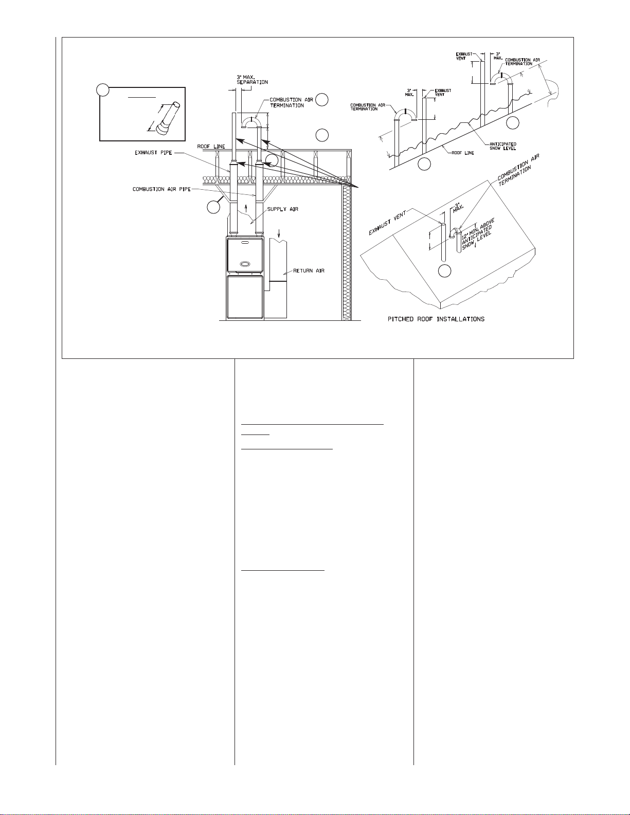
FIGURE 9
12” MIN.
SEPARATION
12” MIN.
ROOF LEVEL
12” MIN. U.S.
18” MIN. CANADA
SEPARATION
12” MIN.
SEPARATION
12” MIN.
SEPARATION
12” MIN. U.S.
18” MIN. CANADA
SEPARATION
12” MIN.
SEPARATION
CANADA:
MINIMUM 18”
ABOVE ROOF
OR 24”
MAXIMUM
ABOVE ROOF
WITHOUT
SUPPORT
STANDARD VERTICAL DIRECT VENTING
UPFLOW MODEL SHOWN (TYPICAL FOR DOWNFLOW/HORIZONTAL MODELS)
5
DETAIL A
EXHAUST
TERMINATION
(90, 105 & 120K
MODELS)
12”
1
2
5
NOTES:
THE COMBUSTION AIR PIPE
1
MUST TERMINATE IN THE
SAME PRESSURE ZONE AS
THE EXHAUST PIPE.
INCREASE THE 12-IN. MINIMUM
2
TO KEEP TERMINAL OPENING ABOVE
ANTICIPATED LEVEL OF SNOW ACCUMULATION WHERE APPLICABLE.
WHEN 3-IN. DIAM. PIPE IS USED,
3
REDUCE TO 2-IN. DIAMETER BEFORE
PENETRATING ROOF. A MAXIMUM OF
18 IN. OF 2-IN. PIPE MAY BE USED
BEFORE PASSING THROUGH ROOF.
SUPPORT VERTICAL PIPE EVERY 6
4
FEET.
EEXXHHAAUUSSTT TTEERRMMIINNAATTIIOONN -- TTEERRMMIINNAATTEE
5
TTHHEE LLAASSTT 1122 IINNCCHHEESS WWIITTHH 22” PPVVCC
PPIIPPEE OONN 9900,,000000 AANNDD 112200,,000000 BBTTUUHH
MMOODDEELLSS..
SSEEEE DDEETTAAIILL AA..
5. Insulate all vent runs through
unconditioned spaces where
below-freezing temperatures are
expected with 1" thick medium
density, foil faced fiber glass or
equivalent Rubatex/Armaflex insulation. For horizontal runs where
water may collect, wrap the vent
pipe with self-regulating, 3 or 5
Watt heat tape. The heat tape
must be U.L. listed and installed
per the manufacturer’s instructions.
6. All piping between the furnace
and the roof or outside wall penetration is 2" or 3" as specified in
Table 8. Table 8 lists the maximum allowable length for the
exhaust vent pipe and intake air
pipe for the number of elbows
used, based on the type of termination and furnace size.
7. The minimum vent length is 5
feet for any termination.
8. All piping through the roof or outside wall is 2". When using 3"
pipe, reduce to 2" within 18" of
the inside of the roof or outside
wall (except 120,000 BTUH
model using the RXGY-D04 or
D04A Horizontal Vent Kit).
9. Terminate the vent using one of
the following termination options.
3
4
10. No screens may be used to cover
combustion air or exhaust.
VERTICAL TERMINATIONS
STANDARD VERTICAL TERMINATIONS
Combustion Air Piping
um-radius sweep elbows to keep the
inlet downward and prevent the entry of
rain. The inlet opening of the com-
bustion air termination must be a
minimum of 12" above the anticipated level of snow accumulation.
In Canada, the inlet pipe must extend a
minimum of 18” above the roof or a
maximum of 24” above the roof without
support.
Exhaust Vent Piping
must terminate at least 12 inches
above the combustion air termination
inlet. The maximum length of the
exposed vent pipe above the roof is
30".
(See Figure 9)
: Use two medi-
: The exhaust vent
PIPE REDUCTION
NOT REQUIRED ON
60 & 75K BTU MODELS
5
5
ST-A0407-00
19
Page 20
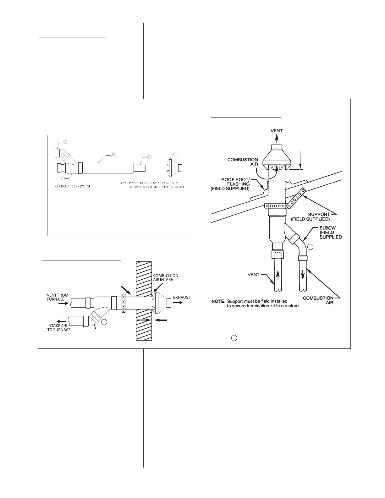
CONCENTRIC TERMINATIONS
CCOONNCCEENNTTRRIICC VVEENNTT KKIITT
NNOO.. RRXXGGYY--EE0033AA ((SSEEEE FFIIGGUURREE 1100))
This kit is for vertical and horizontal
intake air/vent runs. One
5-in. diameter hole is required for
installation. See Figure 10 for the general layout. Complete installation
instructions are included with the kit.
FIGURE 10
CONCENTRIC VENT KIT NO. RXGY-E03A
(DIRECT VENT INSTALLATIONS)
ITEM No. DESCRIPTION
1 2.5
2 4
33
43
5 PVC RAINCAP
" PVC PIPE SCHEDULE 40 -- 37.125" LONG
" PVC PIPE SCHEDULE 40 -- 24" LONG
" x 3" x 4" SPECIAL CONCENTRIC FITTING
" x 45° STREET ELBOW (FIELD SUPPLIED)
NNOOTTEE::
The following IPEX brand concentric terminations (System 636) may
be purchased in the field
and used in
place of factory supplied kits:
3” Concentric Kit – Item # 196006
VVEERRTTIICCAALL IINNSSTTAALLLLAATTIIOONN
MAINTAIN 12 IN.
MINIMUM CLEARANCE
ABOVE HIGHEST
ANTICIPATED SNOW
LEVEL. MAXIMUM OF
24 IN. ABOVE ROOF.
In Canada, maintain a
minimum distance of 18”
above the roof or 24”
maximum without
additional support.
HHOORRIIZZOONNTTAALL IINNSSTTAALLLLAATTIIOONN
FFIIEELLDD--SSUUPPPPLLIIEEDD
SSTTRRAAPP
A
NOTE: AIR
ORIENTATION SENSITIVE.
INTAKE NOT
11"" MMAAXXIIMMUUMM
A
A
NOTE: Drain tee is not needed for the inlet pipe.
20
Page 21
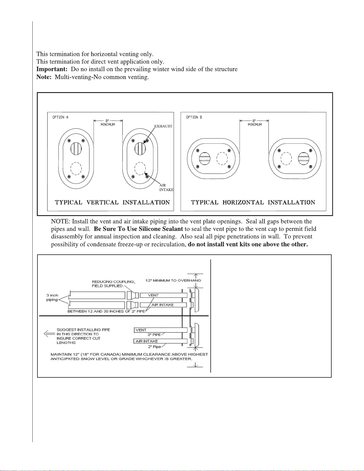
INSTALLATION – RXGY-G02(U.S.) & RXGY-G02C (Canada certified to
ULC S636) Side Wall Vent
FIGURE 11
VENT KIT INSTALLATION OPTIONS
FIGURE 12
TYPICAL INSTALLATION
For all models installed with 3” pipereduce to a length between 12 inches
and 30 inches of 2 inch pipe.
Note: Vent should protrude a
maximum of 2-1/4” beyond vent plate.
Air intake should protrude a maximum
of 1 inch beyond vent plate.
Seal all wall cavities.
ST-A1075
21
Page 22
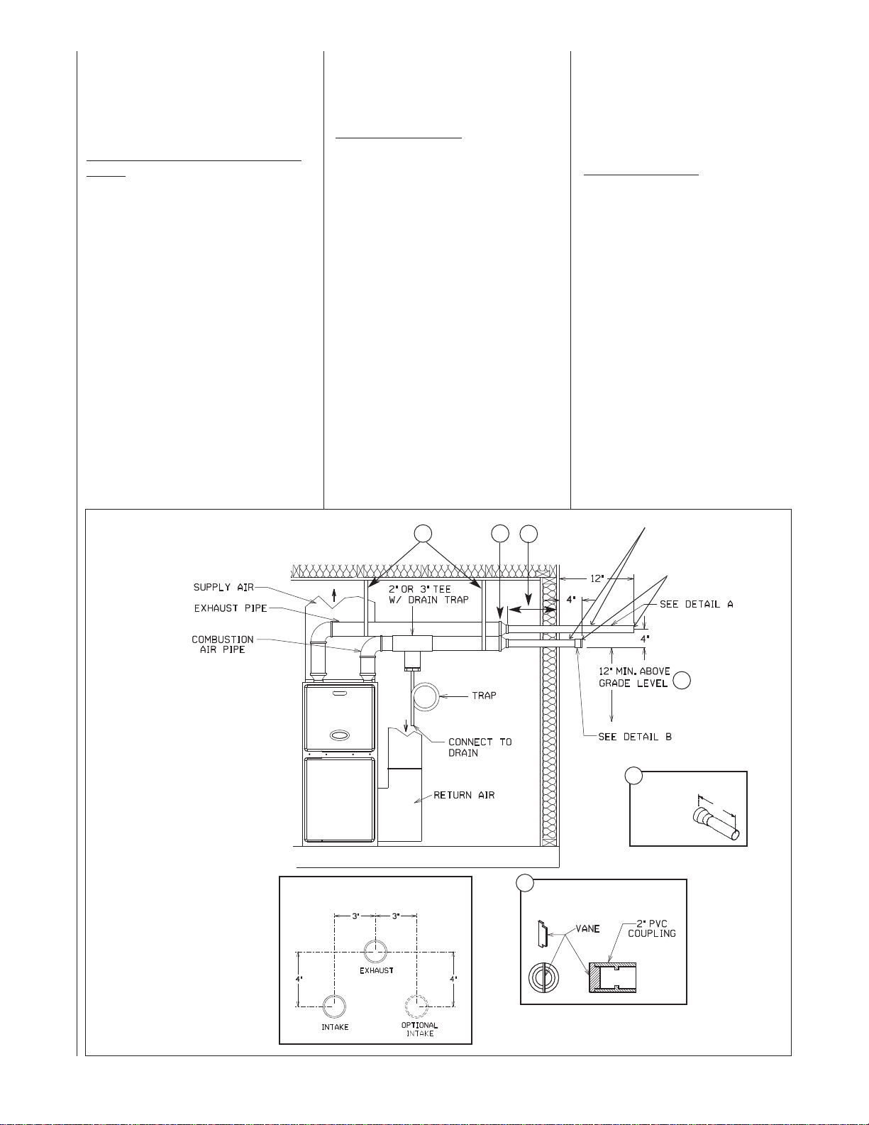
HORIZONTAL TERMINATIONS
All horizontal venting must be done
with direct venting (2 pipe). Furnaces
installed as non-direct vent must be
terminated vertically.
STANDARD HORIZONTAL TERMINA
TIONS
NOTE: A
intakes (except those using horizontal
concentric vent kit RXGY-E03A) must
have a drain tee assembly and trap
installed in the combustion air pipe as
close to the furnace as possible. This is
to drain any water that may enter the
combustion air pipe to prevent it from
entering the furnace vestibule area.
These parts are included in horizontal
vent kits RXGY-D02A, RXGY-D03Aand
RXGY-D04A.
NNOOTTEE::
t
above grade or anticipated snow levels.
Use alternate horizontal terminations
when termination locations are limited
and higher snow levels are anticipated.
((SSEEEE FFIIGGUURREE 1133))
ll furnaces with horizontal air
The combustion air and exhaust
erminations must be at least 12 inches
NNOOTTEE::
b
ustion air inlet with respect to the
sure the location of the com-
En
exhaust vent terminal complies with
Figure 13, detail C.
Combustion Air Piping
coupling with a wind deflector vane (pro-
vided) installed as follows:
: Use a 2" PVC
1. Install a 2" coupling to the combustion air pipe at the outside wall to
prevent the termination from being
pushed inward.
2. Cut a 2 1/4" length of 2" PVC pipe
and connect this to the coupling.
3. Connect another 2" coupling to the
end of the 2 1/4" length of pipe.
Terminate this outer coupling 4
inches from the wall.
4. Attach the vane in the final 2" coupling in the vertical position with
PVC cement.
IMPORTANT: To insure proper furnace operation, install the vane in
the vertical position as shown in
Figure 13, Detail B. Failure to install
the vane properly can result in nuisance tripping of the pressure
switch.
Exhaust Vent Piping
:
60,000 and 75,000 BTUH models:
Use 2" pipe only for the entire
length of the vent.
90,000 through 120,000 BTUH
models: Install a 2" coupling at the
outside wall to prevent the termination from being pushed inward. No
reduction of the 2" pipe used to
penetrate the wall is necessary.
Terminate the 2" PVC exhaust vent
at least 12 inches from the outside
wall.
FIGURE 13
STANDARD HORIZONTAL DIRECT VENTING
UPFLOW MODEL SHOWN
(TYPICAL FOR DOWNFLOW/HORIZONTAL MODELS)
NOTES:
SUPPORT HORIZONTAL
➀
PIPE EVERY FOUR FEET.
WHEN 3 IN. PIPE IS USED REDUCE TO
➁
2 IN. BEFORE PENETRATING OUTSIDE WALL.
18 IN. MAXIMUM. 2 IN. DIAMETER
➂
PIPE MAY BE USED INSIDE THE
WALL.
DETAIL “A” -
➃
TTEERRMMIINNAATTEE TTHHEE LLAASSTT 1122 IINNCCHHEESS
WWIITTHH 22” PPVVCC PPIIPPEE OONN 9900,,000000 AANNDD
112200,,000000 BBTTUUHH MMOODDEELLSS..
INCREASE THE 12 IN. MINIMUM
➄
ABOVE GRADE TO KEEP TERMINAL
OPENINGS ABOVE ANTICIPATED
LEVEL OF SNOW ACCUMULATION
WHERE APPLICABLE.
DETAIL “B”, INSTALL WIND DEFLEC-
➅
TOR VANE IN 2 IN. PVC COUPLING IN
VERTICAL POSITION USING PVC
SOLVENT.
THE COMBUSTION AIR TERMINATION
MUST BE IN THE SAME PRESSURE
ZONE AS THE EXHAUST TERMINATION.
EEXXHHAAUUSSTT TTEERRMMIINNAATTIIOONN
EXHAUST/INTAKE RELATIONSHIP
DETAIL C
PIPE REDUCTION NOT REQUIRED
1
2
3
ON 60 & 75K MODELS W/2” PIPE.
REDUCTION IS STILL REQUIRED
WITH 3” PIPE.
NO SCREENS OR ELBOWS
AT THE END OF THE PIPES
DETAIL C
5
4
DETAIL A
EXHAUST
TERMINATION
(3” PIPE ONLY)
6
COMBUSTION AIR TERMINATION
DETAIL B
12”
ST-A0407-00
22
Page 23

ALTERNATE HORIZONTAL TERMINATIONS (See Figure 14)
NNOOTTEE::
exhaust
The combustion air and
terminations must be at least
12 inches above grade or anticipated
snow levels. Alternate horizontal terminations allow the combustion air
and exhaust terminations to be raised
a maximum of 60 inches above the
wall penetrations to maintain the
required clearance.
NNOOTTEE::
extended
If combustion air vent pipe is
more than 24 inches, insulate the vent pipe between the two
outside 90° elbows with closed cell
insulation such as rubatex, armaflex
or equivalent.
NNOOTTEE::
combust
Ensure the location of the
ion air inlet with respect to
the exhaust vent terminal complies
with Figure 14.
Combustion Air Piping
: Use a 2" PVC
elbow with a wind deflector vane (provided) installed as follows:
1. Install a 2" elbow to the combustion
air pipe at the outside wall to prevent
the termination from being pushed
inward.
FIGURE 14
ALTERNATE HORIZONTAL DIRECT VENT TERMINATION
SEE DETAIL A
3" MAX.
NOTE: 3-1/2"
MAX. WHEN
D04 KIT IS
USED.
EXHAUST VENT
211/2" PVC FOR MODELS WITH 120,000 BTUH INPUT
(KIT NO. RXGY-D04A)
2" PVC FOR MODELS WITH INPUTS OF 90,000 THRU 120,000
BTUH. REDUCE TO 111/2" FOR MODELS WITH INPUTS OF 60,000
AND 75,000 BTUH. ELBOWS AND RISERS ARE 2" PVC.
12" FROM WALL
PIPE
SUPPORT
STRAP
DETAIL C
EXHAUST/INTAKE RELATIONSHIP
NOTE: If combustion air vent pipe is extended more
than 24 inches, insulate the vent pipes between the
two outside 90° elbows with closed cell insulation
such as rubatex, armaflex, or equivalent.
INTAKE VENT
211/2" PVC FOR MODELS WITH
120,000 BTUH INPUT.
2" PVC ELBOWS AND RISER
MODELS WITH INPUTS OF 75,000
THRU 120,000 BTUH.
USE KIT NO. RXGY-D02 OR D02A WHEN 2"
PIPE IS USED BETWEEN FURNACE AND
OUTSIDE WALL. USE KIT NO. RXGY-D03
OR D03A WHEN 3" PIPE IS USED.
DETAIL A
EXHAUST VENT FOR
MODELS WITH INPUT OF
60,000 AND 75,000 BTU
I339
2. Cut an adequate length of 2" PVC
pipe as needed to clear the anticipated snow level and connect this to
the elbow.
3. Connect another 2" elbow to the
end of the pipe such that the inlet is
facing away from the wall. This outer
coupling must terminate 4 inches
from the wall.
4. Attach the vane in the final 2" elbow
in the vertical position with PVC
solvent.
IMPORTANT: To insure proper furnace operation, the supplied vane
must be installed in the vertical position as shown in Figure 13, Detail B.
Exhaust Vent Piping
:
1. Install a 2" elbow to the exhaust vent
pipe at the outside wall to prevent the
termination from being pushed
inward.
2. Cut an adequate length of 2" PVC
pipe as needed to insure proper location of the exhaust vent termination
with respect to the combustion air
inlet and connect this to the elbow.
3. Connect another 2" elbow to the end
of the pipe such that the inlet is facing away from the wall.
Exhaust Vent Termination:
60,000 and 75,000 BTUH models:
Use 2" pipe only for the entire length
of the vent.
90,000 through 120,000 BTUH mod els: No reduction of the 2" pipe used
to penetrate the wall is necessary.
Terminate the 2" PVC exhaust vent
at least 12 inches from the outside
wall.
120,000 BTUH model with the
RXGY-D04A Horizontal Vent Kit:
Venting and terminations install the
same as above except the 2" pipe
and connectors are replaced with 2
1/2" pipe and connectors.
23
Page 24
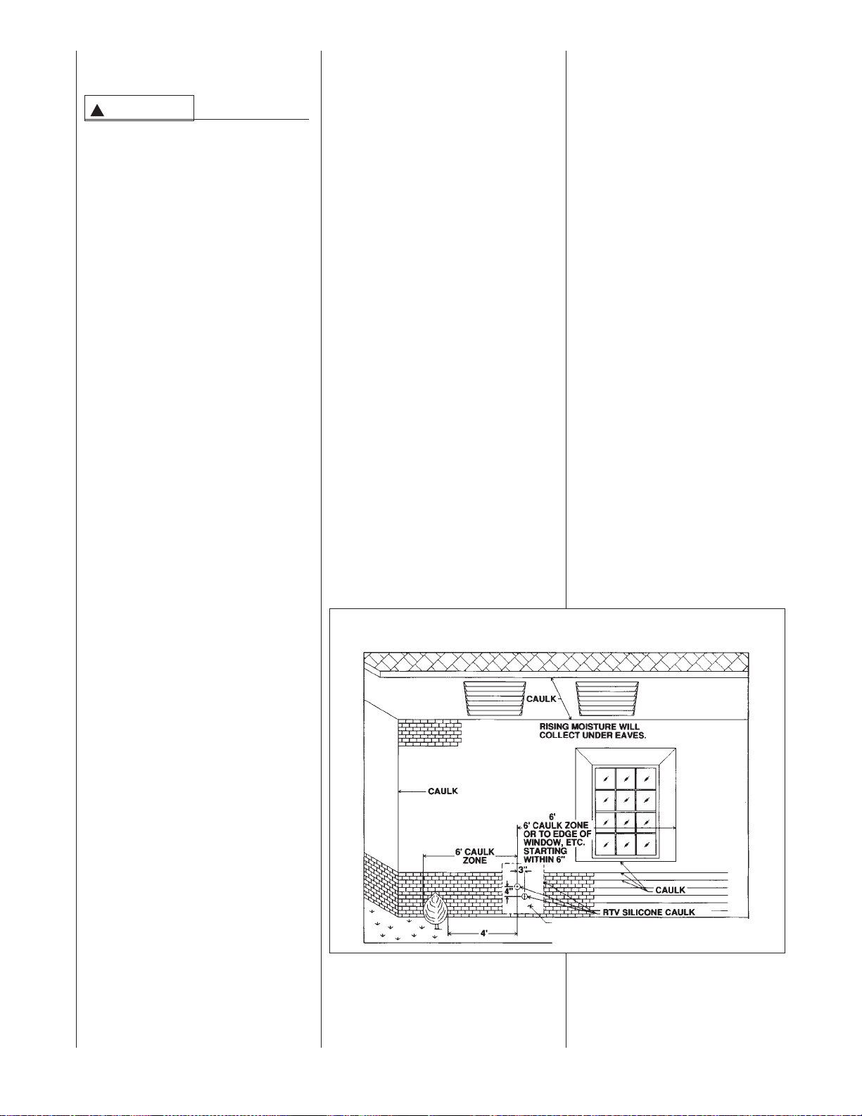
LOCATION REQUIREMENTS
HORIZONTAL DIRECT VENTS
CAUTION
!
THE COMBUSTION PRODUCTS
AND MOISTURE IN THE FLUE
GASES WILL CONDENSE AS
THEY LEAVE THE TERMINATION.
THE CONDENSATE CAN FREEZE
ON THE EXTERIOR WALL,
UNDER THE EAVES AND ON
SURROUNDING OBJECTS.
SOME DISCOLORATION TO THE
EXTERIOR OF THE BUILDING IS
TO BE EXPECTED. HOWEVER,
IMPROPER LOCATION OR
INSTALLATION CAN RESULT IN
STRUCTURAL OR EXTERIOR
FINISH DAMAGE TO THE BUILDING AND MAY RECIRCULATE
PRODUCTS OF COMBUSTION
INTO THE COMBUSTION AIR
TERMINAL AND FREEZE.
NOTE: In Canada vent terminations
must be in accordance with the current
CAN/CSA B149.1 Gas Installation
Code.
The vent must be installed with the following minimum clearances. See
Figures 15 and 16.
1. Locate the bottom of the vent terminal and the air inlet at least 12
inches above grade. Increase the
12-in. minimum to keep the terminal openings above the level of
snow accumulation, where applicable.
2. Do not terminate the vent over public walkways or over an area where
condensate or vapor could create a
nuisance or hazard.
3. Locate the vent terminal at least
one foot from any opening through
which flue gases could enter a
building.
4. Locate the vent terminal at least 3
feet above any forced air inlet
located within 10 feet, except the
combustion air inlet of a direct vent
appliance.
5. Allow the vent terminal minimum
horizontal clearance of 4 feet from
electric meters, gas meters, regulators and relief equipment.
6. Locate the furnace combustion air
inlet a sufficient distance from the
vent of any other gas or fuel burning appliance or electric clothes
dryer to prevent recirculation of the
flue gases into the furnace combustion air inlet. The only exception
to this requirement is the case of
multiventing two or more furnaces,
which is covered in the section on
multiventing in these instructions.
In addition to the minimum clearances
listed above, the vent location should
be governed by the following guidelines.
1. Do not terminate under any kind of
patio or deck (exceptions for
Canada are permitted under
CAN/CSA B149.1). If running the
vent under a deck, insulate it to
insure no condensate freezes and
blocks the pipe. The insulation
must be waterproof.
For vent considerations, the edge
of the deck must be considered
the outside wall.
2. Do not terminate behind any area
that may allow the flue products to
become stagnant and recirculate.
3. Do not locate on the side of a
building with prevailing winter
winds. This will help prevent moisture from freezing on walls and
overhangs (under eaves).
4. Do not extend vent directly
through brick or masonry surfaces. Use a rust-resistant sheet
metal or plastic backing plate
behind vent. See Figure 7.
5. Do not locate too close to shrubs
as condensate may stunt or
kill them.
FIGURE 15
MOISTURE ZONES
6. Minimum vertical clearances of 1
foot are recommended for overhangs up to 1 foot horizontal.
The vertical clearance should be
increased equally for each additional increase in horizontal overhang to a maximum vertical
clearance of 6 feet.
7. Caulk all cracks, seams and
joints within 6 feet horizontally
as well as 6 feet above and
below vent. See Figure 15.
8. Painted surfaces must be sound
and in good condition with no
cracking, peeling, etc. Painted
surfaces will require maintenance.
9. Do not expose 3" x 2" reducer/
bushing to outdoor ambient temperatures.
MULTIVENTING
IF VENTING TWO OR MORE FURNACES NEAR EACH OTHER IS
REQUIRED, EACH FURNACE
MUST BE INDIVIDUALLY VENTED –
NO COMMON VENTING IS PERMITTED. See Figures 17 and 18 for posi-
tioning of the terminations. When
2 FT. SQ. SHEET METAL PLATE ON BRICK OR
MASONRY SURFACE RECOMMENDED, BUT
NOT REQUIRED BY CODE.
24
Page 25
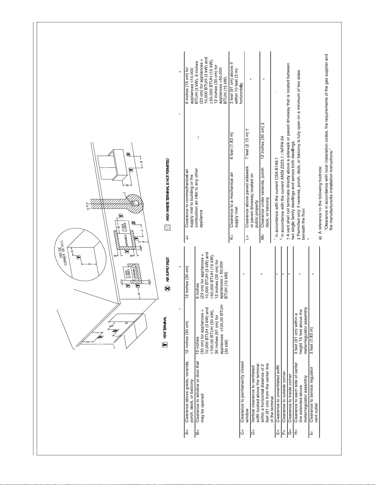
FIGURE 16
Natural Gas and Propane Installation Code
National Fuel Gas Code
Canadian Installations
US Installations
Canadian Installations
US Installations
1 ft. (30.5 cm)
4 ft. (1.22 m)
3 ft. (91 cm)
1 ft. (30.5 cm)
3 ft. (91 cm)
12 inches (30 cm) for
appliances > 10,000 BTUH
(3 kW) and < 100,000
BTUH (30 kW), 36 inches
(91 cm) for appliances >
100,000 BTUH (30 kW)
For clearances not specified in ANSI Z223.1 / NFPA 54 or CAN/CSA-B149, one of the following shall
be indicated:
DDIIRREECCTT VVEENNTT TTEERRMMIINNAALL CCLLEEAARRAANNCCEESS
25
Page 26
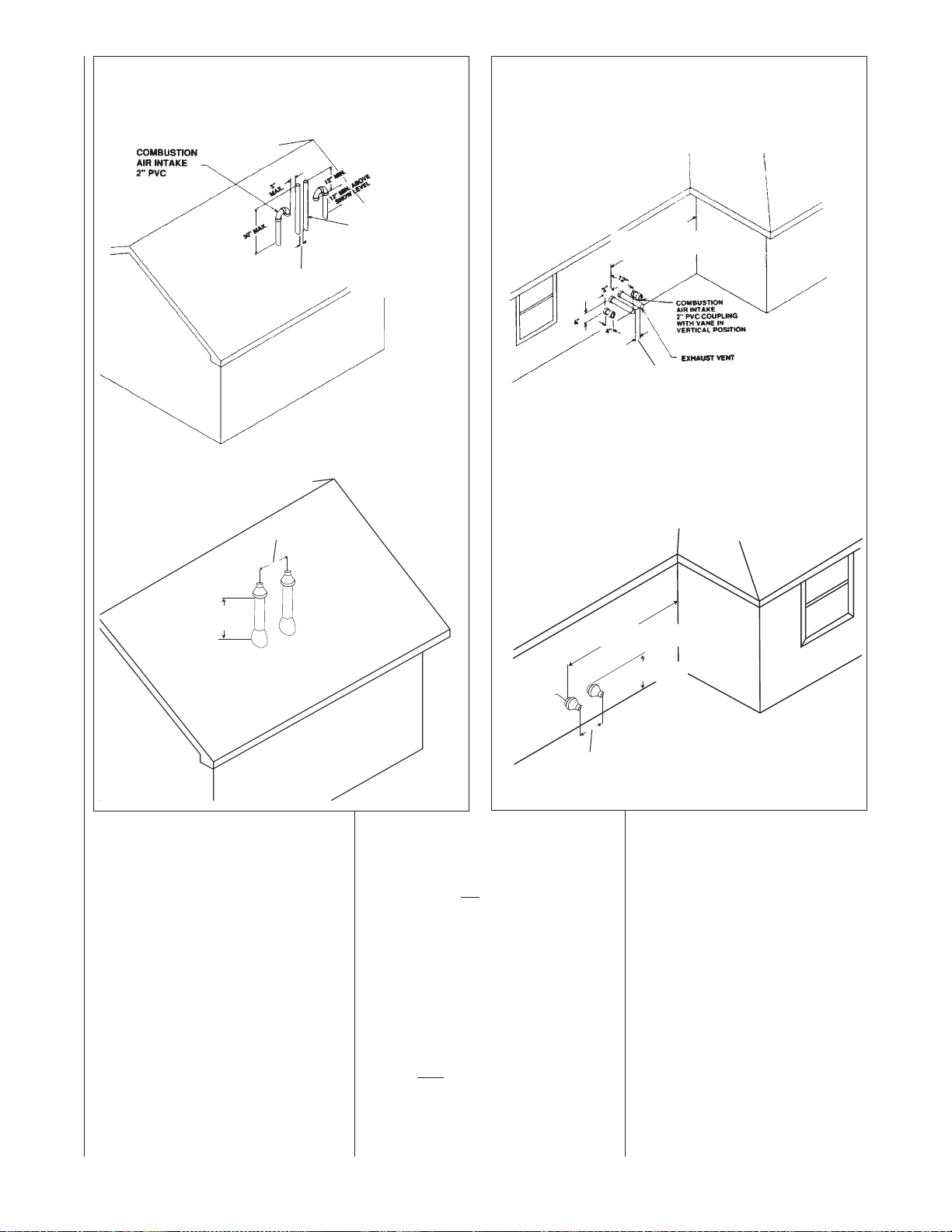
FIGURE 17
8"
MINIMUM 12" ABOVE AVERAGE
SNOW ACCUMULATION. MAXIMUM
OF 24 IN. ABOVE ROOF.
8"
MAXIMUM 1"
DISTANCE
FROM WALL
MINIMUM 12"
ABOVE GRADE
6' MINIMUM
10' RECOMMENDED
TWO FURNACE VENTING THROUGH ROOF
FIGURE 18
TWO FURNACE VENTING THROUGH WALL
TWO-PIPE VENTING
EEXXHHAAUUSSTT VVEENNTT
MMOODDEELLSS 0066--0077
NNOO VVEENNTT RREEDDUUCCTTIIOONN
RREEQQUUIIRREEDD..
MMOODDEELLSS 0099--1122 TTOO BBEE
33”” MMIINNIINNUUMM
2244”” MMAAXXIIMMUUMM
RREEDDUUCCEEDD FFRROOMM 33”” PPVVCC
TTOO 22”” PPVVCC BBEELLOOWW RROOOOFF
LLIINNEE..
CONCENTRIC VENTING
88”” MMIINNIINNUUMM
2244”” MMAAXXIIMMUUMM
TWO-PIPE VENTING
66‘‘ MMIINNIIMMUUMM,,
1100‘‘ RREECCOOMMMMEENNDDEEDD ((UUSS))
33‘‘ MMIINNIIMMUUMM CCAANNAADDAA OONNLLYY..
33”” MMIINNIINNUUMM
2244”” MMAAXXIIMMUUMM
CONCENTRIC VENTING
26
MMIINNIIMMUUMM 1122”” AABBOOVVEE AAVVEERRAAGGEE
SSNNOOWW AACCCCUUMMUULLAATTIIOONN MMAAXXIIMMUUMM
OOFF 2244 IINN.. AABBOOVVEE RROOOOFF..
IINN CCAANNAADDAA MMIINNIIMMUUMM 1188”” AABBOOVVEE
RROOOOFF LLIINNEE OORR MMAAXXIIMMUUMM 2244””
WWIITTHHOOUUTT AADDDDIITTIIOONNAALL SSUUPPPPOORRTT..
more than two furnaces are to be
vented, there must be at least 4 feet
between the first two furnaces and
the third, etc.
CONNECTING TO
FURNACE
IMPORTANT: Clean and deburr all
pipe cuts. The shavings must not be
allowed to block the exhaust, inlet or
condensate drain pipes.
IMPORTANT: When indoor combustion air is used, the inlet air opening
at the furnace must be protected from
accidental blockage. On downflow
models, install a double elbow in the
top inlet air opening.
SEE CONCENTRIC
VENT SECTION
ON PAGE 23
FOR MORE
INFORMATION.
UPFLOW MODELS
The exhaust air pipe connection is a
2-in. female PVC pipe fitting extending through the left
nace top plate. See Figure 19. This
opening has a protective cap which
should be removed just prior to
installing the exhaust pipe. When 2in. pipe is used, connect it directly to
this fitting. When 3-in. pipe is used,
connect a 2 to 3-in. coupling to this
fitting with a short piece of 2-in. PVC
pipe.
The inlet combustion air connection
is at the right
An alternate combustion inlet air connection may be made on the right
side of the jacket. The alternate con-
88”” MMIINNIINNUUMM
2244”” MMAAXXIIMMUUMM
side of the fur-
side of the top plate.
66‘‘ MMIINNIIMMUUMM,,
1100‘‘ RREECCOOMMMMEENNDDEEDD ((UUSS))
33‘‘ MMIINNIIMMUUMM CCAANNAADDAA OONNLLYY..
SEE CONCENTRIC VENT SECTION
ON PAGE 20 FOR MORE INFORMATION.
nection opening has a plastic cap. A
combustion inlet air connection fitting
is supplied with the furnace and it
must be installed in the furnace by
screwing it into the opening. Make
sure the rubber “O-ring” supplied with
the furnace is used with this fitting.
See Figure 19.
IMPORTANT: When using indoor
combustion air, the furnace air opening must be protected from accidental
blockage. Install a 2-inch 90° elbow
pointing downward on the side or a
double elbow pointing downward in
the top opening.
Page 27
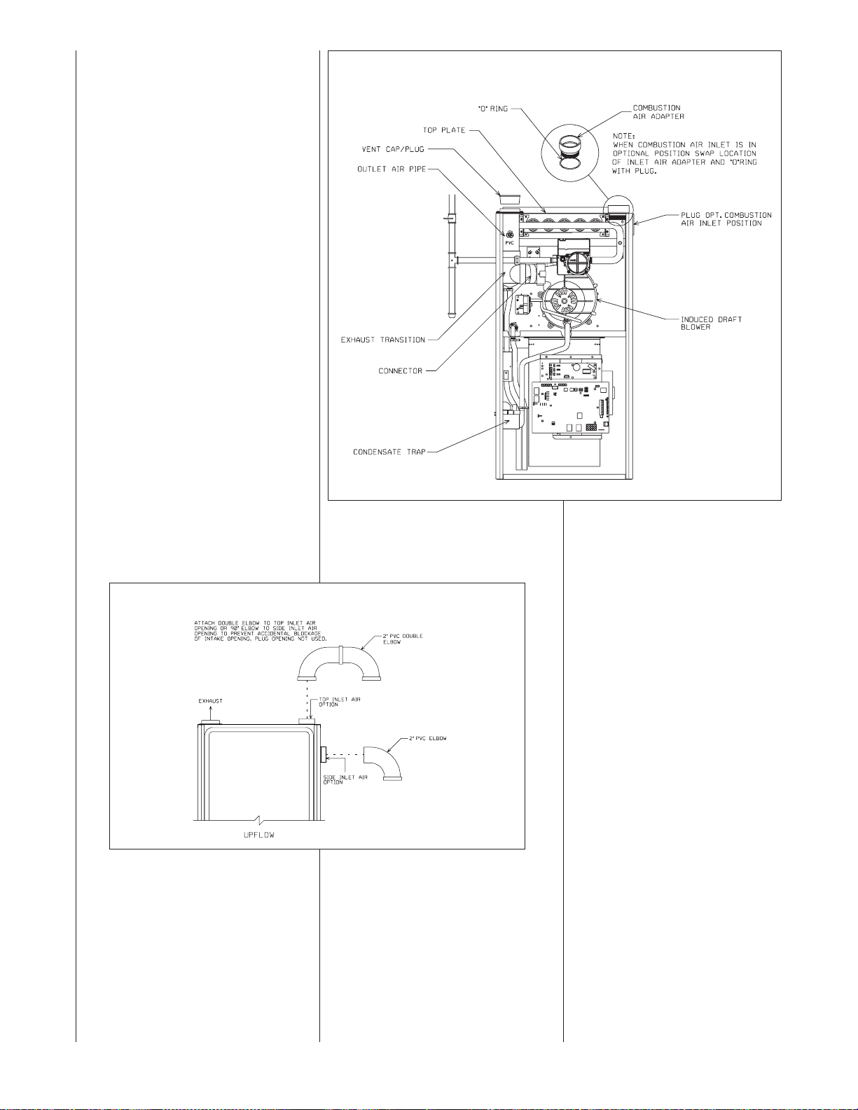
FIGURE 19
UPFLOW COMBUSTION AIR AND VENT PIPE CONNECTION
(GAS VALVE MAY BE DIFFERENT THAN SHOWN)
FIGURE 20
UPFLOW MODELS -- COMBUSTION AIR FITTING
ST-A1157-01
27
Page 28
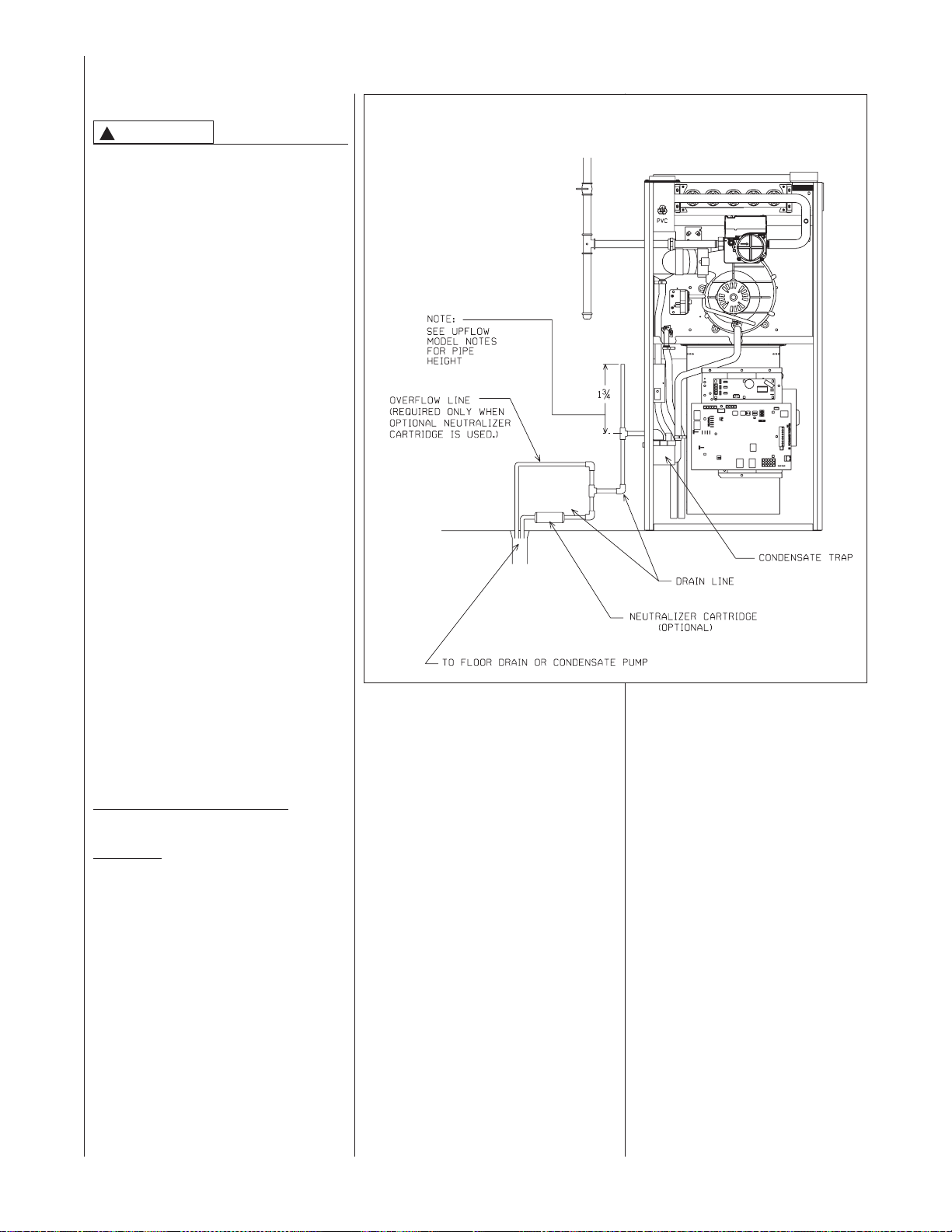
CONDENSATE DRAIN/OPTIONAL NEUTRALIZER
GENERAL INFORMATION
CAUTION
!
DO NOT RUN DRAIN OUTDOORS.
FREEZING OF CONDENSATE CAN
CAUSE PROPERTY DAMAGE.
IMPORTANT: Do not connect into a com-
mon drain line with an air conditioner
evaporator coil drain located below the
furnace. A blocked or restricted drain line
can result in overflow of the coil pan and
negate the furnace blocked-drain shutoff
control.
➤ IMPORTANT: If installing the unit over
a finished ceiling or living area, be certain
to install an auxiliary condensate drain
pan under the entire unit extending out
under the condensate tee. With the mini-
1
mum 5
or 13⁄4" for downflow models installed
above the tee, a blocked drain will result
in overflow from the riser. if the furnace is
installed in an attic, crawlspace or other
area where freezing temperatures may
occur, the furnace drain can freeze while
shut off for long periods of time.
If required by local codes, install a condensate neutralizer cartridge in the drain
line. Install cartridge in horizontal position
only. Also install an overflow line if routing
to a floor drain (see Figure 21). If available, install a condensate pump that is
resistant to acidic water. Pumps are available from your local distributor. If pump
used is not resistant to acidic water, a
condensate neutralizer must be used
ahead of the pump. The condensate
pump must have an auxiliary safety
switch to prevent operation of the furnace
and resulting overflow of condensate in
the event of pump failure. The safety
switch must be wired through the “R” circuit only (low voltage) to provide operation
in either heating or cooling modes.
When selecting neutralizer cartridges and
condensate pumps, use the following
data:
CONDENSATE PRODUCTION:
MAX (ALL MODELS) = 1-2 gallons per hr.
⁄2" riser for upflow models
FIGURE 21
UPFLOW CONDENSATE DRAIN
(GAS VALVE MAY BE DIFFERENT THAN SHOWN)
ST-A1158-01
pH LEVEL:
3.2 - 4.5 using OUTDOOR air
2.2 - 4.5 using INDOOR air
(neutral pH = 7.0)
UPFLOW MODELS
The condensate drain trap is located in
the blower compartment on the left- hand
side of the jacket. A short piece of 1⁄2-in.
PVC pipe and a 1⁄2-in. tee are provided.
Connect the 1⁄2-in. pipe to the elbow on
the trap and the tee to this pipe so that
the open end is upward. Run a drain tube
from the bottom of the tee to a floor drain
or condensate pump.
IMPORTANT: If installing the unit over a
finished ceiling or living area, be certain
to install an auxiliary condensate drain
pan under the entire unit extending out
under the condensate tee.
28
Page 29
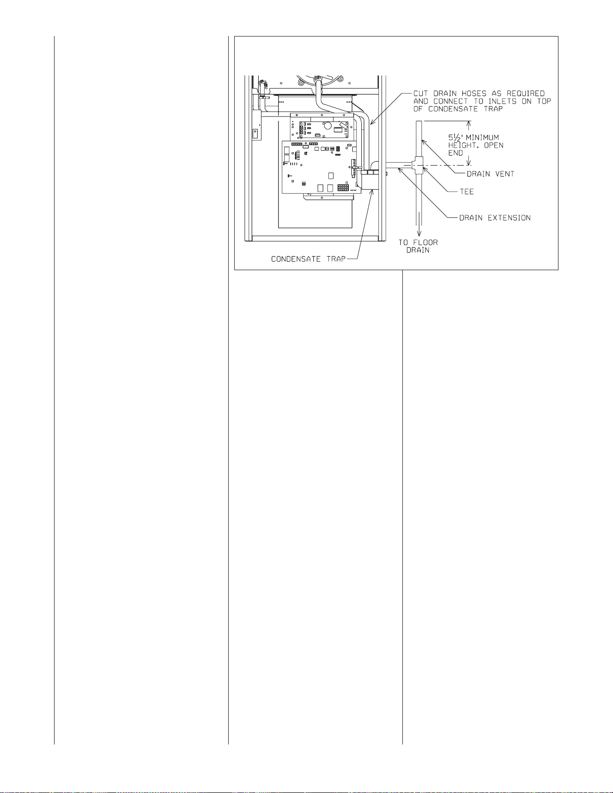
IMPORTANT: There are two options
when choosing a height for the condensate riser:
CONDENSATE OVERFLOW: With a
1
5
⁄2inch riser installed above the tee,
a blocked drain will result in overflow
from the riser.
FURNACE SHUTDOWN: To cause
the furnace to shut down when a
blocked drain is present, install a riser
which is a minimum of 10
13
⁄16”. If the
furnace is installed in an attic, crawlspace or other area where freezing
temperatures may occur, the furnace
drain can freeze while shut off for long
periods of time.
Use a solvent cement that is compatible with PVC material. Cut the drain
hoses to the appropriate length and
connect to the trap with hose clamps.
Tighten the clamps with pliers and
check for leaks after attaching.
FIGURE 22
UPFLOW OPPOSITE SIDE CONDENSATE TRAP CONNECTION
(NO KIT REQUIRED)
REVERSING THE TRAP
UPFLOW MODELS
The trap may be moved to the right
side for right-side drainage. Open the
knockout for the drain on the right side
of the cabinet. Remove the bracket
holding the trap from the left side.
Seal the left side drain hole with a
plug provided in the cloth bag with the
furnace. Position the mounting bracket
and trap so that the drain elbow is
centered in the hole on the right. See
Figure 22.
Drill two holes in the cabinet to mount
the bracket. Mount the trap and bracket to the right side with the drain
elbow pointing through the knockout.
Connect the
above. Route the drain hoses behind
the top of the electric box, cut to the
appropriate length, and connect to the
trap with hose clamps.
IMPORTANT: Do not connect into a
common drain line with an air conditioner evaporator coil drain located
above the furnace. A blocked or
restricted drain line can result in overflow of the coil pan and negate the
furnace blocked drain shutoff control.
1
⁄2" pipe and tee as noted
ST-A1159-01
29
Page 30
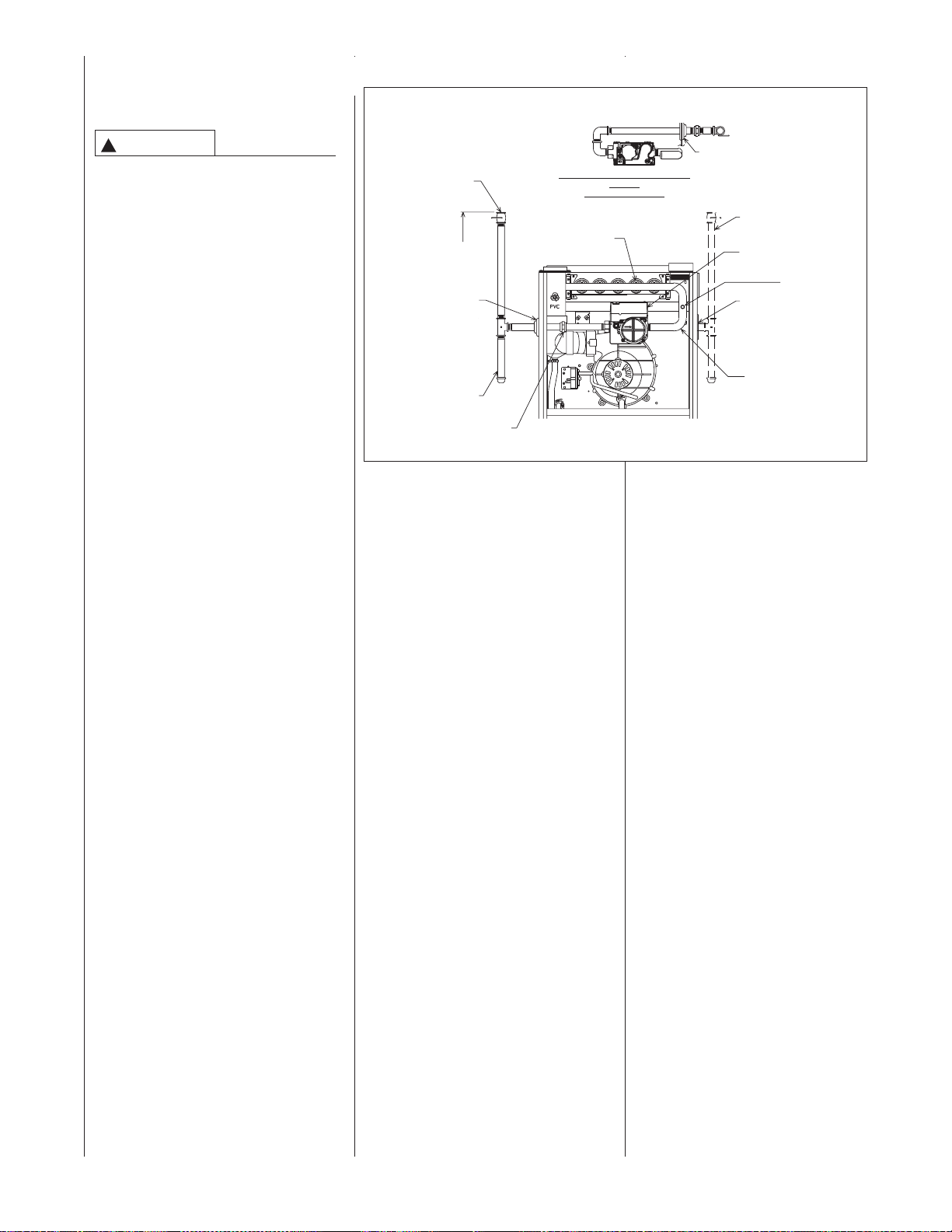
GAS SUPPLY AND PIPING
GAS SUPPLY
WARNING
!
THIS FURNACE IS EQUIPPED
AT THE FACTORY FOR USE ON
NATURAL GAS ONLY. CONVERSION TO LP GAS REQUIRES A
SPECIAL KIT
TTHHEE DDIISSTTRRIIBBUUTTOORR
USE THE PROPER CONVERSION KIT CAN CAUSE FIRE,
CARBON MONOXIDE POISONING, EXPLOSION, PROPERTY
DAMAGE, PERSONAL INJURY
OR DEATH.
See the conversion kit index supplied with the furnace. This index
identifies the proper LP Gas
Conversion Kit required for each
particular furnace.
IMPORTANT: Any additions, changes
or conversions required for the furnace
to satisfactorily meet the application
should be made by a qualified installer,
service agency or the gas supplier,
using factory-specified or approved
parts.
IMPORTANT: Connect this furnace
only to gas supplied by a commercial
utility.
IMPORTANT: A U.L. recognized
fuel gas and CO detector(s) are recommended in all applications, and their
installation should be in accordance
with the manufacturer’s recommendations and/or local laws, rules, regulations or customs.
AAVVAAIILLAABBLLEE FFRROOMM
. FAILURE TO
FIGURE 23
GAS PIPING -- UPFLOW INSTALLATION
(GAS VALVE MAY BE DIFFERENT
THAN SHOWN)
MANUAL
GAS VALVE
4 TO 5 FT.
ABOVE FLOOR
REQ’D BY
SOME
UTILITIES.
GROMMET
(IN NORMAL
POSITION)
DRIP LEG
UNION
(TYPICAL INSTALLATION)
TTOOPP VVIIEEWW OOFF GGAASS LLIINNEE AANNDD
VVAALLVVEE
IINN OOPPTT.. PPOOSSIITTIIOONN
BURNERS
GROMMET
NOTE:
WHEN GAS LINE IS IN OPT.
POSITION, SWAP LOCATION
OF GROMMET AND PLUG.
OPTIONAL GAS LINE
POSITION
GAS VALVE
PLUG
(IN NORMAL
POSITION)
MANIFOLD
IMPORTANT: Do not run a flexible gas connector inside the unit.
MANIFOLD
PRESSURE TAP
A1122-01_1
GAS PIPING
Install the gas piping according to all
local codes and regulations of the utility company.
If possible, run a separate gas supply
line directly from the meter to the furnace. Consult the local gas company
for the location of the manual main
shut-off valve. The gas line and man-
ual gas valve must be adequate in
size to prevent undue pressure drop
and never smaller than the pipe size
30
Page 31

to the combination gas valve on the
furnace. Refer to Table 9 for the recom-
mended gas pipe size for natural gas
and Table 10 for L.P. See Figure 23 for
typical gas pipe connections.
Install a ground joint union between
the manual gas stop and the main
gas valve to easily remove the control valve assembly. Install a manual
gas stop in the gas line outside the
furnace cabinet. The gas stop should
be readily accessible to turn the gas
supply on or off. Install a drip leg in the
gas supply line as close to the furnace
as possible. Always use a pipe compound resistant to the action of liquefied
petroleum gases on all threaded connections.
IMPORTANT: When making gas pipe
connections, use a back-up wrench to
prevent any twisting of the control
assembly and gas valve.
Any strains on the gas valve can
change the position of the gas orifices in
the burners. This can cause erratic furnace operation.
IMPORTANT: Do not run a flexible gas
connector inside the unit. If local codes
allow the use of a flexible gas appliance
connector, always use a new listed connector. Do not use a connector which
has previously serviced another gas
appliance. Massachusetts law requires
that all flexible gas connectors be less
than 36”.
The gas pipe grommet in the cabinet
does not seal around a flexible gas connector. It is important to have all
openings in the cabinet burner compartment sealed for proper furnace
operation.
IMPORTANT: To insure a good seal, the
gas pipe that runs through the grommet
must be 1/2” schedule 40 black pipe.
IMPORTANT: Ensure that the furnace
gas control valve is not subjected to
high gas line supply pressures (13.5”
w.c. or above).
DISCONNECT the furnace and its individual shut-off valve from the gas supply
piping during any pressure testing that
exceeds 1/2 PSIG (3.23 kPa or 13"
w.c.).
GAS PRESSURE
Natural gas supply pressure should
be 5" to 10.5" w.c. LP gas supply
pressure should be 11" to 13" w.c.
This pressure must be maintained
with all other gas-fired appliances in
operation.
WARNING
!
NEVER PURGE A GAS LINE INTO
THE COMBUSTION CHAMBER.
NEVER USE MATCHES, FLAME
OR ANY IGNITION SOURCE FOR
CHECKING LEAKAGE. FAILURE
TO ADHERE TO THIS WARNING
CAN CAUSE A FIRE OR EXPLOSION RESULTING IN PROPERTY
DAMAGE, PERSONAL INJURY
OR DEATH.
To check for gas leakage, use an
approved chloride-free soap and water
solution, an electronic combustible gas
detector, or other approved method.
GAS VALVE
This furnace has a 24-volt operated
main solenoid valve. It has ports for
measuring supply pressure and manifold
pressure. A manual control is on the
valve body. It can be set to only the
“ON” or “OFF” positions.
See Figure 24.
FIGURE 24
GAS VALVE
STEPPER CONTROL-FUEL CODE HA
OR HB
ON/OFF
SWITCH
31
Page 32

TABLE 9
NATURAL GAS PIPE CAPACITY TABLE (CU. FT./HR.)
Capacity of gas pipe of different diameters and lengths in cu. ft. per hr. with pressure drop of 0.3 in. and
specific gravity of 0.60 (natural gas).
Nominal Length of Pipe, Feet
Iron Pipe
Size, Inches 10 20 30 40 50 60 70 80
1/2 132 92 73 63 56 50 46 43
3/4 278 190 152 130 115 105 96 90
1 520 350 285 245 215 195 180 170
1-1/4 1,050 730 590 500 440 400 370 350
1-1/2 1,600 1,100 890 760 670 610 560 530
After the length of pipe has been determined, select the pipe size which will provide the minimum cubic
feet per hour required for the gas input rating of the furnace. By formula:
Cu. Ft. Per Hr. Required =
The gas input of the furnace is marked on the furnace rating plate. The heating value of the gas
(BTU/FT3) may be determined by consulting the local natural gas utility or the LP gas supplier.
Gas Input of Furnace (BTU/HR)
Heating Value of Gas (BTU/FT
3
)
TABLE 10
LP GAS PIPE CAPACITY TABLE (CU. FT./HR.)
Maximum capacity of pipe in thousands of BTU per hour of undiluted liquefied petroleum gases (at 11
inches water column inlet pressure).
(Based on a Pressure Drop of 0.5 Inch Water Column)
Nominal Length of Pipe, Feet
Iron Pipe
Size, Inches 10 20 30 40 50 60 70 80 90 100 125 150
1/2 275 189 152 129 114 103 96 89 83 78 69 63
3/4 567 393 315 267 237 217 196 182 173 162 146 132
1 1,071 732 590 504 448 409 378 346 322 307 275 252
1-1/4 2,205 1,496 1,212 1,039 913 834 771 724 677 630 567 511
1-1/2 3,307 2,299 1,858 1,559 1,417 1,275 1,181 1,086 1,023 976 866 787
2 6,221 4,331 3,465 2,992 2,646 2,394 2,205 2,047 1,921 1,811 1,606 1,496
Example (LP): Input BTU requirement of unit, 150,000
Equivalent length of pipe, 60 ft. = 3/4" IPS required.
LP COPPER TUBE SIZING TABLE
Sizing between single or second stage (low pressure) regulator and appliance. Maximum capacity of pipe in thousands of BTU
per hour of undiluted propane gases (at 11" w.c. setting).
Outside Diameter
Copper Tubing,
Type L 10 20 30 40 50 60 80 100 125 150
3/8" 49 34 27 23 20 19 16 14 11 10
1/2" 110 76 61 52 46 42 36 32 28 26
5/8" 206 141 114 97 86 78 67 59 52 48
3/4" 348 239 192 164 146 132 113 100 89 80
7/8" 536 368 296 253 224 203 174 154 137 124
Length of Pipe, Feet
32
Page 33

LP CONVERSION
IMPORTANT: LP gas from trucks used
to transport liquid-based fertilizers can
contain chemicals that will damage the
furnace. Verify that your gas supplier
does not use the same truck to transport materials other than LP.
This furnace is shipped from the factory for use on natural gas only. For use
on LP gas, a proper conversion is
required.
Conversion of the furnace for use with
LP gas requires conversion kit RXGJ-
FP27. (Gas valve not required.)
!
CAUTION
ELEVATIONS ABOVE 2000 FT
REQUIRE THAT THE FURNACE
INPUT RATING BE ADJUSTED AND
THAT THE SIZE OF THE BURNER
ORIFICES BE RE-CALCULATED
BASED ON ELEVATION AND GAS
HEATING VALUE. THE BURNER ORIFICES MAY (OR MAY NOT) NEED TO
BE CHANGED. SEE THE SECTION
TITLED “HIGH ALTITUDE INSTALLATIONS” OF THIS BOOK FOR
INSTRUCTIONS.
High altitude installations above 5,000
feet are not permitted with RGFG furnace models.
NOTE: Order the correct LP conversion kit available from the local distributor. Furnace conversion to LP gas
must be performed by a qualified
installer, service agency, or the gas
supplier.
To change orifice spuds for conversion
to LP:
1. Shut off the manual gas valve and
disconnect the gas line at the
union ahead of the unit gas valve.
2. Remove the gas valve and manifold assembly.
3. Replace the orifice spuds.
4. For servo (stepper) controlled gas
valve (fuel code HA or HB): Install
the jumper supplied with the kit
into the valve as shown in Figures
25 and 27. Make sure
jumper connects the two pins and
verify by checking manifold pressure at high fire. It should be
approx. 10” w.c.
5. Re-attach the manifold assembly
to the unit and connect the gas
line to the gas valve.
6. Place the conversion label, included in the kit, adjacent to the CSA
rating plate. Also for servo controlled gas valves only (fuel code
HA or HB) be sure to install the
label titled “LP” over the hole
where the jumper is inserted in
Item 4 above.
that the
7. Check unit for leaks.
8. Follow lighting instructions to put
the furnace into operation.
9. Check manifold pressure.
Consult Tables 13 (U.S.) and 14
(Canada), if there is any question concerning orifice sizing.
NOTE: LP orifices are included in the kit
but they may need to be exchanged
based on heating value and/or elevation. LP orifices must be selected based
on the altitude of the installation. See
orifice chart.
NOTE ABOUT LP CONVERSION
OF STEPPER-CONTROLLED
MODULATING GAS VALVE: To
convert the stepper-controlled modulating gas valve, a jumper is
required to connect the two pins
inside the jumper well. It is possible
to install the jumper such that the
pins are not connected. This is
incorrect. The jumper must connect
the pins together inside the jumper
well. This can be confirmed by visual inspection and by verifying proper
manifold pressure at high fire
(100%) after the jumper is installed.
Manifold pressure should always be
checked by the installer when converting the furnace for LP operation.
Figures 26 and 27 below show the
incorrect way and the correct way
to install the jumper. The jumper
well is located next to the adjustment well (with “+” and “–” text and
two-headed arrow) and will be covered by a sticker or label. To convert to LP the label over the jumper
well will need to be removed.
FIGURE 25
SERVO CONTROLLED GAS VALVE SUPPLY PRESSURE TAP AND LP JUMPER WELL
LP JUMPER WELL
NOTE: REMOVE COVER TO
ADJUSTMENT WELL WHEN MAKING ADJUSTMENTS. REPLACE
WHEN DONE.
NOTE: THE ADJUSTMENT WHEEL
WILL NOT STOP ROTATING
WHEN IT HITS THE MAXIMUM OR
MINIMUM POSITION. INSTEAD IT
WILL CONTINUE TO ROTATE TO
THE OPPOSITE ADJUSTMENT.
USE THE LETTERS ON THE
WHEEL AS A GUIDE.
(INSERT JUMPER HERE)
SUPPLY PRESSURE TAP
ADJUSTMENT WELL
33
Page 34

FIGURE 26
LP JUMPER INSTALLED ON SERVO MODULATING GAS VALVE WITH PINS NOT CONNECTED. THIS IS
SURE THAT THE JUMPER CONNECTS THE
TWO PINS TOGETHER AND VERIFY MANIFOLD GAS PRESSURE AT HIGH FIRE TO
MAKE SURE THE VALVE IS PROPERLY
CONVERTED FOR LP GAS
IINNCCOORRRREECCTT
. MAKE
FICES MAY (OR MAY NOT) NEED TO
BE CHANGED. SEE THE SECTION
TITLED “HIGH ALTITUDE INSTALLATIONS” OF THIS BOOK FOR
INSTRUCTIONS.
Supply Gas Pressure Measure-ment.
1. With gas shut off to the furnace
at the manual gas valve outside
JUMPER
IIMMPPRROOPPEERRLLYY
INSTALLED.
NOTE THAT
PINS ARE
NOT CONNECTED.
the unit, remove the line
pressure tap plug on the gas
valve. See Figure 25.
2. Connect a U-Tube manometer to
the pressure tap.
3. Turn on the gas supply and operate
INCORRECT
FIGURE 27
LP JUMPER INSTALLED ON SERVO MODULATING GAS VALVE WITH PINS PROPERLY
CONNECTED. THIS IS
SURE THAT THE JUMPER CONNECTS THE
TWO PINS TOGETHER AND VERIFY MANIFOLD GAS PRESSURE AT HIGH FIRE TO
MAKE SURE THAT THE VALVE IS PROPERLY CONVERTED FOR LP GAS
CCOORRRREECCTT
JUMPER
PPRROOPPEERRLLYY
INSTALLED.
NOTE THAT
PINS ARE
CONNECTED.
. MAKE
the furnace at 100% and all other
gas-fired units on the same gas line
as the furnace.
4. Note or adjust the supply-line pressure to give:
A. 5" - 10.5" w.c. for natural gas.
B. 11" - 13" w.c. for LP gas.
5. Shut off the gas at the manual gas
valve and remove the
U-Tube manometer.
6. Replace the supply-line pressure
tap plug before turning on the gas.
7. Check unit for leaks.
If the supply-line pressure is above
these ranges, install an in-line gas regu-
CORRECT
lator to the furnace for natural gas units.
With LP gas, have the LP supplier
SETTING GAS PRESSURE
A properly calibrated pressure gauge
or U-Tube manometer is required for
accurate gas pressure measurements.
!
CAUTION
ELEVATIONS ABOVE 2000 FT
REQUIRE THAT THE FURNACE
reduce the supply-line pressure at the
regulator.
If supply-line pressure is below these
ranges, either remove any restrictions in
the gas supply piping or enlarge the gas
pipe. See Tables 9 and 10. With LP gas,
have the LP supplier adjust the supplyline pressure at the regulator.
INPUT RATING BE ADJUSTED AND
THAT THE SIZE OF THE BURNER
ORIFICES BE RE-CALCULATED
BASED ON ELEVATION AND GAS
HEATING VALUE. THE BURNER ORI-
FIGURE 28
SERVO-CONTROLLED GAS VALVE MANIFOLD PRESSURE TAP LOCATION
MANIFOLD TAP
!
CAUTION
ELEVATIONS ABOVE 2000 FT
REQUIRE THAT THE FURNACE
INPUT RATING BE ADJUSTED
AND THAT THE SIZE OF THE
BURNER ORIFICES BE RE-CALCULATED BASED ON ELEVATION
AND GAS HEATING VALUE. THE
BURNER ORIFICES MAY (OR MAY
NOT) NEED TO BE CHANGED. SEE
THE SECTION TITLED “HIGH ALTITUDE INSTALLATIONS” OF THIS
BOOK FOR INSTRUCTIONS.
➤ SERVO GAS VALVE (FUEL
‰ CODE: HA OR HB) MANIFOLD
‰ GAS PRESSURE
‰ MEASUREMENT/ADJUSTMENT.
1. With the gas to the unit shut off
at the manual gas valve, remove
the outlet pressure tap plug in
the gas valve. See Figure 28.
2. Connect the positive pressure
hose from a manometer to the
pressure tap.
3. Note the manifold gas pressure
to be:
A. 3.5" w.c. (±.3) for natural gas .
B. 10.0" w.c. ( ±.5) for LP gas.
NOTE: Make sure the unit is
operating at maximum heating
capacity (100%) before adjusting
the manifold pressure.
4. To adjust the pressure regulator,
insert a small slotted screwdriver
into the opening at the top of the
valve.
NOTE: Only small variations in
gas pressure should be made by
adjusting the pressure regulator.
NOTE:Allow up to 5 seconds for
each change in manifold pressure.
5. Turn the adjustment screw clockwise to increase pressure, or
counterclockwise to decrease
pressure.
6. Check manifold gas pressure.
7. Repeat step 5 & 6 if needed.
8. Securely replace the regulator
cap.
NOTE: Shut off gas at the manual gas valve and remove the UTube manometer.
9. Replace the manifold pressure
tap plug before turning on
the gas.
10. Check unit for leaks.
NOTE: Do not use gas valve pres-
sure adjustment as a means to
adjust temperature rise. The blower
motor will change speed to maintain
a reasonably constant temperature
rise.
34
Page 35

ELECTRICAL WIRING
WARNING
!
TURN OFF ELECTRIC POWER AT
FUSE BOX OR SERVICE PANEL
BEFORE MAKING ANY ELECTRICAL CONNECTIONS. FAILURE TO
DO SO CAN CAUSE ELECTRICAL
SHOCK RESULTING IN PERSONAL INJURY OR DEATH.
WARNING
!
THE CABINET MUST HAVE AN
UNINTERRUPTED GROUND
ACCORDING TO THE LATEST
EDITION OF THE NATIONAL
ELECTRICAL CODE, ANSI/
NFPA70-, OR IN CANADA, THE
CANADIAN ELECTRICAL CODE,
CSA-C22.1 OR LOCAL CODES
THAT APPLY. A GROUND SCREW
IS PROVIDED IN THE JUNCTION
BOX. FAILURE TO PROPERLY
CONNECT THE GROUND WIRE
CAN CAUSE ELECTRICAL
SHOCK RESULTING IN PERSONAL INJURY OR DEATH.
ate wiring diagram located on the inside
cover of the furnace control box and in
these instructions.
NOTE: The electrical junction box may
be moved to the right side if necessary. A
knockout is provided. Seal the opposite
hole with plug provided.
WARNING
!
L1 TERMINAL AND NEUTRAL TERMINAL POLARITY MUST BE OBSERVED
WHEN MAKING FIELD CONNECTIONS
TO THE FURNACE. FAILURE TO DO
SO WILL EXPOSE LIVE WIRING IN
THE BLOWER COMPARTMENT WHEN
THE DOOR IS REMOVED. TOUCHING
THESE LIVE CIRCUITS COULD
RESULT IN PERMANENT INJURY OR
DEATH FROM ELECTRICAL SHOCK.
FIGURE 29
JUNCTION BOX LOCATION
Make all electrical connections in
accordance with the latest edition of
the National Electrical Code
ANSI/NFPA70 – or in Canada, the
Canadian Electrical Code Part 1CSA Standard C22.1 and local codes
having jurisdiction.
These may be obtained from:
National Fire Protection
Association, Inc.
Batterymarch Park
Quincy, MA 02269
Canadian Standards Association
178 Rexdale Boulevard
Rexdale, Ontario, Canada M9W 1R3
WARNING
!
THIS FURNACE IS EQUIPPED
WITH A BLOWER DOOR SAFETY
SWITCH. DO NOT DISABLE THIS
SWITCH. FAILURE TO FOLLOW
THIS WARNING CAN RESULT IN
ELECTRICAL SHOCK, PERSONAL INJURY OR DEATH.
IMPORTANT: The furnace must be
installed so that the electrical components are protected from water.
A grounding wire is provided to connect
to the incoming grounding wire from
line power. The furnace must be permanently grounded in accordance with all
national and local codes.
Before proceeding with the electrical
connections, be certain that the service
panel voltage, frequency and phase corresponds to that specified on the furnace rating plate. Maximum over-current
protection is 15 amperes.
Use a separate, fused branch electrical
circuit containing a properly sized fuse or
circuit breaker. Connect this circuit directly
from the main switch box to an electrical
disconnect that is readily accessible and
located within arm’s reach (2 ft.) of the
furnace. Connect from the electrical disconnect to the junction box on the left
side of the furnace, inside the blower
compartment. See Figure 29. For the
proper connection, refer to the appropri-
UPFLOW
MODELS
35
Page 36

ELECTRICAL CHECKS
Line Power Check
The furnace must have a nominal 115
volt power supply for proper operation.
If there is not a consistent power supply, contact a licensed electrician to
correct the problem.
1. With the blower compartment door
off, manually hold the push button
door switch in.
2. Call for heat at the thermostat.
3. With the unit operating, use a voltmeter to measure the voltage from
any 120 VAC terminal to any neutral connection.
4. The voltage should be a nominal
115 volts (acceptable 105-120VAC).
This test should be made with the unit
in full operation.
Polarity Check
If line & neutral are reversed, a fault
code (26) will be displayed at the furnace seven segment display (SSD)
and at the communicating thermostat
active fault display screen (communicating systems only).
Proper line voltage polarity, or phasing,
is a must for this furnace to operate.
Use a volt meter to make this check.
1. With the blower compartment door
off, manually hold the push button
door switch in.
2. Use a voltmeter to measure the
voltage from any 120 VAC terminal
to any bare metal ground on the
furnace.
3. The voltage should be a nominal
115 volts (acceptable 105-120VAC).
4. Use a voltmeter to measure the
voltage from any neutral terminal to
the bare metal ground on the furnace.
5. The voltage should be less than 1.0
VAC.
6. If the voltage from any 120 VAC terminal to ground is less than 1.0
VAC volts and the voltage from a
neutral to ground is a nominal 115
volts, the polarity is reversed.
7. To correct the problem, either
reverse the hot and neutral wires to
the furnace or have a licensed electrician check the building wiring.
Control Voltage Check
1. With the blower compartment door
off, manually hold the push button
door switch in.
2. Call for heat at the thermostat.
(Does not include communicating
thermostats.)
3. With the unit operating, use a voltmeter to measure the voltage from
control voltage terminal “W” to terminal “C” on the furnace control
board.
4. The voltage should be a nominal 24
volts (Acceptable 18-30 VAC).
This test should be made with the unit
in full operation.
36
Page 37

ACCESSORIES
FIELD-INSTALLED
OPTION ACCESSORIES
TWINNING: Twinning is NOT permitted
on any modulating furnace model.
ELECTRONIC AIR CLEANER
NOTE: There is a 30 second lag time for
energizing the Electronic Air Cleaner.
E.A.C. will not energize until 30 seconds
after the Indoor Blower Motor (IBM).
Line voltage power is supplied from the
terminal “EAC”, see Figure 30, and a
neutral terminal on the control board.
This will power the electronic air cleaner
whenever the blower is operating and
delivering the recommended minimum
CFM. The 60 and 75 KBTU models,
which are capable of a maximum delivery of 1200 CFM, will operate the electronic air cleaner at 500 CFM and
above. The 90, 105 and 120 KBTU models, which are capable of a maximum
delivery of 2000 CFM, will operate the
electronic air cleaner at 800 CFM and
above. These limits are set to prevent
excessive production of ozone at the
lower airflows of the modulating furnace
and are based on average requirements
of commercially available electronic air
cleaners.
Continuous fan speeds are selectable
and some lower fan speeds may not
deliver enough airflow to operate an
electronic air cleaner. The IFC determines the minimum airflow necessary to
operate an electronic air cleaner and will
not turn on the electronic air cleaner
unless the airflow is high enough for the
EAC.
The electronic air cleaner will not be
energized until 20-30 seconds after
main blower has been energized.
HUMIDIFICATION AND DEHUMIDIFICATION
Note: The humidifier output will be
energized briefly during a heat call
while the igniter is on (igniter warm-up
period) even when there is no demand
for humidification.
the
The HUM output is engaged roughly
any time the heat speed blower is
engaged and (1) 24VAC is present on
the thermostat terminal of the IFC
labeled “HUM STAT” or (2) a communicating thermostat with humidification
and dehumidification capability is
installed with call for humidification present.
An optional 24VAC humidistat can be
installed as shown in Figures 31 thru 34
(II thru IV). With the optional humidis-
met before humidification can begin
1). There must be a call for heat and
the blower must be engaged and 2.)
The humidistat must determine that
there is a need for humidification.
NOTE: Dipswitch S5-1 enables
(“ON”) or disables (“OFF”) dehumidification operation. However, it has
no affect on humidification operation. If this switch is set to the “ON”
position and no humidistat is
installed, the cooling airflow will be
tat, two separate co nditions must be
FIGURE 31
WIRING FOR OPTIONAL HUMIDIFICATION (AND DEHUMIDIFICATION WITH COMMUNICATING
THERMOSTAT) WITH OPTIONAL HUMIDIFIER AND NO HUMIDISTAT (HUMIDIFICATION ACTIVE
DURING ANY HEAT CALL) (FOR USE WITH COMMUNICATING AND NON-COMMUNICATING
THERMOSTATS)
FIGURE 32
WIRING FOR OPTIONAL DEHUMIDIFICATION WITH HUMIDIFICATION (WITH OPTIONAL
HUMIDISTAT AND HUMIDIFIER)
NOTE: CAN BE USED WITH COMMUNICATING OR
NON-COMMUNICATING SYSTEMS
FIGURE 30
EAC AND HUMIDIFIER TERMINALS ON FURNACE CONTROL (IFC)
37
Page 38

FIGURE 33
WIRING FOR OPTIONAL DEHUMIDIFICATION OPERATION AND HUMIDIFICATION WITH OPTIONAL HUMIDIFIER (HUMIDIFIER WITH INTERNAL POWER SUPPLY) (FOR USE WITH NON-COMMUNICATING THERMOSTATS)
ST-A1161-01
FIGURE 34
HUMIDISTAT USED TO CONTROL DEHUMIDIFICATION IN COOLING ONLY (NO HUMIDIFIER)
(FOR USE WITH NON-COMMUNICATING THERMOSTATS)
ST-A1161-02
permanently reduced by approximately
15% giving less than optimal performance and possibly causing problems.
It is not recommended to leave this
switch in the “ON” position without a
humidistat installed.
Control of dehumidification in cooling
and/or humidification in heating can be
done with a variety of methods depending on whether there is a communicating thermostat or a humidistat available
and depending on the type of operation
desired.
With systems configured with communicating thermostats and condensers,
dehumidification is controlled by the
condenser and is not affected by the
position of dipswitch S5-1 or the voltage (or lack of voltage) at the thermostat terminal labeled “HUM STAT”.
To determine which wiring diagram and
method to use, select from the following
configurations:
A. HUMIDIFICATION CONTROL ONLY
WITH NO DEHUMIDIFICATION
(REQUIRES OPTIONAL HUMIDIFIER).
A1. WITH COMMUNICATING
THERMOSTAT
Humidifier control is included
with the (-)HC-TST412MDMS
(modulating, non-communicating) and (-)HC-TST550CMMS
(full-color communicating)
model thermostats. However, it
is not included with the (-)HCTST501CMMS model communicating thermostat. The latter
thermostat should not be used
if humidification control is
required. To wire the furnace for
humidification control using
either the (-)HC-TST412MDMS
or the (-)HC-TST550CMMS,
refer to the wiring diagram in
Figure 31(I). Be sure not
install the jumper between
“R” and “HUM STAT” on the
furnace control. Installing
this jumper will operate the
humidifier any time there is
a heat call. Without the
jumper, the humidification
call from the thermostat
must be active and a heat
call must be present with the
blower running.
A2. WITH NON-COMMUNICAT-
ING THERMOSTAT
A2-1 CONTINOUS HUMID-
IFIER OPERATION
DURING HEATING.
For continuous humidifier operation during
heating, refer to
Figure 31 and make
sure to install the
jumper between the
thermostat terminals
labeled “R” and “HUM
STAT”. A separate
humidistat is not
required for this configuration and the
humidifier will turn on
whenever there is a
call for heat and the
blower is running.
A2-2 CONTROLLED
HUMIDIFIER OPERATION USING A
HUMIDISTAT
(REQUIRES OPTIONAL HUMIDISTAT).
Controlled humidification can be accomplished using a
humidistat as shown
in Figures 32 or 33.
These figures show
installation of a humidifier with external and
internal power supplies respectively.
Dehumidification operation will be disabled if
the dipswitch S5-1 is
in the “OFF” position.
If this switch is in the
“ON” position, dehumidification control will
be active.
B. DEHUMIDIFICATION CONTROL
WITH NO HUMIDIFICATION
B1. For communicating ther-
mostats listed with this furnace, dehumidification is
controlled automatically
when selected at the thermostat and additional wiring
is not necessary. The actual
airflow demand (reduced for
dehumidification) is requested of the furnace by the
condenser.
to
38
Page 39

B2. WITH NON-COMMUNICATING
THERMOSTAT (REQUIRES
OPTIONAL HUMIDISTAT).
Control of dehumidification only
(no humidification) can be
accomplished by installing an
optional humidistat as shown in
Figure 34. The dipswitch S5-1
must be set to the “ON” position. If this switch is not turned
“ON”, dehumidification operation will not take place. Further,
if this switch is “ON” and no
humidistat is installed, airflow in
cooling will be permanently
reduced by approximately 15%.
C. HUMIDIFICATION AND DEHUMIFI-
CATION CONTROL
(REQUIRES OPTIONAL HUMIDIFIER).
C1. WITH COMMUNICATING
THERMOSTAT
Humidifier control is included
with the (-)HC-TST412MDMS
(modulating, non-communicating) and (-)HC-TST550CMMS
(full-color communicating)
model thermostats. However, it
is not included with the (-)HCTST501CMMS model communicating thermostat. Do not purchase the latter thermostat if
humidification control is
required. To wire the furnace for
humidification and dehumidification control using the former
thermostats, refer to the wiring
diagram in Figure 31. Be sure
not
to install the jumper
between “R” and “HUM STAT”
on the furnace control.
Installing this jumper will operate the humidifier any time
there is a heat call and dehu-
midification will never take
place when in cooling. Without
the jumper, a humidification call
from the thermostat must be
active and a heat call must be
present with the blower running
for the “HUM OUT” relay contacts to close.
C2. WITH NON-COMMUNICATING
THERMOSTAT (REQUIRES
OPTIONAL HUMIDISTAT.)
For non-communicating thermostats, an optional humidistat
must be installed. Controlled
humidification and dehumidification can be accomplished
using a humidistat as shown in
Figures 32 or 33. These figures
show installation of a humidifier
with external and internal power
supplies respectively.
Dehumidification operation will
be disabled if the dipswitch S51 is in the “OFF” position. If this
switch is in the “ON” position,
dehumidification control will be
active.
OTHER ACCESSORIES
AVAILABLE
These kits are available through the finished goods department.
CONCENTRIC VENT TERMINATION KIT
= RXGY-E03A
HORIZONTAL, TWO-PIPE TERMINATION KIT = RXGY-D02/D02A, RXGY-
D03/D03A, OR RXGY-D04/D04A
VENT TERMINATION KIT: RXGY-G02
CONDENSATE PUMP KIT: RXGY-B01
NEUTRALIZER KIT: RXGY-A01
EXTERNAL BOTTOM FILTER RACK:
RXGF-CB
EXTERNAL SIDE FILTER RACK:
RXGF-CA
These parts are available through
ProStock parts department.
ALTERNATE (LEFT-SIDE) DRAIN
KIT (DOWNFLOW MODELS ONLY):
RXGY-H01
TYPICAL WIRING
ACCESSORIES FOR
COMMUNICATING
RESIDENTIAL SYSTEMS
The Rheem Serial Communicating
(CC2) system allows accessories to
be connected to shut down the system in the event of a fault. Typical
devices that can be connected are
the drain overflow switch, smoke
detector and freeze protection
switch. There are two methods of
connecting the switch to the system
depending on the device configuration normally closed or normally
open. The blower can run during a
fault or the blower can shut off during a fault depending on how the
system is connected. Please refer to
local and/or state codes for installing
these devices. The following operation applies only when BOTH the
condenser and thermostat are serial
communicating devices. If the condenser is non-communicating (traditional, legacy 24VAC controlled) this
diagram is not valid.
THERMOSTAT AND ACCESSORIES FOR THERMOSTAT
Programmable Modulating Thermostat:
(-)HC-TST412MDMS
RR
eSSenso
emot
(For HC-TST412MDMS T-Stat Only)
F1451378
Programmable Communicating Modulating:
(-)HC-TST501CMMS
Full-Color, Programmable Communicating Modulating:
(-)HC-TST550CMMS
Thermostat Wall Plate For Thermostats Above Only:
F61-2600
r:
39
Page 40

Typical Wiring Accessories for Communicating Residential Systems
The Rheem Serial Communicating (CC2) system allows accessories to be connected to shut down the
system in the event of a fault. Typical devices that can be connected are the drain overflow switch,
smoke detector and freeze protection switch. There are two methods of connecting the switch to the
system depending on the device configuration normally closed or normally open. The blower can run
during a fault or the blower can shut off during a fault depending on how the system is connected.
Please refer to local and/or state codes for installing these devices. The following operation applies only
when BOTH the condenser and thermostat are serial communicating devices. If the condenser is non-
communicating (traditional, legacy 24VAC controlled) this diagram is not valid.
METHOD BLOWER
ACTIVATION
CONTACTS WIRING CONFIGURATION
NORMALLY
OPEN
When 24 VAC is applied to Y1 at the furnace control in a
communicating system a SYSTEM BUSY message appears on
the thermostat. When the SYSTEM BUSY message appears the
outdoor unit will shut down and the indoor unit will continue
to run at first stage cooling airflow.
A
BLOWER
RUNS
(Y1)
NORMALLY
CLOSED
If the device does not have normally open contacts an
additional relay must be used for proper system operation.
NORMALLY
OPEN
When the device is connected to Y2 and a fault occurs the
blower will shut down. The Y2 input can still be used with
normally open or normally closed contacts.
B
BLOWER
DOES NOT
RUN
(Y2)
NORMALLY
CLOSED
If the device does not have normally open contacts an
additional relay must be used for proper system operation.
40
Page 41

HIGH ALTITUDE INSTALLATIONS IN THE U.S.
RGFG- HIGH ALTITUDE
CONVERSION
WARNING
!
FOR ALL MODELS, A PRESSURE
SWITCH CHANGE IS NOT NECESSARY AT ANY ELEVATION UP TO
8,000 FT. HOWEVER, AT ELEVATIONS
ABOVE 5,000 FT., AN ORIFICE
CHANGE MAY BE REQUIRED. FURNACES ARE NOT TESTED ABOVE
8,000 FT. AND CANNOT BE
INSTALLED ABOVE 8,000 FT.
Orifice Selection for High Altitude
Applications For U.S. Installations
Natural Gas
!
CAUTION
INSTALLATION OF THIS FURNACE AT
ALTITUDES ABOVE 2000 FT (610 m)
SHALL BE IN ACCORDANCE WITH
LOCAL CODES OR, IN THE ABSENCE
OF LOCAL CODES, THE NATIONAL
FUEL GAS CODE, ANSI Z223.1/NFPA
54 OR NATIONAL STANDARD OF
CANADA, NATURAL GAS AND
PROPANE INSTALLATION CODE, CAN
B149.1.
Elevations above 2000 ft. require the
furnace to be de-rated 4% per thousand
feet. NOTE: Factory installed orifices are
calculated and sized based on a sea
level Natural Gas heating value of 1075
BTU per cubic ft. Regional reduced
heating values may nullify the need to
change orifices except at extreme altitudes. Table 11 shows some quick conversions based on elevation and gas
heating value. This table is combined
and simplified from Tables F1 and F4 of
the National Fuel Gas Code.
EXAMPLES
The following are examples of orifice
sizing using the National Fuel Gas
Code Appendix F. For a simplified estimation of orifice size based on heating
value and elevation use Tables 11 and
12. However, calculations are the best
method.
Example: 900 BTU/ft
Natural Gas Heating Value
I / H = Q
15000 / 900 = 16.68 ft
I = Sea Level input (per burner): 15000
H = Sea Level Heating Value: 900
3
Q = 16.68 ft
Natural Gas per hour.
From Table F.1 of National Fuel Gas
Code Handbook, 2002 (3.5ⴖ w.c. col-
umn)
Orifice required at Sea Level: # 48
From Table F.4 of National fuel Gas
Code Handbook, 2002
Orifice required at 5000 ft. elevation
(4% de-rate per thousand ft): # 50
Orifice required at 8000 ft. elevation
(4% de-rate per thousand ft): # 51
TABLE 11
Natural Gas Orifice Drill Size (4% per 1000 ft. De-Rate)
IMPORTANT: For 90+ Furnaces only. Do not use this chart for any 80+ Furnace.
Burner Input (per burner) 15,000 BTU @ Sea Level
Annual Avg. Heat
Value (btu per ft3)
850
900
1000
1075
1170
3
Regional
3
/hr
Sea level 2000 to 3000 to 4000 to 5000 to 6000 to 7000 to 8000 to
to 1999 ft 2999 ft 3999 ft 4999 ft 5999 ft 6999 ft 7999 ft 8999 ft
47 48 48 49 49 49 50 50
48 49 49 49 50 50 50 51
49 50 50 50 51 51 51 52
50 51 51 51 51 52 52 52
51 51 52 52 52 53 53 53
Example: 1050 BTU/ft3Regional
Natural Gas Heating Value
I / H = Q
15000 / 1050 = 14.63 ft
I = Sea Level input (per burner):
15000
H = Sea Level Heating Value: 1050
Q= 14.28 ft
From Table F.1 of National Fuel Gas
code Handbook, 2002 (3.5ⴖ w.c. col-
umn)
Orifice required at Sea Level: # 50
From Table F.4 of National Fuel Gas
code Handbook, 2002
Orifice required at 5000 ft. elevation
(4% de-rate per thousand ft): # 51
Orifice required at 8000 ft. elevation
(4% de-rate per thousand ft): # 52
3
Natural Gas.
3
/hr
41
Page 42

ELEVATION CHART (National Fuel Gas Code recommended orifice based on 4% derate for each 1000 foot of elevation, based
90 Plus Heat
Cubic
Sea Level
on the intersection of the orifice required at Sea Level and the elevation required below)
Value at
15,000 Btu’s
Foot at
3.5" W.C.
0-999 1000-1999 2000-2999 3000-3999 4000-4999 5000-5999 6000-6999 7000-7999 8000-8999 9000-9999
per Burner
15,000 14,400 13,800 13,200 12,600 12,000 11,400 10,800 10,200 9,600
42
TABLE 12
SUPPLEMENTAL ORIFICE SIZE CHART
Sea
NATURAL GAS QUICK REFERENCE CHART FOR ORIFICE SELECTION, AT 3.5" W.C. AND APPROXIMATE FINAL FIRING RATES
90 Plus ONLY models with 15,000 Btu's per Burner. DO NOT USE THIS CHART FOR ANY 80 PLUS MODEL.
Level
Orifice
Size
46 18.57 808 46 46 47 47 47 48 48 49 49 50
47 17.52 856 47 47 48 48 49 49 49 50 50 51
48 16.36 917 48 48 49 49 49 50 50 50 51 51
49 15.2 987 49 49 50 50 50 51 51 51 52 52
50 13.92 1078 50 50 51 51 51 51 52 52 52 53
51 12.77 1175 51 51 51 52 52 52 52 53 53 53
Final Firing Rate per Burner
All calculations are performed by using the first three columns of information only. Before beginning any calculations, determine the
individual burner Btu size and heating value at Sea Level for the installation site. Each value shown in the Heat Value column is per
burner at 3.5" W.C.
NOTE:
Heat Value at Sea Level, for the location of the installation, is available from the Natural Gas Supplier to that site. Orifices for all altitudes are based
on Sea Level values.
Divide the individual burner capacity (15,000 for 90 plus) by the Heat Value for the site to determine the Cubic Foot value at Sea Level, or divide
burner capacity by the Cubic Foot value for the Heat Value. Once you have either the Cubic Foot Value or the Heat Value you can estimate the Sea
Level orifice for the site. To select the corresponding high altitude orifice, locate the site elevation on the chart above and the orifice required at Sea
Level from your calculation in the first column. The correct high altitude orifice that must be installed in each individual burner is the intersection of
these two points on the chart above.
Page 43

LP GAS AT HIGH ALTITUDE
ELEVATIONS IN THE U.S.
LP Gas is a manufactured gas that has
consistent heating value across most
regions.
The National Fuel Gas Code (N.F.G.C.)
guidelines are used with the following
exception:
The recommended LP Gas high altitude
orifice selections differ slightly in that
the NFGC LP orifice chart, as they are
not accurate for the RGFG gas furnaces. The National Fuel Gas Code LP
orifices are based on an 11” of water
column pressure at the orifice, which
differs from products that use 10” of
water column at the orifice. This difference requires a deviation from the
NFGC orifice size recommendations.
ALTERNATE METHOD FOR
CANADIAN
DERATE
In Canada, unless an orifice change is
specifically mandated by local codes,
an alternate method of altitude deration
through a reduction in manifold pressure is acceptable as described in
Table 14.
The information in Table 14 is based on
a heating value of 1000 BTU per cubic
feet of natural gas, and 2500 BTU per
cubic feet of LP gas.
IMPORTANT: Actual input rates must
be measured on-site with manifold
pressure adjustment to ensure that an
actual 10% reduction in input rate is
achieved.
The Sea Level input should still be
reduced by 4% per thousand ft. and the
orifice size must be selected based on
the reduced input selection shown in
Table 13.
Orifice Ordering Information
Orifice sizes are selected by adding the
2-digit drill size required in the orifice
TABLE 14
ALTERNATE METHOD FOR CANADIAN HIGH-ALTITUDE DERATE
IMPORTANT: 90+ MODELS ONLY. DO NOT
part number. Drill sizes available are 39
through 64; metric sizes available
1.10mm (-90) and 1.15mm (-91):
Orifice Part Number 62-22175-(drill
size)
ALTITUDE
0’ - 2000’
Example 1:
#60 drill size orifice required
Part #62-22175-60
2001’ - 4500’
Example 2:
1.15mm drill size orifice required
Part #62-22175-91
TABLE 13
LP Gas Orifice Drill Size and per burner de-rate by elevation based
on 15,000 btu 90+ burners.
IMPORTANT: For 90+ Furnaces only. Do not use this chart for any
80+ Furnace.
Altitude burner) 15000 Size
0 to 2000 ft. 15000 1.15 mm (factory)
2001ⴕ to 3000ⴕ 13200 1.15 mm
3001ⴕ to 4000ⴕ 12600 1.10 mm
4001ⴕ to 5000ⴕ 12000 #58
5001ⴕ to 6000ⴕ 11400 #59
6001ⴕ to 7000ⴕ 1080 #60
7001ⴕ to 8000ⴕ 10200 #62
8001ⴕ to 9000ⴕ 9600 #63
9001ⴕ to 10000ⴕ 9000 #64
Input (per Orifice
Once this field adjustment has been
made, the label shown in Figure 35
HIGH-ALTITUDE
must be affixed in a conspicuous
location on the front of the furnace
cabinet:
NOTE: This label is supplied in the
information packet shipped with each
furnace.
USE THIS CHART FOR ANY 80 PLUS MODELS.
NATURAL GAS LP GAS
ORIFICE
INPUT
45,000
60,000
75,000
90,000
105,000
120,000
40,500
54,000
67,500
81,000
94,500
108,000
OUTPUT
40,500
54,000
67,500
81,000
94,500
108,000
36,450
48,600
60,750
72,900
85,050
97,200
SIZE
#50
#51
MANIFOLD
PRESSURE
3.5” W.C.
3.0” W.C.
ALTITUDE
0’ - 2000’
2001’ - 4500’
INPUT
45,000
60,000
75,000
90,000
105,000
120,000
40,500
54,000
67,500
81,000
94,500
108,000
OUTPUT
40,500
54,000
67,500
81,000
94,500
108,000
36,450
48,600
60,750
72,900
85,050
97,200
FIGURE 35
MANIFOLD PRESSURE-CHANGE LABEL
THE MANIFOLD PRESSURE OF THIS APPLIANCE HAS
BEEN FIELD ADJUSTED TO OBTAIN THE CORRECT
INPUT RATING FOR INSTALLATION AT ALTITUDES
BETWEEN 2,000 FEET AND 4,500 FEET ELEVATION.
LA PRESSION DU DISTRIBUTEUR D’ALIMENTATION
DE CET APPAREIL A ÉTÉ AJUSTÉ SUR LES LIEUX AFIN
D’OBTENIR LA BONNE PUISSANCE D’ENTRÉE POUR
UNE INSTALLATION ENTRE 2000 ET 4500 PIEDS
D’ALTITUDE.
92-24399-01-01
ORIFICE
SIZE
1.15mm
1.10mm
MANIFOLD
PRESSURE
10” W.C.
7.6” W.C.
43
Page 44

ZONING SYSTEMS
The manufacturer does not currently
provide or support zoning with modulating furnace. However, zoning systems
can be installed with the system as long
as the zoning equipment manufacturers
specifications and installation instructions are met and followed.
The preferred zoning method is to use a
“bypass” system which is properly
installed for maximum efficiency. In
these systems, excess air is routed back
through the system to be used again –
this is opposed to a “dump” system in
which excess air is routed to a zone
where it is expected that the extra heat
or cooling would be least noticed.
If installed as a “bypass” system, the
installation must have an optional freeze
stat installed to prevent the coil from
icing with excess bypass cooling. Also,
if the zoning equipment manufacturer
provides a limit switch (usually provided
by the zoning manufacturer), this limit
must be installed in the system to prevent the furnace from overheating.
FURNACE INSTALLATION
WITH NON-COMMUNICATING HIGH-EFFICIENCY
PREMIUM COOLING OR
HEAT PUMP SYSTEMS
Furnace installation with Rheem/Ruud
-ASL or -ARL outdoor condensing units
can provide high efficiency (up to 16
SEER) cooling operation when combined with proper evaporator coil. For
listed cooling equipment combinations,
see the -ARA or -ARL specification
sheets and Tables 15 and 16 of this
document. Using Tables 15 and 16 and
literature provided with the cooling
equipment, the installer needs to make
sure that the proper evaporator coil,
condensing coil and airflow is configured to achieve rated efficiency.
In accordance with Rheem/Ruud cooling equipment installation instructions,
do not install an evaporator coil or coil
casing to the furnace which is smaller
in width than the furnace cabinet.
UP TO 16 SEER COOLING
OPERATION
Check the revision number of the
integrated furnace control (IFC) to
determine how best to configure
your furnace for high SEER operation.
To achieve high SEER operation,
turn dip switch S5-2 to the “off” position (factory setting). This will enable
the furnace operation for 16 SEER.
Actual SEER values will vary and
depend on the equipment combination. Consult the specifications
sheets and installation instructions
of the cooling equipment purchased
for a listing of the SEER ratings for
a specific combination.
TABLE 15
AIRFLOW AND CONDENSER SELECTION – PREMIUM (NON-COMMUNICATING) COOLING SYSTEMS (1 STAGE COOL ONLY)
(NOTE: SWITCH S5-2 OF THE IFC MUST BE IN THE “OFF” POSITION FOR OPTIMUM PERFORMANCE)
TONS
2 -GFG-06 & -07 17.5" 800 -ARA-24 OFF ON
2-1/2 -GFG-06 & -07* 17.5" 1000 -ARA-30 ON OFF
3 -GFG-09 & -10* 21" 1200 -ARA-36 ON ON
3-1/2 -GFG-09 & -10* 21" 1400 -ARA-42 ON ON
3 -GFG-12 24.5" 1200 -ARA-36 ON ON
3-1/2 -GFG-12 24.5" 1400 -ARA-42 ON ON
Evaporator coil must be the same width as the furnace OR one size larger in width than the gas furnace.
(See condenser spec. sheet, I&O and other literature for evaporator selection)
FURNACE
MODEL WIDTH
APPROX.
AIRFLOW
(CFM)
CONDENSING
UNIT
MOD. FURNACE IFC DIP-SWITCH SETTINGS
S3-1,#1 S3-1,#2
TABLE 16
AIRFLOW AND CONDENSER SELECTION – PREMIUM (NON-COMMUNICATING) COOLING SYSTEMS (2 STAGE COOL)
(NOTE: SWITCH S5-2 OF THE IFC MUST BE IN THE “OFF” POSITION FOR OPTIMUM PERFORMANCE)
TONS
2 -GFG-06 & -07 17.5" 800 -ARL/ASL-24 OFF ON
3 -GFG-06 & -07 17.5" 1200 -ARL/ASL-36 OFF OFF
3 -GFG-09 & -10 21" 1200 -ARL/ASL-36 ON ON
3 -GFG-12 24.5" 1200 -ARL/ASL-36 ON ON
4 -GFG-09 & -10 21" 1600 -ARL/ASL-48 ON OFF
4 -GFG-12 24.5" 1600 -ARL/ASL-48 ON OFF
5 -GFG-12 24.5" 1800 -ARL/ASL-60 OFF OFF
FURNACE
MODEL WIDTH
APPROX.
AIRFLOW
(CFM)
CONDENSING
UNIT
MOD. FURNACE IFC DIP-SWITCH SETTINGS
S3-1,#1 S3-1,#2
Evaporator coil must be the same width as the furnace OR one size larger in width than the gas furnace.
(See condenser spec. sheet, I&O and other literature for evaporator selection)
44
Page 45

INTEGRATED FURNACE CONTROL (I.F.C.)
ELECTRONIC
AIR CLEANER
OUTPUT (E 103)
FLAME SENSE
INPUT (E 21)
LINE VOLTAGE
CONNECTIONS
HUMIDIFIER
OUTPUT
(E 104)
5-PIN MAT-N-LOCK
CONNECTOR FOR
IGNITER OUTPUT
(E 109)
COMMUNICATIONS/POWER
TO INDUCER (TB2)
COMMUNICATIONS TO
FURNACE CONTROL (J1)
LINE VOLTAGE/GROUND
CONNECTION (TB2)
GAS VALVE OUTPUT
(E-113)
DUAL SEVEN-SEGMENT
DIAGNOSTIC DISPLAY
(DS 12)
24 VAC THERMOSTAT
INPUTS (E 115)
RJ11 CONNECTOR
(E 108)
FUSE 3 AMP
AUTOMOTIVE
STYLE (F1)
15 PIN MAT-N-LOC
CONNECTOR FOR
VARIOUS INPUTS
& OUTPUTS
(E 18)
MEMORY CARD
CONNECTION
(E 117)
COMMUNICATING
ECM MOTOR
CONNECTIONS
(E 114)
INDUCER
COMMUNICATIONS
CONNECTION
(E 8)
S2
DIAS/TERM.
DIPSWITCH
FOR COMMUNICATING
SYSTEMS ONLY
(ALL MUST BE ON)
LEARN BUTTON
(SW2)
FAULT RECALL
BUTTON (SW1)
FIGURE 36
MODULATING CLIMATE-TALK COMMUNICATING FURNACE CONTROL (RHEEM # 62-102783-01)
SEVEN SEGMENT
DISPLAY:
The furnace control displays status and
diagnostic information at the Seven
Segment Display. When viewing the
display the observer should be aware
that the top of the digit is to the left and
the bottom of the digit is to the right
(upflow models). Figure 37 details
proper reading of the diagnostic display. Operation is described in detail
below:
STANDBY MODE:
“0” displayed steady.
HEATING MODE:
“H” is displayed followed by a one digit
number. The number represents the
current firing rate. For example “H7”
would represent heating mode operating at 70% of firing rate (“H0” represents 100% heat). This is then toggled
with two numbers which indicate the
CFM of the main circulating blower
divided by 100. For example, if “18” is
displayed, the furnace is attempting to
deliver between 1750 and 1849 cfm of
air.
For example, if “H7” is displayed followed by “14” (toggling), this would
indicate that the furnace is operating at
70% heat with the airflow operating at
1400 CFM.
COOLING MODE:
“C” is displayed. This is then toggled
with two numbers which indicate the
CFM of the main circulating blower
divided by 100. For example, if “18” is
displayed, the furnace is attempting to
deliver 1800 CFM of air.
For example, if “C” is displayed followed by “12” (toggling), this would
indicate that the system is in air conditioning mode with the airflow operating at 1200 CFM.
HEAT PUMP HEAT MODE
(COMMUNICATING DUAL-FUEL
SYSTEMS):
“HP” is displayed. This is then toggled with two numbers which indicate the CFM of the main circulating
blower divided by 100. For example,
if “18” is displayed, the furnace is
attempting to deliver 1800 CFM of
air.
For example, if “HP” is displayed followed by “12” (toggling), this would
indicate that the system is in heatpump heat mode with the airflow
operating at 1200 CFM.
45
Page 46

FIGURE 37
THIS EXAMPLE IS 61 NOT 19
THIS EXAMPLE IS h7 NOT L4
THIS EXAMPLE IS 25 NOT 52
THIS EXAMPLE IS 33 NOT EE
WHEN VIEWING THE SEVEN-SEGMENT DISPLAY THE BOTTOM OF THE DIGITS IS ON THE RIGHT SIDE OF THE CONTROL BOARD, CLOSER TO
THE THERMOSTAT TERMINAL BLOCK. FOUR (4) EXAMPLES ARE SHOWN.
ST-A1183-01
FIGURE 38
WIRING DIAGRAM ––SPECIAL CONFIGURATION: COMMUNICATING THERMOSTAT AND FURNACE WITH NON-COMMUNICATING CONDENSER
NOTE:
DEHUMIDIFICATION FUNCTION FROM A COMMUNICATING THERMOSTAT WILL NOT BE POSSIBLE WITH THIS
CONFIGURATION.
NOTE:
THIS CONFIGURATION IS VALID FOR A.C. CONDENSERS ONLY. HEAT PUMP CONDENSERS CAN NOT BE INSTALLED IN THIS CONFIGURATION
BECAUSE THERE IS NO CONTROL OUTPUT FOR A REVERSING VALVE AVAILABLE.
ST-A1173-01
46
Page 47

CONTINUOUS FAN MODE:
“F” is displayed. This is then toggled
with two numbers which indicate the
CFM of the main circulating blower
divided by 100. For example, if “18” is
displayed, the furnace is attempting to
deliver 1800 CFM of air.
For example, if “F” is displayed followed
by “12” (toggling), this would indicate
that the system is in continuous fan
mode with the airflow operating between
1150 and 1249 CFM.
FAULT PRESENT MODE:
When a fault is present, it is displayed
continuously and is not toggled
another number. For example, if the
furnace loses flame sense unexpectedly, “13” is displayed continuously until
the fault clears.
with
24 VAC THERMOSTAT
(TSTAT) INPUTS (E-115)
These connections are used with any traditional 24VAC one-stage or two-stage
thermostat or the modulating, non-communicating, thermostat specified for this
modulating furnace. Fully communicating
thermostats must be connected to the
COMM NETWORK CONNECTION (see
section titled COMMUNICATING SYS-
TEMS of this document for details).
Optimum heating performance will be
realized only with the fully modulating
thermostat (either communicating or noncommunicating).
W1, Y1, Y2, G, C and R are the traditional thermostat inputs used in nearly all
HVAC equipment. Installation of the thermostat to these connections is straightforward and simple.
HUM STAT – This terminal is used to
connect the output of a humidistat to the
furnace control to control humidification
and/or dehumidification. Optional equipment is required for these features.
Please see the section titled HUMIDIFIC-
TION AND DEHUMIDIFICATION of this
document for more details.
V/W2 – This terminal is used to connect
the modulating signal (V) from a noncommunicating, fully modulating thermostat specified for use with this furnace. It
is used to transmit the firing rate (determined by the thermostat) to the furnace
control. In addition, a traditional 24VAC
signal from a two-stage thermostat terminal labeled “W2” can be connected to
this terminal to activate the timed staging
feature of this furnace.
Note: Do not apply 24vac to the V/W2
terminal (as with a jumper to R for diagnostic purposes) when a non-communicating, modulating thermostat is installed.
B – This terminal is used to pass a
reversing valve signal to a condenser. It
is only a holding place for connecting a
wire from the thermostat and a wire from
the condenser. It does not change the
airflow of the cool/heat commands.
SPECIAL CONFIGURATION
– COMMUNICATING THERMOSTAT AND FURNACE
WITH A NONCOMMUNICATING
CONDENSER
Y1 – This terminal may be used to con-
nect directly to a non-communicating
condenser when a communicating thermostat is installed to the furnace but a
non-communicating condenser is
installed in the system. While the optimum configuration is with a communicating condenser connected to the network, there may be installations where
this is not desired. In these cases, the
thermostat will be communicating with
the furnace control and the furnace
control will energize the condenser as
necessary (the additional relays have
been added to the furnace control to
allow this operation).
The thermostat connection labeled “Y1”
on the I.F.C. is normally an input to the
furnace control to turn on the blower
when they are energized. However, in
this configuration, this (normally) input
becomes an output to energize the
condenser when a cooling call has
been sent from the communicating
thermostat.
When this configuration is desired, use
the wiring diagram in Figure 38 to connect the thermostat and condenser to
the furnace control.
NOTE: A heat pump condenser cannot
be installed with this configuration.
There is no control for the reversing
valve.
FUSE (F1)
A three-amp automotive-style (ATC
blade type) fuse is supplied on-board
the furnace control. This fuse should
provide protection from short-circuits on
the control board and associated 24
VAC wiring.
115 VAC TERMINALS
These terminals supply 115 VAC to the
furnace control from the input at the
junction box of the furnace.
Additionally, spare terminals are provided for use with electronic air cleaners
and other accessories as needed
(Check the voltage rating of your equipment.)
INDUCED DRAFT MOTOR
(INDUCER) CONTROL OUTPUT (E8)
This four-pin connector is white in color
and provides control command to both
the high and low speed inducer outputs.
For troubleshooting purposes, follow
the wiring diagram and troubleshooting
flowchart supplied in this manual and
on the inside of the furnace blower
door. Additionally, the pin designations
for the connector are specified below:
Pin 1 to Inducer 12V
Pin 2 to Inducer Rx
Pin 3 to inducer GND
Pin 4 to inducer Tx
NEUTRAL TERMINALS
These terminals connect 115VAC
neutral to the furnace control from
the input at the junction box of the
furnace. Additionally, spare terminals are provided for use with electronic air cleaners, humidifiers and
other accessories as needed (Check
the voltage rating of your equipment.)
ELECTRONIC AIR
CLEANER (E.A.C.) OUTPUT (E-103)
This output is used to energize an
electronic air cleaner. The output
will provide 1.0 amp at 115 VAC.
This output is energized any time
the blower motor is above 40% of
maximum airflow capacity. Airflow
below this value is not considered to
be enough for a typical electronic air
cleaner to perform properly.
For 1/2HP motors – Electronic air
cleaner is energized any time the
blower is above 480 CFM (1200
CFM x 0.4)
For 1 HP motors - Electronic air
cleaner is energized any time the
blower is above 800 CFM (2000
CFM x 0.4)
HUMIDIFIER OUTPUT
(E-104)
Details about the humidifier outputs
and wiring diagrams can be found in
the section titled HUMIDIFICATION
AND DEHUMIDIFICATION of this
document.
STEPPER GAS VALVE
CONTROL (E113)
For furnaces equipped with a stepper modulating gas valve, a five-pin
connector is used to control and
sense the gas valve. The valve uses
a PWM (Pulse Width Modulated)
signal to control the firing rate. The
duty cycle of this signal is five percent less than the expected firing
rate. For example, if the firing rate is
90%, the PWM to (and from) the
valve will be 85% duty cycle. The
connector also provides the 24VAC
signal to energize the main valve
solenoid. Reference the wiring diagram for the furnace printed in this
document or on the inside of the furnace blower door.
For troubleshooting purposes, follow
the wiring diagram and troubleshooting flowchart supplied in this manual
and on the inside of the furnace
blower door. Additionally, the pin
designations for the connector are
specified below:
Pin 1 to stepper modulating gas
valve connector Pin 1 (TH)
47
Page 48

FIGURE 39
15-PIN CONNECTOR; E-18 WITH PIN DESIGNATIONS
Pin 2 to stepper modulating gas valve
connector Pin 2 (RX)
Pin 3 to stepper modulating gas valve
connector Pin 3 (TX)
Pin 4 to stepper modulating gas valve
connector Pin 4 (COMMON)
Pin 5 to stepper modulating gas valve
connector Pin 5 (MVTH)
15-PIN MATE-N-LOK CONNECTOR (E-18) (see Fig 39)
The 15-pin Mate-n-Lok style connector
provides connections for a variety of
inputs and outputs to the furnace control. The flame sense, pressure switches
sense and limits sense (Main Limit,
MRLC and HALC) are connected to the
I.F.C. through this connector. Reference
the wiring diagram for the furnace printed in this document or on the inside of
the furnace blower door for pin assignments for troubleshooting.
For troubleshooting purposes, follow the
wiring diagram and troubleshooting flowchart supplied in this manual and on the
inside of the furnace blower door.
Additionally, the pin designations for
the connector are specified below:
Pin 1. HLI HIGH LIMIT SENSE
Pin 2. PS1 HIGH PRES. SW. SENSE
Pin 3. RLI ROLL OUT SWITCH SENSE
Pin 4. TH 24V HOT
Pin 5. GND GROUND
Pin 6. NOT USED
Pin 7. PSO PRESSURE SWITCH OUTPUT
Pin 8. MVC MAIN VALVE COMMON
Pin 9. NOT USED
Pin 10. AUX. SENSE
Pin 11. TR 24V COMMON
Pin 12. PS2 SECOND PRESSURE SWITCH
OUTPUT
Pin 13. NOT USED
Pin 14. NOT USED
Pin 15. AXI AUXILIARY SWITCH INPUT
COMMUNICATING ECM
MOTOR COMMUNICATIONS
(CONTROL) CONNECTION
(E114)
This connector sends and receives
messages to and from the blower
motor through a single peer-to-peer
network. The blower motor does not
communicate on the same communications buss as the furnace, condenser and thermostat. Further, a
different communications protocol is
used.
For troubleshooting purposes, follow
the wiring diagram and troubleshooting flowchart supplied in this manual
and on the inside of the furnace
blower door. Additionally, the pin
designations for the connector are
specified below:
Pin 1 to communicating blower
motor connector Pin 1 (+V)
Pin 2 to communicating blower
motor connector Pin 2 (TX)
Pin 3 to communicating blower
motor connector Pin 3 (RX)
Pin 4 to communicating blower
motor connector Pin 4 (C)
48
Page 49

R-J11 CONNECTOR (E-108)
WARNING
!
DO NOT CONNECT A TELEPHONE
OR PHONE LINE TO THE CONNECTOR (JACK) AT POSITION E109.
DOING SO COULD CAUSE
IRREPRABLE DAMAGE TO EITHER
THE FURNACE CONTROL (I.F.C.) OR
THE TELEPHONE (OR TELEPHONE
LINE) OR BOTH.
This connector is used to program the
furnace control at the factory. It can
also be used to connect a field service
diagnostic tool. Unfortunately, this tool
was not available at the time of this publication but should be available in the
future. Otherwise, this connection is not
to be used in the field. It should never
be connected to a telephone line or a
telephone. Doing so could damage the
furnace control or the telephone (or telephone lines) or both.
COMMUNICATIONS
NETWORK CONNECTIONS
These connections are used when
installing a communicating thermostat
specified for use with this furnace.
Further, normally, thermostat connections will not be made at the legacy 24
V Thermostat Inputs when using a communicating thermostat. (Except under
one special circumstance where a communicating thermostat and non-communicating condenser are used. (See
Figure 38 and the section of this document titled SPECIAL CONFIGURATION
– COMMUNICATING THERMOSTAT
AND FURNACE WITH A NON-COMMUNICATING CONDENSER.)
The terminal labeled “1” on the furnace
control connects directly to the terminal
labeled “1” on the thermostat and “1” on
the condenser. The remaining connections follow the same pattern.
Follow the wiring diagram in Figure 45
for connections of the communications
network.
COMMUNICATIONS L.E.D.’s
(Light Emitting Diodes)
NNoottee:: TThhee ““RRXX”” aanndd ““SSTTAATT”” LL..EE..DD..’’ss
wwiillll nnoott ooppeerraattee uunnlleessss aa ccoommmmuunnii--
ccaattiinngg tthheerrmmoossttaatt iiss iinnssttaalllleedd.. TThheessee
LL..EE..DD..’’ss wwiillll nnoott eenneerrggiizzee iiff aa ttrraaddii--
ttiioonnaall 2244VV tthheerrmmoossttaatt oonnllyy iiss uusseedd ttoo
ccoonnttrrooll tthhee ffuurrnnaaccee..
““RRXX”” ((GGrreeeenn)) LL..EE..DD..
cates that communications is being
sensed to or from (i.e.: something on
the network is trying to communicate)
other components (e.g. a condenser) on
the network. This L.E.D. will blink randomly any time a message is received
by the furnace control. If no blinking is
seen within five minutes, it can be
assumed that there is not valid commu-
– This L.E.D. indi-
nications established. Check wiring to
make sure that all points are connected
properly.
If the Rx LED is blinking once every 3
seconds, communication cannot be
established with the network.
Further, if this L.E.D. is on continuously,
it is an indication that mis-wiring has
occurred. Most probably, connections
“1” and “2” are reversed. Double-check
the wiring and make sure that the wire
connected to pin “1” on the condenser
is the same wire connected to pin “1”
on the thermostat and the furnace control. The same follows for the wires to
pins “2”, “R” and “C”.
“STAT”
L.E.D. blinks twice slowly (¼ second
ON, ¾ second OFF) 3 times upon
power-up.
(STATUS) (Red) L.E.D. – This
LEARN BUTTON (SW2)
Pressing the learn button for two seconds will cause the green “RX” L.E.D.
to blink rapidly (for a short period) to
indicate an attempt at communications.
If the L.E.D. does not blink, communications can not be established. The
problem may be that the wires at the
E-115 connector “1” and “2” on the
I.F.C. may be reversed. Check to make
sure that wiring is from “1” on the IFC
leads to “1” on the thermostat and condenser (if present) and the same follows for connections “2”, “R” and “C”.
MEMORY CARD
CONNECTOR (E117)
This connector is used to insert a memory card.
MEMORY CARD
A memory card is defined as an electronic card that carries a copy of the
furnace shared data.
RULES FOR WRITING, DISTRIBUTION AND ARBITRATION OF MULTIPLE COPIES OF FURNACE SHARED
DATA FOR COMMUNICATING-CAPABLE FURNACES
Furnace shared data
specific to a given furnace that is critical for proper furnace operation. More
specifically, it is data which defines the
operation of the furnace and is unique
to a given furnace platform and model.
The most critical of these data are the
coefficients that control the blower
operation (i.e. define the blower speedtorque operation). Because of this,
each furnace control is programmed
with furnace shared data for that model
furnace only. The furnace shared data
from any given furnace can NOT be
transferred to another furnace for any
reason. Doing so can adversely affect
is defined as data
operation of the furnace. Further, if
no furnace shared data is present,
the furnace will not operate in any
mode and a fault will be displayed.
Valid Furnace Shared Data
defined as furnace shared data for
the furnace series in question with
the correct motor horsepower.
However, it is impossible for the furnace control to determine if the furnace shared data is matched to the
furnace input BTU’s if the motor
horsepower is correct. This means,
for example, furnace shared data for
a 120KBTU upflow furnace could be
installed and recognized as valid furnace shared data in a 90KBTU
downflow furnace. VALID FURNACE
SHARED DATA simply means that
there is no motor horsepower conflict and that the furnace shared data
is for the series of furnace in question. VALID FURNACE SHARED
DATA is data that will be used by the
furnace control with no fault reported. VALID FURNACE SHARED
DATA may not necessarily mean
that the furnace shared data is correct for the furnace in question. The
input BTU’s could still be incorrect
and this is why it is important to
never exchange memory cards from
one furnace to another.
Furnace shared data is programmed
into the furnace control microprocessor and attached memory card at
the factory. The attached memory
card cannot be programmed in the
field but furnace shared data inside
the furnace IFC microprocessor may
be written or rewritten in the field
through the network depending on
the circumstances.
WARNING
!
DO NOT REPLACE THE FURNACE
CONTROL OR MEMORY CARD OF
THE FURNACE WITH A FURNACE
CONTROL OR MEMORY CARD OF
ANOTHER FURNACE OR ANOTHER COMPONENT (E.G.: A MEMORY CARD FROM A CONDENSER
OR AIR HANDLER). THE WRONG
FURNACE CONTROL OR MEMORY CARD MAY SPECIFY PARAMETERS WHICH WILL MAKE THE
FURNACE RUN AT UNDESIRED
CONDITIONS INCLUDING (BUT
NOT NECESSARILY LIMITED TO)
REDUCED AIRFLOW DURING
HEATING CAUSING EXCESSIVE
UNDESIRED OPERATION OF THE
MAIN LIMIT CONTROL. FURTHER,
THE MEMORY CARD IS SPECIFIC
TO THE MODEL NUMBER AND
BTU INPUT RATING FOR A SPECIFIC FURNACE AND THIS
INFORMATION SHOULD NOT BE
TRANSPORTED FROM ONE FURNACE (OR COMPONENT) TO
ANOTHER.
is
49
Page 50

The memory card is the default mem
ory location to be used first when
there is any conflict. If the memory
card has been replaced with a card that
has data for another furnace, the furnace will assume the identity of the
“other” furnace. In all cases, the memory card has the final say about the data
to use. It is only when the memory card
is not present, is corrupt or specifies a
motor larger or smaller than what is
found in the furnace that the furnace
control will use the data stored in the
microprocessor (a mirror of the most
recent memory card with blower size
matching that found in the furnace).
The hierarchy of data to be used in the
event of a lost card or conflict is listed in
order of importance below.
1. If no memory card present
a. Furnace shared data from the
“network” is used. Furnace net
work shared data
redundant copy (or copies) of the
critical furnace shared data stored
at various places and components
on the communicating network.
The “network” can be defined as
follows:
I. The “network” can be the fur-
nace control itself if it was programmed at the factory and the
memory card has been
removed for some reason.
II. The “network” can be a furnace
control which has had a valid
card previously (either attached
or inserted) and removed for
some reason.
III. The “network” can be a furnace
control attached to a communicating condenser and/or thermostat which has copies of the
furnace shared data that can
be retrieved by the furnace
control.
IV. A furnace control sent as a
replacement part will have no
furnace shared data in the
microprocessor. The replacement control does not include a
valid memory card. The furnace
shared data can be added by:
1.Inserting a valid memory
card (e.g. the original memory card sent with the original
furnace control or a valid
replacement memory card
ordered from ProStock.
or
, –
-
is defined as a
-
2.by attaching the furnace
control to a communicating
network (e.g. a condenser
and thermostat) which was
previously connected to (and
operating with) a valid furnace control with valid furnace shared data.
V. Replacement memory cards
with the appropriate furnace
shared data for any given
model can be ordered from
PRO-STOCK. In the event that
the original memory card is
lost, the original furnace control has been replaced and
there is no furnace shared
data on the network (or the furnace is not part of a communicating network (i.e.: is not connected to a communicating
condenser and thermostat)),
the replacement memory card
must be ordered and installed
into the connector at E-117 to
give the furnace valid furnace
shared data. The furnace will
not operate properly without
the correct furnace shared
data. When no furnace shared
data is present (either at the
memory card or on the network) a “d4” is displayed for 5
minutes followed by “d1” (NO
SHARED DATA) fault code will
be displayed at both the thermostat active fault screen and
at the furnace control (I.F.C.)
seven-segment displays. Also,
the homeowner will be alerted
via the communicating thermostat with either a CHECK SYSTEM or CHECK FURNACE
error message displayed on
the main screen.
If the original memory card is
lost, it should be replaced
even if there is valid furnace
shared data on the network.
The valid furnace shared data
on the network should only be
considered as a backup to the
memory card.
b. If valid furnace shared data is
available from the network and
no memory card is present, a
“d4” (MEM CARD INVALID)
fault is displayed at the communicating thermostat active
fault screen and at the furnace
seven-segment displays when
in standby mode only (see
fault code priority list). The
homeowner is not alerted
(level 1 fault).
c. If no furnace shared data is
present on the network and a
memory card is either not present or the shared data on the
memory card is not valid, a
“d1” (NO SHARED DATA) fault
is displayed after 5 minutes at
both the communicating thermostat active fault screen and
at the furnace seven-segment
displays provided a higher priority fault code is not also present (in which case the higher
priority fault is displayed) (see
fault code priority list). The
homeowner is alerted via the
communicating thermostat
(level 2 fault).
d. If furnace shared data from the
memory card is not valid or is
not present and shared data
from network can be used, the
appropriate fault (d4, d5, d6,
d7 or d8 – see fault codes in
this manual) is displayed at the
communicating thermostat
active fault screen and at the
furnace seven-segment displays during standby mode
only. The homeowner is not
alerted (level 1 fault).
2. If memory card present
(attached to IFC or inserted in
E-117 of the IFC), furnace shared
data from the memory card (if
valid) will be used to write (or rewrite) the network furnace shared
data and furnace shared data
from card will be used. If the data
on that card is not valid,:
a. If furnace shared data on the
memory card
I. is corrupt or invalid (“d4” –
MEM CARD INVALID”),
and/or
II. is for another component or
different furnace series
(“d5” – CARD-HARD
CNFLCT),
50
Page 51

and/or
III. does not match the horsepower
of the attached motor (“d6”BLWR HP CNFLCT),
and/or
IV. does not support the motor
manufacturer of the motor present (“d7” - BLWR MFG
CNFLCT),
and/or
V. is from an older furnace and is
missing critical newer furnace
shared data (“d8” - OLD
SHARED DATA),
furnace shared data from the
network (if valid) is used to control the furnace (see description
of “network” under “If no mem
ory card present
above). Furnace shared data
on the network will not be written or re-written from the memory card. If the furnace shared
data on the network is valid, the
appropriate fault for the memory card will be displayed at the
active fault screen of the communicating thermostat and at
the furnace seven-segment displays when in standby mode
only (see fault code priority list).
The homeowner will not be
alerted (level 1 fault).
b. If neither the furnace shared data
on the memory card is valid nor
the furnace shared data on the
network is valid, the fault code status is elevated. The homeowner is
alerted via the communicating
thermostat (level 2 fault) and the
fault code d1 (NO VALID SHARED
DATA) is displayed at the communicating thermostat active fault
screen and at the furnace sevensegment displays provided a high-
” (item 1
er priority fault is not also present
(in which case the higher priority
fault is displayed) (see fault code
priority list).
c. If no furnace shared data is avail-
able on either the memory card or
the network, the fault code “d1”
(NO SHARED DATA) is displayed
at the communicating thermostat
active fault screen and at the furnace seven-segment displays
provided a higher priority fault is
not also present (in which case
the higher priority fault is displayed) (see fault code priority
list). The homeowner is alerted
via the communicating thermostat
(level 2 fault). Furnace shared
data on the network will not be
-
written or re-written from the
memory card.
REPLACING THE FURNACE
CONTROL
In the event that the furnace control
must be replaced, the memory card
must be detached from the original furnace control and retained with the furnace. Failure to save and connect the
memory card properly to the replacement control may result in no operation
or undesired operation of the furnace.
When replacing the furnace control,
be sure to match the dipswitch settings of the original control on the
replacement.
DO NOT CUT THE PLASTIC WIRE
TIE USED AS A TETHER TO THE
ATTACHED MEMORY CARD.
DOING SO WILL DEFEAT THE
PURPOSE OF RETAINING THE
MEMORY CARD – WHICH COULD
LEAD TO A LOSS OF CRITICAL
DATA NECESSARY TO OPERATE
THE FURNACE. THE CARD MUST
STAY WITH THE FURNACE –
EVEN WHEN THE FURNACE CONTROL (IFC) MUST BE REPLACED.
NEVER USE A CONTROL BOARD
TAKEN FROM ANOTHER FURNACE AS A REPLACEMENT CON
TROL FOR THIS FURNACE.
FURNACE CONTROLS TAKEN
FROM OTHER FURNACES MAY
CONTAMINATE THE NETWORK
WITH THE WRONG SHARED DATA
WHICH CAN ONLY BE FIXED BY
REPLACING THE MEMORY CARD
WITH THE ORIGINAL MEMORY
CARD FROM YOUR FURNACE OR
A REPLACEMENT MEMORY
CARD DESIGNED FOR YOUR
FURNACE.
For communicatinig systems as a
final confirmation of the correct
shared data the model number
should be verified by checking the
furnace user menu under the sub
menu titled “Unit Info.” Make sure
that the model number displayed in
the menu matches the model number on the rating label. (NOTE: Wild
cards will be shown in parenthesis.
Example: RGFG-06(E/N)MCKS.)
-
51
Page 52

DIPSWITCHES
NOTE: The integrated furnace control
does not recognize switch setting
changes while energized.
S3
S3-1 AND S3-2 – COOLING AIRFLOW
SELECT (NON-COMMUNICATING
SYSTEMS) – These dipswitches are
used to select the appropriate cooling
airflow based on the amount required.
The switch settings do not affect cooling
airflow when installed with a fully communicating condenser. In that case, the
condenser supplies the information for
cooling airflow which is preset at the
factory and not adjustable.
For non-communicating systems or
communicating systems with a noncommunicating condenser (see section
titled SPECIAL CONFIGURATION –
COMMUNICATING THERMOSTAT
AND FURNACE WITH A NON-COMMUNICATING CONDENSER of this
document), the target cooling airflow will
be determined by the adjustments of
S3-1 and S3-2. Furnaces with ½ HP
motors will have a maximum target airflow setting of 1200 CFM. Furnace with
1 HP motors will have a maximum target airflow setting of 2000 CFM. The
airflow achieved may be less than the
target if the static pressure across the
furnace is over 0.6” wc. Consult the
cooling equipment instructions and documents for target airflow and adjust
accordingly.
Cooling airflow for non-communicating
systems can be adjusted approximately
+/- 10% by using the cool trim adjustment dipswitches; S3-3 and S3-4. See
Figure 40.
Cooling airflow for non-communicating
systems is also affected by the settings
of dipswitch position S5-2. This switch
will determine the appropriate amount
of airflow to be used for the low stage
st
(1
stage) of cooling. See the Table 17.
More information can be found in the
section titled S5 (S5-2).
Consult Figures 40, 41 and 42 and
Table 17 for target airflow settings
and adjustments based on the positions of the dipswitches S3-1, S3-2,
S3-3, S3-4 and S5-2.
S3-3 AND S3-4 – COOLING AND
HEAT-PUMP AIRFLOW ADJUSTMENT – These dipswitches are
used to adjust the cooling and heatpump airflow for non-communicating
systems slightly based on the user’s
preference.
S3-3 = “OFF”, S3-4 = “OFF” – None
adjustment.
S3-3 = “ON”, S3-4 = “OFF” – +10%
adjustment.
S3-3 = “OFF”, S3-4 = “ON” – -10%
adjustment.
S3-3 = “OFF”, S3-4 = “OFF” – +10%
adjustment.
FIGURE 40
DIPSWITCH BANK S3
52
Page 53

TABLE 17
COOLING AIRFLOW SELECTIONS FOR NON-COMMUNICATING CONDENSERS
MODULATING FURNACE COOLING AIRFLOW RATES, 1/2 HP (1200 CFM Max) motor settings
S5-2 S3, Pos. 2 S3, Pos. 1
ON OFF OFF 1200 CFM 800 CFM 1200 CFM 3 Ton A/C
ON OFF ON 1000 CFM 500 CFM 1000 CFM 2.5 Ton
ON ON OFF 800 CFM 400 CFM 800 CFM 2 Ton A/C
ON ON ON 600 CFM 300 CFM 600 CFM
OFF OFF OFF 1200 CFM 900 CFM 1200 CFM 3 Ton A/C
OFF OFF ON 1000 CFM 750 CFM 1000 CFM 2.5 Ton
OFF ON OFF 800 CFM 600 CFM 800 CFM 2 Ton A/C
OFF ON ON 800 CFM 450 CFM 800 CFM
MODULATING FURNACE COOLING AIRFLOW RATES, 1 HP (2000 CFM Max) motor settings
S5-2 S3, Pos. 2 S3, Pos. 1
ON OFF OFF 2000 CFM 1000 CFM 2000 CFM 5 Ton A/C
ON OFF ON 1600 CFM 800 CFM 1600 CFM 4 Ton A/C
ON ON OFF 1400 CFM 700 CFM 1400 CFM 3.5 Ton
ON ON ON 1200 CFM 600 CFM 1200 CFM 3 Ton
OFF OFF OFF 2000 CFM 1400 CFM 1800 CFM 5 Ton A/C
OFF OFF ON 1600 CFM 1200 CFM 1800 CFM 4 Ton A/C
OFF ON OFF 1275 CFM 1050 CFM 1400 CFM 3.5 Ton
OFF ON ON 1200 CFM 900 CFM 1200 CFM 3 Ton
(applies only to systems configured with non-communicating condenser).
Y2 Single
Stage
(applies only to systems configured with non-communicating condenser).
Y2 Single
Stage
Y1, Low
2 Stage
Y1, Low
2 Stage
Y1 & Y2
High
2 Stage
Y1 & Y2
High
2 Stage
Notes
Low Heat Airflow =
approx. 50% of
High-Stage Cooling
(Could be used with
condensers with two
compressors)
HIGH SEER (16+)
Premium
Cooling airflow
(SW1, Position 6 is
ON)
Notes
Low Heat Airflow =
approx. 50% of
High-Stage Cooling
(Could be used with
condensers with two
compressors)
HIGH SEER (16+)
Premium
Cooling airflow
(SW1, Position 6 is
ON)
S4
S4-1 HEAT RISE ADJUST (NON-COMMUNICATING SYSTEMS) – This dip-
switch is used to select desired temperature rise in the heating mode.
“OFF” will yield the maximum heat rise.
(Target heat rise is 60°F but this value
may vary slightly between low and high
fire.)
“ON” will increase the airflow to yield the
minimum heat rise. (Target heat rise is
55°F but this value may vary slightly
between low and high fire.)
S4-4 FAN SPEED SELECT (NON-COMMUNICATING SYSTEMS) – This dip-
switch is used to select the continuous
fan speed when the furnace is configured
with a non-communicating thermostat.
“OFF”
½ HP MOTORS = Approx. 600 CFM
1 HP MOTORS = Approx. 1000 CFM
“ON”
½ HP MOTORS = Approx. 1200 CFM
1 HP MOTORS = Approx. 2000 CFM
S4-2 and S4-3 FURNACE TEST and OPERATING
MODES
FURNACE TEST SWITCHES
The Test Switches will place the IFC
into a test mode, operating the fur nace
at continuous input rates of either
100% of full rate (maximum fire) or
40% of full rate (minimum fire). This is
accomplished by set ting the Test
Switches as indicated in Table 18 and
Figure 41.
To enter the Furnace Test Mode, pro ceed as follows:
1. Switch the 115 volt power to the
fur nace OFF. Do not change
settings with control energized.
2. Remove furnace blower door.
3. Position Test Switches S4-2 and
S4-3 for the desired test mode.
4. Replace furnace blower door.
5. Switch the 115 volt power to the
fur nace ON.
6. Set the thermostat mode to
HEAT, adjust the setpoint at least
4°F above room temperature to
demand a call for heating.
When the furnace is powered with
the test switches in a position other
than modulating/single-stage or in 2stage mode, the first call for heat
within the first hour after power-up
will instruct the furnace to perform
as follows:
53
Page 54

FIGURE 41
DIPSWITCH BANK S4 TEST MODE SELECT
ST-A1164-01
1. Normal ignition sequence
2. Blower On Delay
3. The furnace will then adjust to the
desired Test capacity. This allows
time for the technician to check
steady-state operation and evaluate
furnace performance.
The furnace will operate at the fixed
Test capacity until one of the following
conditions:
A. The thermostat is satisfied and the
call for heat is removed.
B. The furnace has been in test mode
continuously for sixty minutes, at
which time the furnace control (IFC)
will exit the test mode and proceed
to normal heating operation as configured. Test mode can not be activated again unless line voltage
power to the furnace is cycled off
and back on. This is true even if the
dipswitches remain configured to the
test settings.
TABLE 18
S4-2 AND S4-3 MODE SELECTION SETTING
Mode
Modulating / Single-
Stage
Test 40%
Test 100%
Two Stage
Note: The “Test 40%” and “Test 100%” settings default to off
position settings after one hour regardless of the switch settings.
To set the furnace for normal
oper ation:
1. Set the thermostat mode to OFF.
Always allow furnace to complete
the cool down cycle.
2. Switch the 115 volt power to the
furnace OFF. Do not change
set tings with control energized.
3. Remove furnace blower door.
4. Position dipswitches S4-2 and
S4-3 for modulating/single-stage
mode or 2-stage mode.
5. Replace furnace blower door.
6. Switch the 115 volt power to the
furnace ON.
7. Set the thermostat as desired.
Switch S4-2
Position
OFF
ON
OFF
ON
Switch S4-3
Position
OFF
OFF
ON
ON
54
Page 55

FIGURE 42
DIPSWITCH BANK S5 COOLING / O.D.D. SELECT
ST-A1171-01
FURNACE OPERATION
USING NON-COMMUNICATING MODULATING, SINGLESTAGE, AND TWO-STAGE
THERMOSTATS (CONSULT
THE SECTION OF THIS
DOCUMENT TITLED NON-
COMMUNICATING THERMOSTATS FOR WIRING DIA-
GRAMS)
The modulating furnace is capable of
operating with a single-stage or a twostage thermostat as well as the modulating thermostat or fully communicating
thermostat specified for use with the furnace. Fully communicating thermostat
functions and operations are explained
in detail in the sections of this manual
titled COMMUNICATING SYSTEMS
and THERMOSTATS (under the sub-
section titled COMMUNICATING THER-
MOSTATS).
Based on the dipswitch settings of S4-2
and S4-3, the furnace will operate with
either single-stage or two-stage thermostats as a modulating system using
an algorithm that utilizes three distinct
firing rates; 40%, 65% and 100% of the
furnace heating capacity (See below for
opera tion of each). See Figure 41 to
determine which dipswitch settings are
necessary for operation with a modulating, single-stage or two-stage thermostat.
See the section of this document titled
THERMOSTATS (under the sub-section
titled NON-COMMUNICATING THER-
MOSTATS) for information on how to
wire the thermostats for each of the
configurations below.
In non-communicating systems, the
heating cycle is always initiated by a 24
volt signal on W1. When the controller
senses 24 volts on W1, the following
sequence occurs:
MODULATING FUNCTION:
(Modulating function with a non-communicating thermostat only applies
when both switches S4-2 and S4-3 are
in the “OFF” position and a non-communicating modulating thermostat
(specified for use with the furnace) is
installed as shown in Figures 53-55.)
After the warm-up period, the furnace
will respond to the thermostat demand
by adjusting the gas valve pressure
and blower speed between 40% and
100% of maximum heating capacity.
TWO-STAGE FUNCTION:
Two-stage thermostat yields 3 stages
of heat.
(Two-stage function only applies when
both switches S4-2 and S4-3 are in
the “ON” position and a two-stage
thermostat is installed as shown in
Figure 57.)
After the blower on-delay period, the
furnace will respond to the thermostat
demand by adjusting the gas valve
pressure and blower heating speeds to
the “W” signal values. “W1” only = 40%
gas valve pres sure and blower heating
speed. “W2” = 65% gas valve pressure
and blower heating speed for the first
five minutes and 100% thereafter.
Also, if the call for heat ends, the
furnace terminates at the present
rate.
SINGLE-STAGE FUNCTION (“W”
signal only) :
One-stage thermostat will yield 3
stages of heat.
(Single-stage function only applies
when both switches S4-2 and S4-3
are in the “OFF” position and a
single-stage thermostat is installed
as shown in Figure 56.)
After the blower on-delay period, the
furnace will respond to the thermostat demand by altering the gas
valve pressure and blower speed as
follows:
Phase 1: 0 to 5 minutes = 40% of
furnace capacity (gas valve output
and blower speed)
Phase 2: 5 to 12 minutes = 65% of
fur nace capacity (gas valve output
and blower speed)
Phase 3: After 12 minutes = 100%
of fur nace capacity (gas valve output and blower speed)
NOTE: If the call for heat ends during any phase, the furnace will terminate imme diately at the firing rate
of that phase.
S5
S5-1 = ODD “ON” or “OFF” select.
This switch will ignore the input from
the 24 volt terminal labeled “HUM
STAT” during cooling when in the
“OFF” position. However, the “HUM
55
Page 56

STAT” input is always read in the heating
mode to turn on and off the humidifier
relay.
When in the “ON” position, the dehumidification feature will become active and it
will be necessary to install a humidistat to
the “HUM STAT” terminal as discussed
and shown in wiring diagrams in the section of this manual titled “HUMIDIFICA-
TION AND DEHUMIDIFICATION” of this
document. Failure to install a humidistat
to the “HUM STAT” terminal with dipswitch S5-1 in the “ON” position will
cause the cooling speed airflow to be
reduced to the dehumidification speed.
S5-2 - For most cooling operation, leave
dip switch S5-2 in the “OFF” position.
This will enable the furnace operation
with most two-stage, non-communicating cooling equipment. Actual SEER
values will vary and depend on the
equipment combina tion. Consult the
specifications sheets and installation
instructions of the cooling equipment
purchased for a listing of the SEER ratings for a specific combination.
Placing S5-2 in the “ON” position will
establish the low (Y1) cooling airflow at
½ of the max cool (Y2) airflow. This setting will be useful with cooling systems
where two compressors are used to
control two cooling stages (one compressor for first stage and two compressors for second stage).
S1 (NON-COMMUNICATING
SYSTEMS ONLY)
Dipswitch bank S1 is used to fine-tune
the airflow in the heating mode. The
switches of bank S1 can be set to
adjust either the minimum heat rate airflow or the maximum heat rate airflow
or both. Also, every firing rate in
between these points will be adjusted
accordingly.
S1 will allow for airflow adjustments at
high altitude, improper temperature
probe locations, or no temperature
probe applications. If the temperature
rise range needs adjustment, the tech-
Switch (S5-1) Call Voltage at “HUM” Action
ON COOL 24 Normal Cool (c or C)
ON COOL 0 Dehum Cool (cd or Cd)
ON Heat 24 Hum Contacts Closed.
ON Heat 0 Hum Contacts Open.
OFF COOL 24 Normal Cool (c or C)
OFF COOL 0 Normal Cool (c or C)
OFF Heat 24 Hum Contacts Closed.
OFF Heat 0 Hum Contacts Open.
nician must use separate temperature probes to determine the rise
range and adjust the airflow using
S1’s dip switches until the rise range
is as close as possible to the target
temperature rise (65°F or 55°F –
adjusted at dipswitch SW1-3).
NOTE: All dip switches on S1 will be
shipped in the “OFF” position.
See Figure 43 for Heating
Adjustment Selections.
FIGURE 43
DIPSWITCH BANK S1 HEAT AIRFLOW ADJUSTMENT
56
Page 57

FIGURE 45
DIPSWITCH BANK S2 TERMINATION AND BIAS SELECTIONS
S2
BIAS / TERMINATION
These dipswitches will not be used for
first generation controls. They are
designed to be used for future generations of ClimateTalk which may support
multiple networks. For current installa
tions, all three of the dipswitches in
bank S2 must be in the “ON” position. If not, the system may not be
able to communicate.
DUAL SEVEN-SEGMENT
DIAGNOSTIC DISPLAY
The dual seven-segment diagnostic display will either display the status of the
system (e.g. “H” for Heat) or a diagnostic error code in the event of an active
fault. Fault and status codes and their
meanings can be determined from Table
19. For detailed information for each
fault code refer to the TROUBLESHOOTING section of this manual.
For communicating systems, the fault
code and a description can be found in
the thermostat “Active Fault” display
area. (See the section of this document
titled “ACTIVE FAULT DISPLAY” under
COMMUNICATING SYSTEMS for more
information).
In heating mode “H” is displayed followed by a one-digit number. The number represents the current firing rate.
For example: H7 would represent heat-
ing mode operation at 70% of firing
rate. (HØ represents 100% heat). This
is then toggled with two numbers which
indicate the /CFM of the main circulating blower divided by 100. For example, if “18” is displayed, the furnace is
attempting to deliver between 1750 and
1849 CFM.
-
FAULT CODE BUFFER
Upon power reset, the last five fault
codes from the furnace will be displayed on the seven-segment display.
These will be displayed in chronological
order from newest (displayed first) to
oldest (displayed last).
To recall the faults manually after
power-up, push and hold down the
“Fault Recall” button (SW-1) briefly until
the lower segments on the right digit
light up (looks like an equal sign [=]).
For communicating systems, the fault
code buffer can also be read at the
communicating thermostat inside the
furnace User Menus. The most recent
six fault codes are stored. Also displayed is the number of days since
each fault code was recorded.
NOTE: The following fault codes will
not be stored back-to-back in the fault
buffer. These will only be stored in the
buffer if the previous fault stored was a
different fault. 82, 11, 45, 46 & 57.
CLEARING DIAGNOSTIC
FAULT CODES FROM
THE BUFFER
To clear the fault codes in the fault
buffer, push and hold down the
“Fault Recall” (SW-1) button for 3
seconds. When this is done, both
seven-segment displays will energize the middle horizontal segments
for four seconds as confirmation that
the fault codes have been cleared
from the buffer.
Faults can also be cleared at the
furnace User menu under the Fault
Hist selection. The seven-segment
displays will again operate as
described above.
57
Page 58

TABLE 19
FAULT CODE # TEXT MESSAGE MESSAGE TO HOMEOWNER
CODE
NUMBER
(displayed at
furnace)
d1 NO SHARED DATA "Call For Service" & "CHECK FURNACE" d1
d4 MEM CARD INVALD (None) d4
d5 CARD-HRD CNFLCT (None) d5
d6 BLWR HP CNFLCT "Call For Service" & "CHECK FURNACE" d6
d7 BLWR MFG CNFLCT "Call For Service" & "CHECK FURNACE" d7
d8 OLD SHARED DATA (None) d8
d8 OLD SHARED DATA "Call For Service" & "CHECK FURNACE" d8
h
GAS HT ON-NO V
(None) h (steady)
10
IGN 1 HR RTRY "Call For Service" & "CHECK FURNACE"
10
11 FAILED IGNITION (None) 11
12 LO FLAME SENSE (None) 12
13 FLAME LOST (None) 13
14 UNEXPCTED FLAME "Call For Service" & "CHECK FURNACE" 14
22 MAIN LIMIT OPEN (None) 22
23 HALC LIMIT OPEN "Call For Service" & "CHECK FURNACE" 23
26 LINE_NTRL RVRSD "Call For Service" & "CHECK FURNACE" 26
33 MRLC OPEN "Call For Service" & "CHECK FURNACE" 33
44 LPC CLOSED "Call For Service" & "CHECK FURNACE" 44
45 LPC OPEN "Call For Service" & "CHECK FURNACE" 45
46 LPC OPEN "Call For Service" & "CHECK FURNACE" 46
55 HPC CLOSED "Call For Service" & "CHECK FURNACE" 55
57 HPC OPEN "Call For Service" & "CHECK FURNACE" 57
60 BLWR FLT-RUN (None) 60
61 BLWR FLT-NO RUN "Call For Service" & "CHECK FURNACE" 61
66 BLOWER OVRSPEED (None) 66
68 NO BLWR COMM "Call For Service" & "CHECK FURNACE" 68
71 NO INDUCER COMM "Call For Service" & "CHECK FURNACE" 71
77 NO GV FEEDBACK "Call For Service" & "CHECK FURNACE" 77
93
CONTROL FLT "Call For Service" & "CHECK FURNACE" 93
CODE
DISPLAYED AT
FURNACE
0
c
C
F
hp
HP
H (steady)
h (steady)
Low-stage heat-pump operation
Furnace heat with valid modulation signal or Communicating heat signal
Standby mode - no thermostat calls, no active faults.
Low-stage cooling (not displayed in communicating modes)
High-stage cooling (displayed during both low and high cooling in communicating mode)
FAULT CODES / MESSAGES
Continuous Fan Operation
NORMAL OPERATION CODES / MESSAGES
DESCRIPTION (Neither a code or message is displayed at the thermostat. A code
number only is displayed at the furnace control.)
MESSAGE TO TECHNICIAN at TSTAT (note:
Fault Code Number and Fault Code Text are
displayed in two separate regions of T-Stat
display)
High-stage heat-pump operation
Heat call with no valid modulation signal (legacy modes only)
16 "Call For Service" & "CHECK FURNACE" 16IGN FAIL
NOTE: To clear current fault codes in the furnace control buffer, push and hold down the "FAULT RECALL"
button (SW1) for three seconds. Both seven-segment displays will light up the center segments (– –) briefly
as confirmation that the faults have been cleared. This will clear faults in the buffer displayed at power-up on
the seven-segment display and in the user menu displayed at the thermostat.
LIST OF FAULT CODES AND NORMAL OPERATION CODES
58
COMMUNICATING SYSTEMS
The modulating furnace is capable
of communicating with a thermostat
and condenser to improve cooling
and heat-pump airflow, displaying
active faults and active furnace
information at the thermostat and
improved diagnostics and troubleshooting.
WIRING A FURNACE FOR COMMUNICATIONS.
Maximum wire lengths and notes
about wiring communicating systems are noted below.
MAXIMUM COMMUNICATING
WIRE LENGTHS (1, 2, R & C)
Max Wire Length – Thermostat to
Furnace = 100 FT @ 18 AWG*
Max Wire Length – Furnace to
Condenser = 125 FT @ 18 AWG*
Notes:
1. When using twisted pairs, be
sure the wires connected to pins
labeled “1” (recommended wire
color = green) and “2” (recommended wire color = yellow) are
a twisted pair.
2. Wires may be solid or stranded..
3. *Wire gage smaller than 18 AWG
is not approved or recommended
for this application.
4. When using existing wire from a
previous installation, be sure to
trim the tip of the wire back past
the insulation and strip a small
amount of insulation from the
wire to expose clean new copper
for the communicating connections. Fresh copper must be
exposed when making the communicating connections or communications may not be properly
established.
Figure 45 is the wiring diagram for
connecting the furnace to an
approved ClimateTalk communicating thermostat and approved Rheem
or Ruud communicating condenser.
The only approved configuration is
to install dedicated wires directly
from the furnace to the thermostat
and a separate set of dedicated
wires directly from the furnace to the
condenser. Note: The only
approved configuration requires that
four dedicated wires (1, 2, R and C)
be installed from the furnace to the
condenser.
Page 59

FIGURE 45
WIRING DIAGRAM ––COMMUNICATING CONFIGURATION
ST-A-1114-01
STARTUP FOR SYSTEMS CONFIGURED WITH COMMUNICATIONS
WARNING
!
INSTALLATION OF LINE VOLTAGE
AND GAS MUST BE PERFORMED
ACCORDING TO INSTRUCTIONS
WRITTEN IN THIS MANUAL. FAILURE TO DO SO COULD RESULT
IN INJURY OR DEATH.
When the furnace is configured for
communications, the components on
the network (i.e. furnace, thermostat
and condenser) must establish communications before engaging a heat
(or other) thermostat demand. The
procedure for establishing communications is automatic and is
described below. Once communications is established, the start-up procedure will be the same as the general start-up instructions described
in the section of this manual titled
START-UP PROCEDURES.
Once the communicating wiring is
properly installed and the furnace is
connected to line voltage, the system can be turned on. The thermostat will display the following text:
“SEARCHING”
is displayed several times for several seconds. Next, the text
“FURNACE FOUND”
and
“AIR CONDITIONER FOUND”
or
“HEAT PUMP FOUND”
(depending on which is installed in
the system) will be displayed. The
process can take several minutes
(up to a maximum of 30) to complete. If these messages are not
displayed within 30 minutes after
energizing the system, communications can not be established. There
are many reasons why communications may not be established –
including improper settings of the
“TERM” and “BIAS” switches (see
BIAS / TERMINATION) and improper wiring (see WIRING A FURNACE
FOR COMMUNICATIONS above).
The order in which these messages
will be displayed will depend on
which components are energized
first. The order listed here assumes
that the furnace and condenser are
energized at the same time. If not,
the order of display will be in the
order that the components are
turned on.
59
Page 60

When the system has found all necessary components, the text area of the
communicating thermostat will go blank.
This is an indicator that the system is
operating properly. Proceed by engaging a typical thermostat call to determine
if operation is correct as described in
the section of this book titled START UP
PROCEDURES” to test heating, cooling
and fan operation and to make necessary adjustments.
NOTE: When a communicating condenser is installed with the system, a
capital “C” will be displayed at the furnace seven-segment display for both
low & high cooling stages.
NOTE: If the blower motor reaches its
maximum power level during the first
three minutes of blower operation after
power up, a fault code “66” will be displayed. This may be an indicator of
excessive static pressure or inadequate
duct sizing. The message will not be
displayed again after the first three minutes of blower operation.
CONTINUOUS FAN OPERATION IN
COMMUNICATING MODE
NOTE: It is important for the installer to
run the communicating system at the
maximum cooling rate (with communicating condenser attached) so that the
furnace can determine the maximum
cooling airflow. This value is used to calculate the continuous fan airflow (see
below) and defrost airflow (for communicating dual-fuel systems).
Continuous fan operation will always
depend on the selection (Hi, Med, Low)
made at the communicating thermostat
for the continuous fan speed (see installation instructions for the thermostat).
However, during the first few operations
of continuous fan, the blower speed will
be limited to a maximum of 600 CFM for
1
⁄2 HP motors (60KBTU and 75KBTU)
and 1100 CFM for 1 HP motors
(90KBTU, 105KBTU and 120KBTU).
This will continue until the high cooling
call information is provided from the
condenser. Once the max cooling CFM
value has been transmitted by the condenser (condenser must reach high
stage – in heat pump or cooling), the
continuous fan will then have a maximum CFM value equal to the max cooling airflow from the condenser. The Hi,
Med and Low selections for continuous
fan will be based on max CFM of the
condenser with Hi continuous fan
speed equal to the high speed CFM of
the cooling/HP condenser.
NOTE: When faults are cleared in the
furnace “SETUP” user menu, the continuous fan CFM will be restored to factory default (Max = 600 CFM for 1/2 HP
and 1200 CFM for 1 HP). These values
will again be used to calculate continuous fan airflow until a cooling call has
been established and a communicating
condenser sends a fan demand to the
furnace control.
ACTIVE FAULT CODES WITH COMMUNICATING SYSTEMS
Two levels of fault codes exist: (1) Noncritical and (2) Critical. In general a
non-critical fault permits all (or nearly
all) operations to proceed and a critical
fault prevents all (or nearly all) operations from proceeding. Detailed explanations are given for each fault code
and how to diagnose and troubleshoot
problems by fault code displayed in the
“TROUBLSHOOTING” section of this
manual.
Active faults of either level will be displayed at the thermostat in the
“ACTIVE FAULT” area of the thermostat. To enter the furnace “ACTIVE
FAULT” area using a communicating
thermostat, see the installation and
operation instructions for that thermostat.
FURNACE USER MENUS
NNOOTTIICCEE::
ALL TEMPERATURE
VALUES DISPLAYED IN USER
MENUS ARE DISPLAYED IN
DEGREES FAHRENHEIT AT ALL
TIMES. THIS IS TRUE EVEN IF
THE THERMOSTAT IS SELECTED
TO CELCIUS (C.). USER MENUS
CAN NOT DISPLAY TEMPERATURES IN CELCIUS.
Systems configured for communications will have some advantages
over traditional control (24VAC thermostats) systems. One advantage is
that a variety of information that can
be useful for configuring the furnace/
system and diagnostic/troubleshoot ing information can be displayed at
the thermostat.
The bulk of this information can be
found inside the user menus. The
procedure for entering (and exiting)
the user menus will vary depending
on the thermostat or service tool that
is used. To enter, navigate or exit
the furnace “USER MENU”s using a
communicating thermostat, see the
installation and operation instructions for that thermostat.
Navigating the user menus is
straight-forward. The menu follows
the logic tree shown in Figure 46 (a
& b).
NOTE: There may be a delay of
several seconds when accessing he
user menus or sub-menus. This is
normal.
The thermostat menus give active
information for various parameters
and permit some installation options
to be selected.
Note: Supply Air (SA) and Return
Air (RA) temperature readings may
not be accurate in standby mode.
These should only be read and used
when the blower is running in heat,
cool or other modes.
“STATUS 1” menu – This menu
gives information about the status of
certain furnace components and features.
60
Page 61

FIGURE 46a
MENU TREE
MMAAIINN LLIIMMIITT
1.
– Indicates the state of
the main limit – either opened or
closed. The normal state is closed.
An open limit can be an indicator of
excessive static pressure in the ventilation duct.
The main limit control is not monitored except in heating. During all
other modes, “STANDBY” is displayed.
MMRRLLCC IINNPPUUTT
2.
– Indicates the state
of the Manual Reset Limit Control
(MRLC) – either opened or closed.
The normal state is closed. These
switches are sometimes referred to
as “Roll-Out” controls or limits.
When one or more of these limits
has opened, a flame has rolled into
the vestibule. This event should
rarely (if ever) happen but can be
an indicator that the exhaust flue is
blocked.
The MRLC circuit is not monitored
except during hearing. During all
other modes, “STANDBY” is displayed.
ST-A1167-01-01
HHAALLCC IINNPPUUTT
3.
– Indicates the
state of the Heat Assisted Limit
Control (HALC) – either opened
or closed. The normal state is
closed. This limit switch is only
present on downflow/horizontal
models and can often be an
indicator that the main blower
has stopped turning unexpectedly when opened.
The HALC is not monitored
except during heating. During all
other mode,s “STANDBY” is displayed.
61
Page 62

FIGURE 46b
MENU TREE ––CONTINUED
AAPPPPRROOXX IINNDD RRPPMM
4.
– Indicates the
approximate speed of the inducer in
RPM. The value is estimated and
should be close but will not be perfectly accurate. When the inducer is
off the text “OFF” will be displayed.
FFUURRNN LLOO PPRR SSWW
5.
– Indicates the
state of the Low Pressure Control
(LPC) (also known as low pressure
switch) – either OPEN or CLOSED.
FFUURRNN HHII PPRR SSWW
6.
– Indicates the
state of the High Pressure Control
(HPC) (also known as high pressure switch) – either OPEN or
CLOSED.
62
GGAASS VVLLVV PPRRCCNNTT
7.
– Indicates the
firing rate of the modulating gas
valve. This value can be any number between 40% and 100%
depending on the thermostat
demand.
GGAASS VVLLVV RREELLAAYY
8.
– Indicates the
state of the gas valve relay –either
ON or OFF. ON indicates that the
main gas valve solenoid is
engaged. Any time the indication is
ON, flame should be present.
9.
FFLLAAMMEE
– Indicates the presence of
a flame. The possibilities are
ST-A1167-01-02
“OFF”, “MARGINAL”, “GOOD”
and “UNEXPECTED”. A marginal flame can be an indicator that
the flame sense rod needs to be
cleaned. “UNEXPECTED”
flame is a serious condition and
must be dealt with immediately
by a professional, licensed
HVAC technician.
BBLLOOWWEERR CCFFMM
10.
– Indicates the
CFM that the furnace control
requests from the blower motor.
This value may vary somewhat
from the actual values, but it
Page 63

should be very close. The value can
also be tracked through the blinking
decimal point on the seven segment
displays at the furnace control
(although with not as much resolution).
“STATUS 2” menu – This menu also
gives information about the status of
certain furnace components and features.
1. MODE
2.
3.
4.
5.
6.
7.
“2 WK HIST” menu – This menu gives
information about the number of cycles
and the amount of time spent in various
modes of operation over the last 14
days.
NOTE: For both 2 WK & LIFE HIST, the
value saved prior to power loss may not
include information from the last hour of
operation. This is because the information is only stored once every hour.
1. MOD HT HRS
2. MOD HT CYCLS
3. BLOWER HRS – Indicates the num-
– Indicates the current state
of operation of the furnace. The
possibilities are listed below:
a. MOD HEAT – Heat operation
b. AC – Air conditioning operation.
c. FAN ONLY – Continuous fan
operation.
d. HP – Heat-pump operation.
MMOOTTOORR MMFFGGRR
manufacturer of the main air-circulating blower motor. At the time of
this publication there are two possibilities; RGBLT for Regal Beloit (formerly GE) and EMERSON.
MMOOTTOORR RRPPMM
of the main circulating air blower.
MMAAXXIIMMUUMM CCFFMM
maximum CFM that the main circulating air blower can deliver.
BBLLOOWWEERR CCFFMM
put of airflow in CFM of the main circulating air blower.
HHUUMM OOUUTTPPUUTT
humidifier output is turned on.
EEAACC OOUUTTPPUUTT
electronic air cleaner output is
turned on.
ber of hours of operation of gas
heating operation rate in the last 14
days.
number of cycles of operation (i.e.:
the number of times it turned on and
off) of gas heat operation in the last
14 days.
ber of hours of continuous fan operation in the last 14 days.
– Indicates the
– Indicates the RPM
– Indicates the
– Indicates the out-
– Indicates when the
– Indicates when the
– Indicates the num-
– Indicates the
4. BLOWER CYCLS
number of cycles of operation (i.e.:
the number of times it turned on
and off) of the continuous fan operation in the last 14 days.
“LIFE HIST” menu – This menu gives
information about the number of cycles
and the amount of time spent in various
modes of operation over the life of the
furnace.
NOTE: For both 2 WK & LIFE HIST.,
the value saved prior to power loss
may not include information from the
last hour of operation. This is because
the information is only stored once
every hour.
1. TOTAL DAYS PWRD
the total number of days that the
furnace has been powered. This
number is not affected by any thermostat operation.
2. MOD HT HRS – Indicates the num-
ber of hours of operation of gas
heating operation over the life of
the furnace.
3. MOD HT CYCLS
number of cycles of operation (i.e.:
the number of times it turned on
and off) of gas heat operation over
the life of the furnace.
4. BLOWER HRS – Indicates the
number of hours of continuous fan
operation over the life of the furnace.
5. BLOWER CYCLS
number of cycles of operation (i.e.:
the number of times it turned on
and off) of the continuous fan operation over the life of the furnace.
“FAULT HISTORY” menu – This menu
gives information about the six most
recent faults experienced by the furnace. The most recent fault is displayed upon entering the menu. Three
seconds later the text “DAYS“ is displayed followed by a number. The
number indicates the number of days
since that fault was experienced.
The faults can be viewed in order of
occurrence. Pressing the down arrow
key once will permit viewing of the next
most recent fault. Pressing the key
again will display the second most
recent fault and so on.
If no fault present in the memory, the
text “NO FAULT” and “DAYS 0” will be
displayed. It is possible that there will
be less than six faults stored (if less
than six faults have occurred since
installation or clearing of faults). In this
case, the existing faults will be displayed in the order of occurrence and
the remaining faults will be displayed
as “NO FAULT” and “DAYS 0”.
– Indicates the
– Indicates
– Indicates the
– Indicates the
The final item in this menu is
“CLEAR FAULTS”. The options are
“yES” and “no”. This item permits
the faults to be cleared so all six
positions will display “NO FAULT”
and “DAYS 0”.
When faults are cleared, the center
segment on both seven segment
displays on the furnace control will
flash.
Note that the “FAULT HISTORY”
only accumulates days when power
is applied to the furnace control
board. For example, if a fault actually occurred ten days ago and the
furnace was not powered for two of
the ten days, the fault will be displayed with the text “DAYS 8”
instead of “DAYS 10” is displayed to
indicate the number of days since
the fault occurred.
“UNIT INFO” menu – This menu
gives information about the furnace.
1. MODEL NUMBER (MN)
2. SERIAL NUMBER (SN)
3. SOFTWARE VERS.
“SETUP” menu – This menu permits
the field adjustment of certain parameters of the furnace. The selected
values will be saved in memory
even when power is lost and
restored. The procedure for making
changes in the furnace setup menu
will vary depending on the thermostat or service tool that is used. To
enter, navigate, make changes to or
exit the furnace “SETUP” menu
using a communicating thermostat,
see the installation and operation
instructions for that thermostat.
1. HEAT RISE ADJ
of the heat rise can be changed
to reflect the comfort of the
homeowner. The value can be
changed between “NOM +10”
(nominal or mid temperature rise
plus 10 degrees F) and “NOM”
(nominal or mid temperature
rise). Additional adjustment can
be to low and high heating rates
(and all points between) at the
“MIN HEAT ADJ” and “MAX
HEAT ADJ” menu items in
items 2 and 3 below.
The temperature rise values listed are for reference only. The
actual measured temperature
rise may be different than
expected by several degrees.
The default factory setting for
the heat rise is “NOM +10”.
*ALL TEMPERATURES CAN
BE DISPLAYED ONLY IN
FAHRENHEIT VALUES
* – The value
63
Page 64

2. MIN HEAT ADJ
mits the adjustment of the low heat
airflow. Operation of this selection
is exactly as with the dipswitches at
SW3 at the furnace control. The
low heat rise can be changed by
increasing or decreasing the airflow
slightly. Adjustments are -15%, -
7.5%, 0, +7.5% and +15%. Note
that when a low heat adjustment is
made, the low heat rate is adjusted
and all points between low and high
heat will be adjusted proportionally
with the greatest adjustment on the
low end and the least adjustment on
the high end. IMPORTANT: Note
that increasing the airflow will
decrease the temperature rise and
decreasing the airflow will increase
the temperature rise. This may not
be obvious at first.
The default factory setting for the
min heat adjustment is “0”.
3. MAX HEAT ADJ
permits the adjustment of the high
heat airflow. Operation of this
selection is exactly as with the dipswitches at SW3 at the furnace control. The high heat rise can be
changed by increasing or decreasing the airflow slightly. Adjustments
are -15%, -7.5%, 0, +7.5% and
+15%. Note that when a high heat
adjustment is made, the high heat
rate is adjusted and all points
between high and low heat will be
adjusted proportionally with the
greatest adjustment on the high end
and the least adjustment on the low
end. IMPORTANT: Note that
increasing the airflow will decrease
the temperature rise and decreasing
the airflow will increase the temperature rise. This may not be obvious
at first.
The default factory setting for the
max heat adjustment is “0”.
4. FIXED FIRE RATE
will temporarily fix the gas heating
fire rate to the selection desired.
The selected rate will be applied to
the present heat call only. If there is
no heat call already present when
the selection is attempted, the system will not permit the firing rate to
be fixed at the user menu. The firing
rate and blower will be fixed at the
selected rate for the duration of the
existinig heat call or a maximum of
two hours (whichever comes first).
This feature should only be used for
installation, diagnostic, adjustment
and troubleshooting purposes by an
experienced licensed technician.
Selectable firing rates are 40%,
50%, 60%, 70%, 75%, 80%, 85%,
90% and 100%.
- This selection per-
- This selection
– This feature
RREESSEETT AALLLL DDFFLLTTSS
5.
tion restores all items in the
“SETUP” menu to the factory
default selections. If “yES” is
selected, all settings in this menu
will be lost.
NOTE: When faults are cleared in
the furnace “SETUP” user menu,
the continuous fan CFM will also be
restored to the factory default setting. (See Continuous Fan
Operation in Communicating
Mode.)
BELOW USER MENU IS USED FOR
NON-COMMUNICATING SYSTEMS
ONLY
“DIPSWITCH” menu – This menu per-
mits viewing of the dipswitch selections. It is a way to read the dipswitch
selections without the need of translating the settings manually.
Note: The “DIPSWITCH” menus will
not be displayed at the thermostat.
They are invisible to the thermostat and
can not be displayed. These menus
can only be viewed with the field service tool. The reason is that dipswitch
selections do not generally affect operation of the furnace when using the
communicating mode of operation.
NOTE: The integrated furnace control
does not recognize switch setting
changes while energized. To change
settings, remove power to the board by
turning off the disconnect or switch to
the furnace control or removing power
at the breaker, make changes, then
return power.
1. COOL AIRFLOW
value of the cooling airflow selected. See the section of this manual
titled “DIPSWITCH” under “S3”
(S3-1 and S3-2) for details and
selections.
2. HEAT RISE
selected for the heat rise (either
nominal or nominal plus ten
degrees F). See the section of
this manual titled “DIPSWITCH”
under “SW1” (SW1-3) for details
and selections.
*ALL TEMPERATURES CAN BE
DISPLAYED ONLY IN FAHRENHEIT VALUES
3. HI HEAT ADJ – Displays the value
selected at S1, positions 1 thru 4.
It is the adjustment of the high heat
rate airflow. See the section of this
manual titled “DIPSWITCH” under
“S1” for details and selections.
* – Displays the value
– This selec-
– Displays the
4. LO HEAT ADJ
value selected at S1, positions 1
thru 4. It is the adjustment of
the low heat rate airflow. See
the section of this manual titled
“DIPSWITCH” under “S1” for
details and selections.
5. FAN SPD SELECT
the fan speed selected. See the
section of this manual titled
“DIPSWITCH” under “SW1”
(SW3-4) for details and selections.
6. AC-HP ADJ
ing or heat-pump airflow slightly
to change or adjust the temperature rise slightly. See the section of this manual titled “DIPSWITCH” under “SW1” (SW1-5
and SW1-6) for details and
selections.
7. ON DEMAND DEHUM
Toggles the dehumidification
feature on or off. See the section of this manual titled “DIPSWITCH” under “SW2” (SW2-1)
for details and selections.
8. TST MODE OR STG
the operation configuration
based on the dipswitch selections. These selections are
explained in detail in the section
of this manual titled “DIPSWITCH” under “SW2” (SW2-2
and SW2-3). Further description
follows:
1 STAGING – (SW2-2 = OFF
and SW2-3 = OFF) Represents
either fully modulating operation
(when valid signal is present) or
staging operation when a single
stage thermostat is connected.
2 STAGING – (SW2-2 = ON and
SW2-3 = ON) Represents timed
staging operation with a twostage thermostat.
40 PRCNT TEST – (SW2-2 =
ON and SW2-3 = OFF)
Represents the mode of operation which will provide 40% heat
rate for any heat call – regardless of the rate transmitted by
the thermostat. This mode ends
automatically after the first 60
minutes of operation after
power-up.
– Displays the
– Displays
– Adjusts the cool-
– Displays
–
64
Page 65

100 PRCNT TEST – (S4-2 = OFF
and S4-3 = ON) Represents the
mode of operation which will provide
100% heat rate for any heat call –
regardless of the rate transmitted by
the thermostat. This mode ends
automatically after the first 60 minutes of operation after power-up.
9. AC HP STG MULT
adjustment to the airflow for lowstage of cooling and heat-pump
operation. See the section of this
manual titled “DIPSWITCH” under
“S5” for details and selections.
– This allows for
DUAL-FUEL OPERATION IN COMMUNICATING MODE
Systems configured for dual-fuel operation will include a communicating condenser with a reversing valve. Dualfuel systems will display “HP” for HeatPump heat operation at the furnace
control’s (I.F.C.) dual seven-segment
displays. During defrost mode, “dF” will
be displayed. All other codes apply.
The balance point can be adjusted at
the thermostat for optimal operation.
The balance point is the point below
which gas heat will be used and above
which heat-pump heat will be used.
65
Page 66

START-UP PROCEDURES
TO START THE FURNACE
LIGHTING INSTRUCTIONS
This appliance is equipped with a hot
surface ignition device. This device lights
the main burners each time the room
thermostat calls for heat. See the lighting
instructions on the furnace.
During initial start-up, it is not unusual for
odor or smoke to come out of any room
registers. To ensure proper ventilation, it
is recommended to open windows and
doors, before initial firing.
The furnace has a negative pressure
switch that is a safety during a call for
heat. The induced draft blower must pull
a negative pressure on the heat
exchanger to close the negative pressure
switch. The induced draft blower must
maintain at least the negative pressure
switch set point for the furnace to operate. If the induced draft blower fails to
close or maintain the closing of the negative pressure switch, a “no heat call”
would result.
1. Remove the burner compartment
control access door.
2. IMPORTANT: Be sure that the man-
ual gas control has been in the
“OFF” position for at least five minutes. Do not attempt to manually
light the main burners.
3. Set the room thermostat to its lowest
setting and turn off the furnace electrical power.
4. Turn the gas control switch to the
“ON” position.
5. Replace the burner compartment
control access door.
WARNING
!
FAILURE TO REPLACE THE
BURNER DOOR CAN CAUSE
PRODUCTS OF COMBUSTION TO
BE RELEASED INTO THE CONDITIONED AREA RESULTING IN
PERSONAL INJURY OR DEATH.
6. Turn on the manual gas stop.
7. Turn on the furnace electrical power.
8. Turn thermostat to “Heat” mode and
set the room thermostat at least
10°F above room temperature to
light the main burners.
9. After the burners are lit, set the
room thermostat to a desired temperature.
FURNACE TEST MODE
See the section of this manual titled
“DIPSWITCH” under “S4” for details
about test mode.
TO SHUT DOWN
THE FURNACE
1. Set the room thermostat to its
lowest setting and turn to “OFF”
position.
2. Turn off the manual gas stop and
turn off the electrical power to the
furnace.
3. Remove the burner compartment
control access door.
4. Shut off the gas to the main
burners by turning the gas control knob to the “OFF” position.
5. Replace the burner compartment
control access door.
WARNING
!
SHOULD OVERHEATING
OCCUR OR THE GAS SUPPLY
FAIL TO SHUT OFF, CLOSE
THE MANUAL GAS VALVE
FOR THE APPLIANCE
BEFORE SHUTTING OFF THE
ELECTRICAL SUPPLY. FAILURE TO DO SO CAN CAUSE
AN EXPLOSION OR FIRE
RESULTING IN PROPERTY
DAMAGE, PERSONAL INJURY
OR DEATH.
66
Page 67

TTAABBLLEE 2200
LOW COOLING MODE
CODE AT DUAL 7-SEGMENT DISPLAY OF IFC: C
DESCRIPTION: Indicates low cooling for legacy systems only. This code is not used in communicating
systems.
C
DESCRIPTION: This code indicates the furnace is in cooling mode (any stage) for communicating systems)
high stage only for legacy systems.
Some models will continue to display “C” during O.D.D. (White-Rodgers control on RGFG furnace models.)
NNOORRMMAALL OOPPEERRAATTIIOONN CCOODDEESS
67
Page 68

SEQUENCE OF
OPERATION
Heating Cycle Initiation
The heating cycle is always initiated by a
24 volt signal on W of the thermostat or,
for communicating systems, a message
is transmitted from the thermostat to the
IFC. When the controller senses 24 volts
on W or the communicated message for
heat call, the following sequence occurs:
• High and low pressure switches are
checked to insure contacts are open.
• Inducer is powered on high speed for a
thirty (30) second prepurge.
• Pre-Purge:
There are two different types of prepurge; a normal pre-purge and a learning-sequence pre-purge. During a
learning-sequence pre-purge, the
inducer motor will incrementally
increase in RPM (stepping) until the
low and high pressure switches are
both closed. After both switches are
sensed to be closed, the inducer motor
will continue to run for an additional 30
seconds before the ignition trial.
A learning sequence pre-purge will be
initiated under the following conditions:
- First heat call after power reset.
- Every 25
- Next heat attempt after a failed prepurge (pressure switch(es) does not
close).
- Next heat attempt after a pressure
switch has opened unexpectedly during normal heating operation.
A normal pre-purge will not go through
the incremental stepping process of the
inducer motor and should be much
quicker. The inducer will start at a predetermined RPM (determined during
learning-sequence pre-purge) and this
should close both pressure switches
quickly. Once both pressure switches
are sensed to be closed, the inducer
will run for 30 seconds before the ignition trial starts.
• Hot - surface igniter is energized during
the pre-purge period 19 seconds
before ignition trial.
• The modulating gas valve is set to the
highest possible rate (no flow yet).
• The main solenoids on the gas valve
are energized allowing gas to flow to
the burners.
• When flame is proven, the ignition control is de-energized - 8 second maximum trial time.
• The gas valve maintains 100% rate
through the warm-up period - 20 seconds (aka Blower Off Delay).
Heating Cycle Response
MODULATING FUNCTION:
(“W” and “V” signal inputs, refer to dip
switch set SW2 on IFC)
After the warm-up period, the furnace
will respond to the thermostat demand
by adjusting the gas valve pressure and
blower speed anywhere between 40%
to 100% heating capacity.
➤ TWO-STAGE FUNCTION ––NON-
COMMUNICATING SYSTEMS ONLY:
(Two-stage function only applies when
both S4-2 and S4-3 are in the “ON”
th
heat call.
TABLE 21
METER TIME
METER TIME IN MINUTES AND SECONDS FOR NORMAL INPUT RATING OF FURNACES
INPUT SIZE
BTU/HR CU. FT. MIN. SEC. MIN. SEC. MIN. SEC. MIN. SEC. MIN. SEC.
60,000 TEN 9010 0 10 24 11 0 25 0
75,000 TEN 7 12 80819 8 48 20 0
90,000 TEN 60640 70720 16 40
105,000 TEN 5 10 5 40 60620 14 20
120,000 TEN 4 30 50510 5 30 12 30
Formula: Input BTU/HR = x C • F
position and a two-stage thermostat is
installed as shown in Figure 57.)
After the warm-up period, the furnace
will respond to the thermostat demand
by adjusting the gas valve pressure and
blower heating speeds to the “W” signal
values. “W” only = 40% gas valve pressure and blower heating speed. “W2” =
65% gas valve pressure and blower
heating speed for first five minutes and
100% thereafter. Also, if the call for heat
ends, the furnace terminates at the present rate.
➤ SINGLE-STAGE FUNCTION ––NON-
COM
MUNICATING SYSTEMS ONLY:
(SW2-2 and SW2-3 must both be turned
“off” for this operation.)
(“W” signal only)
After the warm-up period, the furnace
will respond to the thermostat demand
by altering the gas valve pressure and
blower speed as follows:
Phase 1: 0 to 5 minutes = 40% of furnace
capacity (gas valve output and blower
speed)
Phase 2: 5 to 12 minutes = 65% of fur-
nace capacity (gas valve output and
blower speed)
Phase 3: After 12 minutes = 100% of fur-
nace capacity (gas valve output and
blower speed)
NOTE: If the call for heat ends during any
phase, the furnace will terminate immediately at the firing rate of that phase.
Heating Cycle Termination
When the 24 volt signal is removed from
W1 or, for communicatiing systems, a
message is transmitted from the thermostat to the furnace to “end the heat call”,
the heating cycle will end and the furnace
will shut down and return to the proper off
cycle operation.
EQUIPPED FOR NATURAL OR LP GAS
METER
ONE 0 54 101316230
ONE 0 44 0 48 0 50 0 53 20
ONE 0 36 0 40 0 42 0 44 1 40
ONE 0 31 0 34 0 36 0 38 1 26
ONE 0 27 0 30 0 31 0 33 1 15
Where C • F =
HEATING VALUE OF GAS BTU PER CU. FT.
900 1000 1040 1100 2500 (LP)
3
DRY Heating Value of Gas (BTU/FT
Time in Seconds (for 1 cu. ft.) of Gas
Gas Pressure (inch • Hg) x 520 (˚F)
Gas Temperature (˚F) x 30 (inches • Hg)
) x 3600
SETTING INPUT RATE
Checking furnace input is important
to prevent over firing beyond its
design-rated input. NEVER SET
INPUT ABOVE THAT SHOWN ON
THE RATING PLATE. Use the following table or formula to determine
input rate. Prior to checking the furnace input, make certain that all
other gas appliances are shut off,
with the exception of pilot burners.
Time the meter with only the furnace
in operation. Start the furnace, in
Furnace Test Mode, 100% rate, and
measure the time required to burn
one cubic foot of gas.
The furnace is shipped from the factory with #50 orifices. They are sized
for natural gas having a heating
value of 1075 BTU/cu. ft. and a specific gravity of .60. For high-altitude
models (option 278) the furnace
comes equipped with #51 orifices
installed for elevations 5,000 to
5,999 ft. These orifices may still need
to be changed based on both elevation and gas heating value. Consult
the section of this book titled “High
Altitude Installation” for details.
Since heating values vary geographically, the manifold pressure and/or
gas orifice size may need to be
changed to adjust the furnace to its
nameplate input. The rate will also
vary with altitude. Consult the local
gas utility to obtain the yearly average heating value and orifice size
required to fire each individual burner
at 15,000 BTUH. For high altitude
installations, also consult the section
of this manual titled “High Altitude
Installations” for details on how to
calculate the correct orifice size.
68
Page 69

MAINTENANCE
WARNING
!
DISCONNECT MAIN ELECTRICAL
POWER TO THE UNIT BEFORE
ATTEMPTING ANY MAINTENANCE. FAILURE TO DO SO CAN
CAUSE ELECTRICAL SHOCK
RESULTING IN PERSONAL
INJURY OR DEATH.
FILTERS
Keep the filters clean at all times.
Remove the filter. Vacuum dirt from filter,
wash with detergent and water, air dry
thoroughly and reinstall.
NOTE: Some filters must be resized to fit
certain units and applications. See Table
22 and Figures 47, 48 & 49.
1. 21" - 90,000 & 105,000 BTUH units
require removal of a 3
of filter and frame to get the proper
width for a side filter.
1
2. 24
/2" - 120,000 BTUH unit requires
removal of a 7" segment of filter and
frame to get the proper width for a
side filter.
FIGURE 47
UPFLOW — FILTER REPLACEMENT
1
/2-in. segment
TABLE 22
FILTER SIZES
UPFLOW FILTER SIZES
FURNACE INPUT BOTTOM SIDE
WIDTH KBTUH SIZE SIZE
171/2" 60 AND 75 153/4" X 25" 153/4" X 25" 1
21" 90 AND 105 19
1
/2" 120 223/4" X 25" 153/4" X 25" 1
24
1
/4" X 25" 153/4" X 25" 1
FIGURE 48
RESIZING FILTERS AND FRAME
FILTER MAINTENANCE
Instruct the user or homeowner on
how to access the filters for regular
maintenance.
Filter application and maintenance
are critical to airflow, which may
affect the heating and cooling system
performance. Reduced airflow can
shorten the life of the system’s major
components, such as motor, limits,
heat exchanger, evaporator coil or
compressor. Consequently, it is recommended that the return air duct
system have only one filter location.
The most common location will be
inside the furnace or a filter base.
Systems with a return-air filter grille
or multiple filter grilles, can have a filter installed at each of the return-air
openings. Installers are instructed to
show the homeowner or end user
where the filter has been installed.
If high efficiency filters or electronic
air cleaners are used in the system, it
is important that the airflow is not
reduced in order to maximize system
performance and life. Always verify
that the system’s airflow is not
impaired by the filtering system that
has been installed. This can be done
by performing a temperature rise and
temperature drop test.
Instruct the homeowner or end-user
to keep the filter(s) clean at all times.
Instruct them to vacuum dirt from the
filter, wash with detergent and water,
air dry thoroughly and reinstall.
ADS-5422-01
The installer may install a return-air
filter in place of the furnace filter.
DO NOT DOUBLE-FILTER THE
RETURN-AIR DUCT SYSTEM. DO
NOT FILTER THE SUPPLY AIR
DUCT SYSTEM.
QUANTITY
REMOVE SEGMENT TO SIZE
AS REQUIRED
54-24094-01
69
Page 70

FIGURE 49
UPFLOW -- SIDE FILTER LOCATIONS
CUT-OUT AND DRILL DETAIL
ROD & FILTER SUPPORT ANGLE ASSEMBLY
I332
70
Page 71

!
CAUTION
DO NOT OPERATE THE SYSTEM
WITHOUT FILTERS. A PORTION
OF THE DUST ENTRAINED IN THE
AIR MAY TEMPORARILY LODGE
IN THE AIR DUCT RUNS AND AT
THE SUPPLY REGISTERS. ANY
RECIRCULATED DUST PARTICLES WILL BE HEATED AND
CHARRED BY CONTACT WITH
THE FURNACE HEAT EXCHANGER. THIS RESIDUE WILL SOIL
CEILINGS, WALLS, DRAPES,
CARPETS AND OTHER HOUSEHOLD ARTICLES.
LUBRICATION
IMPORTANT: Do Not attempt to lubri-
cate the bearings on the blower motor or
the induced draft blower motor. Addition
of lubricants can reduce the motor life
and void the warranty.
The blower motor and induced draft
blower motor bearings are prelubricated
by the manufacturer and do not require
further attention.
The blower motor and induced draft
blower motor must be cleaned periodically by a qualified installer, service
agency, or the gas supplier to prevent
the possibility of overheating due to an
accumulation of dust and dirt on the
windings or on the motor exterior. The
air filters should be kept clean. As dirty
filters can restrict airflow. The motor
depends upon sufficient airflowing
across and through it to keep from overheating.
SYSTEM OPERATION
INFORMATION
Advise The Customer
IMPORTANT: Replace all blower doors
and compartment covers after servicing
the furnace. Do not operate the unit
without all panels and doors securely in
place.
1. Keep the air filters clean. The heating system will operate more efficiently and more economically.
2. Arrange the furniture and drapes so
that the supply air registers and the
return air grilles are unobstructed.
3. Close doors and windows. This will
reduce the heating load on the system.
4. Avoid excessive use of kitchen
exhaust fans.
5. Do not permit the heat generated
by television, lamps or radios to
influence the thermostat operation.
6. Explain proper operation of the
system with constant air circulation.
ANNUAL INSPECTION
The furnace should operate for many
years without excessive scale build-up
in the flue passageways. However, it is
recommended that a qualified installer,
service agency, or the gas supplier
annually inspect the flue passageways,
the vent system and the main burners
for continued safe operation. Pay particular attention to deterioration from corrosion or other sources.
During the annual inspection, all electrical power to the furnace should be
turned off and then restored. This will
put the furnace into a calibration cycle
on the initial call for heat. This is a five
minute (or until the heat call is satisfied)
cycle which allows the furnace to evaluate conditions It should be noted, that a
calibration cycle will occur on the initial
call for heat each time after line voltage
has been interrupted to the unit.
IMPORTANT: It is recommended that at
the beginning and at approximately half
way through the heating season, a visual inspection be made of the main burner flames for the desired flame appearance by a qualified installer, service
agency or the gas supplier. If the flames
are distorted and/or there is evidence of
back pressure, check the vent and inlet
air system for blockage. If there is carbon and scale in the heat exchanger
tubes, the heat exchanger assembly
should be replaced.
WARNING
!
HOLES IN THE VENT PIPE OR HEAT
EXCHANGER CAN CAUSE TOXIC
FUMES TO ENTER THE HOME,
RESULTING IN CARBON MONOXIDE
POISONING OR DEATH. THE VENT
PIPE OR HEAT EXCHANGER MUST
BE REPLACED IF THEY LEAK.
IMPORTANT: It is recommended that
at the beginning of the heating season, the flame sensor be cleaned with
steel wool by a qualified installer, service agency or the gas supplier.
IMPORTANT: It is recommended that
at the beginning of the heating season, the condensate trap be inspected for debris or blockage. A blocked
condensate trap can cause water to
back up into the primary heat
exchanger and lead to nuisance tripping of the over temperature switches
and/or pressure switches.
IMPORTANT: It is recommended that
at the beginning of the heating season, the condensate neutralizer (if
used) be replaced by a qualified
installer, service agency or the gas
supplier.
IMPORTANT: Drain traps will often
dry out over a summer. During annual
inspection the service person must
verify that the trap still has water. If
there is not enough water (or no
water) in the trap, the service person
must fill it to the appropriate level.
IMPORTANT: It is recommended that
an annual inspection and cleaning of
all furnace markings be made to
assure legibility. Attach a replacement
marking, which can be obtained
through the distributor, if any are
found to be illegible or missing.
REPLACEMENT PARTS
Contact your local distributor for a
complete parts list.
TROUBLESHOOTING
Figure 50 is a troubleshooting flowcharts for the sequence of operation.
Table 24 is for fault-code descriptions.
WIRING DIAGRAM
Figure 51 is a complete wiring diagram for the furnace and power
sources.
71
Page 72

FIGURE 50
MODULATING INTEGRATED
FURNACE CONTROL (IFC)
TROUBLESHOOTING GUIDE
TROUBLESHOOTING CHART
72
Page 73

FIGURE 50 (CONTINUED)
TROUBLESHOOTING CHART ––CONTINUED
73
Page 74

TABLE 23
LOW COOLING MODE
CODE AT DUAL 7-SEGMENT DISPLAY OF IFC: C
DESCRIPTION: Indicates low cooling for legacy systems only. This code is not used in communicating
systems.
C
DESCRIPTION: This code indicates the furnace is in cooling mode (any stage) for communicating systems)
high stage only for legacy systems.
This is displayed on power-up. All segments of both display digits light up briefly.
88
NORMAL OPERATION CODES
74
Page 75

TABLE 24
E-117
FURNACE FAULT CODES EXPANDEDW/DESCRIPTIONS AND SOLUTIONS
FAULT CODES
NOTE: The text in the “DISPLAYED TEXT” box shows combinations of upper-case and lower-case letters. Upper-case letters are used
in the message displayed at the thermostat active fault screen. For example, the text
message displayed at the thermostat active fault screen will be
NOTE: The following fault codes will not be stored back-to-back in the fault buffer. These will only be stored in the buffer if the previous
fault stored was a different fault. 11, 45, 46 & 57.
CCAARRDD--HHAARRDD CCNNFFLLCCTT
CCAARRDD--HHAARRDDwwaarree CCooNNFFLLiiCCTT
.
indicates that the
(TABLE CONTINUES ON FOLLOWING PAGES)
75
Page 76

TABLE 24 (CONTINUED)
E-117
FURNACE FAULT CODES EXPANDED W/DESCRIPTIONS AND SOLUTIONS ––CONTINUED
(TABLE CONTINUES ON FOLLOWING PAGES)
76
Page 77

TABLE 24 (CONTINUED)
FURNACE FAULT CODES EXPANDED W/DESCRIPTIONS AND SOLUTIONS ––CONTINUED
(TABLE CONTINUES ON FOLLOWING PAGES)
77
Page 78

TABLE 24 (CONTINUED)
FURNACE FAULT CODES EXPANDED W/DESCRIPTIONS AND SOLUTIONS ––CONTINUED
(TABLE CONTINUES ON FOLLOWING PAGES)
78
Page 79

TABLE 24 (CONTINUED)
10
CAUSE: There can be several causes for multiple failed ignition attempts. The most common are: (1) The flame sense
rod is unable to sense flame. It may need cleaning or may not be properly connected. (2) The igniter is not working
properly. It may not be properly connected or broken. (3) The furnace control may not be working properly and may
need to be replaced. (4) The flame maynot be properly spreading from the first burner to the last.
FURNACE FAULT CODES EXPANDED W/DESCRIPTIONS AND SOLUTIONS ––CONTINUED
79
Page 80

TABLE 24 (CONTINUED)
NOTE: After 3rd failure while going through 4th ignition attempt, homeowner is notified at the communicating thermostat.
FURNACE FAULT CODES EXPANDEDW/DESCRIPTIONS AND SOLUTIONS––CONTINUED
80
(TABLE CONTINUES ON FOLLOWING PAGES)
Page 81

TABLE 24 (CONTINUED)
FURNACE FAULT CODES EXPANDED W/DESCRIPTIONS AND SOLUTIONS ––CONTINUED
(TABLE CONTINUES ON FOLLOWING PAGES)
81
Page 82

TABLE 24 (CONTINUED)
DESCRIPTION: This code is displayed anytime there is an igniter failure. It may also be displayed if the furnace control
relay for the igniter is not closing or cannot be sensed -inidicating a faulty control board. The fault may also be displayed
if there is improper
g
rounding of the control board.
EXPECTED OPERATION
: Heating operation will not be permitted.
MESSAGE IN FAULT AREA OF COMM. THERMOSTAT
: "IGN FAIL"
CODE AT DUAL 7-SEGMENT DISPLAY OF IFC & FAULT AREA OF COMM. THERMOSTAT
: 16
CAUSE
: The control cannot sense the igniter. The igniter may be out of spec, the control may be faulty or there may be
a lar
g
e potential differnce between ground and neutral to the furnace control.
STATU
S
: This is a critical fault. The furnace will not operate in any mode.
16
MESSAGES TO HOMEOWNER AT COMM. THERMOSTAT: "CALL FOR SERVICE " & "CHECK FURNACE".
SOLUTION
: Check the igniter and the connections between the igniter and the control board. If these are OK, check
ground potential between neutral and ground. There should be no more than 5 volts difference. If this is OK, check the
furnace control. Re
p
lace if necessary.
IGNiter FAIL
FURNACE FAULT CODES EXPANDED W/DESCRIPTIONS AND SOLUTIONS ––CONTINUED
(TABLE CONTINUES ON FOLLOWING PAGES)
82
Page 83

TABLE 24 (CONTINUED)
(pins 10 & 15 of connector E-18)
pins 10 & 15
E-18
FURNACE FAULT CODES EXPANDED W/DESCRIPTIONS AND SOLUTIONS ––CONTINUED
(TABLE CONTINUES ON FOLLOWING PAGES)
83
Page 84

TABLE 24 (CONTINUED)
FURNACE FAULT CODES EXPANDED W/DESCRIPTIONS AND SOLUTIONS ––CONTINUED
84
(TABLE CONTINUES ON FOLLOWING PAGES)
Page 85

TABLE 24 (CONTINUED)
when the inducer is energized at high speed.
60%. The switch is
FURNACE FAULT CODES EXPANDED W/DESCRIPTIONS AND SOLUTIONS ––CONTINUED
85
Page 86

TABLE 24 (CONTINUED)
when the inducer is energized at low
FURNACE FAULT CODES EXPANDEDW/DESCRIPTIONS AND SOLUTIONS––CONTINUED
86
(TABLE CONTINUES ON FOLLOWING PAGES)
Page 87

TABLE 24 (CONTINUED)
FURNACE FAULT CODES EXPANDED W/DESCRIPTIONS AND SOLUTIONS ––CONTINUED
(TABLE CONTINUES ON FOLLOWING PAGES)
87
Page 88

TABLE 24 (CONTINUED)
FURNACE FAULT CODES EXPANDED W/DESCRIPTIONS AND SOLUTIONS ––CONTINUED
88
(TABLE CONTINUES ON FOLLOWING PAGES)
Page 89

TABLE 24 (CONTINUED)
Indoor Blower Motor (I.B.M.) will complete the 90 second blower off delay. Further heating operation
FURNACE FAULT CODES EXPANDED W/DESCRIPTIONS AND SOLUTIONS ––CONTINUED
89
Page 90

TABLE 24 (CONTINUED)
FURNACE FAULT CODES EXPANDEDW/DESCRIPTIONS AND SOLUTIONS––CONTINUED
90
Page 91

FIGURE 51
WIRING DIAGRAM ––STEPPER MODULATING GAS VALVE (FUEL CODE HU) (FURNACE MODEL IS RGFG)
91
Page 92

THERMOSTATS
NON-COMMUNICATING
THERMOSTATS
THERMOSTAT WIRING
NOTE: For fully modulating function
with a non-communicating thermostat,
the furnace must be installed with the
(-)HC-TST412MDMS Modulating
Touch-Screen Thermostat.
NOTE: Do not use 24 volt control wire
smaller than No. 18 AWG.
Wire all non-communicating thermostats to the 24V connections on the
integrated furnace control. See Figures
53 through 58.
NOTE: A larger wire gage may be be
required for longer lengths of thermostat wire.
For proper installation of the Variable
Output Thermostat, follow the
“Thermostat Installation, Programming
and Troubleshooting Manual” included
as section II of this manual. For proper
installation of a Single-Stage or TwoStage Thermostat, see the Installation
Instructions included with the thermostat.
➤ FURNACE OPERATION USING
MODULATING, SINGLE-STAGE, AND
TWO-STAGE THERMOSTATS
The modulating furnace is also capable of operating with a traditional single-stage or a two-stage non-communicating thermostat as well as the modulating (both communicating and noncommunicating) thermostat. The control will operate with either single-stage
or two-stage non-communicating thermostats as a modulating system using
an algorithm that utilizes three distinct
firing rates; 40%, 65% and 100% of
the furnace heating capacity (See
below for operation of each).
Figures 53 through 58 detail how to
wire the modulating furnace for operation with non-communicating modulating thermostat, single-stage thermostat, or two-stage thermostat.
➤ FURNACE OPERATION WITH A
MODULATING THERMOSTAT
As described previously in this manual,
operation with a non-communicating
modulating or communicating thermostat when installed as shown in
Figures 54 and 55 are fully modulating
between 40% and 100% of furnace
capacity. The firing rate is first determined by the thermostat and then sent
to the furnace. This is the optimum
mode of operation and will give the
FIGURE 52
24-VOLT TERMINALS
best temperature control with minimal
temperature variation from the desired
set point.
WARNING
!
WHEN A NON-COMMUNICATING
(24V) MODULATING THERMOSTAT IS
INSTALLED, DO NOT APPLY 24VAC
TO V/W2 AT THE FURNACE CONTROL (THIS IS SOMETIMES DONE
DURING SETUP, TROUBLESHOOTING AND/OR WHILE DIAGNOSING
PROBLEMS). DOING SO WILL DAMAGE THE THERMOSTAT.
➤ FURNACE OPERATION WITH A
SINGLE STAGE NON-COMMUNICATING THERMOSTAT
To operate the furnace with a singlestage non-communicating thermostat,
set switches 2 & 3 of S4 (See Figure
41) to the “OFF” position. Note that
these switches should be in the “OFF”
position from the factory. The lack of the
modulating “V” signal will automatically
be sensed as a single-stage thermostat
and the furnace will operate accordingly.
With a single-stage non-communicating thermostat (installed as shown in
Figure 56), during a call for heat, the
furnace will operate as follows:
Phase 1: 0 to 5 minutes = 40% of
furnace capacity
Phase 2: 5 to 12 minutes = 65% of
furnace capacity
Phase 3: After 12 minutes = 100 %
of furnace capacity
NNOOTTEE::
ing
nate immediately at the firing rate of
that phase.
If switches 2 & 3 of S4 are in the
“ON” position, the furnace will
always operate at 40% with a singlestage non-communicating thermostat
installed as shown in Figure 57.
THIS CONFIGURATION IS NEITHER RECOMMENDED NOR
APPROVED.
If the c
all for heat ends dur-
any phase, the furnace will termi-
92
Page 93

THERMOSTAT MODEL: (-)HC-TST412MDMS
REMOTE SENSOR: F1451378
PLENUM SENSOR: 47-21711-20
➤
V / W2
YH (Y2)
Y (Y
2)
Y
L* (Y1)
Y
L (Y1)
*
*
Y Y2
(1) FOR REMOTE SENSOR INSTALLATION
(1) SEE THERMOSTAT INSTALLATION INSTRUCTIONS
THERMOSTAT MODEL: (-)HC-TST401MDMS
REMOTE SENSOR: F1451378
+ S –
12 FT
OUTDOOR SENSOR
(1)
NON-COMMUNICATING
MODULATING THERMOSTAT
FIGURE 53
WIRING DIAGRAM FOR MODULATING HEAT (NO DUAL FUEL) (NON-COMMUNICATING)
**
*2 STAGE COOLING ONLY
**WARNING: DO NOT APPLY 24VAC TO THE V/W2 TERMINAL ON THE IFC (THIS IS OFTEN DONE DURING SETUP, TROUBLESHOOTING AND/OR
DIAGNOSING PROBLEMS). DOING SO WILL DAMAGE THE THERMOSTAT.
FIGURE 54
FULLY MODULATING – TYPICAL DUAL FUEL APPLICATION – SINGLE STAGE HEAT PUMP (NON-COMMUNICATING)
**
**WARNING: DO NOT APPLY 24VAC TO THE V/W2 TERMINAL ON THE IFC (THIS IS OFTEN DONE DURING SETUP, TROUBLESHOOTING AND/OR
DIAGNOSING PROBLEMS). DOING SO WILL DAMAGE THE THERMOSTAT.
93
Page 94

* NO MECHANICAL THERMOSTATS.
** 40%, 65%, and 100% FIRING RATE IN SINGLE-STAGE OPERATION. 40% FIRING RATE IN TWO-STAGE OPERATION
(DIP SWITCH SET SW2 — SWITCHES 1 & 2 OFF).
*** 2 STG. COOLING ONLY.
YL (Y1)
***
YL (Y1)
Y (Y2)
***
Y
H (Y2)
Y Y2
1-STAGE ELECTRONIC THERMOSTAT*
(NON-COMMUNICATING)
FIGURE 55
THERMOSTAT MODEL: (-)HC-TST412MDMS
REMOTE SENSOR: F1451378
PLENUM SENSOR: 47-21711-20
FULLY MODULATING – TYPICAL DUAL FUEL APPLICATION - TWO STAGE HEAT PUMP (NON-COMMUNICATING)
**
**WARNING: DO NOT APPLY 24VAC TO THE V/W2 TERMINAL ON THE IFC (THIS IS OFTEN DONE DURING SETUP, TROUBLESHOOTING AND/OR
DIAGNOSING PROBLEMS). DOING SO WILL DAMAGE THE THERMOSTAT.
➤
FIGURE 56
WIRING DIAGRAM FOR SINGLE-STAGE HEAT (NON-COMMUNICATING)
94
* NO MECHANICAL THERMOSTATS.
** 40%, 65%, and 100% FIRING RATE IN SINGLE-STAGE OPERATION. 40% FIRING RATE IN TWO-STAGE OPERATION
(DIP SWITCH SET SW2 — SWITCHES 2 & 3 OFF).
*** 2 STG. COOLING ONLY.
Page 95

FIGURE 57
WIRING DIAGRAM FROM TWO-STAGE HEAT (NON-COMMUNICATING)
* NO MECHANICAL THERMOSTATS
** 40% FIRING RATE IN TWO-STAGE OPERATION
(DIP SWITCH SET S4 - SWITCHES 2 & 3 ON).
*** 65% AND 100% FIRING RATE IN TWO-STAGE OPERATION
(W & W2 ENERGIZED).
**** TWO-STAGE COOLING ONLY
FIGURE 58
WIRING DIAGRAM ––SPECIAL CONFIGURATION: COMMUNICATING THERMOSTAT AND FURNACE WITH NON-COMMUNICATING CONDENSER
NOTE:
DEHUMIDIFICATION FUNCTION FROM A COMMUNICATING THERMOSTAT WILL NOT BE POSSIBLE WITH THIS
CONFIGURATION.
ST-A1173-01
95
Page 96

FURNACE OPERATION WITH A TWO-
Description
Heat Pump (with Aux. or Emergency Heat), 2 Stage
Yes
Systems with up to 3 Stages Heat, 2 Stages Cool
Yes
Heat Only Systems
Yes
Wired Remote Temperature Sensor (Indoor/Outdoor)
Yes
Dual Fuel Feature (Heat Pump Mode)
Yes
Yes
THERMOSTAT APPLICATION GUIDE
Model Programming Choices
(-)HC-TST401MDMS
Non-Programmable 5/1/1 Day 7 Day
Modulating PWM output, gas furnace
Model Programming Choices
(-)HC-TST412MDMS
Non-Programmable 5/1/1 Day 7 Day
2 "AA" Batteries
Mounting
Hole
Mounting
Hole
Place Level
across
Mounting Tabs
(for appearance only)
Place Level
across
Mounting Tabs
(for appearance only)
+
S
-
W/E
V
Y2
W2
Rear view of thermostat
2 "AA" Batteries
Terminal Designation Description
B . . . . . . . . . . . . . . . . . . Changeover valve for heat pump energized constantly in heating
O . . . . . . . . . . . . . . . . . . Changeover valve for heat pump energized constantly in cooling
Y2 . . . . . . . . . . . . . . . . . . 2nd Stage Compressor
Y . . . . . . . . . . . . . . . . . . Compressor Relay
G . . . . . . . . . . . . . . . . . . Fan Relay
RC . . . . . . . . . . . . . . . . . . Power for Cooling
RH . . . . . . . . . . . . . . . . . . Power for Heating
C . . . . . . . . . . . . . . . . . . Common wire from secondar y side of cooling
V . . . . . . . . . . . . . . . . . . PWM Output
W/E . . . . . . . . . . . . . . . . . Heat Relay/Emergency Heat Relay (Stage 1)
W2 . . . . . . . . . . . . . . . . . . 2nd Stage Heat (3r d Stage Hea t in HP2)
- . . . . . . . . . . . . . . . . . . . Common (DC) for wired remote temperature sensor
S . . . . . . . . . . . . . . . . . . Frequency signal from remote temperature sensor
+ . . . . . . . . . . . . . . . . . . Power (DC) to remote temperature sensor
TERMINAL DESIGNATION DESCRIPTIONS
Mounting
Hole
Mounting
Hole
Place Level
across
Mounting T abs
(for appearance only)
Place Level
across
Mounting T abs
(for appearance only)
+
S
-
W/E
V
Y2
W2
Rear view of thermostat
STAGE THERMOSTAT
To set the furnace for operation with
two-stage non-communicating thermostats, set switches 2 & 3 of S4 to the
“ON” position (See Figure 41). Note
that these switches should be in the
“OFF” position from the factory. With
both switches in the “ON” position, the
furnace can still recognize a “V” signal
present and will still operate with a
modulating thermostat. However, with
both switches of S4 in the “ON” position, the furnace is set to operate with a
two-stage thermostat as well.
With a two-stage non-communicating
thermostat (installed as shown in Figure
60) and switch settings configured as
described above, during a call for heat,
the furnace will operate as follows:
First Stage
(“W”=ON and “W2”=OFF)
40% of furnace capacity always
Second Stage
(“W”=ON and “W2”=ON)
Phase 1: 0 to 5 minutes = 65% of fur-
nace capacity
Phase 2: After 5 minutes = 100% of
furnace capacity
NNOOTTEE::
any
If the
call for heat ends during
phase and/or stage, the furnace
will terminate immediately at the firing
rate of that phase and/or stage.
APPLICATIONS
MODULATING TOUCHSCREEN NON-COMMUNICATING THERMOSTAT
24 VOLT CONTROL
INSTALLATION
!
WARNING
THERMOSTAT INSTALLATION AND
ALL COMPONENTS OF THE CONTROL SYSTEM SHALL CONFORM TO
CLASS II CIRCUITS PER THE NEC
CODE.
FIGURE 59
(-)HC-TST412MDMS BASE
For complete product specifications, see
the Installation Instructions supplied with
thermostat.
FIGURE 56
(-)HC-TST412MDMS
MODULATING TOUCHSCREEN THERMOSTAT
REMOVE OLD THERMOSTAT
A standard heat/cool thermostat consists of three basic parts:
1. The cover, which may be either a
snap-on or hinge type.
2. The base, which is removed by loosening all captive screws.
3. The switching subbase, which is
removed by unscrewing the mounting
screws that hold it on the wall or
adapter plate. Before removing
wires from old thermostat, label
each wire with the terminal designation from which it was attached.
Disconnect the wires from the old
thermostat one at a time. Do not let
wires fall back into the wall.
INSTALLING NEW THERMOSTAT
1. Pull the thermostat body off the thermostat base. Forcing or prying on the
thermostat will cause damage to
the unit. Rear view of thermostat
2. Place base over hole in wall and
mark mounting hole locations on
wall using base as a template.
3. Move base out of the way. Drill
mounting holes. If you are using
existing mounting holes and the
holes drilled are too large and do
not allow you to tighten base
snugly, use plastic screw anchors
to secure the base.
4. Fasten base snugly to wall using
mounting holes shown in Figure
59 and two mounting screws.
Leveling is for appearance only
and will not affect thermostat operation.
5. Connect wires to terminal block on
base using appropriate wiring
schematic (see Figures 53 through
55).
6. Push excess wire into wall and
plug hole with a fire resistant
material (such as fiberglass insulation) to prevent drafts from affecting thermostat operation.
7. Carefully line the thermostat up
with the base and snap into place.
BATTERY LOCATION
2 “AA” alkaline batteries are included in the thermostat at the factory
with a battery tag to prevent power
drainage. Remove the battery tag to
engage the batteries. To replace
batteries, set system to OFF,
remove thermostat from wall and
install the batteries in the rear along
the top of the thermostat (see Figure
59).
WIRING CONNECTIONS
Refer to equipment manufacturers’
instructions for specific system wiring
information. After wiring, see CONFIGURATION section for proper thermostat configuration. For wiring diagrams, see Figures 53 through 55.
Wiring diagrams shown are for typical systes and describe the thermostat terminal functions.
96
Page 97

Time of Day
Day of Week
Room
Temperature
System
Switch
Fan
Switch
Indicates when
thermostat is calling
for Heat or Cool
Battery Level Indicator
Indicating the current power level
Full power remaining.
Half power remaining.
Change The batteries should be replaced at this time.
Menu key for entering
different modes such as
Cleaning, Configuration, Set
Time and Set Schedule
Enters comfort
temperature settings
into the schedule
Temperature
UP/Down used for
modifying set point
as well as to
navigating the menus
Set Temperature
THERMOSTAT QUICK REFERENCE
Home Screen Description
13
"Copy" indicates the copy program feature is being
used during programming.
14
A steady "Cool Savings" display indicates the feature
is enabled in the installer menu. A flashing "Cool
Savings" display indicates the feature is active.
12
"System On" indicates when heating or cooling stage
is energized. "+2" also indicates when a second stage
is energized.
11
The words "Hold At" are displayed when the thermostat is in the HOLD mode. "Temporary Hold At" is
displayed when the thermostat is in a temporary HOLD
mode.
10
"Hours" and "Days" displays during steps in installer
configuration.
9
"Hold Until" indicates the time when a temporary hold
period will end.
8
Used in programming to set time and in configuration
menu to change selections.
7
CLEAN DISPLAY button allows 30 seconds to wipe off
the display or ADVANCE DAY button for programming.
6
COPY button or INSTALLER CONFIG button.
5
Displays "Change Filter" when the system has run
for the programmed filter time period as a reminder
to change or clean your filter.
2
Indicates period of day being programmed.
3
RUN SCHEDULE (run program) button.
4
SET TIME button or HOLD temperature button.
1
Displays and "Keypad Lockout" when in keypad
lockout mode.
Displays and "Temperature Limit" and "Keypad
Lockout" when limited range is activated and locked.
Displays only "Temperature Limit" when limited range
is activated.
Programming and Configuration Items
15
"Remote" indicates that the indoor remote temperature
sensor, is being accessed. "Outdoor Remote" indicates the outdoor remote temperature sensor is being
accessed.
15
14
13
12
11
10
9
8
76
54
3
2
1
Figure 52 – Home Screen Display
Figure 53 – Programming & Configuration Items
Figure 61 – Home Screen Display
Figure 62 – Programming & Configuration Items
97
Page 98

TABLE 25: CONFIGURATION MENU
Non-Displayed Press
or
Program- Program- Press(Factory to select from
mable mable Button Default) listed options Comments
11 MS 2 HP 1, HP 2, SS 1Selects Multi-Stage (MS 2, No Heat Pump), Heat Pump 1
(HP 1, 1 compressor), Heat Pump 2 (HP 2, 2 compressor
or 2 speed compressor), or Single Stage.
22
(GAS) ELE GAS setting: furnace controls blower.
ELE setting: thermostat controls blower.
33
Days, (7) P5-1-1 or 0 Programs per week. (0 = non-programmable)
4 NA
PS (4) 2 Program periods per day.
Morning, Day, Day ,Night 4 = Morning, Day, Ev ening, Night
thgiN ,yaD = 2thgiN,gninevE
54
Cool-Off- Cool-Off-Heat, System switch configuration in non heat pump mode.
Heat-AutoOff-Heat, Cool-Off
Cool-Off-Heat- Cool-Off-Heat-Emer, System switch configuration, heat pump mode.
Emer-AutoOff-Heat-Emer, Cool-Off
6 NA
E (On) OFF Selects Energy Management Recovery, E (with programming option on)
75
Cr, Heat (FA) SL Selects Adjustable Anticipation, cy cle rate , Heat
86
Cr, Cool (FA) SL Selects Adjustable Anticipation,cycle rate, Cool
97
Cr/AU, Emer (FA) SL Selects Adjustable Anticipation, cyc le rate auxiliary,(This item is
only to appear if HP 1 or HP 2 is selected above).
10 8
CL (OFF)OnSelects Compressor Lockout.
11 9
dL (On) OFF Selects Continuous Display backlight & intensity.
12 10
dL (LO) HI Selects Backlight Intensity.
13 11
04, LO to 4, HI Selects Adjustable Ambient Temperature Display [range -4 (LO) to
+4 (HI)].
14 12
FCSelects F/ C Displa y (temperature units in Fahrenheit or Celsius).
15 13
b (On) OFF Selects audible Beeper On/Off.
16 14
dS (On) OFF Selects Daylight Saving Time calculation.
17 15
AS, Heat (OFF)OnSelects Automatic Schedule for comfort temperature Programming,
heat mode.
18 16
AS, Cool (OFF)OnSelects Automatic Schedule for comfort temperature Programming,
cool mode.
19 17
CS, (OFF) 1-2-3-4-5-6 Selects Cool Saving Feature & amount.
Cool Savings
20 18
HL, Heat (99) 62-98TEMPERATURE LIMIT, HEAT (max. heat set point).
21 19
LL, Cool (45) 46-82 TEMPERATURE LIMIT, COOL (min. cool set point).
22 20
OFF, L (total), P (partial), Selects Keypad Lockout.
Keypad LockoutTemperature Limit
(limited temperature range)
000 001-999 Selects Keypad Lockout Combination (active only if keypad Lockout
is selected).
23 21
FS, Heat (On) OFFFast second stage of heat (not available if SS1 is selected above).
24 22
FS, Cool (On) OFFFast second stage of cool (not available if SS1 or HP1 is selected
above).
25 23
Remote (OFF)OnRemote temperature sensor, enable/disable.
In, Remote Outdoor RemoteRemote temperature sensor (Indoor/Outdoor).
LS (On) OFF Local temp. Sensor enable/disable (only when Indoor Remote is
selected On).
26 24
dF (5) 5-50 Selects Dual Fuel Feature & setpoint (in Fahrenheit) (applicable only
when HP1 or HP2 is selected).
Cd (15) 0-99 Selects Compressor delay in seconds (only when dF is selected >5).
27 25
AO (80) 35 to 80 Selects Auxiliary Off setpoint (applicable only when HP1 or HP2
is selected).
28 26
Change Filter On Selects Change filter feature
(OFF)
200 Hours 25-1975 (in increments Change filter, duration hours.
of 25 hours)
INSTALLER/CONFIGURATION MENU
To enter the menu: Press the Menu touch key. Press and hold for 5 seconds the Installer Config touch key. This displays
menu item #1 in Table 25 below. Press
to advance to the next menu item or to return to a previous menu item. Press
or to change a menu item.
Menu
Reference
Number
1
2
3
4
5
6
7
8
9
10
11
12
13
14
15
16
17
18
19
20
21
22
23
24
25
26
27
28
98
Page 99

INSTALLER/CONFIGURATION MENU
11) Select Continuous Backlight In low lighting conditions, display backlight improves the display contrast.
When C terminal is connected, selecting dL On will turn
the backlight on continuously. Selecting dL Off will turn
the backlight on momentarily after any key is pressed.
When C terminal is not powered (battery only), dL On
enables the momentary backlight whenever a key is
pressed.
12) Select Backlight Intensity This ther mostat has the
ability to provide two selectable intensities of the backlight: HI and LO. Using
or touch keys you can
toggle the selection between HI and LO.
13) Select Temperature Display Adjustment 4 LO to 4 HI
This allows you to adjust the room temperature display
by an amount in the range of -4 F to +4 F in 1 steps b y
using the
or touch keys. Your thermostat was
accurately calibrated at the factory, however you have the
option to change the display temperature value to match
your previous thermostat, if you so prefer.
14) Select °F or °C Readout Select the desired temper ature unit by pressing
or . Factory default is F.
15) Select Audio Prompting (Beeper) On or Off F actory
default setting is on (b, On). If you wish to turn off the
beeper select OFF.
16) Select Daylight Saving Time Calculation T his feature
will allow the thermostat to calculate the DST automatically and apply it to the Real Time Clock display. Default
On. Use
or touch keys to select the feature, OFF.
17 & 18) Select Automatic Schedule With just one touc h
of the Auto Schedule key this feature allows you to
program a desired comfort temperature into all the
program periods along with a 6 set back for night
periods of both Heat and Cool programs. Factory default
is "On" for both. When Heat AS On and Cool AS On are
activated while in Heat or Cool mode, select desired
setpoint temperature and press Auto Schedule. Auto
Schedule will flash, press it again to copy. This value will
be copied into all the morning, day and evening program
periods. The night program periods will be with a 6 F set
back.
19) Select Cool Savings™: With Cool Savings ena bled,
the thermostat will make small adjustments to the sensed
temperature during periods of high demand to reduce AC
system running time and save energy. When the cooling
system has been running for more than 20 minutes,
humidity in the home will be lower and a higher
temperature will feel comfortable. After 20 minutes of run
time, the thermostat will start decreasing the sensed
temperature in steps of less than one degree as the
system continues to run. These adjustments will eventually cause the system to satisfy the thermostat to turn the
system off and reduce the energy consumption. When
the Cool Savings f eature is active and making adjustments, the display will flash CoolSavings”. The amount
of the adjustments to the sensed temperature is dependent on the Cool Savings v alue that is set, 1 being the
least adjustment and 6 being the most adjustment. With
this feature set to OFF, no change will occur when the AC
system is continuously running during the periods of high
demand. Periods of high demand will normally occur
during the late afternoon and early evening on the hottest
days of the summer. As demand lessens the adjustments
to sensed temperature are reversed until sensed
temperature returns to normal and “CoolSavings” no
longer flashes.
1) This control can be configured for:
MS2 Multi-Sta ge System (2 heat/2 cool)
HP1 Hea t Pump with one stage of compressor
(2 heat/1 cool)
HP2 Hea t Pump with two stage compressor or two
compressor system, Gas or Electric backup; (Dual Fuel
see menu item 35) (3 heat/2 cool)
SS1 Sing le Stage System (3 wire zone see wiring
diagram 37-6808A)
2) GAS or Electric (ELE) fan operation. If the heating
system requires the thermostat to energize the fan,
select ELE. Select GAS if the heating system energizes
the fan on a call for heat. Note: Resetting the thermo-
stat switches the option to ELE.
3) Programs per week This control can be configured for
7 independent day or 5/1/1 day programming or nonprogrammable modes. Default is 7-day mode. The
display indicates "7 Days" as default. Other options "5
Days" or "0 Days" can be selected by pressing touch
keys,
or . If "0 Days" is selected for non-program-
mable mode, the step for EMR will be skipped, as this
feature will not be available in this mode.
4) Program Steps per day This control can be config-
ured for 4 or 2 program steps per day. Default is "4 PS"
and can be toggled between 4 PS and 2 PS by pressing
the
or touch keys.
5) System Switch Configuration (MS2/SS1) This
thermostat is configured for Heat and Cool with Auto
changeover default (Cool-Off-Heat-Auto). Can be
configured as Heat & Cool (Cool-Off-Heat), or Heat Only
(Off-Heat), or Cool Only (Cool-Off).
When the control is in heat pump configuration (HP1/
HP2), the system switch configuration will have an
additional mode available namely, Emer for Emergency
Mode.
6) Energy Management Recovery (EMR) (this step is
skipped if configured as non-programmable).
When set to "On" causes the thermostat to start heating
or cooling early to make the building temperature reach
the program setpoint at the time you specify.
Example: Let us say, the heating program is 65 F a t
night and 70 a t 7 AM. If the building temperature is 65 F,
the difference is 5 F. Allowing 5 minutes per F rise, the
thermostat setpoint will change to 70 a t 6:35 AM.
Cooling allows more time per F, because it takes
longer to reach temperature.
7, 8 & 9) Cycle Rate Selection The factor y default setting
is fast cycle (FA Cr) in all modes (Heat, Cool, Emer). To
slow cycling (SL, Cr), press touch keys
or toggle
between FA & SL. The cycle rates are as below different
selections:
Mode Fast rate Slow rate
Heat 0.6 F 1.2 F
Cool 1.2 F 1.7 F
Emer 1.2 F 1.7 F
10) Select Compressor Lockout (CL) Selecting CL On
will cause the thermostat to wait 5 minutes between
cooling cycles. This is intended to help protect the
compressor from short cycling. Some of the newer
compressors have already got a time delay built in and
do not require this feature to be activated in the thermostat. Your compressor manufacturer can tell you if
this lockout feature is already present in their system.
When the thermostat compressor time delay is activated,
it will flash the set point for up to five minutes.
99
Page 100

20) Heat Temperature Limit Range This f eature adjusts
the highest setpoint temperature for heat. The default
setting is 99 F. It can be changed between 62 F and
98 F by pressing the
or key. The "temperature
limit" icon will be displayed to the left of your setpoint
temperature when using this feature. The "temperature
limit" icon will flash if an attempt is made to adjust the
temperature beyond the range selected.
21) Cool Temperature Limit Range T his feature adjusts
the lowest setpoint temperature for cool. The default
setting is 45 F. It can be changed between 46 F and
82 F by pressing the
or key. The "temperature
limit" icon will be displayed to the left of your setpoint
temperature when using this feature. The "temperature
limit" icon will flash if an attempt is made to adjust the
temperature beyond the range selected.
22) Keypad Lockout This step allows y ou to select the
type of lockout or limited range security required. If no
lockout or limited range security is required, press
to
advance the menu.
Three security settings are available in this menu item.
Use the
or keys to select the lockout desired.
Lockout selections are:
"Keypad Lockout and L" = Total Lockout. Total Lockout
locks all keys.
"Keypad Lockout and P" = Partial Lockout. Partial Lockout allows only the
or keys to operate within your
set temperature limits.
"Temperature Limit/Keypad Lockout" prevents
changing the temperature limits in the Configuration
Menu.
Keypad Lockout Combination Number Selection
Display will read "OFF" "Keypad Lockout".
Skip this step and continue through the configuration
menu items 19 thru 22 if you require an Air Filter Change
out indicator or Humidifier Pad Change out indicator by
pressing the
button to advance.
Return to this point when you are ready to start your
selected lock-out and continue by:
Pressing
or keys to select ON.
Press
. Display will read "000".
Pressing
or keys to select your keypad lockout
combination number. Note: "000" is not a valid
combination choice.
Record the number you select for future use.
Press
to exit the menu. The security feature you
select will start in 10 seconds. The system button will
remain active for 10 seconds to allow setting Heat, Off,
Cool or Auto.
23 & 24) Select Fast Second Stage ON or OFF In the r un
mode, with the fast Heat feature enabled (FA Heat On), if
the Heat setpoint temperature is manually raised by 3 F
(2 C) or more above the actual temperature using
the
second stage will energize immediately. With FA OFF,
second stage will not energize until the setpoint temperature is 1 F or more a bove actual temperature for more
than ten minutes. The Fast Cool feature (FA Cool)
provides the same controls when the setpoint temperature is lowered.
INSTALLER/CONFIGURATION MENU
25) Select Remote Temperature Sensor This control
allows one wired remote temperature sensor (indoor or
outdoor) be connected to it and indicates the measured
temperature in clock digits. This menu enables you to
select the remote sensor and also configure it as indoor
or outdoor temperature sensor. Factory default is off.
Select Remote On and Remote in (for indoor) or
Outdoor Remote.
Local Temperature Sensor disable This is applica ble
only when indoor remote temperature sensor is enabled.
Factory default is On LS. You can make it Off LS if you
desire by using
or touch keys.Then, only the
indoor remote temperature reading will be used for
control.
26) Select Dual Fuel Feature and Setpoint This f eature
is applicable only in heat pump modes. When the feature
is selected, the thermostat will switch to gas heat and
inhibit the compressor when the outside temperature
(monitored by the outside remote sensor), falls below the
DF setpoint. By using
or touch keys, select x, DF
where x=5 to 50; factory default is 5 which disables the
feature. This feature requires an outdoor remote temperature sensor (WR# F145-1378), however does not
need a fossil fuel kit.
Select Compressor Delay When the DF feature is
enabled, the shut down of the compressor stage(s) are
delayed by a programmable time after the auxiliary stage
is energized to minimize the duration during which the
system may blow cooler air. Default delay is 60 seconds
(60, Cd). By using
or touch keys any value be-
tween 0 and 99 can be selected.
27) Select Auxiliary Offset Point T his feature is applic-
able only in heat pump modes. When the outdoor temperature is above the Auxiliary Off (AO) setpoint, the
auxiliary stages will be inhibited so the temperature will
be maintained by only the heat pump. Factory default is
80, which disables the feature. AO setpoint cannot be set
at or below Dual Fuel (DF) setpoint. By using
or
touch keys, select x, AO where x=35 to 80.
28) Select Change Filter Run Time The ther mostat
will display "Change Filter" after a set time of blower
operation. This is a reminder to change or clean your air
filter. This time can be set from 25 to 1975 hours in 25
hour increments. A selection of OFF will cancel this
feature. When "Change Filter" is displayed, you can
clear it by pressing Clean Display. In a typical application,
200 hours of run time is approximately 30 days.
100
 Loading...