


Models 345/346/349/355 NPR
Non--Pressurized
Slush Freezers
Operating Instructions
039710NPR
10/16/03
Complete this page for quick reference when service is required:
Taylor Distributor:
Address:
Phone:
Service:
Parts:
Date of Installation:
Information found on the data label:
Model Number:
Serial Number:
Electrical Specs: Voltage Cycle
Phase
Maximum Fuse Size: A
Minimum Wire Ampacity: A
E October, 2003 T aylor
All rights reserved.
039710NPR
Taylor Company
The word Taylor and the Crown design
are registered trademarks in the United States
of America and certain other countries.
a division of Carrier Commercial Refrigeration, Inc.
750 N. Blackhawk Blvd.
Rockton, IL 61072

Table of Contents
Section 1 To the Installer 1............................................
Installer Safety 1........................................................
Site Preparation 1.......................................................
Air Cooled Units 1.......................................................
Water Connections (Water Cooled Units Only) 2............................
Electrical Connections 2.................................................
Beater Rotation 3.......................................................
Refrigerant 3...........................................................
Syrup System Connections 4.............................................
Remote Condenser Assembly Units 6.....................................
Section 2 To the Operator 9...........................................
Compressor Warranty Disclaimer 9.......................................
Section 3 Safety 10....................................................
Section 4 Operator Parts Id en t ificatio n 12...............................
Door Assembly 16.......................................................
Accessories 17..........................................................
Section 5 Important: To the Operator 18.................................
Symbol Definitions (Model 349 Only) 18....................................
Control Switch 19........................................................
Liquid Crystal Display 19..................................................
Operational Mode Display 19..............................................
Operator Menu Display 19................................................
Syrup Out Indicator 24....................................................
CO2 Out Indicator 25.....................................................
Water Out Indicator 25....................................................
Audio Alarm Silencer 25..................................................
Product Light 25.........................................................
Sampling Valve 25.......................................................
Daily Procedures 25......................................................
Models 345, 346, 349, 355 NPR Table of Contents

Table of Contents -- Page 2
o
Section 6 Operating Procedures 26.....................................
Assembly 26............................................................
Sanitizing 30............................................................
Priming/Brixing 34........................................................
90 Day Closing Procedure 35..............................................
Draining Product From the Freezing Cylinder 35.............................
Cleaning 36.............................................................
Disassembly 37..........................................................
Brush Cleaning 37.......................................................
Section 7 Important: Operator Checklist 38..............................
During Cleaning and Sanitizing 38.........................................
Troubleshooting Bacterial Count 38........................................
Regular Maintenance Checks 38...........................................
Winter Storage 39........................................................
Section 8 Troubleshooting Guide 40....................................
Section 9 Parts Replacement Schedule 42...............................
Section 10 Parts List 43.................................................
Wiring Diagrams 61......................................................
Note: Continuing research results in steady improvements; therefore, information
in this manual is subject to change without notice.
E October, 2003 T aylor
All rights reserved.
039710NPR
Taylor Company
The word Taylor and the Crown design
are registered trademarks in the United States
of America and certain other countries.
a division of Carrier Commercial Refrigerati
750 N. Blackhawk Blvd.
Rockton, IL 61072
Table of Contents Models 345, 346, 349, 355 NPR
Section 1 To the Installer
The following are general installation instructions. For
complete installation details, please see the check out
card.
Installer Safety
In all areas of the world, equipment should be
installed in accordance with existing local codes.
Please contact your local authorities if you have any
questions.
Care should be taken to ensure that all basic safety
practices are followed during the installation and
servicing activities related to the installation and
service of Taylor equipment.
S Only authorized Taylor service personnel
should perform installation and repairs on
the equipment.
S Authorized service personnel should consult
OSHA Standard 29CFRI910.147 or the
applicable code of the local area for the
industry standards on lockout/tagout
procedures before beginning any installation
or repairs.
S Authorized service personnel must ensure
that the proper PPE is available and worn
when required during installation and
service.
S Authorized service personnel must remove
all metal jewelry, rings, and watches before
working on electrical equipment.
Site Preparation
Review the area the unit is to be installed in before
uncrating the unit making sure that all possible
hazards the user or equipment may come into have
been addressed.
For Indoor Use Only: This unit is designed to operate
indoors, under normal ambient temperatures of
70_-75_F(21_-24_C). The freezer has successfully
performed in high ambient temperatures of
104_(40_C) at reduced capacities.
This unit must NOT be installed in an area
where a water jet or hose can be used. NEVER use a
water jet or hose to rinse or clean the unit. Failure to
follow this instruction may result in electrocution.
This unit must be installed on a level surface
to avoid the hazard of tipping. Extreme care should be
taken in moving this equipment for any reason. Two or
more persons are required to safely move this unit.
Failure to comply may result in personal injury or
equipment damage.
Uncrate the unit and inspect it for damage. Report any
damage to your Taylor Distributor.
This piece of equipment is made in the USA and has
USA sizes of hardware. All metric conversions are
approximate and vary in size.
The main power supply(s) to the freezer must
be disconnected prior to performing any repairs.
Failure to follow this instruction may result in personal
injury or death from electrical shock or hazardous
moving parts as well as poor performance or damage
to the equipment.
Note:Allrepairsmustbeperformedbyan
authorized Taylor Service Technician.
This unit has many sharp edges that can
cause severe injuries.
Models 345, 346, 349, 355 NPR To the Installer
Air Cooled Units
DO NOT obstruct air intake and discharge openings:
Air cooled units require 6” (152 mm) minimum air
space around all sides of the freezer to allow for
adequate air flow across the condenser(s). Failure to
allow adequate clearance can reduce the refrigeration
capacity of the freezer and possibly cause permanent
damage to the compressor.
081208
1
Water Connections
(Water Cooled Units Only)
An adequate cold water supply must be provided with
a hand shut--off valve on the two water inlet lines. On
the underside of the base pan, three 1/2” I.P.S. water
connections for inlet, outlet, and carbonator have been
provided for easy hook--up. 1/2” inside diameter water
lines should be connected to the machine. Flexible
lines are recommended, if local codes permit.
Failure to use adequate size water lines may cause the
unit to go off on high head pressure and shut down.
Depending on local water conditions, it may be
advisable to install a water strainer to prevent foreign
substances from clogging the automatic water valve.
There are two water “in” connections and one water
“out” line connection. DO NOT install a hand
shut--off valve on the water “out” line! Water should
always flow in this order: first, through the automatic
water valve; second, through the condenser; and third,
through the outlet fitting to an opentrapdrain.
IMPORTANT: Water pressures are pre--set at the
factory. Do not adjust the water. Improper water
adjustments may cause operation discrepancies.
INSTALL POTABLE WATER CONNECTION
WITH ADEQUATE BACK-- FLOW
PROTECTION TO COMPLY WITH
APPLICABLE NATIONAL, STATE AND
LOCAL CODES.
It is always a good practice to have a filter system to
improve the quality of the water and to avoid
clogging the operating components.
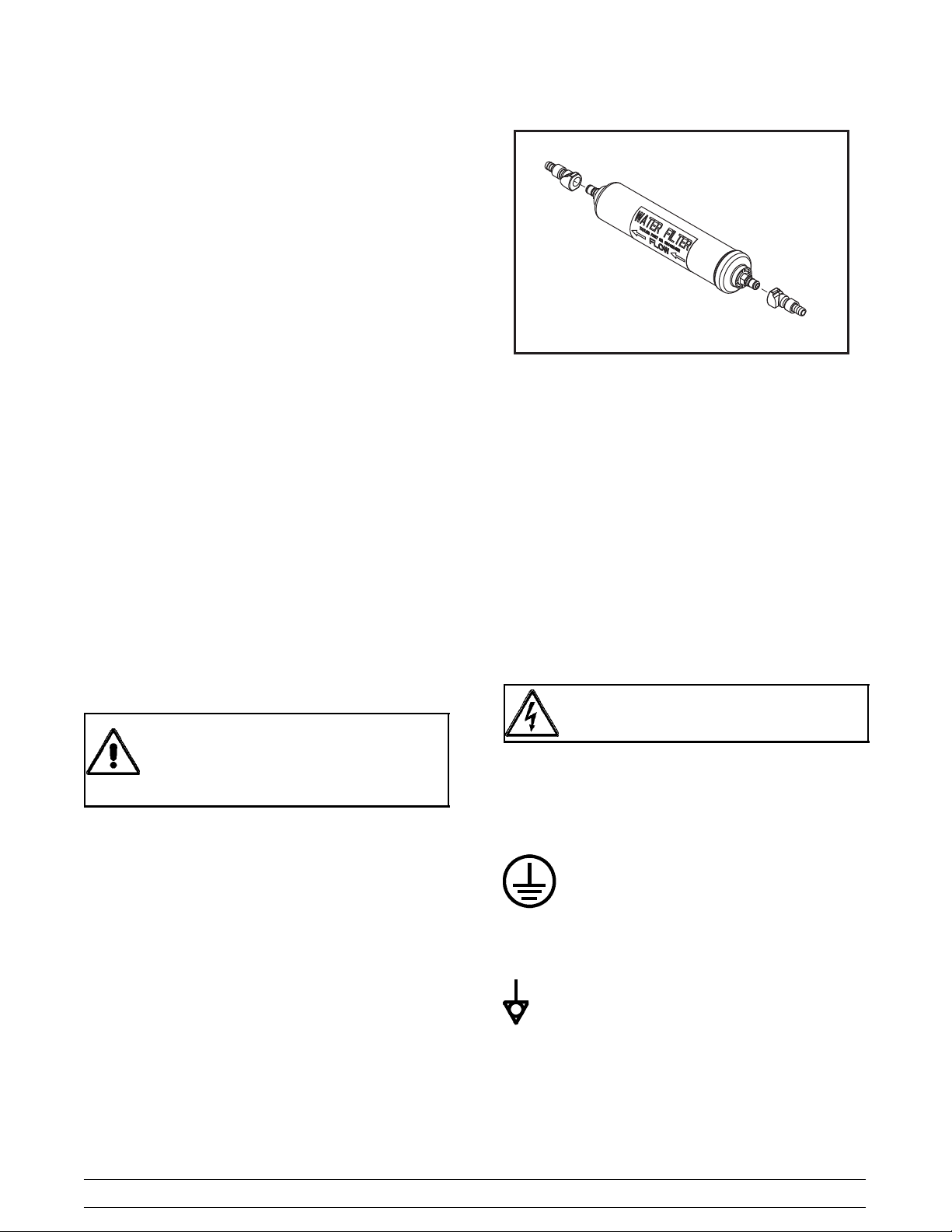
IMPORTANT: The water filter (064422--SER) must
be thoroughly flushed with water before connecting it
to the machine. This removes carbon particles that
could clog the flow control. To flush the filter,
connect the inlet end of the filter to the water supply.
Position the outlet end of the filter over an empty
pail. Open the water supply. Allow water to flow
through the filter until the water exiting the filter is
clear. Close the water supply. Attach the outlet end
of the filter to the machine. Reopen the water
supply.
Figure 1
Electrical Connections
In the United States, this equipment is intended to be
installed in accordance with the National Electrical
Code (NEC), ANSI/NFP A 70--1987. The purpose of
the NEC code is the practical safeguarding of persons
and property from hazards arising from the use of
electricity. This code contains provisions considered
necessary for safety . Compliance therewith and
proper maintenance will result in an installation
essentially free from hazard! In all other areas of the
world, equipment should be installed in accordance
with the existing local codes. Please contact your local
authorities.
FOLLOW YOUR LOCAL ELECTRICAL CODES!
Each freezer requires one power supply. Check the
data label on the freezer for fuse, circuit ampacity and
electrical specifications. Refer to the wiring diagram
provided inside of the control box, for proper power
connections.
CAUTION: THIS EQUIPMENT MUST BE
PROPERLY GROUNDED! FAILURE TO DO SO
CAN RESULT IN SEVERE PERSONAL INJURY
FROM ELECTRICAL SHOCK!
This unit is provided with an equipotential
grounding lug that is to be properly attached to the rear
of the frame by the authorized installer. The installation
location is marked by the equipotential bonding
symbol (5021 of IEC 60417-1) on both the removable
panel and the equipments frame.
080911
2
Models 345, 346, 349, 355 NPRTo the Installer
S Stationary appliances which are not
equipped with a power cord and a plug or
another device to disconnect the appliance
from the power source must have an all-pole
disconnecting device with a contact gap of
at least 3mm installed in the external
installation.
S Appliances that are permanently connected
to fixed wiring and for which leakage
currents may exceed 10 mA, particularly
when disconnected or not used for long
periods, or during initial installation, shall
have protective devices such as a GFI, to
protect against the leakage of current,
installed by the authorized personnel to the
local codes.
S Supply cords used with this unit shall be
oil-resistant, sheathed flexible cable not
lighter than ordinary polychloroprene or
other equivalent synthetic
elastomer-sheathed cord (Code designation
60245 IEC 57) installed with the proper cord
anchorage to relieve conductors from strain,
including twisting, at the terminals and
protect the insulation of the conductors from
abrasion.
Beater Rotation
Refrigerant
In consideration of our environment, Taylor
proudly uses only earth friendly HFC refrigerants. The
HFC refrigerant used in this unit is R404A. This
refrigerant is generally considered non-toxic and
non-flammable, with an Ozone Depleting Potential
(ODP) of zero (0).
However, any gas under pressure is potentially
hazardous and must be handled with caution.
NEVER fill any refrigerant cylinder completely with
liquid. Filling the cylinder to approximately 80% will
allow for normal expansion.
Refrigerant liquid sprayed onto the skin may
cause serious damage to tissue. Keep eyes and skin
protected. If refrigerant burns should occur, flush
immediately with cold water. If burns are severe, apply
ice packs and contact a physician immediately .
Taylor reminds technicians to be cautious of
government laws regarding refrigerant recovery,
recycling, and reclaiming systems. If you have any
questions regarding these laws, please contact the
factory Service Department.
Beater rotation must be clockwise as viewed
looking into the freezing cylinder.
Note: The following procedures must be
performed by an authorized Taylor service
technician.
To correct the rotation on a three-- phase unit,
interchange any two incoming power supply lines at
freezer main terminal block only.
To correct rotation on a single--phase unit, change the
leads inside the beater motor. (Follow the diagram
printedonthemotor.)
Electrical connections are made directly to the
terminal block. The terminal block is provided in the
small junction box located behind the rear panel on the
bottom of the frame. (This does not apply to the Model
355.)
Models 345, 346, 349, 355 NPR To the Installer
conjunction with polyolester oils is extremely moisture
absorbent. When opening a refrigeration system, the
maximum time the system is open must not exceed 15
minutes. Cap all open tubing to prevent humid air or
water from being absorbed by the oil.
3
WARNING: R404A refrigerant used in
080911
Syrup System Connections
1. Water pipe connections and fixtures directly
connected to a potable water supply shall be
sized, installed and maintained according to
federal, state and local laws.
2. Hook up cold water supply to freezer to supply
water to the carbonator. A minimum of 21 PSI
(1.45 BAR) of water pressure is required at the
low pressure switch. The low pressure switch
will cause the entire freezer to shut down if the
water pressure drops below 7 PSI (.483 BAR)
for longer than one minute.
3. Electrical Hook--Up
a. One power cord.
b. Refer to the data label.
c. Be sure all control switches on the front panel
are in the “OFF” position.
d. The freezer must be properly grounded.
Models 345 & 346:
Figure 2
Model 349:
5. The Model 349 has a harness with five
nylobrade tubes which feed through the base
pan and exit the rear of the freezer.
a. Connect the #1 line to the syrup supply for
the #1 freezing cylinder as viewed from the
front of the machine.
b. Connect the #2 line to the syrup supply for
the #2 freezing cylinder as viewed from the
front of the machine.
c. Connect the #3 line to the syrup supply for
the #3 freezing cylinder as viewed from the
front of the machine.
4. The Models 345 and 346 have a harness with
three nylobrade tubes which feed through the
base pan and exit the rear of the freezer.
Note: For all models, freezing cylinders are
numbered from left to right when facing the machine.
(i.e., left freezing cylinder is #1, etc.)
a. Connect the #1 line to the syrup supply for
the #1 freezing cylinder as viewed from the
front of the machine.
b. Connect the #2 line to the syrup supply for
the #2 freezing cylinder as viewed from the
front of the machine.
c. Connect the CO
that is closest to the CO
regulator). This line will supply CO
line to the CO2regulator
2
tank (primary
2
2
to the
freezer.
d. Connect the #4 line to the syrup supply for
the #4 freezing cylinder as viewed from the
front of the machine.
e. Connect the CO
that is closest to the CO
regulator). This line will supply CO
line to the CO2regulator
2
tank (primary
2
2
to the
freezer.
Figure 3
4
Models 345, 346, 349, 355 NPRTo the Installer
Model 355:
6. The Model 355 has a harness with five
nylobrade tubes which feed through the base
pan and exit the rear of the freezer.
a. Connect the #1 line to the syrup supply for
the #1 freezing cylinder as viewed from the
front of the machine.
b. Connect the #2 line to the syrup supply for
the #2 freezing cylinder as viewed from the
front of the machine.
8. Set the primary regulator on the CO
PSI (4.1 BAR).
tank to 60
2
18087
c. Connect the #3 line to the CO
is closest to the CO
This line will supply CO
tank (primary regulator).
2
2
regulator that
2
to the freezer.
d. Connect the #4 line to the water regulator on
the remote carbonator. This line monitors the
water pressure supplied to the unit.
e. Connect the line labeled “SODA” to the
remote carbonator tank.
7. There are spare CO
lines provided. For
2
Bag--in--Box syrup delivery system, connect the
spare CO
lines from the secondary regulator
2
to each “Gas In” fitting on the pumps. Set the
secondary regulator pressure to 50 PSI (3.45
BAR) depending on the length of syrup line run
to the unit.
Co2 (to other pump)
Co2 (to unit)
SYRUP (to unit)
Figure 4
18033
Figure 5
9. Set the secondary regulator on the CO
tank to
2
50 PSI (3.45 bar) for the syrup tanks or the BIB
pumps.
18088
Figure 6
10. T urn the cold water supply on.
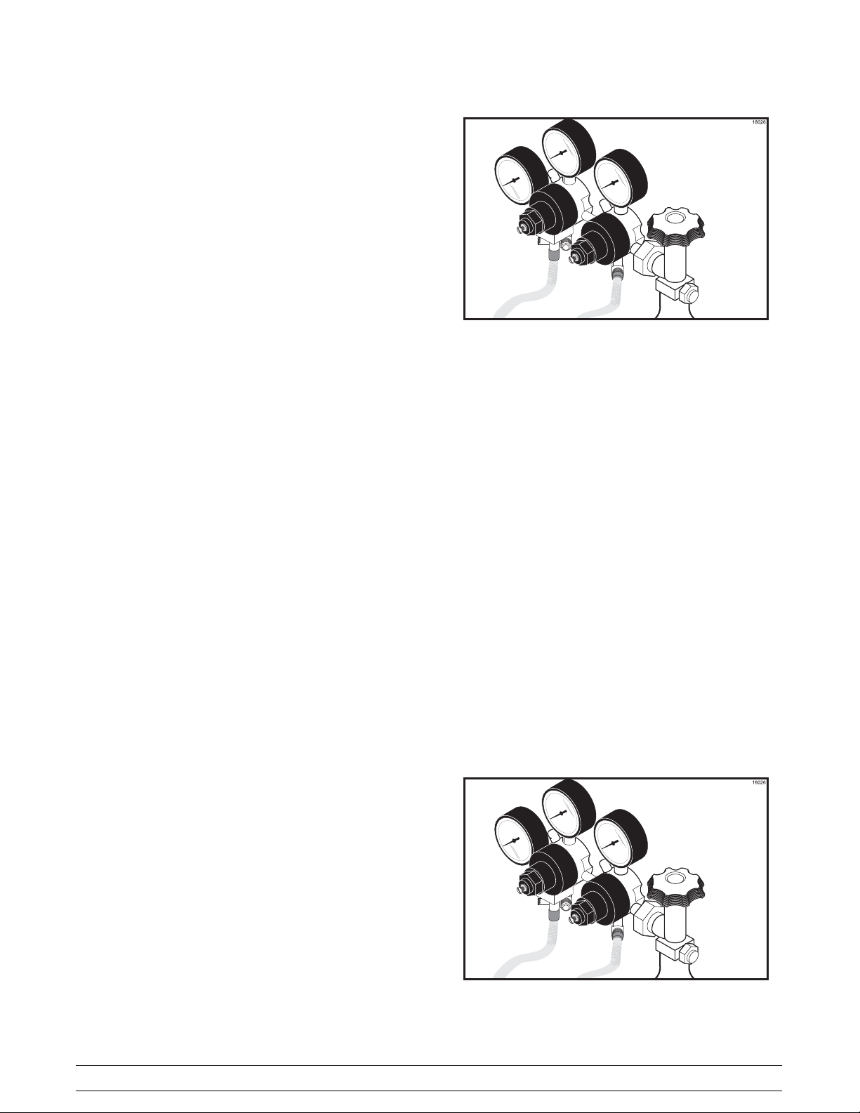
1 1. Check for CO
top of the CO
leaks. Close the valve on the
2
tank. Watch the high pressure
2
gauge. It should hold pressure. If it does not,
there is a CO
leak. Use a soap solution to
2
locate and repair the leak.
IMPORTANT: Ensure that the Bag--in--Box switch
is enabled.
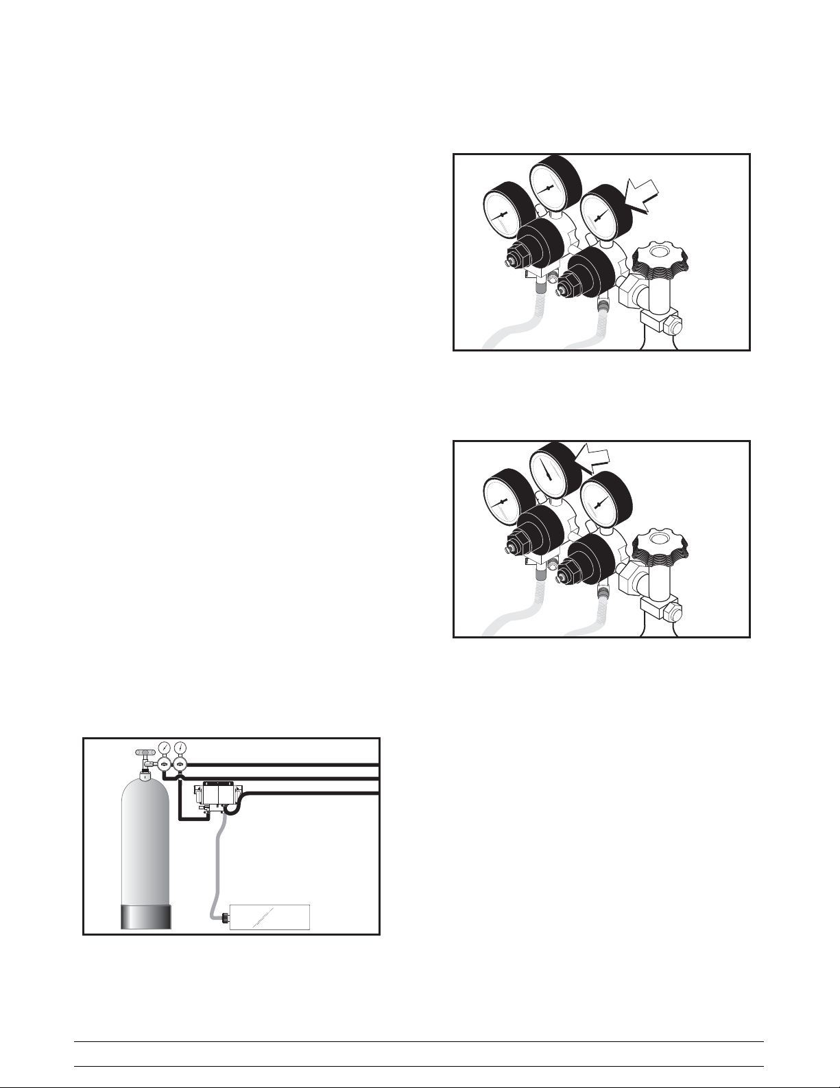
12. The CO
regulator assembly (primary regulator)
2
inside the freezer should be set at 40 -- 45 PSI
(2.76 -- 3.10 BAR).
13. The CO
low pressure switch requires at least
2
21 PSI (1.45 BAR) before the freezer will start.
It is set to cut out at 7 PSI (.483 BAR) and in at
21 PSI (1.45 BAR).
14. There are check valves in the CO
, syrup, and
2
water lines to prevent any back flow of soda
water, product, or CO
.
2
Models 345, 346, 349, 355 NPR To the Installer
5

Remote Condenser Assembly
Units
Preparation
Recommended System Refrigerant Charge
Discharge/Liquid Line
Length
Up to 50 ft. (15 m.) line sets 200 oz. / 567 kg.
Required Charge
Uncrate the condenser assemblies. After inspecting
them for damage, position them in the desired location.
Two remote condenser assemblies are required for
each freezer (one condenser per compressor).
Remote condensers require a minimum of 6”
(152 mm.) of air space on the rear and both sides.
This is required to allow for adequate air flow.
Failure to follow this instruction may cause poor
freezer performance and damage the equipment.
Refrigeration Charging and Line
Construction
Each condenser assembly is shipped with a refrigerant
holding charge sufficient to prevent moisture
contamination (8 oz./227 g. HP62). This holding
charge will become part of the total system charge.
The condenser assemblies are shipped with the total
amount of refrigerant required for a typical installation
of 50 ft. (15 m.). For other installation configurations,
use the following chart for line sizing and for adding
required refrigerant.
50 -- 75 ft. (15 -- 23 m.) 214 oz. / 607 kg.
(add 14 oz. / 40 kg.)
75 -- 100 ft. (23 -- 30 m.) 228 oz. / 646 kg.
(add 28 oz. / 79 kg.)
Note: Maximum line length is 100 ft. (30 m.) T o meet
individual installation requirements, the lines must be
purchased and constructed locally.
Line Size
Liquid Line -- Requires 3/8” refrigerant grade copper
tubing (hard or soft).
Note: Insulating the liquid line is recommended if it is
exposed to high ambient conditions. This will reduce
heat accumulation and prevent the formation of flash
gas in the liquid line.
Discharge Line -- Requires 1/2” refrigerant grade
copper tubing (hard or soft).
060801
6
Models 345, 346, 349, 355 NPRTo the Installer
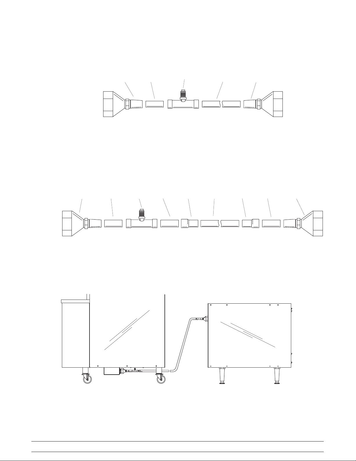
346/349 Remote Condenser Assembly Lines
Discharge
Line
Liquid
Line
5/8”
Quick
Disconnect
3/8”
Quick
Disconnect
Freezer
End
5/8”
Copper
Tubing
5/8”
Access
Te e
3/8”
Copper
Tubing
5/8”
Copper
Tubing
3/8”
Access
Te e
5/8” FS X
1/2”FS
Copper
½”
Copper
Tubing
3/8”
Tubing
Disconnect
5/8” FSX
1/2”FS
3/8”
Quick
Condenser
End
5/8”
Copper
Tubing
5/8”
Quick
Disconnect
Freezer
End
Model 346/349
Condenser
End
Condenser
Assembly
060801
Models 345, 346, 349, 355 NPR To the Installer
7
Remote Condenser Installation
Step 1
Install refrigeration lines from the freezer to the
condenser assemblies. Do not create oil traps.
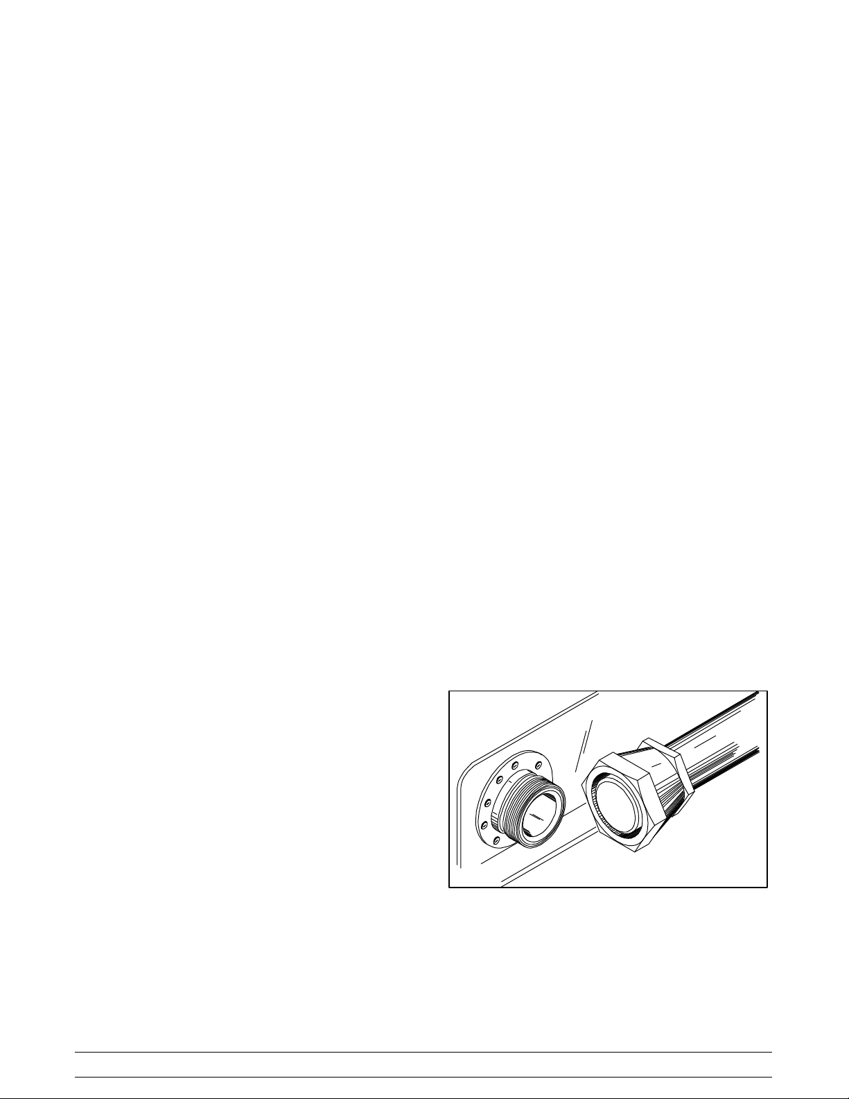
Remote Condenser Refrigeratio n
Connections
Connect the refrigerant line quick connect/disconnect
couplings (QD) to the mating QD couplings on the
condenser assembly by performing Steps 1 through 6.
When complete, repeat the instructions to connect the
couplings on the freezer.
Normally, any straight run of tubing must be supported
near each end of the run. Long runs require additional
supports. As a guide, 3/8” to 3/4” copper should be
supported every 5 ft. When changing directions, no
corner should be left unsupported. Supports should be
placed a maximum of 2 ft. in each direction from the
corner. If soft copper tube is used, make sure it is not
kinked or flattened. If hard drawn copper tubing is
used, use only long radius elbows.
Step 2
Braze the quick connect/disconnect couplings and
access tees on the freezer end of the refrigeration
lines. The couplings and access tees are supplied with
the freezer or condenser assembly.
Step 3
Braze the supplied quick connect/disconnect
couplings on the condenser assembly end of the
refrigeration lines. The couplings are supplied with the
condenser assembly.
Note: Wrap a wet cloth around the brasscoupling
bodies to prevent heat damage to the seal.
Step 1
Remove the shipping caps from the quick
connect/disconnect coupling on the condenser
assembly.
Step 2
Thoroughly clean and lubricate the mating surfaces of
the quick connect/disconnects.
Note: Use polyolester oil to lubricate the surfaces.
Step 3
Manually thread the coupling halves together to insure
proper mating of the threads.
Step 4
Using proper sized wrenches, tighten the coupling
halves until the round, flat surfaces of inner coupling
bodies completely depress one another.
Step 5
Once the flat surfaces are completely depressed,
tighten the couplings an additional 1/4 turn. This step
is necessary to insure that the knife edge of the seal
seats into the brass seat of the coupling halves,
forming a leak--proof joint (metal seal).
Step 4
Test the field constructed lines for leaks.
Step 5
Evacuate the field constructed refrigerant lines using
the access fittings brazed on the freezer end of the
refrigeration lines.
Step 6
When the evacuation process is complete, relieve the
vacuum with 4 oz. (113 g.) of HP62 refrigerant per line,
for a total of 8 oz. (227 g.) This procedure will prevent
moisture contamination during freezer and condenser
assembly connection and will complete the total
charge.
060801
Figure 7
Step 6
Check all connections for leaks.
Repeat these steps to connect the refrigerant line QD
couplings to the mating QD couplings on the freezer.
8
Models 345, 346, 349, 355 NPRTo the Installer

Section 2 To the Operator
The freezer(s) you have purchased has been carefully
engineered and manufactured to give you dependable
operation.
This unit(s), when properly operated and cared for, will
produce a consistent quality product. Like all
mechanical products, this machine will require
cleaning and scheduled maintenance. A minimum
amount of care and attention is necessary if the
operating procedures outlined in this manual are
followed closely.
This Operator’s Manual should be read before
operating or performing any maintenance on your
equipment.
Your freezer will NOT eventually compensate and
correct for any errors during the set--up or filling
operations. Thus, the initial assembly and priming
procedures are of extreme importance. It is strongly
recommended that all personnel responsible for the
equipment’s operation study these procedures
together in order to be properly trained and to make
sure that no misunderstandings exist.
In the event you should require technical assistance,
please contact your local authorized Taylor Distributor
for service.
Note: Warranty is valid only if the parts are authorized
Taylor parts, purchased from an authorized Taylor
Distributor, and the required service work is provided
by an authorized Taylor service technician. Taylor
reserves the right to deny warranty claims on
equipment or parts if non--approved parts or
refrigerant were installed in the machine, system
modifications were performed beyond factory
recommendations, or it is determined that the failure
was caused by neglect or abuse.
Note: Constant research results in steady
improvements; therefore, information in this
manual is subject to change without notice.
If the crossed out wheeled bin symbol is
affixed to this product, it signifies that this product is
compliant with the EU Directive as well as other similar
legislation in effect after August 13, 2005. Therefore,
it must be collected separately after its use is
completed, and cannot be disposed as unsorted
municipal waste.
The user is responsible for returning the product to the
appropriate collection facility, as specified by your local
code.
For additional information regarding applicable local
laws, please contact the municipal facility and/or local
distributor.
Compressor Warranty Disclaimer
The refrigeration compressor(s) on this machine are
warranted for the term indicated on the warranty card
accompanying this machine. However, due to the
Montreal Protocol and the U.S. Clean Air Act
Amendments of 1990, many new refrigerants are
being tested and developed, thus seeking their way
into the service industry. Some of these new
refrigerants are being advertised as drop-- in
replacements for numerous applications. It should be
noted that, in the event of ordinary service to this
machine’s refrigeration system, only the refrigerant
specified on the affixed data label should be used.
The unauthorized use of alternate refrigerants will void
your compressor warranty. It will be the owner’s
responsibility to make this fact known to any technician
he employs.
It should also be noted that Taylor does not warrant the
refrigerant used in its equipment. For example, if the
refrigerant is lost during the course of ordinary service
to this machine, Taylor has no obligation to either
supply or provide its replacement either at billable or
unbillable terms. Taylor does have the obligation to
recommend a suitable replacement if the original
refrigerant is banned, obsoleted, or no longer available
during the five year warranty of the compressor.
Taylor will continue to monitor the industry and test
new alternates as they are being developed. Should a
new alternate prove, through our testing, that it would
be accepted as a drop--in replacement, then the above
disclaimer would become null and void. To find out the
current status of an alternate refrigerant as it relates to
your compressor warranty , call the local Taylor
Distributor or the Taylor Factory. Be prepared to
provide the Model/Serial Number of the unit in
question.
080911
Models 345, 346, 349, 355 NPR To the Operator
9
Section 3 Safety
We at Taylor Company are concerned about the safety
of the operator when he or she comes in contact with
the freezer and its parts. Taylor has gone to extreme
efforts to design and manufacture built--in safety
features to protect both you and the service technician.
As an example, warning labels have been attached to
the freezer to further point out safety precautions to the
operator.
IMPORTANT -- Failure to adhere to the
following safety precautions may result in severe
personal injury or death. Failure to comply with
these warnings may damage the machine and its
components. Component damage will result in
part replacement expense and service repair
expense.
DO NOT operate the freezer without reading
this Operator Manual. Failure to follow this instruction
may result in equipment damage, poor freezer
performance, health hazards, or personal injury.
This unit is provided with an equipotential
grounding lug that is to be properly attached to the rear
of the frame by the authorized installer. The installation
location is marked by the equipotential bonding
symbol (5021 of IEC 60417-1) on both the removable
panel and the equipments frame.
DO NOT use a water jet to clean or rinse the
freezer. Failure to follow these instructions may result
in serious electrical shock.
S DO NOT operate the freezer unless it is
properly grounded.
S DO NOT operate the freezer with larger
fuses than specified on the freezer data
label.
S DO NOT attempt any repairs unless the
main power supply to the freezer has been
disconnected. Contact your local authorized
Taylor Distributor for service.
S Stationary appliances which are not
equipped with a power cord and a plug or
another device to disconnect the appliance
from the power source must have an all-pole
disconnecting device with a contact gap of
at least 3mm installed in the external
installation.
S Appliances that are permanently connected
to fixed wiring and for which leakage
currents may exceed 10 mA, particularly
when disconnected or not used for long
periods, or during initial installation, shall
have protective devices such as a GFI, to
protect against the leakage of current,
installed by the authorized personnel to the
local codes.
S Supply cords used with this unit shall be
oil-resistant, sheathed flexible cable not
lighter than ordinary polychloroprene or
other equivalent synthetic
elastomer-sheathed cord (Code designation
60245 IEC 57) installed with the proper cord
anchorage to relieve conductors from strain,
including twisting, at the terminals and
protect the insulation of the conductors from
abrasion.
Failure to follow these instructions may result in
electrocution. Contact your local authorized Taylor
Distributor for service.
080911
10
Models 345, 346, 349, 355 NPRSafety

S DO NOT allow untrained personnel to
operate this machine.
S DO NOT operate the freezer unless all
service panels and access doors are
restrained with screws.
S DO NOT put objects or fingers in door
spout.
S DO NOT remove the door, beater, scraper
blades, drive shaft or hopper cover unless
all control switches are in the “OFF” position
and ALL PRESSURE IN THE FREEZING
CYLINDER HAS BEEN RELIEVED.
Failure to follow these instructions may result in
contaminated product or severe personal injury to
fingers or hands from hazardous moving parts.
This freezer must be placed on a level
surface. Failure to comply may result in personal injury
or equipment damage.
Cleaning and sanitizing schedules are
governed by your state or local regulatory agencies
and must be followed accordingly. Please refer to the
cleaning section of this manual for the proper
procedure to clean this unit.
DO NOT obstruct air intake and discharge openings:
These units require 6” (152 mm) minimum air space
around all sides. Failure to follow this instruction may
cause poor freezer performance and damage to the
machine.
This unit has many sharp edges that can
cause severe injuries.
S DO NOT put objects or fingers in the door
spout. This may contaminate the product
and cause severe personal injury from blade
contact.
S USE EXTREME CAUTION when removing
the beater asssembly. The scraper blades
are very sharp.
For Indoor Use Only: This unit is designed to operate
indoors, under normal ambient temperatures of 70_ -
75_F(21_ -24_C). The freezer has successfully
performed in high ambient temperatures of
104_(40_C) at reduced capacities.
NOISE LEVEL: Airborne noise emission does not
exceed 78 dB(A) when measured at a distance of 1.0
meter from the surface of the machine and at a height
of 1.6 meters from the floor.
080911
Models 345, 346, 349, 355 NPR Safety
11
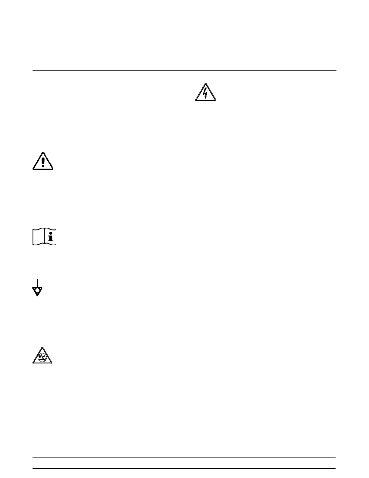
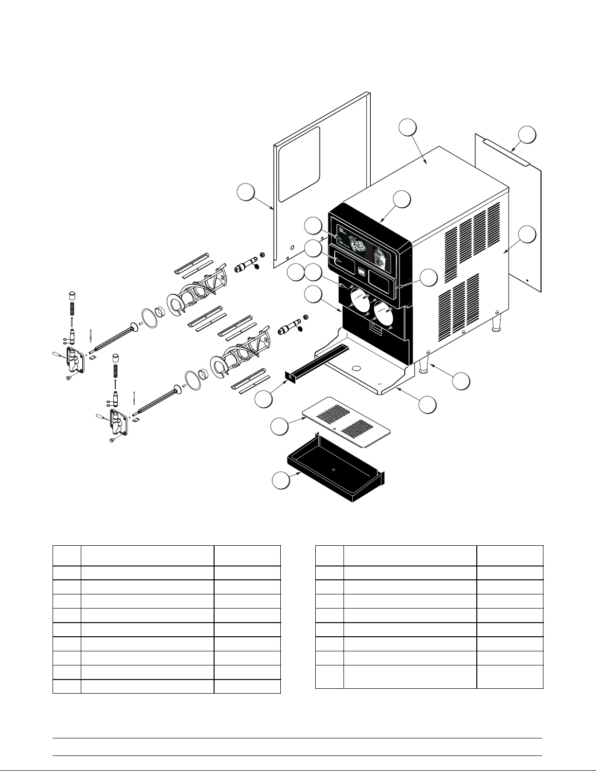
Section 4 Operator Parts Identification
Model 345
10
11
15
14
17
18
13
16
12
2
1
3
4
5
6
8
7
Item Description Part No.
1 Panel A. --Side Left X45136
2 Hood 044618
3 Panel--Rear 044921--SP1
4 Panel A. --Side Right X44919
5 Caster-- Swivel 3/4--10 St. 3” 021279
6 Caster-- Locking Swivel -- 3” 030307
7 Lock--Caster Bracket 032571
8 Shield--Splash 043719
9 Tray-- Drip *345/6* Black w/Drain 043720--SP
10 Pan--Drip 19-- 1/2 Long 035034
9
Item Description Part No.
11 Panel -- Service 044916
12 Panel--Front-- Lower 043599--BLA
13 Stud--Nose Cone 5/16--18 020445
*13a Washer--Freezer Stud 036265
14 Card-- Flavor Packet 035324
15 Card--FCB POP 043957
16 Panel--Front-- Upper 043600--BLA
17 Plate A.--Dec --345-- 346--355
Black
18 Decal-- Dec--Taylor 053761
*19 Pan--Drip (White) For Drip Guide 043612
*Not Shown
12
Models 345, 346, 349, 355 NPROperator Parts Identification
043639--BLA
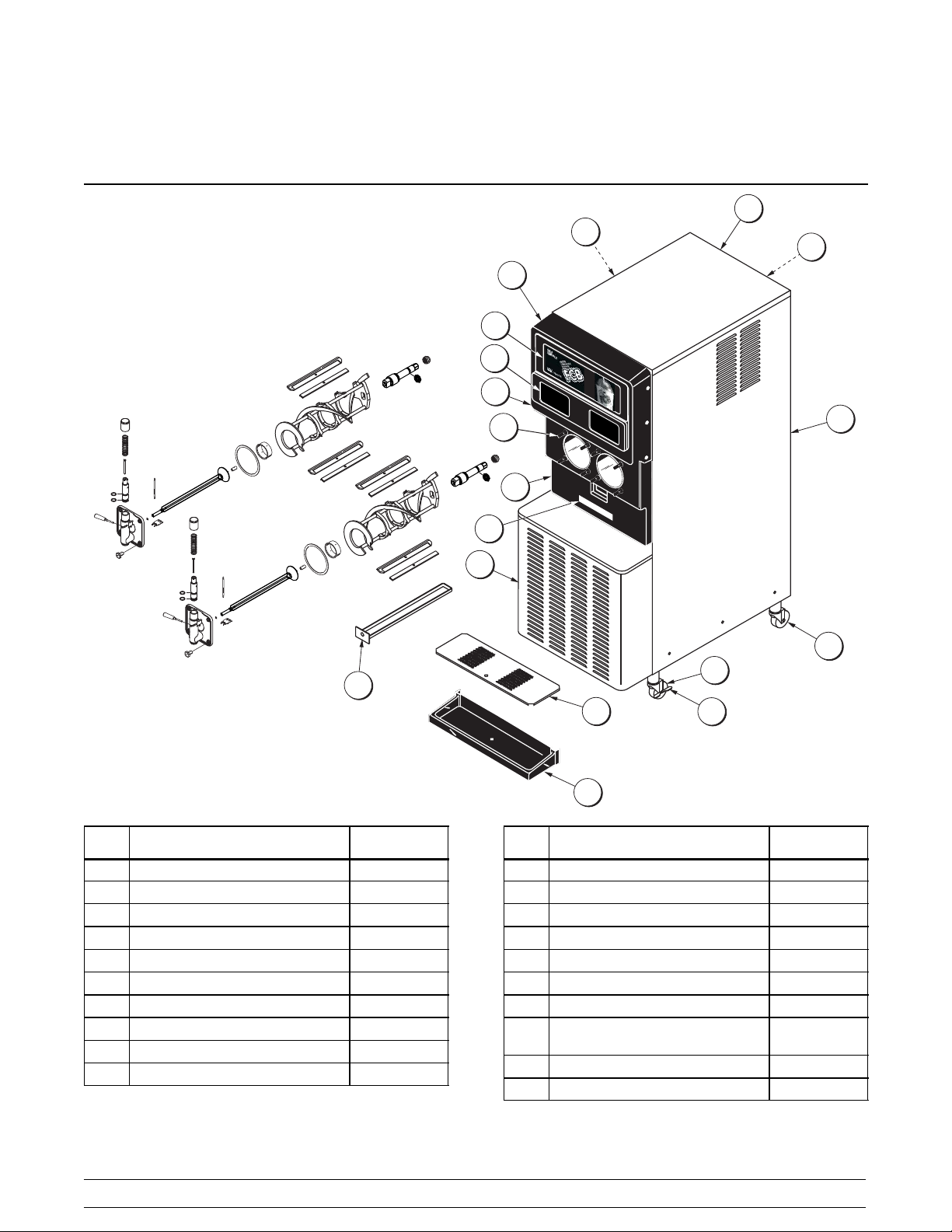
Model 346
3
2
1
15
8
10
9
Item Description Part No.
14
13
16
17
12
18
19
6
7
11
Item Description Part No.
20
4
5
1 Panel A.--Side Left X44917
2 Hood 044618
3 Panel-- Rear 044921--SP1
4 Panel A.--Side *346*AC*R*Filter X53611
5 Caster--Swivel 3/4--10 St. 3” 021279
6 Caster--Locking Swivel 3” 030307
7 Lock--Caster Bracket 032571
8 Shield--Splash 043719
9 Tray--Drip 20” L x 8” D x 3--3/4 043720--SP
10 Pan-- Drip 19-- 1/2 Long 035034
11 Panel--Service *346* Filter 053612
Models 345, 346, 349, 355 NPR Operator Parts Identification
13
12 Panel--Front--Lower 043599--BLA
13 Stud--Nose Cone 5/16--18 020445
*13a Washer--Freezer Stud 036265
14 Card--Flavor Packet 035324
15 Card-- FCB POP 043957
16 Panel--Front--Upper 043600--BLA
17 Plate-- Dec--345 --346--355* Black 043639 --BLA
18 Decal--Dec--Taylor 053761
19 Filter-- Air 18L x 16.5H x .70W AC 052779--1
20 Cover--Hole--Filter--Snap In 053801
*21 Pan--Drip (White) For Drip Guide 043612
*Not Shown
Model 349
2
17
13
15
12
14
11
1
16
10
3
4
5
6
Item Description Part No.
1 Panel A. --Side Left X42289
2 Hood 042166
3 Panel--Rear *349* Drain Hole 042198
4 Panel A. --Side Right X42291
5 Caster-- Swivel 3/4--10 St. 3” 021279
6 Caster-- Locking Swivel 3” 030307
7 Lock--Caster Bracket 032571
8 Panel--Service *349* AC 053652
9 Tray-- Drip (Blac k) w/Drain 038275--SP
10 Shield--Splash 038276
11 Panel -- Front--Lower 042082--BLA
7
18
8
9
Item Description Part No.
12 Stud--Nose Cone 5/16--18 020445
*12a Washer--Freezer Stud 036265
13 Card-- Flavor Packet 035324
14 Panel--Front Upper 042081-- BLA
15 Plate--Dec *349* Black 035410--BLA
16 Decal--Dec--Taylor 053761
17 Cover--Hole--Filter--Snap In 053801
18 Filter--Air18Lx16.5Hx.7W 052779--1
*19 PanA.--Dripw/HoseLeft X42201
*20 PanA.--Dripw/HoseRight X42203
*Not Shown
14
Models 345, 346, 349, 355 NPROperator Parts Identification
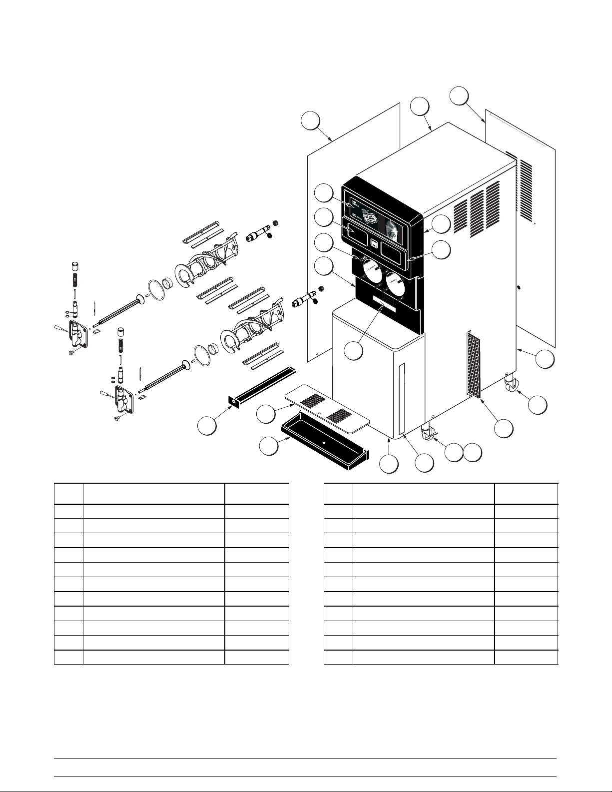
Model 355
3
2
1
4
14
5
13
12a
12
15
11
6
10
7
Item Description Part No.
1 Panel--Front --Upper 043600--BLA
2 Panel--Side--Left 044619--SP
3 Hood 044618
4 Panel--Rear--Stainless 044621--SS
5 Panel--Side--Right 044620-- SP
6 Leg--4” 3/8-- 16 Stud 036397
7 Shelf--Drip Tray 049697
8 Tray-- Drip 20” L x 8” D x 3--3/4 043720
9 Shield--Splash 043719
9
8
Item Description Part No.
10 Pan--Drip 035034
11 Panel--Front--Lower 043599SBLA
12 Stud--Nose Cone 5/16--18 020445
*12a Washer-- Freezer Stud 036265
13 Card--Flavor Packet 035324
14 Card--FCB POP 043957
15 Plate-- Dec--345-- 346--355 Black 043639--BLA
*16 Pan--Drip (White) For Drip
Guide
*Not Shown
043612
Models 345, 346, 349, 355 NPR Operator Parts Identification
15
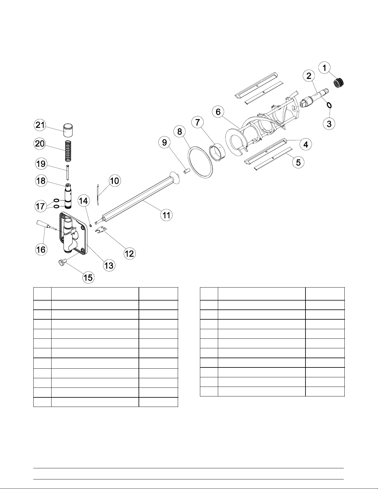
Door Assembly
Item Description Part No.
1 Seal--Drive Shaft 032560
2 Shaft--Beater 036412
3 O--Ring--7/8 OD x .139 W 025307
4 Blade--Scraper--Plastic 046237
5 Clip--Scraper Blade 046238
6 Beater A.--7 Qt. 1 Pin X46233
7 Bearing--Front 0131 16
8 Gasket--Door 5.109” ID 014030
9 Bearing--Guide 014496
10 Arm--Baffle 047729
11 Baffle Assembly X47731
Item Description Part No.
12 Buster--Ice 047735
13 Door A.--Partial X39241
14 O--Ring -- .291 ID x .080 W 018550
15 Nut--Stud 029880
16 Handle A.--Draw X47384
17 O--Ring -- 1” OD x .139 W 032504
18 Valve- -Dra w 047734--SP
19 Pin--Valve Handle 031974
20 Spring--Comp. 030344
21 Cap A.--Spring Retainer X30591
16
Models 345, 346, 349, 355 NPROperator Parts Identification
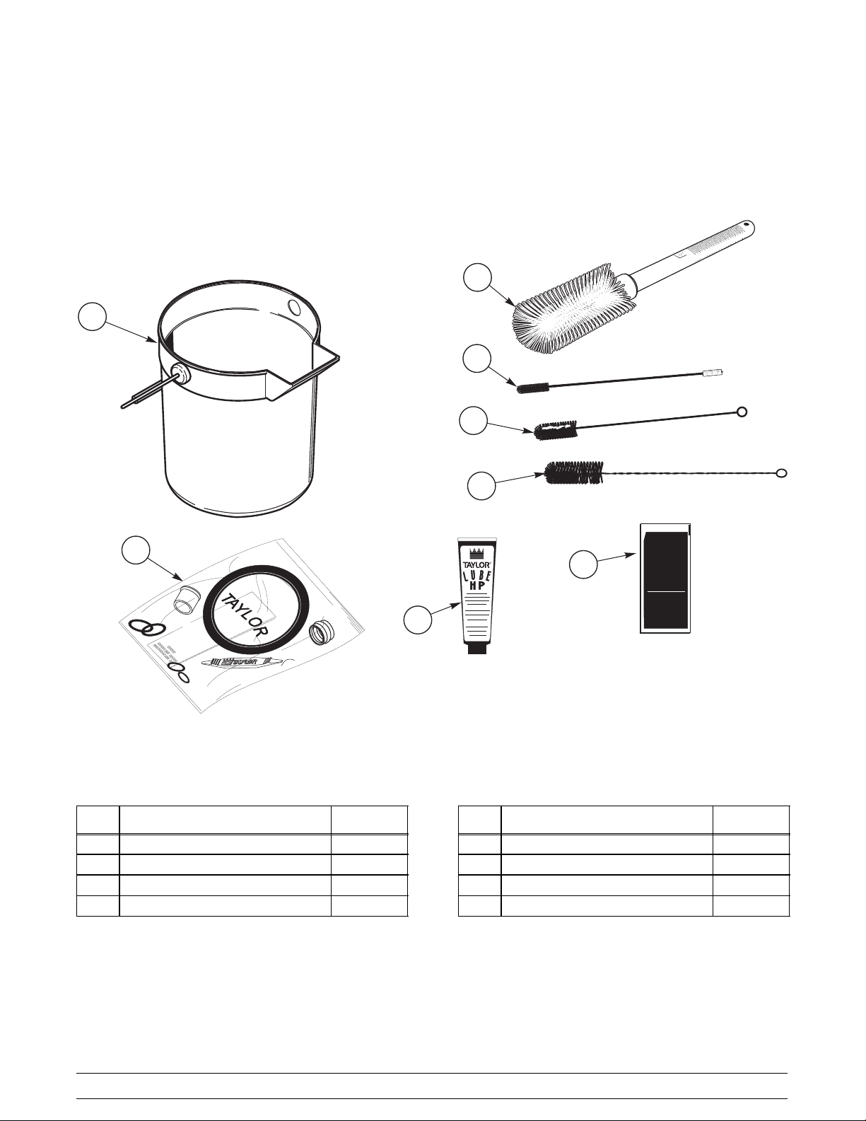
Accessories
1
2
3
4
5
6
0
6
2
8
4
0
ITEM DESCRIPTION PART NO.
1 PAIL-MIX 10 QT 013163
2 BRUSH-MIX PUMP BODY-3”X7” 023316
3 BRUSH-DOUBLE ENDED 013072
4 BRUSH-REAR BRG 1”DX2“L 013071
7
KAY-5
®
R
8
Sanitizer/Cleaner
KEEPOUT OF REACH OF CHILDREN
CAUTION
FORINSTITUTIONAL USE ONLY
1OZ (28.4 g)
ITEM DESCRIPTION PART NO.
5 BRUSH-DRAW VALVE 1-1/2”OD 014753
6 KIT A.-TUNE UP X48942
7 LUBRICANT-TAYLOR HI PERF 048232
8 SANITIZER KAY-5 25 PACKETS 041082
Models 345, 346, 349, 355 NPR Operator Parts Identification
17
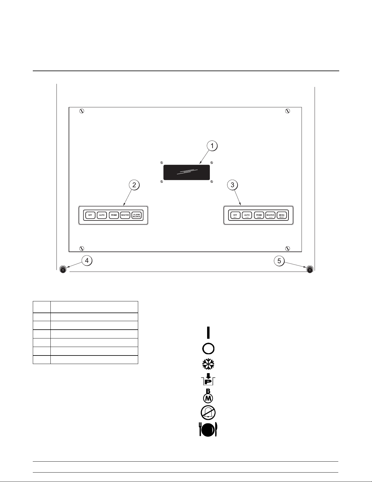
Section 5 Important: To the Operator
Item
1 Control Switch
2 Liquid Crystal Display
3 Keypad--Left
4 Keypad--Right
5 Product Light--Left Side
6 Product Light--Right Side
Description
Symbol Definitions
(Model 349 Only)
To better communicate in the International arena, the
words on many of our operator switches and keys have
symbols to indicate their functions. The Model 349 is
designed with these International symbols.
Figure 8
18
The following chart identifies the symbol definitions
used on the Model 349.
=ON
=OFF
=AUTO
=PRIME
= BEATER MOTOR
= ALARM SILENCE
= MENU/SELECT
Models 345, 346, 349, 355 NPRImportant: To the Operator

Control Switch
Pressing both AUTO keys will display this screen.
The control switch is located on top of the control box
on the models 345, 346 and 355. It is located on the
rear of the control box on the model 349. When placed
in the ON position, allows Slushtecht operation.
Liquid Crystal Display
The Liquid Crystal Display (LCD) is located on the front
control panel. The LCD is used to show the current
operating mode of the freezing cylinders. The LCD
also indicates whether there is enough syrup, CO2,
and water being supplied to the freezer. If an error in
the machine operation occurs, a warning tone will
sound and the word “FAULT” will flash on the third line
of the display.
Operational Mode Display
AUTO MODE AUTO
OK SYRUP OK
CO2=OK WATER=OK
Line 1 indicates the operating mode for each cylinder.
Line 2 indicates the status of the syrup systems in each
freezing cylinder.
Line 3 indicates if there is a fault in the system (left
side).
The same rules apply to the fourth line which indicates
the status of the CO
AUTO MODE OFF
OK SYRUP OK
-- -- F A U LT -- -CO2=OK WATER=OK
and the H2O.
2
Operator Menu Display
When the unit is plugged into the wall receptacle and
the power switch is placed in the ON position, this
screen appears.
SAFETY TIMEOUT
ANY KEY ABORTS
This display will remain on the LCD for 60 seconds
unless a key is pressed. If any key is pressed (or 60
seconds passes), then the next screen appears.
OFF MODE OFF
OK SYRUP OK
CO2=OK WATER=OK
Note: Syrup, CO2and water are satisfied.
The OPERATOR MENU is used to enter into the
operating screens. To access the OPERATOR MENU,
simply press the word “MENU”. The cursor will flash
under the letter “A”, indicating that this is screen A. To
select a different screen, use the arrow keys to move
the cursor to the desired screen selection and press
the SEL key.
OPERATOR MENU
BCDEFGH
A
EXIT MENU
<---- ----> SEL
Operator Menu Timeout
If the display is left in the operator menu or any of the
operator menu selections, except for Current
Conditions, the display will return to the system mode
screen 60 seconds after the last keypress. The
Current Conditions screen will be displayed until
manually changed.
Models 345, 346, 349, 355 NPR Important: To the Operator
19

Finding Current Fault Conditions
Screen B is FAULT DESCRIPTION. The fault
description will indicate if there is a fault in one of the
freezing cylinders. When the actual fault is
corrected,the warning tone will stop. Only items 9 and
10 require pressing the OFF/<------ key to clear the fault
message and the warning tone.
Fault Messages
No Fault Found No fault conditions are
apparent.
2. BEATER OVERLOAD -- Beater motor is out on
overload. When this fault occurs, the machine
automatically turns off. The fault clears when
the condition is corrected.
FAULT DESCRIPTION
L: BEATER OVERLOAD
R: BEATER OVERLOAD
CLR +++ SEL
Beater Overload Beater is out on overload.
Chk Refrig Sys Psi Compressor is out on high
head pressure (or low
suction pressure = option
that applies to some units)
Thermistor Short Shorted thermistor probe.
Thermistor Open Open thermistor probe.
H2O Pressure Low Water pressure is low.
CO2 Pressure Low CO2pressure is low.
Syrup Pressure Low Syrup is no longer present.
BRLTemp2High Freezing cylinder
temperature is above 120_F
(49_C).
BRL Not Cooling Freezing cylinder is not
cooling after 5 minutes.
The following are explanations of the possible faults
and the display screens.
Lines 2 and 3 indicate the faults found in the left and
right freezing cylinders respectively. The screen below
indicates that no faults exist on either side. To see if
there is more than one fault, press the +++ key.
3. CHK REFRIG SYS PSI -- Compressor is out on
high head pressure (or low suction pressure =
option that applies to some units). When this
fault occurs, it places the unit into the OFF
mode. The fault clears when the condition is
corrected.
FAULT DESCRIPTION
L: CHK REFRIG SYS PSI
R: CHK REFRIG SYS PSI
CLR +++ SEL
4. THERMISTOR SHORT -- One or both of the
barrel (freezing cylinder) thermistor probes are
faulty.
FAULT DESCRIPTION
L: THERMISTOR SHORT
R: NO FAULT FOUND
CLR +++ SEL
1. NO FAULT FOUND -- No fault conditions are
apparent.
FAULT DESCRIPTION
L: NO FAULT FOUND
R: NO FAULT FOUND
CLR +++ SEL
Note: On a Model 349, faults for freezing cylinders 1
and 2 are shown on the first screen. Press the SEL key
to read fault messages for freezing cylinders 3 and 4.
060824
5. THERMISTOR OPEN -- One or both of the
barrel (freezing cylinder) thermistor probes are
faulty.
FAULT DESCRIPTION
L: THERMISTOR OPEN
R: NO FAULT FOUND
CLR +++ SEL
20
Models 345, 346, 349, 355 NPRImportant: To the Operator

6. SYRUP PRESS LOW -- When the syrup out
indicator displays a lack of syrup, a 15 minute
internal timer will start. At this time, no
refrigeration or product flow from the flow
control will be allowed. Only the beater and
operate. If the syrup is not replenished at
CO
2
the end of the 15 minutes, the freezing cylinder
will shut down and this fault message will
appear. Replenish the syrup, and the fault
message and warning tone will clear. If using a
tank system, priming may be required.
(Example shown is for the right side.)
FAULT DESCRIPTION
L: NO FAULT FOUND
R: SYRUP PRESS LOW
CLR +++ SEL
7. CO2PRESSURE LOW -- When the CO2out
indicator displays a lack of CO
internal timer will start. If the CO
, a 60 second
2
is not
2
replenished at the end of the 60 seconds, both
freezing cylinders will shut down and this fault
message will appear. Replenish the CO
2
and
the fault message and warning tone will clear.
FAULT DESCRIPTION
L: CO2 PRESSURE LOW
R: CO2 PRESSURE LOW
CLR +++ SEL
8. H2O PRESSURE LOW -- When the water out
indicator displays a lack of water, a 60 second
internal timer will start. If the water is not
replenished at the end of the 60 seconds, all
freezing cylinders will shut down and this fault
message will appear. Replenish the water and
the fault message and warning tone will clear.
9. BRL NOT COOLING -- A freezing cylinder
check has been established for the AUTO
mode of operation. If a freezing cylinder enters
the AUTO mode, the control will check product
temperature. After five minutes, it will again
check product temperature. If product
temperature does not drop in that five minute
time span, the freezing cylinder will shut down
and this message will appear on the fault
screen. For this check to be valid, the product
temperature must be above 40_F(4.4_C), and
the fill switch cannot be activated. If a fill
condition exists during this time, the five minute
check will be re--initiated.
FAULT DESCRIPTION
L: BARREL NOT COOLING
R: NO FAULT FOUND
CLR +++ SEL
10. BRL TEMP 2 HIGH -- A maximum allowable
product temperature has been established to
prevent product from excessive heating. If the
product exceeds 120_F(49_C) temperature for
any reason (in any mode of operation), the
entire unit shuts down.
FAULT DESCRIPTION
L: BARREL TEMP 2 HIGH
R: NO FAULT FOUND
CLR +++ SEL
Faults, when corrected, are cleared from the fault
description screen, with the following exceptions:BRL
NOT COOLING and BRL TEMP 2 HIGH. These faults
require the operator to press the OFF key (when in the
FAULT DESCRIPTION screen) in order for the fault to
discontinue.
FAULT DESCRIPTION
L: H2O PRESSURE LOW
R: H2O PRESSURE LOW
CLR +++ SEL
To see if there is more than one fault in either freezing
cylinder, press the plus key . To return to the
OPERATOR MENU, press the SEL key once. To
return to the Main Screen, use the right arrow key to
cycle to MENU ITEM A, then press the SEL key.
Models 345, 346, 349, 355 NPR Important: To the Operator
21

Screen C is SET CLOCK. Move the cursor under the
number you wish to change. Press the +++ key to
increase the number; press the -- -- -- key to decrease
the number. When the desired time and date appears,
press the SEL key once to return to the OPERAT OR
MENU.
Note: The clock is programmed with military time.
SET CLOCK
:30 6/25/03
14
Repeat the procedure for the right side of the unit.
MANUAL DEFROST
RIGHT SIDE YES
<------ ------> SEL
NO
< -- -- -- -- > + + + -- -- -SEL
This screen will appear if an invalid date is entered.
(example: If the date entered exceeds the days of that
month.)
SET CLOCK
:30 02/31/04
14
INVALID DATE
SEL
This screen allows the Daylight Saving Time options.
DAYLIGHT SAVING TIME
ENABLE
<------ ------> SEL
DISABLE
If the Daylight Saving T ime option is enabled, then the
time will be advanced by one hour at 2:00 a.m. on the
first Sunday in April, and will be retarded by one hour
at 2:00 a.m. on the last Sunday in October.
Screen D is MANUAL DEFROST. This screen allows
the operator to manually defrost theleftsideofthe
unit.
Place the cursor under YES, press the SEL key, and
the command will be executed.
Note: The models 345 and 355 allow only one
freezing cylinder to be defrosted at a time. This applies
to freezing cylinder pairs on the model 349. Attempting
to place a freezing cylinder into defrost while the other
freezing cylinder is defrosting will result in the following
screen. (Model 346 does not have this restriction.)
ALREADY IN DEFROST
Press the SEL key to return the unit to the OPERATOR
MENU.
Screen E is SYSTEM INFORMATION. It consists of
6 display features.
Press the SEL key to advance to the next feature.
The first feature indicates the software version.
MANUAL DEFROST
LEFT SIDE YES
<------ ------> SEL
NO
22
SYSTEM INFORMATION
355 CONTROL UVC2
VERSION 2.00
SEL
Models 345, 346, 349, 355 NPRImportant: To the Operator

The second feature indicates the bill of material
number and the serial number.
It also indicates if the unit is equipped with a water
pressure switch.
POWER SAVER STANDBY
CYCLE 1
+ + + -- -- -- S E L
SUN 01:00
SUN 08:30
B.O.M. 035527C000
S/N K0000000
WITH H20 PRESS SW
SEL
The third feature indicates the version number of the
language and text.
SYSTEM INFORMATION
LANGUAGE
VERSION 1.05 ENGLISH 386
SEL
The fourth feature will display the Power Saver Mode,
as OFF, REST, or STANDBY.
If the Power Saver Mode is OFF, the following screen
will be displayed.
POWER SAVER MODE
OFF
SEL
The fifth feature will indicate the left side defrost
time(s) and which day(s) the defrost will occur.
Each freezing cylinder has eight possible defrost times
(cycles) for each day of the week. If all seven days
have the same time for a given cycle, then the following
screen will appear. This example shows that ALL
seven days have CYCLE 1 programmed for 9:00.
Press the +++ or -- -- -- keys to view other cycles.
DEFROST TIME LEFT
CYCLE 1
+ + + -- -- -- S E L
ALL 09:00
If one or more days of the week have a given cycle
programmed at different times, then the following
display will appear. This example shows that Sunday’s
CYCLE 1 is programmed for 9:00. The fact that SUN
is displayed (instead of ALL) indicates that some other
day(s) CYCLE 1 is programmed for a different time (or
not programmed at all). Using the cursor keys, place
the cursor under the cycle number. Press the +++ or--
-- -- keys to view other defrost times (cycles) for the day
shown. Place the cursor under the day (SUN) and
press the +++ or -- -- -- keys to access the other days
of the week.
If a Power Saver Mode is programmed, one of the
following screens will appear. (The model 349 will
display defrost information for freezing cylinders 1, 2,
DEFROST TIME LEFT
CYCLE 1
SUN 09:00
3, and 4 instead of LEFT and RIGHT.)
There are seven possible Power Saver Mode time
<------ ------> +++ ------ SEL
frames (cycles). The second display line shows the
cycle (1 of 7) as well as the time and day at which the
Power Saver Mode will begin for that cycle. The third
line shows the time and day that the Power Saver
Mode will end for that cycle. Press the +++ or -- -- -keys to view other cycles.
POWER SAVER REST
CYCLE 1
+ + + -- -- -- S E L
SUN 01:00
SUN 08:30
Models 345, 346, 349, 355 NPR Important: To the Operator
The sixth feature will indicate the right side defrost
time(s) and which day(s) the defrost will occur.
Note: The functionality is the same as described
previously for the left side defrost.
DEFROST TIME RIGHT
CYCLE 1
+ + + -- -- -- S E L
ALL 10:00
23

DEFROST TIME RIGHT
CYCLE 1
The fault description is listed on the third line of the
fault page.
SUN 10:00
<------ ------> +++ ------ SEL
Press the SEL key to return to the OPERATOR MENU.
Screen F is CURRENT CONDITIONS. This screen
displays the current viscosity and product temperature
for each freezing cylinder. An asterisk will indicate
which side is refrigerating. Press the SEL key to return
to the OPERATOR MENU.
Note: Viscosity is checked only when product
temperature is below 40
_F/4.4_C.
The following screen is exemplary of models 345, 346,
and 355. The model 349 displays all four freezing
cylinders.
CURRENT CONDITIONS
L* 999HD 27.5F
R 1200HD 26.5F
SEL
FAULT HISTORY 3
06/25/03 08:32
B H2O PRESS LOW
+ + + -- -- -- S E L
Press the MENU/SEL key to return to the OPERAT OR
MENU.
Screen H is SERVICE MENU. This screen allows the
authorized service technician to access service
information. Return to the OPERATOR MENU by
using the arrow keys to move the cursor under the
letter “A”, and press the MENU/SEL key.
OPERATOR MENU
ABCDEFG
SERVICE MENU
<------ ------> SEL
H
Screen G is FAULT HISTORY. This option provides
a record of the last 20 faults. The display also indicates
the date and time each fault occurs.
FAULT HISTORY 1
06/25/03 08:34
NO FAULT FOUND
+ + + -- -- -- S E L
Press the arrow keys to increase or decrease the fault
page.
Page numbers are located in the upper right hand
corner of the display. The most recently recorded fault
will appear on page 1.
FAULT HISTORY 2
06/25/03
R SYRUP PRESS LOW 08:33
+ + + -- -- -- S E L
Syrup Out Indicator
AUTO MODE AUTO
OUT SYRUP OK
CO2--OK WATER--OK
If the word “OUT” appears in one of the columns next
to the word “SYRUP”, it indicates a lack of syrup or
syrup pressure being supplied for the indicated
freezing cylinder. If the unit is in the AUTO or PRIME
modes, the product light will flash and a warning tone
will sound for that freezing cylinder. At this time,
replace the appropriate syrup. As a safety feature, the
refrigeration system automatically stops to prevent a
freeze--up in the freezing cylinder.
If a syrup out condition occurs on one side, that side
will enter the HOLD mode at which time refrigeration
remains off, the beater continues to run, and the
solenoid is closed for that side to prevent the
CO
2
dispensing of product. The opposite side will not be
affected.
060522
24
Models 345, 346, 349, 355 NPRImportant: To the Operator

CO2Out Indicator
AUTO MODE AUTO
OK SYRUP OK
CO2--OUT WATER--OK
On the LCD, if the word “OUT” appears next to the
word “CO2” it indicates a lack of CO2 being supplied to
the freezer. The product light will also flash and a
warning tone will sound. This will continue until the
CO2 is replaced. If the CO2 is not replaced within one
minute, the machine will shut down and a fault
message will appear.
Water Out Indicator
Audio Alarm Silencer
The audio alarm will be disabled if the ALARM
SILENCE key is pressed. If a new fault or fault
condition occurs or the system mode changes, the
audio alarm will be re--enabled automatically. If the
audio alarm is silenced for greater than 30 minutes
without correcting the fault, it will be re--enabled
automatically.
Product Light
When the light is flashing, it indicates that the product
is not at serving viscosity. This will occur during the
initial freeze down, a defrost cycle, a FAULT condition,
during power saver modes or any time the product
temperature is above 32°F(0°C).
AUTO MODE AUTO
OK SYRUP OK
CO2--OK WATER--OUT
On the LCD, if the word “OUT” appears next to the
word “WATER”, it indicates a lack of water being
supplied to the freezer. In addition, the product light will
flash and a warning tone will sound. This will continue
until the proper amount of water is supplied to the
freezer. If the water is not supplied within one minute,
the machine will shut down and a fault message will
appear.
Sampling Valve
The sampling valve is located behind the front driptray.
The sampling valve is used to obtain a brix reading.
Daily Procedures
The following procedure should be performed daily.
Remove the splash shield, front drip tray and center
drip pan. Take these parts to the sink and brush--clean
them. Re--install the parts onto the freezer.
Models 345, 346, 349, 355 NPR Important: To the Operator
25

Section 6 Operating Procedures
The Models 345, 346 and 355 contain two 7 quart (6.6
liter) freezing cylinders. The Model 349 contains four
7 quart (6.6 liter) freezing cylinders.
CAUTION: This unit is pressurized when
in operation. The control switch, located on the top
side of the control box must be in the OFF position until
the unit is completely assembled. No part should ever
be removed from the machine while it is in operation.
No parts should be removed until the control switch
has been turned to the OFF position and all pressure
has been relieved at the draw handle.
The syrup flow controls combine the two ingredients of
soda water and syrup, and send this combination to
the mix hoppers. As product is drawn, new product
from the hopper will flow through a mix feed tube down
into the freezing cylinder. The mix hopper is supplied
with 20 pounds of CO
product.
We begin our instructions at the point where the parts
are disassembled and laid out to air dry.
gas for dispensing the finished
2
Assembly
MAKE SURE THE CONTROL SWITCH IS
IN THE OFF POSITION. Failure to follow this
instruction may result in severe personal injury
from hazardous moving parts.
Note: When lubricating parts, use an approved food
grade lubricant (example: Taylor Lube HP).
Step 1
Slide the o--ring into the first groove on the drive shaft.
Lubricate the groove, o--ring, the area where the boot
seal snaps onto the drive shaft, and the shaft portion
that comes in contact with the bearing on the beater
drive shaft. DO NOT lubricate the hex end of the
drive shaft.
Slide the seal over the shaft and groove until it snaps
into place. Pinch the boot seal and fill the inside portion
of the seal with 1/4” more lubricant.
The following procedures will show you how to
assemble the parts into the freezer, sanitize them, and
prime the freezer with fresh product.
Duplicate the following procedures, where they apply,
for the remaining f reezing cylinder(s).
If you are disassembling the machine for the first time
or need information to get to this starting point in our
instructions, turn to page 37 , “Disassembly” and start
there.
Figure 9
26
Models 345, 346, 349, 355 NPROperating Procedures

Step 2
Insert the drive shaft into the freezing cylinder, (hex
end first) and into the rear shell bearing, until the seal
fits securely over the rear shell bearing. Be certain the
drive shaft fits into the drive coupling without binding.
Step 4
Holding the blades in position, insert the beater
assembly into the freezing cylinder and slide it into
position over the drive shaft. Turn the beater slightly to
be certain that the beater is properly seated. When in
position, the beater will not protrude beyond the front
of the freezing cylinder.
Figure 10
Step 3
Check the scraper blade for any nicks or signs of wear.
If any nicks are present, replace the blade. If the blade
is in good condition, place the clip over the blade. Place
the rear scraper blade and clip over the single holding
pin on the beater (knife edge to the outside). Holding
the blade on the beater, turn it over and install the front
blade the same way.
Figure 11
Figure 12
Step 5
Install the white, plastic guide bearing on the short end
of the torque rotor. Slide the o--ring into the groove on
the long end of the torque rotor and lubricate the
o--ring. Do not lubricate the guide bearing.
Figure 13
Step 6
Insert the short end of the torque rotor into the pilot
hole in the center of the drive shaft. The hole in the
torque rotor shaft should be rotated to the 12 o’clock
position.
Models 345, 346, 349, 355 NPR Operating Procedures
27

Step 7
Assemble the freezer door with the “Ice Buster” (door
spout clearing device). To assemble the door with the
ice buster, install the o--rings on the draw valve and
lubricate.
Figure 14
11261
90
Figure 16
Step 10
Insert the ice buster through the door spout and into
the slot located just above the lower o--ring.
11262
Step 8
Insert the draw valve into the door.
11122
Figure 15
Step 9
Rotate the draw valve so the groove on the top of the
draw valve is perpendicular to the door face.
Figure 17
Step 11
With the ice buster in place, rotate the draw valve to
allow installation of the draw handle. This will lock the
ice buster in place. With the draw handle in place,
install the draw handle pin. Close the draw valve by
moving the handle to the left.
11263
Figure 18
28
Models 345, 346, 349, 355 NPROperating Procedures

Step 12
Install the draw valve spring and cap.
11268
Step 14
Slide the white, plastic front bearing onto the bearing
hub, making certain that the flanged end of the bearing
is resting against the freezer door. DO NOT lubricate
the door gasket or front bearing.
11265
Figure 21
Figure 19
Step 13
Place the large rubber gasket into the groove on the
back side of the freezer door.
11264
Figure 20
Step 15
Position the freezer door onto the four studs on the
front of the freezing cylinder and push the door into
place. Install the four handscrews onto the studs and
tighten them equally in a crisscross pattern to insure
that the door is snug. DO NOT over--tighten the
handscrews.
Note: If the freezer door does not fit into place easily,
position the open end of the beater assembly in the 11
o’clock position.
11266
Figure 22
Models 345, 346, 349, 355 NPR Operating Procedures
29

Step 16
Position the torque arm by inserting it down into the
hole on the torque rotor which protrudes from the door.
Verify proper installation by moving the torque rotor
back and forth to be sure it moves freely.
11267
12184
Figure 25
Repeat Steps1 through 18 for the remaining freezing
cylinder(s).
Step 19
Install the center drip pan through the front of the
machine.
Figure 23
Step 17
Place the o--ring into the groove of the hopper cover.
12183
Figure 24
Sanitizing
Note: If a unit is sanitized, and will not be used for an
extended period of time, clean water should be used
to flush all sanitizer from the lines prior to storage of the
unit. Upon return to service, the unit must be sanitized
prior to use.
Step 1
Open the lighted display door. Remove the hood and
the side panels to gain access to the hoppers. Place
the control switch in the ON position.
Step 18
Install the hopper cover. Lock it into place.
30
Figure 26
Models 345, 346, 349, 355 NPROperating Procedures

Step 2
Prepare a pail of approved 100 PPM sanitizing solution
(examples: 2--1/2 gal. [9.5 liters] of Kay--5R or 2 gal.
[7.6 liters] of Stera--SheenR). USE WARM WATER
AND FOLLOW THE MANUFACTURER’S
SPECIFICATIONS.
IMPORTANT: Make sure the sanitizer is
completely dissolved.
Note: If your freezer uses syrup tanks, replace
Steps 3 -- 5 with the instructions on page 31.
Step 3
BaginBoxUnitsOnly:Using an empty bag of syrup,
cut the syrup line connection from the end of the bag.
Figure 27
Step 5
With the bag connector attached to the syrup line,
place the syrup line into the pail of sanitizing solution.
Figure 29
Replace Steps 3 -- 5 for Syrup Tank Units: Pour the
solution into a clean, empty syrup tank. Place the
syrup tank cover in position. Remove the CO
line and
2
syrup line number one from the syrup tank for freezing
cylinder number one. Connect these lines to the spare
syrup tank filled with sanitizing solution.
Step 4
Connect the syrup line to the syrup connection that
was cut from the syrup bag.
Figure 28
Figure 30
080911
Models 345, 346, 349, 355 NPR Operating Procedures
31

Step 6
Press the PRIME key. This will cause the sanitizing
solution to flow through the lines and into the mix
hopper.
Figure 31
Step 10
With the brushes provided, brush--clean the mix
hopper, mix inlet hole, mix level float switch, product
fitting, and the mix feed tube. Use caution when
cleaning the float switch so as not to damage it.
Step 7
Place a mix pail beneath the sampling valve which is
located behind the front drip tray. Slowly open the
sampling valve and allow sanitizer to flow through this
line and into the pail. After approximately 1/2 gallon of
sanitizer has been dispensed, close the valve.
Step 8
Prepare a pail of approved 100 PPM sanitizing solution
(examples: 2--1/2 gal. [9.5 liters] of Kay--5R or 2 gal.
[7.6 liters] of Stera--SheenR). USE WARM WATER
AND FOLLOW THE MANUFACTURER’S
SPECIFICATIONS.
Step 9
With the pail beneath the door spout, open the draw
valve and relieve all pressure from the freezing
cylinder. Remove the hopper cover. Slowly pour the
sanitizing solution into the mix hopper until the hopper
becomes 1/4 full of sanitizing solution.
Figure 33
Figure 34
080911
Figure 32
32
Figure 35
Models 345, 346, 349, 355 NPROperating Procedures

12184
Figure 36
Figure 37
Step 11
Install the mix feed tube into the mix inlet hole in the
bottom of the mix hopper.
Figure 39
Step 13
Press the BEATER key. Agitate the solution in the
freezing cylinder for five minutes.
Figure 40
Step 14
With a pail beneath the door spout, open the draw
valve and drain all the solution from the mix hopper and
the freezing cylinder. Press the OFF key and close the
draw valve.
Figure 38
Step 12
Sanitize and install the hopper cover. Lock the cover
into place. Position the open end of the vinyl tube into
the rear drip pan.
Models 345, 346, 349, 355 NPR Operating Procedures
33
Figure 41

Step 15
Disconnect the syrup connector in the sanitizing
solution.
Repeat Steps2 through 14 for the remaining freezing
cylinder(s).
Step 16
Remove the right side panel and install the rear white
drip pan.
Priming/Brixing
Step 1
Connect the syrup line to the Bag--in--Box (or the syrup
tank).
Step 2
Slowly open the syrup sampling valve and let it run into
a pail until all the sanitizer is removed and full strength
product is flowing. Do not open the valve so much that
the syrup line to the hopper is drained.
Allow the product to flow over the refractometer. The
brix reading should register 13 to 14. A reading higher
than this would cause a darker, richer product. The
refrigeration system would have to run longer to freeze
this excess syrup. A reading lower than this could
cause a freeze--up in the freezing cylinder because of
the excess water.
Figure 43
To adjust the brix, turn the adjustment screw located
in the service panel. Clockwise adjustments increase
the amount of syrup to water, and counterclockwise
adjustments decrease the amount of syrup to water.
Adjust the screw in small increments and check the
brix again.
Figure 42
Brix is the ratio of syrup to water which will directly
affect the quality and taste of the product. Brixing
should be done before priming the freezer and when
a change in syrup flavor has been made.
031216
Figure 44
Repeat this step until a correct brix reading is
registered.
34
Models 345, 346, 349, 355 NPROperating Procedures

Step 3
Once the proper brix has been achieved, close the
sampling valve. Install the front drip tray and the splash
shield on the front of the freezer.
10424
Figure 45
Step 4
With a pail beneath the door spout, press the BEATER
key. Open the draw valve and drain the freezing
cylinder. Close the draw valve. Press the PRIME key.
This will cause the product to flow to the mix hopper.
90 Day Closing Procedure
We recommend that the machine be completely
disassembled and cleaned at least every ninety days
using the following procedures.
ALWAYS FOLLOW LOCAL HEALTH CODES
To disassemble a freezer, the following items will be
needed:
S Two cleaning pails
S Necessary brushes (provided with freezer)
S Cleaner
S Single service towels
Repeat Steps 1 through 4 for the remaining freezing
cylinder(s).
Step 5
To place the freezing cylinder in the AUTO mode,
press the AUTO key. When the unit cycles off, the
product will be at serving viscosity.
Figure 46
Repeat this step for the remaining freezing
cylinder(s).
Draining Product From the
Freezing Cylinder
Step 1
Press the BEATER key. This will allow the beater to
operate. Open the draw valve and drain the product
from the machine.
Step 6
Replace the side panels.
Models 345, 346, 349, 355 NPR Operating Procedures
35
Figure 47

Step 2
When all the product has been drained from the mix
hopper and the freezing cylinder , close the draw valve
and press the OFF key. Discard this product.
Figure 48
Step 5
Remove the front drip tray. Place a mix pail beneath
the sampling valve located behind the front drip tray.
Slowly open the sampling valve and allow cleaner to
flow through this line and out into the pail. After
approximately 1/2 gallon of cleaner has been
dispensed, close the valve.
Step 6
Place an empty pail under the door spout. Remove the
hopper cover and the mix feed tube. Take these parts
to the sink for cleaning.
Step 7
Prepare a pail of approved 100 PPM cleaning solution
(examples: 2--1/2 gal. [9.5 liters] of Kay--5R or 2 gal.
[7.6 liters] of Stera--SheenR). USE WARM WATER
AND FOLLOW THE MANUFACTURER’S
SPECIFICATIONS.
Repeat Steps 1 and 2 for the remaining freezing
cylinder(s).
Cleaning
Step 1
Remove the decorative plate from the machine.
Remove the hood and side panels to gain access to
the hoppers.
Step 2
Prepare a pail of approved 100 PPM cleaning solution
(examples: 2--1/2 gal. [9.5 liters] of Kay--5R or 2 gal.
[7.6 liters] of Stera--SheenR). USE WARM WATER
AND FOLLOW THE MANUFACTURER’S
SPECIFICATIONS.
Important: Make sure the cleaner is completely
dissolved.
Step 3
Pour the solution into a clean, empty pail. Place the
syrup line with old syrup connection into the pail of
sanitizer.
Step 4
Press the PRIME key. This will cause the cleaning
solution to flow through the lines and into the mix
hopper.
Step 8
Slowly pour the cleaning solution into the mix hopper
until the hopper becomes 1/4 full of cleaning solution.
Step 9
With the brushes provided, brush--clean the mix
hopper, mix inlet hole, mix level float switch, and
product fitting. Use caution when cleaning the float
switch. Failure to do so will cause damage to the
component.
Step 10
Clean and install the hopper cover. Lock the cover into
place.
Step 11
Press the BEATER key to agitate the solution in the
freezing cylinder.
Step 12
With a pail beneath the door spout, open the draw
valve and drain all the solution from the mix hopper and
the freezing cylinder. Press the OFF key and close the
draw valve.
Step 13
Disconnect the syrup connector.
Repeat Steps2 through 13 for the remaining freezing
cylinder(s).
080911
36
Models 345, 346, 349, 355 NPROperating Procedures

Disassembly
Step 1
Be sure the control switch is in the OFF position.
Step 2
Remove the following parts from the freezer and take
them to the sink for brush--cleaning: handscrews,
freezer doors, baffle assemblies, beater assemblies
and scraper blades, drive shafts, hopper covers, front
drip tray, and the splash shield.
Brush Cleaning
Step 1
Prepare a sink with an approved cleaning solution.
USE WARM WATER AND FOLLOW THE
MANUFACTURER’S SPECIFICATIONS (examples:
Kay--5R or Stera--SheenR). IMPORTANT: Follow
the label directions. Too STRONG of a solution can
cause parts damage, while too MILD of a solution will
not provide adequate cleaning. Make sure all brushes
provided with the freezer are available for brush
cleaning.
Step 2
Return to the freezer with a small amount of cleaning
solution. With a single service towel, wipe clean the
bearing surface. Brush--clean the rear shell bearings
at the back of the freezing cylinders with the black
bristle brush.
Step 3
Remove the rear drip pan. (Does not apply to the
Model 349.)
Step 4
Remove the right side panel and take the rear, white
drip pan to the sink for further cleaning.
Step 5
Remove the following parts: seals and o--rings from
the drive shafts, drive shaft seals, caps and springs
from freezer doors, screws, draw handle slides and ice
buster from freezer doors, pivot pins from draw valves,
draw valve handles from freezer doors, draw valves
from freezer doors, o--rings from draw valves, o--rings
and front bearings from freezer doors, o--rings from
mix hopper covers.
Discard all o--rings and replace them with new ones.
Note: To remove o--rings, use a single service towel
to grasp the o--ring. Apply pressure in an upward
direction until the o--ring pops out of its groove. With
the other hand, push the top of the o--ring forward. It
will roll out of the groove and can be easily removed.
If there is more than one o--ring to be removed, always
remove the rear o--ring first. This will allow the o--ring
to slide over the forward rings without falling into the
open grooves.
Step 6
Using a single service towel, wipe the lubricant off the
parts. Brush-- clean all disassembled parts in the
cleaning solution. Make sure all lubricant and syrup is
removed. Place all the cleaned parts on a clean, dry
surfacetoair--dry.
Step 7
Wipe clean all the exterior surfaces of the freezer.
Figure 49
080318
Models 345, 346, 349, 355 NPR Operating Procedures
37

Section 7 Important: Operator Checklist
During Cleaning and Sanitizing
ALWAYS FOLLOW LOCAL HEALTH CODES
Cleaning and sanitizing schedules are governed by
your State or local regulatory agencies and must be
followed accordingly. The following check points
should be stressed during the cleaning and sanitizing
operations.
WE RECOMMEND CLEANING AND SANITIZING
EVERY 90 DAYS.
T roubleshooting Bacterial Count
j 1. Thoroughly clean and sanitize the machine
regularly, including complete disassembly and
brush cleaning.
j 7. Clean and sanitize the syrup lines regularly to
prevent syrup residue build-- up that would
restrict the proper flow of syrup.
j 8. On a regular basis, take a brix reading to assure
a consistent quality product.
Regular Maintenance Checks
j 1. Replace scraper blades that are nicked,
damaged or worn down.
j 2. Before installing the beater, be certain that the
scraper blades are properly attached over the
pins.
j 2. Use all brushes supplied for thorough cleaning.
The brushes are specially designed to reach all
product passageways.
j 3. Use the white bristle brush to clean the mix inlet
hole which extends from the mix hopper down
to the rear of the freezing cylinder.
j 4. Use the black bristle brush to thoroughly clean
the rear shell bearing located at the rear of the
freezing cylinder. Be sure there is a generous
amount of cleaning solution on the brush.
j 5. Using a screwdriver and a cloth towel, keep the
rear shell bearing and the female hex drive
socket clean and free of lubricant and product
deposits.
j 6. Properly prepare the cleaning and sanitizing
solutions. Read and follow the label directions
carefully. Too strong of a solution may damage
the parts and too weak of a solution will not do
an adequate job of cleaning or sanitizing.
j 3. Check the rear shell bearing for signs of wear
(excessive product leakage from the rear drip
pans to the front drip tray).
j 4. Dispose of o--rings or seals if they are worn,
torn, or fit too loosely, and replace with new
ones.
j 5. Follow all lubricating procedures as outlined in
“Assembly”.
j 6. Check the condenser(s) for accumulation of dirt
and lint. Dirty condensers will reduce the
efficiency and capacity of the machine.
Condensers should be cleaned monthly by
removing the poly--flo filter and cleaning it.
Remove the service panel and side panels to
expose the condenser(s). Never use
screwdrivers or other metal probes to clean
between the fins.
38
Models 345, 346, 349, 355 NPRImportant: Operator Checklist

Winter Storage
If the place of business is to be closed during the winter
months, it is important to protect the freezer by
following certain precautions, particularly if the
building is subject to freezing conditions.
Disconnect the freezer from the main power source to
prevent possible electrical damage.
Your local Taylor Distributor can perform this service
for you.
Wrap detachable parts of the freezer such as the
beater, the scraper blades, the drive shaft, and the
freezer door. Place these parts in a protected, dry
place. Rubber trim parts and gaskets can be protected
by wrapping them with moisture--proof paper . All parts
should be thoroughly cleaned of dried mix or
lubrication which attract mice and other vermin.
Note: It is recommended that an authorized service
technician perform winter storage draining, to insure
all water has been removed. This will guard against
freezing and rupturing of the components.
Models 345, 346, 349, 355 NPR Important: Operator Checklist
39

Section 8 Troubleshooting Guide
PROBLEM PROBABLE CAUSE REMEDY PAG E
REF.
1. Product is too stiff. a. Too much water to syrup
ratio. Improper brix
a. Adjust the brix
accordingly.
adjustment.
b. Consistency control needs
adjustment.
c. Torque coupling bound in
WARM position.
b. Contact a service
technician.
c. Contact a service
technician.
2. Product is too soft. a. Freezer in a defrost cycle. a. Wait for defrost cycle to
end.
3. No product is being
dispensed.
4. Freezer will not operate in
the BEATER or AUTO
b. Consistency control needs
adjustment.
c. Torque coupling bound in
COLD position.
d. Broken springs in torque
coupling.
a. Product frozen--up in
freezing cylinder.
a. Unit is unplugged. a. Check the plug at wall
b. Contact a service
technician.
c. Contact a service
technician.
d. Contact a service
technician.
a. See problem No. 1.
receptacle.
mode.
b. Blown fuse, or the circuit
breaker is off.
c. Beater motor is out on
overload. Check fault
description screen.
b. Replace the fuse or turn
the breaker on.
c. Allow the motor to cool.
Press the AUTO key. Call
a service technician if the
beater motor goes out on
overload again.
34
-- -- --
-- -- --
-- -- --
-- -- --
-- -- --
-- -- --
-- -- --
-- -- --
-- -- --
20
5. No compressor operation
in the AUTO mode.
a. Beater motor is out on
overload. Check the fault
description screen.
a. Allow the motor to cool.
Press the AUTO key. Call
a service technician if the
beater motor goes out on
overload again.
b. The torque coupling is
bound in the COLD
b. Contact a service
technician.
position.
c. Condenser dirty, A/C. c. Clean condenser monthly.
d. Water supply off, W/C. d. Turn the water on.
40
Models 345, 346, 349, 355 NPRTroubleshooting Guide
20
-- -- --
38
-- -- --

PROBLEM PROBABLE CAUSE REMEDY PAG E
REF.
6. Unable to remove the
drive shaft from the rear
shell bearing.
a. Rounded corners of hex
end of drive shaft, drive
coupling, or both.
a. Replace the drive shaft, or
call a service technician to
replace the direct drive
unit.
b. Lubrication of hex end of
drive shaft.
b. Do not lubricate the hex
end. If necessary, contact
a service technician for
removal.
7. Excessive loss of CO2. a. Leak in the CO2system. a. Contact a service
technician.
8. Leakage from rear drip
pan(s) into front drip tray.
a. Seal or o--ring on drive
shaft is worn, missing, or
a. Replace or install correctly
on drive shaft.
incorrectly installed.
b. Worn rear shell bearing. b. Contact a service
technician to replace rear
shell bearing.
9. Excessive mix leakage
from door spout.
a. Inadequate lubrication of
draw valve o--rings.
b. Wrong type lubricant on
draw valve o--rings.
a. Lubricate properly.
b. Use food grade lubricant
(example: Taylor Lube
HP).
c. Worn or missing draw
valve o--rings.
10. Unable to adjust brix. a. Syrup lines need to be
cleaned and sanitized.
c. Replace or install o--rings
on draw valve.
a. Clean and sanitize syrup
lines.
b. Blocked flow control. b. Contact a service
technician.
1 1. Lack of syrup being
supplied to machine.
a. Loss of CO2to propel
syrup.
b. Clogged or kinked syrup
lines.
a. Contact a service
technician.
b. Sanitize syrup lines
regularly. If kinked, repair
or replace.
12. Product does not enter
mix hopper.
13. Carbonated water or
sulfuric aroma is evident
in the faucet or sewage
a. Machine is not in the
AUTO or PRIME mode.
b. The mix level float switch
is inoperative.
a. Faulty check valve in
carbonation system.
a. Place the machine in the
AUTO or PRIME mode.
b. Contact a service
technician.
a. Call a service technician
to replace the check
valve.
system.
-- -- --
26
-- -- --
26
-- -- --
28
26
26 / 42
-- -- --
-- -- --
-- -- --
-- -- --
35
-- -- --
-- -- --
Models 345, 346, 349, 355 NPR Troubleshooting Guide
41

Section 9 Parts Replacement Schedule
PART DESCRIPTION EVERY 3 MONTHS EVERY 6 MONTHS ANNUALLY
Scraper Blade X Minimum
Drive Shaft Seal X
Drive Shaft O--Ring X
Freezer Door O--Ring X
Draw Valve O--Ring X
Door Spout O-- Ring X
Hopper Cover O--Ring X
Front Bearing X
Black Bristle Brush, 1” x 2” Inspect & Replace if
Necessary
Double Ended Brush Inspect & Replace if
Necessary
White Bristle Brush, 1--1/2” x 2” Inspect & Replace if
Necessary
White Bristle Brush, 3” x 7” Inspect & Replace if
Necessary
Refer to Parts List on the next page when ordering the above parts.
Minimum
Minimum
Minimum
Minimum
42
Models 345, 346, 349, 355 NPRParts Replacement Schedule

Section 10 Parts List
UPDATE
REMARKS P ARTS
WARR.
CLASS
355
QTY.
349
346
345
DESCRIPTION PART
QTY.
QTY.
QTY.
NUMBER
CAPACITOR--RUN 7.5UF/370V 034749 1 1 103
HOUSING--BLOWER--6 POLE 053728 1 1 103
MOTOR--FAN 208--230V 50/60 HZ 053481-- 27 1 1 103
SCREEN--BLOWER 053729 1 1 103
CLIP--SCREEN--BLOWER 053730 4 4 000
BRUSH--REAR BRG 1”D X 2”LG X 14 013071 1 1 1 1 000
BRUSH--DBL END--PUMP & FEED TUBE 013072 1 1 1 1 000
BRUSH--DRAW VALVE 1--1/2”OD X 3” 014753 1 1 1 1 000
BRUSH--MIX PUMP BODY--3” X 7” WH 023316 1 1 1 1 000
CABLE--RIBBON--50C-- 5”L--DIL/DI 040040--010 1 103
CABLE--RIBBON--50C--20”L--DIL/DI 040040--011 1 1 1 1 103
ACCUMULATOR--COPPER 2” DIA\. 10” Long 047062 1 2 2 103 J9067375/UP 144
ACCUMULATOR--COPPER 2”DIA 13” 053377 1 103
ARM--BAFFLE *345/46/49/355/39 047729 2 2 4 2 103
BAFFLE A. *345/46/49/355/390 X47731 2 2 4 2 103
+O--RING--.291 ID X .080W 018550 2 2 4 2 000
BEARING--FRONT 013116 2 2 4 2 000
BEARING--GUIDE 014496 2 2 4 2 000
BEARING--REAR SHELL--PLASTIC 032511 2 2 4 2 000
+GUIDE--DRIP SEAL 028992 2 2 4 2 000
+NUT--BRASS BEARING 028991 2 2 4 2 000
+O--RING--1--1/16 OD X .070 WALL 018432 2 2 4 2 000
+WASHER BEARING LOCK 012864 2 2 4 2 000
BEARING--UNIT--REAR 1 PULLEY X39162--SER 2 2 2 1 103
BEARING--UNIT--REAR 2 PULLEY X39163--SER 2 1 103
BEATER A.--7QT--1 PIN--SUPPORT X46233 2 2 4 2 103
+BLADE--SCRAPER--PLASTIC 9--13/16L 046237 4 4 8 4 000
+CLIP--SCRAPER BLADE 8.75 INCH 046238 4 4 8 4 103
BELT--POLY V --430J10 025633 2 2 000
BELT--POLY V --490J10 033142 2 000
BELT--POLY V --450J10 044056 1 000
BELT--1/2IN PITCH 240H100 033145 2 1 000
BLOCK--TERMINAL 2P L1,L2 039422 1 2 1 103
BLOWER A. X53725--27 1 1 103
+ Available Separately
080626
Models 345, 346, 349 & 355 NPR Parts List
43
CABLE--RIBBON--14C--14”L SIP/SI 040040--015 1 103

UPDATE
REMARKSWARR.
CLASS
355
QTY.
349
QTY.
346
345
PART
DESCRIPTION PARTS
QTY.
QTY.
NUMBER
PROBE A.--CARBONATOR 062242--PF 1 2 1 103
VALVE--CHECK--DOUBLE-- 3/8 FOR-- H20 062242--2 1 2 1 103
VALVE--CHECK--SINGLE--3/8 FOR--C02 062242--3 1 2 1 103
CABLE--RIBBON--14C--22”L--SIP/SI 040040--019 1 1 1 103
CABLE--RIBBON--20C--14”L--DIL/DI 040040--041 1 103
CABLE--RIBBON--20C--18”L--DIL/DI 040040--042 1 1 1 1 103
CABLE--RIBBON--20C--18”L--DIL/DI 040040--043 1 1 1 1 103
CARBONATOR-- 3/8 O--RING FTG’S 062242--27 1 2 1 103
PROBE A.--CARBONATOR W/REED SWITCH 1 103 230--60--1
CARBONATOR-- *FLARE FTG’S 049455--27 1 103 MC--CANN -- (OLD STYLE)
CARBONATOR-- *FLARE FTG’S 049455--12 1 103
CARD--FCB POP 043957 1 1 1 000
CARD--FLAVOR PACKET 035324 1 1 2 1 000
CASTER--3” SWV 3/4--10 STM W/BRK 030307 2 2 2 103
+LOCK--CASTER BRKT 032571 2 2 2 103
CASTER--3” SWV 3/4--10STM X1”PST 021279 2 2 2 103
COMPRESSOR CS14K6E-- PFV--238 052396--27 1 2 2 512 J9067375/UP 208-- 230V 60HZ 1PH 144
+CAPACITOR--RUN 35UF/370V 029439 1 2 2 103 230--60--1 144
+CAPACITOR--START 189--227UF/25 053106 1 2 2 103 230--60--1 144
+RELAY-- START-- COMPRESSOR 052401--27 1 2 2 103 230--60--1 144
COMPRESSOR RS80C1E--CAV--224 051958-- 1 512 J9053838/UP -- HP62 142
+CAPACITOR--RUN 20UF/440V 012906 1 103 230--60--1
+CAPACITOR--START 189--227UF/33 033044--1 1 103 230--60--1
+RELAY-- START-- COMPRESSOR 051957--27 1 103 230--60--1
CONDENSER--AC 12LX18HX4.3--5ROW 019558 1 103
CONDENSER--AC 12LX18HX3.12T--5RW 053502--1 1 1 103
CONDENSER--AC 12LX18HX3.12T--5RW 053502--2 1 1 103
CONDENSER--AC 12LX14HX3.125--5RW 053376 1 103
COUPLING A.--TORQUE--FCB--HEX X48939 2 2 4 2 103
COUPLING--TORQUE--DRIVE 046866 2 2 4 2 103
COUPLING--TORQUE--LOAD--HEX 039397 2 2 4 2 103
PIN--COUPLING--TORQUE 039453 6 6 12 6 103
SCREW--5/16--18X3/8 SOCKET SET 025376 4 4 8 4 000
SCREW--SHOULDER 8--32X3/16 SLT 039455 6 6 12 6 000
SPRING--COMP.360X.045X1.00 044438 2 2 4 2 103
+ Available Separately
Parts List Models 345, 346, 349 & 355 NPR
44

UPDATE
REMARKSWARR.
CLASS
355
QTY.
349
QTY.
346
345
PART
DESCRIPTION PARTS
QTY.
QTY.
NUMBER
SPRING--3/8 ODX3/16 IDX1L--BLU 039987 4 4 8 4 103
COVER--COMPRESSOR CS14 & CS18 052816 1 2 103 SOUND BARRIER -- J9067375/UP 144
COVER--COMPRESSOR RS80 053290 1 103 SOUND BARRIER -- J9053838/UP 142
COVER--HOLE--FILTER--SNAP IN 053801 1 000
COVER--TANK 015441--6 2 2 4 2 103
O--RING--3.437 ID X .275 W 016037 2 2 4 2 000
DECAL--INST--CLN--FCB-- PRSR 039416 1 1 1 000
DECAL-- CONTROL *355* LEFT 052898 1 1 1 000 J9053838/UP 142
DECAL--CONTROL FCB--RIGHT 043636--R 1 1 1 000
DECAL--DEC--SLUSH--PRESS-- 4 BRL 053646 1 000
DECAL--DEC--TAYLOR DOMED 053761 1 1 1 000
DECAL--PRESSURE GAUGE--SET/4 039463 1 1 2 1 000
DECAL--SODA SODA-- 1/4” X 2” 045199 3 3 1 000
DECAL--SW--CTRL--SLUSH--SYMBOL 042941 1 1 1 1 000
DECAL--TROUBLESHOOT 038374 1 1 1 1 000
DEFLECTOR A.--AIR EXHAUST *346 X53549 1 103
DEFLECTOR A.--AIR EXHAUST *349 X53593 1 103
DIAGRAM--WIRING *345* NON PRESS 053515--27N 1 000
DIAGRAM--WIRING *346*NON PRESS 053566--27N 1 000
DIAGRAM--WIRING *349*SNGL--NON 053636S27N 1 000
DIAGRAM--WIRING *355* NON PRESS 052840--27N 1 000
DISPLAY-- LIQUID CRYSTAL X38062--SER 1 1 1 1 103
LENS--DISPLAY 038221 1 1 1 1 103
DOOR A.--PARTIAL--SLUSH--SLFCLOSING X39241 2 2 4 2 103
+BUSTER--ICE 047735 2 2 4 2 103
+CAP A.--SPRING RETAINER X30591 2 2 4 2 103
+HANDLE A.-- DRAW--SLUSH--BLACK X47384 2 2 4 2 103
+PIN--VALVE HANDLE 031974 2 2 4 2 103
+SPRING--COMP.970X.082X3.875--S 030344 2 2 4 2 103
+VALVE--DRAW *SLUSH*SLFCLS--ICE 047734--SP 2 2 4 2 103
+O--RING--1”OD X .139W 032504 4 4 16 4 000
DRYER--FILTER 3/8 X 3/8SOL HP 049154 1 2 2 1 000
FILTER-- CORCOM 6EH1 040140--001 1 1 1 1 103
FILTER --H20-- 5 MICRON--INLINE W 064422 1 2 1 000
FILTER-- WATER 3/8 MOR X 3/8 F 062507 1 1 000
+ Available Separately
Models 345, 346, 349 & 355 NPR Parts List
45

UPDATE
REMARKSWARR.
CLASS
355
QTY.
349
QTY.
346
345
PART
DESCRIPTION PARTS
QTY.
QTY.
NUMBER
BODY A.--FLOW CONTROL W/SOL. X48729--27 2 2 4 2 103
BOWL A.--FLOAT--FLO CNTRL--W/PL X53244 2 2 4 2 103
SCREW--8--32X3/8 UNSLTD HEX WS 041951 4 4 8 4 103
FILTER--AIR--18.00LX16.50HX.70 052779--1 2 000
FILTER-- WATER 3/8FPTINX3/8MPT 044558 1 000
FILTER-- WATER 1/4FFLINX1/4MFL 053697 1 000
SWITCH--PRESSURE--SYRUP--15PSI 049706 2 2 4 2 103
+WIRE A.--JUMPER *355* FLOAT SWT X53200 103 NEEDED FOR UPDATE X48728--27H
+HOLDER--FUSE--IN LINE--TYPE HLR 045606 1 1 2 1 103
FLOW CONTROL--15PSI--W/O FLOAT X53243--27L 2 2 4 2 103 K5057657 & UP
FUSE--15 AMP--IN LINE--NON DELA 045293 1 1 2 1 000
GASKET--DOO R 5.109”ID X 5.630 014030 2 2 4 2 000
GUIDE A.--DRIP PAN *345--6* X47134 1 1 103
GUIDE A.--DRIP PAN *355* X47137 1 103
HARNESS A.--FEED *345--6* X49312 1 1 103
ADAPTOR--SWV 1/4FFLX1/4 BARB-- 016715 4 4 103
FERRULE--.487 ID NP BRASS 052140 6 6 000
FITTING--3/8ORING--MALEX1/4BAR 049427 2 2 103
HOSE--BEVERAGE--1/4 ID X 7/16 051826--146 1 1 000 R30313 HOSE--BEV .-- .265 ID X.465 128
HOSE--BEVERAGE--1/4 ID X 7/16 051826--155 1 1 000 R30313 HOSE--BEV .-- .265 ID X.465
HOSE--BEVERAGE--1/4 ID X 7/16 051826--168 1 1 000 R30313 HOSE--BEV .-- .265 ID X.465
LABEL--CO2 CO2 CO2--1/4”X2” 044519 2 2 000
VALVE--CHECK 1/4FFL INX1/4MFL 030386 2 2 103
WASHER--1/4 FLARE--NYLON 018595 2 2 000
HARNESS A.--FEED *349* X49313 1 NNN
ADAPTOR--SWV 1/4FFLX1/4 BARB-- 016715 5 103
FERRULE--.487 ID NP BRASS 052140 10 000
FITTING--3/8ORING--MALEX1/4BAR 049427 4 103
HOSE--BEVERAGE--1/4 ID X 7/16 051826--180 4 000 R30313 HOSE--BEV.--.265 ID X.465
HOSE--BEVERAGE--1/4 ID X 7/16 051826--210 1 000 R30313 HOSE--BEV.--.265 ID X.465
LABEL--CO2 CO2 CO2--1/4”X2” 044519 2 000
VALVE--CHECK 1/4FFL INX1/4MFL 030386 4 103
WASHER--1/4 FLARE--NYLON 018595 4 000
ADAPTOR--SWV 1/4FFLX1/4 BARB-- 016715 7 103
HARNESS A.--FEED *355 NON PRESS X50115 1 103
+ Available Separately
Parts List Models 345, 346, 349 & 355 NPR
46

UPDATE
REMARKSWARR.
CLASS
355
QTY.
349
QTY.
346
345
PART
DESCRIPTION PARTS
QTY.
QTY.
NUMBER
ADAPTOR--1/4MFL X 1/4 BARB--SS 018646 2 103
FERRULE--.487 ID NP BRASS 052140 14 000
HOSE--BEVERAGE--1/4 ID X 7/16 051826--120 3 000 R30313 HOSE--BEV.--.265 ID X.465 128
HOSE--BEVERAGE--1/4 ID X 7/16 051826--188 2 000 R30313 HOSE--BEV.--.265 ID X.465
HOSE--BEVERAGE--1/4 ID X 7/16 051826--8 2 000 R30313 HOSE--BEV.--.265 ID X.465
VALVE--CHECK 1/4FFL INX1/4MFL 030386 2 103
VALVE--CHECK 3/8 ORING X 1/4M 049429 2 103
WASHER--1/4 FLARE--NYLON 018595 4 000
HOOD *345*346*355* 044618 1 1 1 103
HOOD *349* 042166 1 103
KIT A.--TUNE UP*345 NON PRESS X48942 2 2 4 2 000
BEARING--FRONT 013116 2 2 4 2 000
BEARING--GUIDE 014496 2 2 4 2 000
GASKET--DOO R 5.109”ID X 5.630 014030 2 2 4 2 000
O--RING--.291 ID X .080W 018550 2 2 4 2 000 BAFFLE
O--RING--1”OD X .139W 032504 4 4 8 4 000 DRAW VALVE
O--RING--7/8 OD X .139W 025307 2 2 4 2 000 HOPPER COVER
O--RING--3.437 ID X .275 W 016037 2 2 4 2 000
TOOL--O--RING REMOVAL--FREEZER 048260--WHT 2 2 4 2 000
SEAL--DRIVE SHAFT 032560 2 2 4 2 000 DRIVE SHAFT
LABEL--DOOR--MOVE PART 032749 1 1 1 1 000 *CAUTION*
LABEL--WARN--COVER 051433 7 8 7 4 000
LABEL--WARN--NO DRAW 042279 2 2 4 2 000
LED A.--PRODUCT NOT READY--ORG 051807 1 1 2 1 103 136
LEG--4” 3/8--16 STUD 036397 4 103
LENS--YEL LED--SNAP IN 1/4” HO 051751 2 2 4 2 103
LINE A.--ACCESS DISCH*346*L X55575 1 NNN
COUPLING--3/8FS X 1/4FS 031791 1 103
VALVE--ACCESS--1/4MFL X 3/8ODS 053565 1 103
LINE A.--ACCESS DISCH *346*R X55576 1 NNN
COUPLING--3/8FS X 1/4FS 031791 1 103
VALVE--ACCESS--1/4MFL X 3/8ODS 053565 1 103
LINE A.--AIR SUPPLY--65 INCH X28150 1 103
ADAPTOR--SWV 1/4FFLX1/4 BARB-- 016715 2 103
FERRULE--.487 ID NP BRASS 052140 2 000
+ Available Separately
Models 345, 346, 349 & 355 NPR Parts List
47

UPDATE
REMARKSWARR.
CLASS
355
QTY.
349
QTY.
346
345
PART
DESCRIPTION PARTS
QTY.
QTY.
NUMBER
HOSE--BEVERAGE--1/4 ID X 7/16 051826--65 1 000 R30313 HOSE 128
LINE A.--C02 *345--6*REG/CARB X62525 1 1 103
ADAPTOR--SWV 1/4FFLX1/4 BARB-- 016715 1 1 103
FERRULE--.487 ID NP BRASS 052140 2 2 000
FITTING--3/8ORING--MALEX1/4BAR 049427 1 1 103
HOSE--BEVERAGE--1/4 ID X 7/16 051826--24 1 1 000 R30313 HOSE
LABEL--CO2 CO2 CO2--1/4”X2” 044519 2 2 000
ADAPTOR--SWV 1/4FFLX1/4 BARB-- 016715 2 2 2 2 103
FERRULE--.487 ID NP BRASS 052140 2 2 2 2 000
HOSE--BEVERAGE--1/4 ID X 7/16 051826--36 1 1 1 1 000 R30313 HOSE
ADAPTOR--SWV 1/4FFLX1/4 BARB 016715 1 103
FERRULE--.487 ID NP BRASS 052140 2 000
FITTING--3/8ORING--MALEX1/4BAR 049427 1 103
HOSE--BEVERAGE--1/4 ID X 7/16 051826--50 1 000
VALVE --SOL 1/8ORF 1/4INX3/8OU 053511--27 1 103
LINE A.--CO2 X31565 2 2 4 2 103 TANK TO SYRUP TANK
LINE A.--CO2 *349*CARB/REG X62519 1 103
LINE A.--DEFROST SOL *346*AC*L X53541--27 1 NNN
STRAINER--CONE MESH--1/4 O DF 062298 1 000
LINE A.--DEFROST SOL *346*AC*R X53542--27 1 NNN
VALVE --SOL 1/8ORF 1/4INX3/8OU 053511-- 27 1 103
STRAINER--CONE MESH--1/4 O DF 062298 1 000
LINE A.--DEFROST SOL *349*L X53680--27 1 NNN
VALVE --SOL 1/8ORF 1/4INX3/8OU 053511--27 2 103
STRAINER--CONE MESH--1/4 O DF 062298 2 000
LINE A.--DEFROST SOL *349*R X53681--27 1 NNN
VALVE --SOL 1/8ORF 1/4INX3/8OU 053511--27 2 103
STRAINER--CONE MESH--1/4 O DF 062298 2 000
LINE A.--DEFROST *355*SOL X52176--27 1 NNN
VALVE--SOLENOID 7/64ORF X 1/4 043449--27 2 103
LINE A.--LIQUID *345*SOLENOID X53384--27 1 NNN
FITTING--REDUCER--3/8MS X 1/4F 009541 1 103
TEE--3/8SX3/8SX1/4S--COPPE 016441 1 103
VALVE--SOLENOID 7/64ORF X 1/4 043449--27 2 NNN
LINE A.--OUTLET--MIX *345--6*L--FC X49585 1 1 103
+ Available Separately
Parts List Models 345, 346, 349 & 355 NPR
48

UPDATE
REMARKSWARR.
CLASS
355
QTY.
349
QTY.
346
345
PART
DESCRIPTION PARTS
QTY.
QTY.
NUMBER
ELBOW--1/4FFL X 1/4BARB--SWIVE 020563 1 1 103
ELBOW--3/8ORING X 1/4BARB--SS 049428 1 1 103
FERRULE--.487 ID NP BRASS 052140 6 6 000
HOSE--BEVERAGE--1/4 ID X 7/16 051826--3 1 1 000 BULK -- R30313
HOSE--BEVERAGE--1/4 ID X 7/16 051826--32 1 1 000 BULK -- R30313
HOSE--BEVERAGE--1/4 ID X 7/16 051826--40 1 1 000 BULK -- R30313
VALVE--SAMPLING 031622 1 1 103
ELBOW--1/4FFL X 1/4BARB--SWIVE 020563 1 1 103
ELBOW--3/8ORING X 1/4BARB--SS 049428 1 1 103
FERRULE--.487 ID NP BRASS 052140 6 6 000
HOSE--BEVERAGE--1/4 ID X 7/16 051826--3 1 1 000 BULK -- R30313
HOSE--BEVERAGE--1/4 ID X 7/16 051826--32 1 1 000 BULK -- R30313
HOSE--BEVERAGE--1/4 ID X 7/16 051826--40 1 1 000 BULK -- R30313
TEE--1/4BARB--SS 019762 1 1 103
VALVE--SAMPLING 031622 1 1 103
ELBOW--1/4FFL X 1/4BARB--SWIVE 020563 1 103
ELBOW--3/8ORING X 1/4BARB--SS 049428 1 103
FERRULE--.487 ID NP BRASS 052140 6 000
HOSE--BEVERAGE--1/4 ID X 7/16 051826--5 1 000
HOSE--BEVERAGE--1/4 ID X 7/16 051826--36 1 000
HOSE--BEVERAGE--1/4 ID X 7/16 051826--48 1 000
TEE--1/4BARB--SS 019762 1 103
VALVE--SAMPLING 031622 1 103
ELBOW--1/4FFL X 1/4BARB--SWIVE 020563 1 103
ELBOW--3/8ORING X 1/4BARB--SS 049428 1 103
FERRULE--.487 ID NP BRASS 052140 6 000
HOSE--BEVERAGE--1/4 ID X 7/16 051826--3 1 000
HOSE--BEVERAGE--1/4 ID X 7/16 051826--48 1 000
HOSE--BEVERAGE--1/4 ID X 7/16 051826--50 1 000
TEE--1/4BARB--SS 019762 1 103
VALVE--SAMPLING 031622 1 103
LINE A.--OUTLET--MIX *345--6*R X49586 1 1 103
LINE A.--OUTLET--MIX *349* FC--(1--4) X49719 1 103
LINE A.--OUTLET--MIX *349* FC-- X49720 1 103
LINE A.--OUTLET--MIX *349* FC--#3 X49721 1 103
+ Available Separately
Models 345, 346, 349 & 355 NPR Parts List
49

UPDATE
REMARKSWARR.
CLASS
355
QTY.
349
QTY.
346
345
PART
DESCRIPTION PARTS
QTY.
QTY.
NUMBER
ELBOW--1/4FFL X 1/4BARB--SWIVE 020563 1 103
ELBOW--3/8ORING X 1/4BARB--SS 049428 1 103
FERRULE--.487 ID NP BRASS 052140 6 000
HOSE--BEVERAGE--1/4 ID X 7/16 051826--5 1 000
HOSE--BEVERAGE--1/4 ID X 7/16 051826--48 1 000
HOSE--BEVERAGE--1/4 ID X 7/16 051826--50 1 000
TEE--1/4BARB--SS 019762 1 103
VALVE--SAMPLING 031622 1 103
ELBOW--1/4FFL X 1/4BARB--SWIVE 020563 1 103
ELBOW--3/8ORING X 1/4BARB--SS 049428 1 103
FERRULE--.487 ID NP BRASS 052140 6 000
HOSE--BEVERAGE--1/4 ID X 7/16 051826--5 1 000
HOSE--BEVERAGE--1/4 ID X 7/16 051826--36 1 000
HOSE--BEVERAGE--1/4 ID X 7/16 051826--48 1 000
TEE--1/4BARB--SS 019762 1 103
VALVE--SAMPLING 031622 1 103
ADAPTOR--SWV 3/8FFL X1/4BARB-- 056805 1 103
ELBOW--3/8ORING X 1/4BARB--SS 049428 1 103
FERRULE--.487 ID NP BRASS 052140 2 000
HOSE--BEVERAGE--1/4 ID X 7/16 051826--35 1 000
ADAPTOR--SWV 3/8FFL X1/4BARB-- 056805 1 1 103
ELBOW--3/8ORING X 1/4BARB--SS 049428 1 1 103
FERRULE--.487 ID NP BRASS 052140 2 2 000
HOSE--BEVERAGE--1/4 ID X 7/16 051826--35 1 1 000
ADAPTOR--SWV 1/4FFLX1/4 BARB-- 016715 2 2 103
DECAL--SODA SODA-- 1/4” X 2” 045199 3 3 000
FERRULE--.487 ID NP BRASS 052140 6 6 000
FITTING--3/8ORING--MALEX1/4BAR 049427 1 1 103
HOSE--BEVERAGE--1/4 ID X 7/16 051826--28 1 1 000
HOSE--BEVERAGE--1/4 ID X 7/16 051826--30 2 2 000
TEE--1/4BARB--SS 019762 1 1 103
LINE A.--OUTLET--MIX *349* FC--#4 X49722 1 103
LINE A.--PUMP DISCHARGE X62520 1 NNN
LINE A.--PUMP DISCHARGE X63748 1 1 NNN
LINE A.--SODA *345--6*FLOW CNTRL X62522 1 1 NNN
+ Available Separately
Parts List Models 345, 346, 349 & 355 NPR
50

UPDATE
REMARKSWARR.
CLASS
355
QTY.
349
QTY.
346
345
PART
DESCRIPTION PARTS
QTY.
QTY.
NUMBER
VALVE--CHECK 3/8 ORING X 1/4M 049429 2 2 103
ADAPTOR--SWV 3/8F X 3/8 BARB-- 019194 1 1 103
CLAMP--HOSE 23/32-- STEPLESS EA 053957 6 6 000
FITTING--3/8MFL X 3/8BARB--BRA 053503 1 1 103
HOSE--BEVERAGE--3/8 ID X 5/8 O 020565--3 1 1 000 R30333
HOSE--BEVERAGE--3/8 ID X 5/8 O 020565--38 1 1 000 R30333
HOSE--BEVERAGE--3/8 ID X 5/8 O 020565--50 1 1 000 R30333
REGULATOR-- WATER-- 30 PSI FIXED 051729 1 1 103
TEE--3/8 BARBX1/4MFLX3/8BARB-- 38582 1 1 103
ADAPTOR--SWV 3/8F X 3/8 BARB-- 019194 1 103
CLAMP--HOSE 23/32-- STEPLESS 053957 6 NNN
FITTING--3/8MFL X 3/8BARB--BRA 053503 1 103
HOSE--BEVERAGE--3/8 ID X 5/8 O 020565--8 1 000 R30333
HOSE--BEVERAGE--3/8 ID X 5/8 O 020565--38 1 000 R30333
HOSE--BEVERAGE--3/8ID X 5/8 OD 020565--16 1 000 R30333
REGULATOR-- WATER-- 30 PSI FIXED 051729 1 103
LINE A.--WATER *345--6--9*REG. X53386 1 1 103 144
LINE A.--WATER *349*REG. X53645 1 103 148
TEE--3/8 BARBX1/4MFLX3/8BARB-- 038582 1 103
LUBRICANT--TAYLOR HI PERF--4 O 048232 1 1 1 1 000
MAN--OPER 345/346/349/355 039710NPR 1 1 1 1 000
MANIFOLD-- SODA FCB 059438 1 103
MANIFOLD--1/2S THRU--1/4S OUT-- 046687 2 2 1 NNN DISCHARGE LINE
MANIFOLD--SODA COMPLETE*349*M 062510 1 103
MOTOR-- 1/4 HP 014477--27 2 2 212
MOTOR-- 1/2 HP 033140--27G 2 1 212
MOTOR-- FAN 50 WATT W/GROUNDWI 029770--27 1 1 103 J9067375/UP 144
+FAN--5 BLADE 12” PULL 22DEG C 053419 1 1 103 J9067375/UP 144
MOTOR--PUMP 1/4HP 016309--27 1 1 1 1 103
NUT--STUD *340--342-- 344--350--45 029880 8 8 16 8 103
PAIL--MIX 10 QT. 013163 1 1 1 1 000
PAN--DRIP--EXP.VLV. *345--6* 044949 1 1 103
PAN--DRIP 19--1/2 LONG 035034 1 1 1 103
PAN--DRIP *355* 043612 1 1 1 103
PAN A.--DRIP *349 W/HOSE--LEFT X42201 1 103
+ Available Separately
Models 345, 346, 349 & 355 NPR Parts List
51

UPDATE
REMARKSWARR.
CLASS
355
QTY.
349
QTY.
346
345
PART
DESCRIPTION PARTS
QTY.
QTY.
NUMBER
PAN A.--DRIP *349--LEFT* X42202 1 103
TUBE--VINYL 1/2ID X 11/16 OD 020944--11 1 000
PAN A.--DRIP *349--RIGHT* X42204 1 103
PAN A.-- DRIP *349 W/HOSE--RIGH X42203 1 103
TUBE--VINYL 1/2ID X 11/16 OD 020944--11 1 000
PAN A.--DRIP--EXP.VLV. *349* X50226 1 103
PANEL--FRONT--LOWER*345/6*BLACK 043599--BLA 1 1 103 J8060000/UP 130
PANEL--FRONT--LOWER*349*BLACK 042082--BLA 1 103
PANEL--FRONT--LOWER*355*BLACK 043599SBLA 1 103
PANEL-- FRONT--UPPER*345/6/55*B 043600--BLA 1 1 103
PANEL-- FRONT--UPPER*349*BLACK 042081--BLA 1 103
PANEL-- FRONT--UPPER*345/6/55*B 043600--BLA 1 103
PANEL-- SERVICE *345--6 044916 1 103
PANEL--SERVICE *346*FILTER* 053612 1 103
PANEL--SERVICE *349*AC* 053652 1 103
PANEL A.--SIDE *345--6*RIGHT X44919 1 103
PANEL A.--SIDE *346*AC*R*FILT X53611 1 103
PANEL A.--SIDE R. *349* X42291 1 103
PANEL--SIDE *355*RIGHT 044620--SP 1 103
PANEL A.--SIDE *345*LEFT X45136 1 103
PANEL A.--SIDE *345--6*LEFT X44917 1 103
PANEL A.--SIDE L. *349* X42289 1 103
PANEL--SIDE *355*LEFT*AC 044619--SP 1 103
PANEL--REAR *345--6* 044921--SP1 1 1 103
PANEL--REAR *349*DRAIN HOLE* 042198 1 103
PANEL--REAR *355* STAINLESS 044621--SS 1 103
PCB A.--BROWN OUT PROTECT--SLUSH X47299--SER 1 1 1 1 103
PCB A.--CONTROL *345* UVC2 HP62 X53580--SER 1 212
CHIP-- SOFTWARE *345* UVC2 HP6 X40790 1 103
PCB A.--UVC2 X51169--SER 1 212
PCB A.--INTERFACE--SLUSH X45622--SER 1 1 2 1 212
PCB A.--CONTROL *346* UVC2 X53517--SER 1 212
CHIP-- SOFTWARE *346* CTRL UVC2 X40789 1 103
PCB A.--UVC2 X51169--SER 1 212
PCB A.--CONTROL *349* UVC2 X53653--SER 1 212
+ Available Separately
Parts List Models 345, 346, 349 & 355 NPR
52

UPDATE
REMARKSWARR.
CLASS
355
QTY.
349
QTY.
346
345
PART
DESCRIPTION PARTS
QTY.
QTY.
NUMBER
IC--PARALLEL PORT CHIP 040176--006 1 103
CHIP-- SOFTWARE *349* UVC2 HP6 X40791 1 103
PCB A.--UVC2 X51169--SER 1 212
PCB A.--CONTROL *355A* UVC2 X52846--SER 1 212
CHIP-- SOFTWARE *355* TAD UVC2 X40781 1 103
PCB A.--UVC2 X51169--SER 1 212
PLATE--DEC --345-- 346--355*BLACK 043639--BLA 1 1 1 103
PLATE--DEC*349*BLACK 035410--BLA 1 103
PROBE A.--THERMISTOR *345--6* X45708 1 1 ‘ 1 103
PROBE A.--THERMISTOR *349* X47222 1 103
PULLEY-- 10J--11”PD--5/8BORE 025570 2 2 103 BEARING UNIT
PULLEY-- 10J-- 1--1/16PD--1/2BORE 027616 2 2 103 BTR MTR
PULLEY-- 10J--11”PD--3/4BORE 035955 2 1 103
PULLEY-- 10J-- 1.625PD--5/8BORE 042190 2 1 103 BRT MTR
PULLEY-- GEARBEL T-- 3.183PDX.627 047094 2 1 103 BEARING UNIT
PULLEY-- GEARBEL T-- 3.183PDX.750 047095 2 1 103
PUMP--WATER--50 GPH 042791 1 1 1 103 161
PUMP--WATER--100 GPH 056564 1 103 161
REGULATOR A.--CO2 *345--6--9* X49306 1 1 1 103
ELBOW--1/4MFL X 1/8MPT-- BRASS 005139 1 1 1 103
GAUGE--100PSI--1/8MPT BOTTOM M 043643 1 1 1 103
NUT--PANEL MOUNTING 035319 1 1 1 000
PLUG--1/4MP BRASS 027747 1 1 1 000
REGULATOR--0--100 PSI 043638 1 1 1 103
TEE--1/4MFL X 1/4MFL X 1/4MPT 021285 1 1 1 103
REGULATOR--CO2 TANK-- DOUBLE 051840 1 1 1 1 103 124, 126
DIAPHRAGM-- REGULATOR--C02 051840--6 1 1 1 1 103
GAUGE--160PSI-- C02 REGULATOR 051840--15 2 2 2 2 103
GAUGE--3000PSI--C02 REGULATOR 051840--16 1 1 1 1 103
HOSE--REGULATOR--3FT--HIGH PRESS. 051840--22 1 1 1 1 103
RING--QUAD--HOSE-- REGULATOR--C02 051840--22R 1 1 1 1 000
SEAT-- REGULATOR--C02 051840--7 1 1 1 1 000
RELAY--3 POLE--20A--208/240 50/60 012725--33 1 2 2 1 103
SANITIZER KAY--5 CASE 125 PCKTS 041082 1 1 1 1 000
SENSOR A.--EVC--SLUSH--15” *C302* X59648M2 1 2 4 103
+ Available Separately
Models 345, 346, 349 & 355 NPR Parts List
53

UPDATE
REMARKSWARR.
CLASS
355
QTY.
349
QTY.
346
345
PART
DESCRIPTION PARTS
QTY.
QTY.
NUMBER
+O--RING--7/8 OD X .139W 025307 2 2 4 2 000
SENSOR A.--EVC--SLUSH--6” *345--6 X44951 2 103
SHAFT--BEATER 036412 2 2 4 2 103
+SEAL--DRIVE SHAFT 032560 2 2 4 2 000
SHELF A.--DRIP TRAY *345--6* X44898 1 1 103
SHELF A.--DRIP TRAY *349* X38355 1 103
SHELF--DRIP TRAY *355*FLOW CO 049697 1 103
+SCREW--3/8--16X3/4 THUMB W/SHLDR 044403 2 000
SHELL A.--INSULATED *345--6--9* X53756 2 2 4 512
+STUD--NOSE CONE--5/16--18X5/16-- 020445 8 8 16 103
SHELL A.--INSULATED *355* X53812 2 512
+STUD--NOSE CONE--5/16--18X5/16-- 020445 8 103
SHIELD--SPLASH *355* 043719 1 1 1 103
SHIELD--SPLASH *348* 038276 1 103
STRAINER--CONE MESH--1/4 O DF 062298 2 4 000
SWITCH--PRESSURE 440 PSI--SOLD 048230 1 2 2 1 103 142/144
SWITCH--MEMBRANE--5 POSITION--2 044521 1 1 1 103 142/144
SWITCH--MEMBRANE--5 POSITION--2 053138 1 1 1 103 142/144
SWITCH--MEMBRANE--5 POSITION 038065 4 103
SWITCH A.--FLOAT--MIX LEVEL *345 X44936 2 2 4 2 103
SWITCH-- TOGGLE-- SPST--3/4 HP/25 012626 1 1 1 1 103
TRANS.--CONT.--40VA 120/200/24 045754 1 1 1 1 103
TRAY--DRIP*345/6*BLACK W/DRAI 043720--SP 1 1 103
TRAY--DRIP*349*BLACK W/DRAIN 038275--SP 1 103
TRAY--DRIP*355*BLACK W/O DRAI 043720 1 103
TUBE--FEED--PLASTIC--11/32 053875--8 2 2 4 2 103
TUBE--VINYL 1/4ID X 1/16WALL 020941--26 2 2 2 000 R30312
TUBE--VINYL 1/4ID X 1/16WALL 020941--22 4 000 R30312
VALVE --ACCESS 1/4FL X 3/8SDR--90 044455 1 103
VALVE--ACCESS--1/4 MFLX1/4 S--90 047016 1 1 103
VALVE--ACCESS--1/4MFL X 3/8ODSDR 053565 4 4 2 103
VALVE--EXP--AUTO--1/4S X1/4 FPT 046365 2 2 4 2 103
+BOOT--VALVE-- EXPANSION 050900 2 2 4 2 103
PREVENTER--BACK FLOW 050443 1 1 1 1 103
VALVE--CHECK 1/4FFL INX1/4MFL 030386 2 2 4 2 103
+ Available Separately
Parts List Models 345, 346, 349 & 355 NPR
54

UPDATE
REMARKSWARR.
CLASS
355
QTY.
349
QTY.
346
345
PART
DESCRIPTION PARTS
QTY.
QTY.
345--27 346-- 27 349--27 355--33
NUMBER
VALVE--CHECK 3/8 ORING X 1/4M 049429 2 2 2 103
VALVE--CHECK 3/8 ORING X1/4BARB 059364 4 103
VALVE--SOLENOID 7/64ORF X 1/4 043449--27 2 4 4 103 LIQUID LINES 142
VALVE--SOLENOID 1/8 ORF X 1/4 053051--27 2 103
VALVE --SOL 1/8ORF 1/4INX3/8OU 053511--27 2 4 1 103 DEFROST LINE 144
VIDEO--TRAIN--NON PRESSURE SLUSH 054839-- V 1 000
WATER COOLED
BLOWER--100 CFM 012796--27 1 1 1 103
+SCREW--8--32X5/16 PHIL PAN EXT 038778 2 000
BRACKET--VALVE-- WATER MOUNT 038777 1 103
CLAMP--HOSE-- ADJ 7/16 X 25/32 010031 4 8 8 000
CONDENSER--WC--COAX 047540 1 2 103
+COUPLING--5/8FS X 1/2FS 015220 2 4 103
+ELBOW--1/2OD COPPER X 1/2 HOS 034095 2 8 103
CONDENSER--WC--COAX 048287 2 1 103
+ELBOW--1/2OD COPPER X 1/2 HOS 034095 4 1 103
FAN-- 5 BLADE 7 ” PUSH 30DEG 016289 4 103
GUARD--BLOWER 022505 1 1 1 103
HOSE--RUBBER 1/2”ID X 7/8”OD 020901--30 1 2 2 1 000 R50200 HOSE--RUBBER 1/2 IDX7/8 OD
HOSE--RUBBER 1/2”ID X 7/8”OD 020901--36 1 000
HOSE--RUBBER 1/2”ID X 7/8”OD 020901--40 1 000 R50200 HOSE--RUBBER 1/2 IDX7/8 OD
HOSE--RUBBER 1/2”ID X 7/8”OD 020901--42 1 000 R50200 HOSE--RUBBER 1/2 IDX7/8 OD
LINE A.--WATER *345 REGULATOR X64734 1 1 NNN
MOTOR--FAN 9 WATT 1550RPM--CW 012768--27 1 103
OUTLET A.--TEE WATER VALVE X25900 1 1 1 103
PANEL A.--SIDE *345--6*RIGHT X44919 1 103
PANEL--SIDE *355*LEFT*WC 044833--SP 1 103
PANEL--SERVICE *346* 045125 1 1 103
PANEL--SERVICE *349*WC* 0053652-- SP 1 103
SWITCH--PRESSURE 350 PSI--SOLD 048231 1 2 2 1 103
TEE--3/8” PIPE WATER VALVE 032953 1 103
HOSE--RUBBER 1/2”ID X 7/8”OD 020901--22 1 2 000 R50200 HOSE--RUBBER 1/2 IDX7/8 OD
VALVE--WATER 3/8 REG/HEAD PRESS 046686 1 1 2 1 103
+ Available Separately
Models 345, 346, 349 & 355 NPR Parts List
55

UPDATE
REMARKS P ARTS
WARR.
CLASS
355
QTY.
349
QTY.
346
345
DESCRIPTION PART
QTY.
QTY.
NUMBER
346--33 349-- 33
50 CYCLE
BLOCK--TERMINAL 3P L1,L2,L3 039423 2 1 103
BELT--POLY V --430J10 025633 2 000
BELT--POLY V --490J10 033142 2 000
BELT--1/2IN PITCH 240H100 033145 2 000
COMPRESSOR CS14K6E-- TF5--238 052396--33 2 2 512
DIAHRAM--WIRING *346*NON --P 053566--33N 1 000
DIAGRAM--WIRING *349*SNGL--NON P 053636S33N 1 000
HARNESS--WIRE--346--HI VOLT 053406--33 1 NNN
HARNESS--WIRE--349--HI VOLT--LEFT 053404--33 1 NNN
HARNESS--WIRE--349--HI VOLT--RIGHT 053405--33 1 NNN
X44637--12 355
DISPENSER A.--SODA--REMOTE *355*
CARBONATOR-- *FLARE FTG’S 049455--12 1 103
PROBE A.--CARBONATOR--115V 050257--12 1 103 115 Volt -- J7062208/UP 119
KIT A.--PROBE&FLOAT--115V CARB. 050258--12 1 103 115 Volt -- Prior to J7062208
BUMPER--RUBBER 1” DIA X 1/2” 044650 4 103 LEG
CORD--POWER --125V--15A--PLUG 10’ 036408 1 103
ELBOW--3/8FFL X 3/8BARB--SWIVE 049464 2 103
ELBOW--3/8MFL X 3/8MPT-- BRASS 007096 1 103
FERRULE--.650 ID NP BRASS 029834 2 000
FILTER-- WATER 1/4FFLINX1/4MFL 053697 1 000 CARBONATOR
FILTER-- WATER 3/8FPTINX3/8MPT 044558 1 000 LINE
GAUGE--100PSI--1/8MPT BOTTOM M 043643 1 103
LABEL--WARN--LOW PRESS 044108 1 000
LABEL--WATER REGULATOR 044110 1 000
LIGHT--ORANGE--ROUND 017450 1 103
MOTOR--PUMP 1/4HP 016309--12 1 103
PANEL--EXTERIOR *355*REMOTE 044805 1 103
PUMP--WATER--50 GPH 042791 1 103
REGULATOR--0--50 PSI 029830 1 103
SWITCH--PRESSURE--H20 016292 1 103
WASHER--3/8 FLARE--NYLON 077124 1 000
+ Available Separately
Parts List Models 345, 346, 349 & 355 NPR
56

346--27 AGC 346--33 AGC 349--27 AGC 349--27 AGD 349--27 AGE 349--27 AGF
AGC NON PRESSURE--REMOTE CONDENSER
AGD NON PRESSURE--REMOTE COND-- SHORT DUAL
AGE NON PRESSURE--REMOTE COND--SHORT SGL
AGF NON PRESSURE--REMOTE COND SGL P POWER
NUMBER
DESCRIPTION PART
Remote Condenser Units
+ Available Separately
BLOCK--TERMINAL 2P L1,L2 039422 2 2 2 1 1
BLOWER--100 CFM 012796--27 1 1 1 1 1 1
CAP--DUST--BULKHEAD COUPLING 048427 4 4 4 4 4 4
COUPLING --BULKHEAD--5/8OD COPP 048423 2 2 2 2 2 2
COUPLING --BULKHEAD--3/8OD--COPP 048425 2 2 2 2 2 2
FLANGE--MOUNTING 048426 4 4 4 4 4 4
GASKET--INSULATOR--COUPLING 049055 4 4 4 4 4 1
SCREW--10X3/8 SLOTTED HEX WSH 015582 12 12 12 12 12 12
+CAPACITOR--RUN 35UF/440V 048132 2 2 2 2 2
+CAPACITOR--START 189--227UF/25 053106 2 2 2 2 2
+RELAY-- START-- COMPRESSOR 051957--27 2 2 2 2 2
BLOCK--TERMINAL 3P L1,L2,L 039423 2
BLOWER A.--100 CFM--CONNECTOR X451 16-- 27 1 1 1 1 1 1
BOX A.--COUPLING*346*RMT COND. X64084
COMPRESSOR CS17K6E-- PFV--238 052397--27E 2 2 2 2 2
COMPRESSOR CS18K6E-- TF5--23 052397--33 2
COUPLING--TUBING--3/8 OD COPPE 048424 4 4 4 4 4 4
COUPLING--TUBING--5/8 OD COPPE 048422 4 4 4 4 4 4
COVER--COUPLING 349 REMOTE 063751 2 2 2 2 2 2
DIAGRAM--WIRING 346 NON PRESS 053566--27N 1
DIAGRAM--WIRING 346 NON PRESS 053566--33N 1
DIAGRAM--WIRING 349 DUAL NON PRESS 053636--27N 1 1
DIAGRAM--WIRING 349 SNGL NON PRESS 053636S27N 1 1
FITTING--5/8MS X 1/2FS REDUCE 002849 2 2 4 4 4 4
VALVE--ACCESS--1/4MFL X 3/8ODS 053565 2 2
SWITCH--PRESS--10 PSI DECREASI 064441 2 2
VALVE--ACCESS--1/4MFL X 3/8ODS 053565 1 1 1 1
SWITCH--PRESS--10 PSI DECREASI 064441 1 1 1 1
GUARD--BLOWER 022505 1 1 1 1 1 1
LINE A.--ACCESS SUCTION *346* X64497 2 2
LINE A.--ACCESS SUCTION *349* L X64495 1 1 1
LINE A.--ACCESS SUCTION *349* R X64496 1 1 1
Models 345, 346, 349 & 355 NPR Parts List
57

NUMBER
DESCRIPTION 349--27 AGF349--27 AGE349--27 AGD349--27 AGC346--33 AGC346--27 AGCPART
VALVE--ACCESS--1/4MFL X 3/8ODS 053565 1 1 1 1
SWITCH--PRESS--10 PSI DECREASI 064441 1 1 1 1
COUPLING--3/8FS X 1/4FS 031791 1 1
VALVE--ACCESS--1/4MFL X 3/8ODS 053565 1 1
LINE A.--ACCESS DISCH *346*R X64095 1 1
+ Available Separately
VALVE --SOL 1/8ORF 1/4INX3/8OU 053511-- 27 1 1
VALVE--SHUTOFF--1/4 ODF 062298 1 1
STRAINER--CONE MESH--1/4 O DF 063956 1 1
VALVE --SOL 1/8ORF 1/4INX3/8OU 053511-- 27 1 1
STRAINER--CONE MESH--1/4 O DF 062298 1 1
VALVE--SHUTOFF--1/4 ODF 063956 1 1
VALVE --SOL 1/8ORF 1/4INX3/8OU 053511-- 27 2 2 2 2
STRAINER--CONE MESH--1/4 O DF 062298 2 2 2 2
VALVE--SHUTOFF--1/2 ODF 063919 1 1 2 2
VALVE --SOL 1/8ORF 1/4INX3/8OU 053511-- 27 2 2 2 2
STRAINER--CONE MESH--1/4 O DF 062298 2 2 2 2
VALVE--SHUTOFF--1/2 ODF 063919 1 1 2 2
VALVE--CHECK 3/8--3/8 SOLDER 050410 1 1 2 2 2
VALVE--ACCESS--1/4MFL X 3/8ODS 053565 1 1 2 2 2
VALVE--CONTROL--PRESSUR--HEAD 063849 1 1 2 2 2
VALVE--DIFFERENTAL-- PRESSURE 063850 1 1 2 2 2
VALVE--CHECK 3/8--3/8 SOLDER 050410 1 1
VALVE--ACCESS--1/4MFL X 3/8ODS 053565 1 1
VALVE--CONTROL--PRESSUR--HEAD 063849 1 1
VALVE--DIFFERENTAL-- PRESSURE 063850 1 1
VALVE--CHECK 3/8--3/8 SOLDER 050410 1 1 1 1
VALVE--ACCESS--1/4MFL X 3/8ODS 053565 1 1 1 1
VALVE--CONTROL--PRESSUR--HEAD--O 063849 1 1 1 1
LINE A.--DEFROST SOL *346*AC* X64093--27 1 1
LINE A.--DEFROST SOL *346*AC* X64094--27 1 1
LINE A.--DEFROST *349*LEFT X63916--27 1 1 1 1
LINE A.--DEFROST *349*RIGHT X63917--27 1 1 1 1
LINE A.--DISCH--ORD/ORI --L X64088 1 1
LINE A.--DISCH--ORD/ORI-- RMTCND X64089 1 1
LINE A.--DISCH--ORD/ORI-- RMTCND--L X63752 1 1 1 1
Parts List Models 345, 346, 349 & 355 NPR
58

UPDATE
REMARKS PARTS
WARR.
CLASS
QTY.
RC26
NUMBER
DESCRIPTION 349--27 AGF349--27 AGE349--27 AGD349--27 AGC346--33 AGC346--27 AGCPART
VALVE--CHECK 3/8--3/8 SOLDER 050410 1 1 1 1
VALVE--ACCESS--1/4MFL X 3/8ODS 053565 1 1 1 1
VALVE--CONTROL--PRESSUR--HEAD--O 063849 1 1 1 1
LINE A.--DISCH--ORD/ORI-- RMTCND--R X63753 1 1 1 1
+ Available Separately
LINE--1/2” FLEX X 96” LG REFR 063745--1 2 2 2 2 2 2
NUMBER
DESCRIPTION P ART
SCREW--3/8--16X3/4 SERRATED HWH 017328 4 000
TEE--ACCESS 3/8 026687 1 103
TEE--ACCESS 5/8 026689 1 103
LINE--3/8” FLEX X 96” LG REFR 050370--1 2 2 2 2 2 2
NUT--1/4--20 WHIZ FLANGE LONG 017523 1 1 4 4 4 4
NUT--3/8--16 WHIZ FLANGE LONG 017329 2 2 2 2 2 2
PANEL A.--SIDE *345--6*RIGHT X44919 1 1
PANEL--SERVICE *346* 045125 1 1
PANEL--SERVICE *349*WC* 053652-- SP 1 1
PANEL--SERVICE *349* SHORT 058621--SP 1 1
VALVE--ACCESS--1/4MFL X 3/8ODS 053565 6 6 6 6 6 6
VALVE--CHECK-- 1/2--1/2 SOLDER 063913 2 2 2 2 2 2
VALVE--SAMPLING 031622 2 2 4 4 4 4
VALVE--SHUTOFF--3/8 ODF 063918 2 2 2 2 2 2
VALVE--SHUTOFF--1/2 ODF 063919 2 2 2 2
RC26 Remote Condenser Assembly
RC2627--000 REMOTE CONDENSER A.
BLOCK--TERMINAL 2P L1,L2 039422 1 103
CAP--VALVE-- SCHRADER 037048 1 103
CONDENSER--AC 18LX14H --3ROW 048629 1 103
CORE--SCHRADER VALVE--TEFLON 037047 1 103
COUPLING--BULKHEAD--5/8OD COPPER 048423 1 103
COUPLING--BULKHEAD--3/8OD--COPPER 048425 1 103
GASKET--INSULATOR--COUPLING 049055 2 000
KIT A.--ACCESSORY *RC25*OUTDOOR X50170 1 103
Models 345, 346, 349 & 355 NPR Parts List
59

UPDATE
REMARKSWARR.
CLASS
QTY.
RC26
PART
NUMBER
DESCRIPTION PARTS
LABEL--OVERLAY 5”X5--1/2” 047619 1 NNN
COUPLING--TUBING--5/8 OD COPPER 048422 1 103
COUPLING--TUBING--3/8 OD COPPER 048424 1 103
LEG--SUPPORT--REMOTE CONDENSING 050166 4 103
LABEL--GROUNDING SYMBOL 017669 1 NNN
+ Available Separately
FITTING--5/8MS X 1/2FS REDUCER 002849 1 NNN
VALVE --ACCESS 1/4FL X 1/4SOLDER 044404 1 103
MANIFOLD--1/2S THRU--1/4S OUT--2 046687 1 NNN
+CAPACITOR--RUN 4UF/370V 019624 1 103
+FAN--5 BLADE 14”PULL 20DEG CW 054786 1 103
+SHROUD--FAN *RC25* 054714 1 103
LABEL--INLET--REFRIGERANT 063575 1 000 5/8 COUPLING
LABEL--OUTLET--REFRIGERANT 063576 1 000 3/8 COUPLING
LABEL--WARN--CONDENSER--SHARP 059287 1 000 CTRL
LABEL--WARN--COVER 051433 1 000
LABEL--WARN--COVER 051433 1 000 SIDE PANELS
LINE A.--OUTLET *RC25*CONDENSER X63859 1 103
LINE A.--INLET *RC25* CONDENSER X63860 1 103
MOTOR--FAN 120 W 208/230V 60HZ 041401--27 1 103
PANEL--CORNER *RC25* 050160 1 103
PANEL--FRONT--TOP *RC25* 054713 1 103
PANEL-- TOP *RC25* 050158 1 103
PANEL--SERVICE--SIDE *RC25* 050159 1 103
PANEL--BACK AND SIDE *RC25* 050162 1 103
SWITCH--PRESSURE--FAN 011163 1 103
SKIRT--AIR FLOW *RC25* 054534 1 103
Parts List Models 345, 346, 349 & 355 NPR
60

Model 345
053515--27N
Rev . 4/06

Model 346
053566--27N
Rev . 8/06

Model 346
053566--33N
Rev . 8/06

Model 349
053636--27N
Rev . 8/06

Model 349
053636S27N
Rev . 8/06

Model 349
053636--33N
Rev . 8/06

Model 349
053636S33N
Rev . 8/06

Model 355
052840--27N
Rev . 4/06
 Loading...